EP2796400B1 - Magnetic gripper for grabbing and releasing magnetic materials. - Google Patents
Magnetic gripper for grabbing and releasing magnetic materials. Download PDFInfo
- Publication number
- EP2796400B1 EP2796400B1 EP14165435.0A EP14165435A EP2796400B1 EP 2796400 B1 EP2796400 B1 EP 2796400B1 EP 14165435 A EP14165435 A EP 14165435A EP 2796400 B1 EP2796400 B1 EP 2796400B1
- Authority
- EP
- European Patent Office
- Prior art keywords
- magnetic
- bistable
- gripper
- mode
- magnetic gripper
- Prior art date
- Legal status (The legal status is an assumption and is not a legal conclusion. Google has not performed a legal analysis and makes no representation as to the accuracy of the status listed.)
- Not-in-force
Links
- 230000005291 magnetic effect Effects 0.000 title claims description 156
- 239000000696 magnetic material Substances 0.000 title claims description 46
- 239000000725 suspension Substances 0.000 claims description 36
- 238000001514 detection method Methods 0.000 claims description 19
- 230000007704 transition Effects 0.000 claims description 2
- 229910000831 Steel Inorganic materials 0.000 description 21
- 239000010959 steel Substances 0.000 description 21
- 239000000463 material Substances 0.000 description 8
- 230000005389 magnetism Effects 0.000 description 3
- 239000002699 waste material Substances 0.000 description 3
- 230000011664 signaling Effects 0.000 description 2
- 229910000975 Carbon steel Inorganic materials 0.000 description 1
- 229910000746 Structural steel Inorganic materials 0.000 description 1
- 229910045601 alloy Inorganic materials 0.000 description 1
- 239000000956 alloy Substances 0.000 description 1
- 239000004411 aluminium Substances 0.000 description 1
- 229910052782 aluminium Inorganic materials 0.000 description 1
- XAGFODPZIPBFFR-UHFFFAOYSA-N aluminium Chemical compound [Al] XAGFODPZIPBFFR-UHFFFAOYSA-N 0.000 description 1
- 239000010962 carbon steel Substances 0.000 description 1
- 230000003247 decreasing effect Effects 0.000 description 1
- 230000007613 environmental effect Effects 0.000 description 1
- 239000003302 ferromagnetic material Substances 0.000 description 1
- 230000005484 gravity Effects 0.000 description 1
- 229910052751 metal Inorganic materials 0.000 description 1
- 239000002184 metal Substances 0.000 description 1
- 239000010814 metallic waste Substances 0.000 description 1
Images
Classifications
-
- B—PERFORMING OPERATIONS; TRANSPORTING
- B66—HOISTING; LIFTING; HAULING
- B66C—CRANES; LOAD-ENGAGING ELEMENTS OR DEVICES FOR CRANES, CAPSTANS, WINCHES, OR TACKLES
- B66C1/00—Load-engaging elements or devices attached to lifting or lowering gear of cranes or adapted for connection therewith for transmitting lifting forces to articles or groups of articles
- B66C1/04—Load-engaging elements or devices attached to lifting or lowering gear of cranes or adapted for connection therewith for transmitting lifting forces to articles or groups of articles by magnetic means
- B66C1/06—Load-engaging elements or devices attached to lifting or lowering gear of cranes or adapted for connection therewith for transmitting lifting forces to articles or groups of articles by magnetic means electromagnetic
-
- B—PERFORMING OPERATIONS; TRANSPORTING
- B66—HOISTING; LIFTING; HAULING
- B66F—HOISTING, LIFTING, HAULING OR PUSHING, NOT OTHERWISE PROVIDED FOR, e.g. DEVICES WHICH APPLY A LIFTING OR PUSHING FORCE DIRECTLY TO THE SURFACE OF A LOAD
- B66F9/00—Devices for lifting or lowering bulky or heavy goods for loading or unloading purposes
- B66F9/06—Devices for lifting or lowering bulky or heavy goods for loading or unloading purposes movable, with their loads, on wheels or the like, e.g. fork-lift trucks
- B66F9/075—Constructional features or details
- B66F9/12—Platforms; Forks; Other load supporting or gripping members
- B66F9/18—Load gripping or retaining means
- B66F9/182—Load gripping or retaining means by magnetic means
Definitions
- the present invention concerns a magnetic gripper for grabbing and releasing magnetic materials.
- a magnetic gripper for grabbing and releasing magnetic materials.
- Such a device is known from JP 2002 302 374 .
- the invention concerns such a magnetic gripper comprising a frame which is equipped with gripping means with which the magnetic gripper can be gripped by a lifting device such as for example a lifting crane, a fork lift, a portal bridge or the like.
- a lifting device such as for example a lifting crane, a fork lift, a portal bridge or the like.
- the magnetic gripper is hereby initially designed for lifting objects made wholly or partly of magnetic materials, such as for example steel or other ferromagnetic materials or alloys thereof, whereby such objects can take many forms, for example the form of plates, tubes, profiles, structural beams or the like.
- the magnetic gripper for grabbing and releasing other things, such as bulk materials or ores with magnetic qualities or metal waste or scrap or the like.
- An advantage of this known type of magnetic gripper is that no external energy needs to be supplied for generating a magnetic field.
- This known type of magnetic gripper has many disadvantages, however, associated with its rather primitive structure, whereby for example the changeover between a gripping condition and a condition for releasing the object again must always be performed manually by an operator.
- the magnetic field of the permanent magnet is hereby directed by manual rotation so as to either grab or release the material concerned.
- the magnetic gripping force generated by the permanent magnet of this known type of magnetic gripper is always the same, such that the magnitude of this magnetic gripping force cannot be set.
- Such an adjustment of the magnitude of the magnetic gripping force is usually useful, however, to ensure for example that the magnetic gripper takes only a single plate at a time from a stack of superposed steel plates and not several plates at once.
- the electric power is supplied externally from an external power supply, such as an electric grid or generator or the like, which of course has the disadvantage that an external power supply should be at hand, whereby furthermore the connection to an external power supply often also entails limitations with regard to the mobility of the magnetic gripper.
- an external power supply such as an electric grid or generator or the like
- the electromagnet is supplied as of a battery provided on the magnetic gripper itself, so that it has a certain autonomy.
- the known magnetic grippers of this type are usually not suitable in terms of shape to take hold of materials with different shapes, and they are not able to pick up objects fully automatically, whereby certain operations, such as for example switching the electromagnets, still need to be done by an operator, which may give rise to errors.
- the present invention aims to remedy one or several of the preceding and possibly other disadvantages.
- the object of the invention is to develop a magnetic gripper with a very high degree of autonomy, similar to the type of magnetic gripper provided with a permanent magnet, which is also very flexible in use and allows for a far-reaching automation, whereby the grabbing and releasing of objects is preferably possible without the intervention or with minimal intervention of the operator.
- Another aim of the invention is to provide a solution to the energy supply of the magnetic gripper which is also much more environmentally friendly than the existing systems with which magnetic grippers are energized.
- a further aim of the invention is to produce said magnetic gripper in such a way that its magnetic field for taking hold of materials can be adjusted, in particular can be increased or reduced depending on the situation, and that objects in all sorts of shapes can be handled with it in a simple manner.
- the present invention concerns a magnetic gripper for grabbing and releasing objects made of magnetic materials, comprising a frame provided with gripping means with which the magnetic gripper can be grabbed by a lifting device, whereby the magnetic gripper further contains at least the following elements:
- a first major advantage of such a magnetic gripper according to the invention is that use is made of two or several so-called bistable magnets.
- bistable magnets are provided with a set of permanent magnets, as well as with a coil whose function may differ depending on the specific embodiment, but which coil always serves to switch between two modes, in particular between an on mode whereby a gripping force can be exerted and an off mode whereby this is not the case.
- the coil is used to magnetize a core.
- the core is magnetized in one or the other sense, such that the magnetic field generated by the permanent magnets is strengthened or negated by the magnetic field of the core, in the on mode and the off mode of the magnetic gripper respectively.
- the magnetic field which is generated in the coil is used to move the permanent magnets in a housing, whereby an air gap is either or not included in the magnetic circuit, which corresponds respectively with the off or on mode of the bistable magnets.
- bistable magnets in order to switch between said on and off mode, an electric current should be only temporarily applied in the form of an electrical pulse so as to magnetize the core in the right direction and in accordance with the desired strength or to move the permanent magnets, whereby after the core has been magnetized or the permanent magnets have been moved, no electric current should be applied any longer, since the available magnetic field for the gripping force comes from the magnetic field of the permanent magnets, possibly combined with the remnant magnetism of the core.
- a magnetic gripper according to the invention with a battery which allows to switch between the on mode and off mode many tens, hundreds or even thousands of times without needing to recharge the battery.
- a magnetic gripper according to the invention has a very large autonomy.
- Another advantage of a magnetic gripper according to the invention is that grasping and lifting an object with it can be done very safely and efficiently, since the magnetic field which is used for said lifting is provided by the permanent magnets, possibly combined with the remnant magnetism of a core, so that even if the aforesaid battery is completely discharged, there is no risk that the magnetic field for the gripping force should be interrupted or be lost.
- bistable magnets are switched by means of a control unit which generates the appropriate electrical pulses to this end, such that no manual intervention of an operator is required and so that, consequently, such a magnetic gripper according to the invention offers the advantages of a known magnetic gripper equipped with a permanent magnet, but not its disadvantages.
- the magnetic gripper 1 according to the invention as represented in the figures is designed for grabbing and releasing magnetic materials 2.
- Figures 1, 2 and 4 represent a steel plate 3 as an example of a magnetic material 2 to be taken hold of, typically with rather large dimensions in two directions XX' and YY', according to the width B and the length L of the steel plate 3 respectively, and with a small dimension in the remaining direction ZZ' according to the thickness D of the steel plate 3.
- Figures 6 to 10 illustrate a situation whereby the magnetic gripper 1 is used to take hold of a magnetic material 2 in the shape of a steel profile 4, typically with a rather large dimension in only one direction XX' according to the length L of the steel profile 4 and with rather small dimensions in the other directions YY' and ZZ' compared to the latter, according to the height H and the width B of the steel profile 4.
- magnetic materials 2 are not excluded, such as steel profiles, structural steel bars or steel plates having other shapes, bulk materials or waste scrap and so on.
- the magnetic gripper 1 is provided with a frame 5 forming a skeleton 5 in the given example, whereby this skeleton 5 in this case contains a central beam 6 consisting of a hollow metal box profile 6 extending in a direction UU' here.
- the frame 5 may for example be made of carbon steel, or possibly of aluminium so as to reduce the weight.
- the suspensions 9 form a sort of crosspieces 9 which generally extend in a direction VV' on either side of the central beam 6 and which are provided with a connection 10 in the middle with which they are connected to the central beam 6.
- Every suspension 9 further has a pair of free ends 11 and 12, onto which is each time mounted a pair of bistable magnets 13.
- Every suspension 9 is in this case bolted to the central beam 6 by means of bolts and nuts, such that the suspensions 9 can be easily repositioned on the central beam 6, for example so as to be able to adjust the magnetic gripper 1 as a function of the shape of the magnetic material 2 to be grabbed.
- connection 10 between a suspension 9 and the central beam 6 is made rotatable, whereby the suspensions 9 can be rotated round a shaft WW' which is perpendicular to the direction UU' on the one hand, i.e. the direction in which the central axis 6 extends, and to the direction VV' on the other hand, i.e. the direction in which the suspension 9 concerned extends.
- a suspension 9 can rotate by means of the rotatable connection 10 thanks to the manual intervention of an operator.
- the operator may hereby for example unlock a mechanical lock, after which a rotation of the suspension 9 into the desired position is possible.
- connection 10 can be re-fixed by the operator by locking the mechanical lock again.
- Such a mechanical lock may for example consist of a pin which can be moved to and fro, provided on a first part of the connection 10, and of holes which are uniformly distributed over the circumference of a second part of the connection 10 whereby, by introducing the pin in one of the holes, the connection 10 can be fixed in the desired position.
- Such a pin is preferably spring-loaded, such that it can be automatically maintained in the hole concerned as long as it is not unlocked by an operator.
- the direction VV' of every suspension 9 in relation to the central axis 6 can be changed by a rotation about the axis WW', whereby in the case of figure 1 , the suspensions 9 which are designed as a kind of crosspieces 9 effectively stand transversely to the central axis 6, such that the directions VV' are perpendicular to the direction UU', whereas in the case of figure 6 , the suspensions 9 are provided parallel to the central axis 6, such that the directions VV' extend parallel to the direction UU'.
- suspensions 9 can be positioned in relation to the central beam 6, a greater degree of freedom is obtained for positioning the bistable magnets 13.
- a simpler version of a magnetic gripper 1 is not excluded, whereby the frame 5 merely consists of parts that are fixedly connected to one another and whereby the bistable magnets 13 are solely positioned in relation to a magnetic material 2 by positioning the frame 5 itself.
- the bistable magnets 13 are magnets which, as the name suggests, have two stable positions, whereby such a bistable magnet 13 can be switched in particular between an on and off mode.
- the bistable magnet 13 concerned can exert a magnetic gripping on a magnetic material 2 to be taken hold of, whereas in off mode, the bistable magnet 13 concerned can exert no or practically no magnetic gripping force on a magnetic material 2 to be taken hold of.
- both modes are stable since the magnetic field which is switched on to grab a magnetic material 2 or which is switched off to release the magnetic material 2 again is only provided by permanent magnets, either or not combined with remnant magnetism generated in a core, and thus is not provided by an electromagnet whose magnetic field can be interrupted by a power failure.
- Every pair of bistable magnets 13 is in this case integrated in a foot 14 provided with an upright piece 15 which extends in a direction TT' parallel to the direction WW' around which its suspension 9 can rotate.
- the upright piece 15 is fixedly connected to a flat sole 17, designed to make contact with the magnetic material 2 to be picked up.
- the flat soles 17 are in this case rectangular, whereby two bistable magnets 13 at a time are integrated in a sole 17 and whereby the bistable magnets 13 of such a pair are placed next to one another in the direction VV' of the suspension 9 onto which they are connected.
- the upright piece 15 is provided in the middle of the flat sole 17 and is perpendicular to the latter.
- the other far end 18 of the upright piece 15 of the foot 14 is suspended to the free end 11 or 12 concerned of its suspension 9 by means of a cardan connection 19, such that the direction TT' of the upright piece 15 is aligned in the direction of gravity as far as the feet 14 are freely suspended to their suspension 9.
- the cardan connection 19 contains an intermediate piece 20 which is hinge-mounted to the far end 18 of the upright piece 15 by means of a hinge 21 on the one hand, which hinge 21 makes it possible for the foot 14 to rotate about an axis 22 which extends parallel to the direction VV' of the suspension 9 concerned.
- the intermediate piece 20 is hinge-mounted to the free far end 11 or 12 of the suspension 9 concerned by means of a hinge 23, which hinge 23 allows for a rotation about an axis 24 perpendicular to the other axis 22 and which extends perpendicular to the direction VV' of the suspension 9 concerned.
- the suspensions 9 and the feet 14 with the pairs of bistable magnets 13 hang from the central beam 6 or they support the central beam 6 in such a manner that the frame 5 as a whole can be easily placed on the magnetic material 2 to be taken hold of, whereby in particular when picking up a steel plate 3, all the feet 14 are aligned in a plane containing the directions XX' and YY', and when grabbing a rather one-dimensional structure such as a steel profile 4, the feet 14 are aligned according to a line XX'.
- the magnetic gripper 1 also contains only two suspensions 9 with in each case a pair of bistable magnets 13 on each of the far ends 11 and 12 thereof, whereby the magnets 13 are provided in pairs and according to a symmetrical pattern to the frame 5, which can be easily expanded according to the invention to several pairs of bistable magnets 13 or even to totally different configurations should this be required for a certain application.
- the magnetic gripper 1 is further provided with a control unit 25 with which the bistable magnets 13 can be controlled or switched into the corresponding desired positions, for example by means of electrical pulses generated by the control unit 25.
- An electric battery 26 serves as an autonomous source of energy for generating the electrical pulses.
- bistable magnets 13 Since the bistable magnets 13 only consume energy when being switched from one mode to another, such a battery 26 may last very long without having to be reloaded, whereby several tens or even thousands of switch-overs of the bistable magnets 13 are possible.
- control unit 25 is also designed for rotating each and every suspension 9 in relation to the central beam 6 so as to place the bistable magnets 13 in a position which is appropriate for picking up the magnetic material 2 concerned.
- a magnetic gripper 1 may contain one or several bistable magnets 13 provided on a moving part of the frame 5 which may have another shape than the suspensions 9 from the figures, such as for example on a movable arm or the like.
- Such a movable part can be moved and positioned in relation to the remaining part of the frame 5 by controlling it via the control unit 25.
- bistable magnets 13 it may be possible to better position the bistable magnets 13 as a function of the shape of the magnetic material 2 to be picked up, before the magnetic material 2 is being grabbed, by placing the magnetic gripper 1 on it with a lifting device.
- control unit 25 it is also possible to control the movement of the movable part in such a manner by means of the control unit 25 that one or several bistable magnets 13 are brought directly in contact with the magnetic material 2 to be picked up by said movement.
- gripping means 27 are provided according to the invention.
- These gripping means 27 in this case contain a pair of box-shaped beams 28 with open far ends provided centrally on the frame 5 on the one hand, in particular on the central beam 6, and which extend at right angles to said central beam 6.
- Said box-shaped beams 28 are designed to grasp and lift the magnetic gripper with a forklift, by sliding its forks via the open far ends in the box-shaped beams 28.
- the gripping means 27 in this case also comprise a pair of eyes 29 provided at an equal distance from the middle of the central beam 6, which may be used to lift or grasp the magnetic gripper 1 with a pair of hooks of a hoist or crane or the like.
- a magnetic gripper 1 according to the invention is provided with detection means 30 making it possible to detect either a complete grab-ready or incomplete grab-ready running order.
- a complete grab-ready running order refers to a state of the magnetic gripper 1 in which all bistable magnets 13 of the magnetic gripper 1 are grab-ready, bistable magnets 13, as they can each reach a grabbing state for picking up magnetic material 2 and can hereby each make a contribution to achieving the necessary magnetic lifting force for lifting the magnetic material 2.
- each bistable magnet 13 can be put into contact with the magnetic material 2 to be grabbed.
- An incomplete grab-ready running order refers to a condition of the magnetic gripper 1 whereby one or several bistable magnets 13 of the magnetic gripper 1 are bistable magnets 13 that are not grab-ready, as they cannot reach a grabbing state since the magnets concerned are not capable to get hold of the magnetic material 2 concerned, for example as they cannot make contact with the magnetic material 2 or as there is no magnetic material 2 available at the contact point of the piece to be grabbed or the like.
- said detection means 30 are provided as well, which are shown in greater detail in figures 3 and 5 .
- These detection means 30 in this case consist of detection switches 31 which are switched during the transition from a nongrab-ready running order, whereby the magnetic gripper 1 is being lifted at the bistable magnet 13 or magnets 13 concerned by a lifting device, to a grab-ready running order, whereby the magnetic gripper 1 is not being lifted at the bistable magnet by a lifting device, and vice versa.
- the suspensions 9 in the given example are made in two pieces, like a pair of scissors with two legs 32 that are hinge-mounted to one another in the centre of the suspension 9 by means of a hinge 33 whose axis of rotation 34 extends in the direction UU' of the central axis 6.
- Each leg 32 of a suspension 9 hereby has a long leg part 35 with a long lever arm with respect to the hinge 33 and which extends up to the corresponding free far end 11 or 12 with the foot 14 and bistable magnet 13 concerned, as well as a short leg part 36 with a short lever arm with respect to the hinge 33 and which extends in the direction of the foot 14 with the bistable magnet 13 of the other leg 32.
- Each suspension 9 is hereby provided with a pair of detection switches 31 which are in this case provided between a long leg part 35 and a short leg part 36 of the suspension 9 on either side of the central beam 6.
- the detection switches 31 have a housing 37 on the long leg part 35 concerned of one of the legs 32, whereby a switching section 38, extending as of said housing 37, is equipped with a pin 39 placed in a slot 40 which is provided in every short leg part 35 of the other leg 32 to this end.
- the appropriate detection switch 31 will be switched, as a result of which said switching in this case corresponds to observing a condition in which the weight of the magnetic gripper 1 either or not rests on magnetic material 2 at the bistable magnet 13 concerned.
- a complete grab-ready running order is in this case a condition whereby one of the detection switches 31 of each bistable magnet 13 is switched into the condition as represented in figure 3 , whereby all feet 14 rest on the magnetic material 2 and carry a part of the weight of the magnetic gripper 1.
- Such detection means 30 are very useful, as they allow the magnetic gripper 1 to perform in full-automatic mode, whereby this mode can preferably be set by an operator via the control unit 25.
- control unit 25 can automatically switch all bistable magnets 13 into on mode by means of corresponding electrical pulses generated by the control unit 25, such that they can exert a magnetic force on the magnetic material 2.
- control unit 25 is provided with a security which, when an incomplete grab-ready running order is detected by the detection means 30, prevent any magnetic material 2 being lifted by switching all bistable magnets 13 into off mode.
- control unit 25 is provided with a security which, when an incomplete grab-ready running order is detected by the detection means 30, nevertheless allows for the magnetic material to be lifted by switching all the grab-ready, bistable magnets 13 into on mode and by additionally magnetizing them with an electrical pulse so as to increase the magnetic gripping force of the switched-on bistable magnets 13 to the extent that the lack of any gripping force at the nongrab-ready, bistable magnets 13 is compensated.
- a magnetic gripper 1 according to the invention is preferably also equipped with signalling means, for example in the shape of one or several LEDs or an LCD screen or the like, so as to be able to signal certain conditions of the magnetic gripper 1 to an operator.
- such signalling means can for example be used to inform an operator that the magnetic gripper 1 is in full grab-ready running order.
- the bistable magnets 13 are additionally provided with an adjustable electromagnet for generating a demagnetizing field which is adjustable by the control unit 25, when the bistable magnet 13 concerned is switched in on mode, so as to set the magnitude of the total available magnetic gripping force in on mode.
- the magnetic gripper 1 picks up only a single steel plate at a time from a stack of steel plates when the bistable magnets 13 are switched on to that end.
- the control unit 25 is preferably also adjustable in a mode of operation by an operator by means of a remote control, whereby the operator can put the bistable magnets 13 in a switched-on or switched-off mode by means of a remote control.
- Such an operation mode can be particularly useful when for example scrap waste needs to be dumped with the magnetic gripper 1, whereby it may be sufficient for an operator to observe from a distance that the lifted magnetic materials 2 are in a position in which it is safe to switch the bistable magnets 13 into off mode in order to dump the waste there.
- control unit 25 can also be set in a manual mode of operation by an operator, whereby the operator can manually put the bistable magnets 13 jointly or separately in a switched-on or switched-off mode.
- This mode of operation is meant rather for emergencies or instances where something has gone wrong.
- the magnetic gripper 1 may for example be adapted to pick up and lift rather light objects or much heavier objects, for example objects having a weight which may range for example from 28 kg to 28 Mt.
- the number of bistable magnets with which the magnetic gripper 1 is equipped can be increased or decreased accordingly.
- a magnetic gripper 1 according to the invention, adapted as a function of the dimensions of the objects to be picked up, whereby the frame 3 can be enlarged or reduced accordingly, carried out with more or less beams, carried out as a box or plate-shaped element, provided with fold-out or pull-out sections and so on.
- the magnetic gripper 1 may be designed for standard steel plates of 1 m by 2 m and 0.5 mm thick, but the magnetic gripper may just as well be designed for gripping steel plates having dimensions up to 12 m by 3 m and with strongly varying thicknesses and so on.
- a magnetic gripper 1 may be integrated in a system with a robot or laser cutter.
- the control unit 25 of the magnetic gripper 1 may hereby be part of the robot or the laser cutter, such that it can monitor and control the magnetic gripper 1, whereby the magnetic gripper 1, and in particular its bistable magnets 13, can be controlled differently, for example as a function of the size or shape of the material 2 to be grabbed, all of this fully automatically, without any operator intervention.
Landscapes
- Engineering & Computer Science (AREA)
- Transportation (AREA)
- Structural Engineering (AREA)
- Mechanical Engineering (AREA)
- Civil Engineering (AREA)
- Life Sciences & Earth Sciences (AREA)
- Geology (AREA)
- Physics & Mathematics (AREA)
- Electromagnetism (AREA)
- Load-Engaging Elements For Cranes (AREA)
Description
- The present invention concerns a magnetic gripper for grabbing and releasing magnetic materials. Such a device is known from
JP 2002 302 374 - In particular, the invention concerns such a magnetic gripper comprising a frame which is equipped with gripping means with which the magnetic gripper can be gripped by a lifting device such as for example a lifting crane, a fork lift, a portal bridge or the like.
- The magnetic gripper is hereby initially designed for lifting objects made wholly or partly of magnetic materials, such as for example steel or other ferromagnetic materials or alloys thereof, whereby such objects can take many forms, for example the form of plates, tubes, profiles, structural beams or the like.
- However, it is not excluded to use the magnetic gripper for grabbing and releasing other things, such as bulk materials or ores with magnetic qualities or metal waste or scrap or the like.
- Different types of magnetic grippers for lifting such magnetic materials are already known, but they all have certain disadvantages.
- There are for example the well-known magnetic grippers of the type provided with a permanent magnet.
- An advantage of this known type of magnetic gripper is that no external energy needs to be supplied for generating a magnetic field.
- This known type of magnetic gripper has many disadvantages, however, associated with its rather primitive structure, whereby for example the changeover between a gripping condition and a condition for releasing the object again must always be performed manually by an operator.
- The magnetic field of the permanent magnet is hereby directed by manual rotation so as to either grab or release the material concerned.
- The magnetic gripping force generated by the permanent magnet of this known type of magnetic gripper is always the same, such that the magnitude of this magnetic gripping force cannot be set.
- Such an adjustment of the magnitude of the magnetic gripping force is usually useful, however, to ensure for example that the magnetic gripper takes only a single plate at a time from a stack of superposed steel plates and not several plates at once.
- Other more sophisticated known magnetic grippers are of a type whereby the magnetic field is electrically generated by means of one or several electromagnets.
- These known magnetic grippers with an electromagnet are advantageous in that the generated magnetic gripping force can be set by making a corresponding electric current flow through the electromagnet or electromagnets.
- However, a major disadvantage of this known type of magnetic grippers is that while grabbing an element to be picked up with such a magnetic gripper, energy in the form of an electric current must be continuously supplied to the electromagnets in order to maintain the magnetic field generated in these electromagnets.
- This not only involves a potential security risk, but it is also a costly affair if a long-acting magnetic field is required.
- Of this known type of magnetic grippers with electromagnets there are, overall, two possible embodiments.
- In a first embodiment, the electric power is supplied externally from an external power supply, such as an electric grid or generator or the like, which of course has the disadvantage that an external power supply should be at hand, whereby furthermore the connection to an external power supply often also entails limitations with regard to the mobility of the magnetic gripper.
- In another embodiment of this known type of magnetic grippers with electromagnets, the electromagnet is supplied as of a battery provided on the magnetic gripper itself, so that it has a certain autonomy.
- Nevertheless, the autonomy of such a magnetic gripper is extremely limited, given the high demand for electric power for generating a magnetic field, so that when grabbing objects with such a known magnetic gripper an external power supply will have to be provided anyhow in order to charge the battery and maintain the magnetic field.
- Further, the known magnetic grippers of this type are usually not suitable in terms of shape to take hold of materials with different shapes, and they are not able to pick up objects fully automatically, whereby certain operations, such as for example switching the electromagnets, still need to be done by an operator, which may give rise to errors.
- Also, the battery systems required for such a magnetic gripper are large and expensive and only have a limited lifespan, after which they need to be replaced.
- Consequently, such battery systems have a high environmental impact.
- Also, the present invention aims to remedy one or several of the preceding and possibly other disadvantages.
- In particular, the object of the invention is to develop a magnetic gripper with a very high degree of autonomy, similar to the type of magnetic gripper provided with a permanent magnet, which is also very flexible in use and allows for a far-reaching automation, whereby the grabbing and releasing of objects is preferably possible without the intervention or with minimal intervention of the operator.
- Another aim of the invention is to provide a solution to the energy supply of the magnetic gripper which is also much more environmentally friendly than the existing systems with which magnetic grippers are energized.
- A further aim of the invention is to produce said magnetic gripper in such a way that its magnetic field for taking hold of materials can be adjusted, in particular can be increased or reduced depending on the situation, and that objects in all sorts of shapes can be handled with it in a simple manner.
- To that end, the present invention concerns a magnetic gripper for grabbing and releasing objects made of magnetic materials, comprising a frame provided with gripping means with which the magnetic gripper can be grabbed by a lifting device, whereby the magnetic gripper further contains at least the following elements:
- two or more bistable magnets, which can at least be switched between an on mode, in which the bistable magnet concerned can exert a magnetic gripping force on magnetic material to be grabbed, and an off mode, in which the bistable magnet concerned can exert no or practically no magnetic gripping force on magnetic material to be grabbed;
- a control unit for generating electrical pulses to put the bistable magnets in the corresponding desired positions; and,
- an electric battery which serves as an autonomous source of energy for generating the electrical pulses.
- A first major advantage of such a magnetic gripper according to the invention is that use is made of two or several so-called bistable magnets.
- Such bistable magnets are provided with a set of permanent magnets, as well as with a coil whose function may differ depending on the specific embodiment, but which coil always serves to switch between two modes, in particular between an on mode whereby a gripping force can be exerted and an off mode whereby this is not the case.
- In some embodiments, the coil is used to magnetize a core.
- Depending on the flow direction of the electric current with which the coil is energized, the core is magnetized in one or the other sense, such that the magnetic field generated by the permanent magnets is strengthened or negated by the magnetic field of the core, in the on mode and the off mode of the magnetic gripper respectively.
- In other embodiments, the magnetic field which is generated in the coil is used to move the permanent magnets in a housing, whereby an air gap is either or not included in the magnetic circuit, which corresponds respectively with the off or on mode of the bistable magnets.
- Also, the major advantage of such bistable magnets is that in order to switch between said on and off mode, an electric current should be only temporarily applied in the form of an electrical pulse so as to magnetize the core in the right direction and in accordance with the desired strength or to move the permanent magnets, whereby after the core has been magnetized or the permanent magnets have been moved, no electric current should be applied any longer, since the available magnetic field for the gripping force comes from the magnetic field of the permanent magnets, possibly combined with the remnant magnetism of the core.
- Thus, it is clear that only little electric power is required to switch the magnetic gripper, which amount of electric power is many times smaller than the energy required for the known magnetic grippers provided with electromagnets.
- Consequently, it is possible to equip a magnetic gripper according to the invention with a battery which allows to switch between the on mode and off mode many tens, hundreds or even thousands of times without needing to recharge the battery.
- Also, a magnetic gripper according to the invention has a very large autonomy.
- Another advantage of a magnetic gripper according to the invention is that grasping and lifting an object with it can be done very safely and efficiently, since the magnetic field which is used for said lifting is provided by the permanent magnets, possibly combined with the remnant magnetism of a core, so that even if the aforesaid battery is completely discharged, there is no risk that the magnetic field for the gripping force should be interrupted or be lost.
- Yet another advantage of a magnetic gripper according to the invention is that the bistable magnets are switched by means of a control unit which generates the appropriate electrical pulses to this end, such that no manual intervention of an operator is required and so that, consequently, such a magnetic gripper according to the invention offers the advantages of a known magnetic gripper equipped with a permanent magnet, but not its disadvantages.
- In order to better explain the characteristics of the invention, the following preferred embodiments of a magnetic gripper for grabbing and releasing magnetic materials according to the invention are described by way of an example only, without being limitative in any way, with reference to the accompanying figures, in which:
-
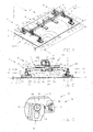
figure 1 represents a magnetic gripper according to the invention, used for lifting a steel plate, seen in perspective; -
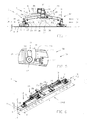
figure 2 represents a side elevation according to arrow F2 of the magnetic gripper fromfigure 1 , in a condition in which the magnetic gripper rests with its weight on the steel plate; -
figure 3 shows the part of the magnetic gripper indicated by F3 infigure 2 to a larger scale; -
figure 4 , analogous tofigure 2 , represents a side elevation of the magnetic gripper fromfigure 1 , in a condition in which the weight of the magnetic gripper does not rest on the steel plate yet; -
figure 5 shows the part of the magnetic gripper indicated by F5 infigure 4 to a larger scale; -
figure 6 shows the magnetic gripper fromfigures 1 and 2 , used for lifting a steel profile, whereby pairs of bistable magnets of the magnetic gripper are switched in another position; -
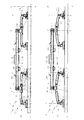
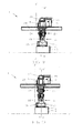
figures 7 and 8 show front views of the magnetic gripper fromfigure 6 according to arrow F7/F8, in a condition in which the magnetic gripper either or not rests with its weight on the steel profile; and, -
figures 9 and 10 show lateral views according to arrow F9/F10 in the conditions according tofigures 7 and 8 respectively. - The
magnetic gripper 1 according to the invention as represented in the figures is designed for grabbing and releasingmagnetic materials 2. -
Figures 1, 2 and4 represent asteel plate 3 as an example of amagnetic material 2 to be taken hold of, typically with rather large dimensions in two directions XX' and YY', according to the width B and the length L of thesteel plate 3 respectively, and with a small dimension in the remaining direction ZZ' according to the thickness D of thesteel plate 3. -
Figures 6 to 10 illustrate a situation whereby themagnetic gripper 1 is used to take hold of amagnetic material 2 in the shape of a steel profile 4, typically with a rather large dimension in only one direction XX' according to the length L of the steel profile 4 and with rather small dimensions in the other directions YY' and ZZ' compared to the latter, according to the height H and the width B of the steel profile 4. - Naturally, other objects made of
magnetic materials 2 are not excluded, such as steel profiles, structural steel bars or steel plates having other shapes, bulk materials or waste scrap and so on. - The
magnetic gripper 1 is provided with aframe 5 forming askeleton 5 in the given example, whereby thisskeleton 5 in this case contains acentral beam 6 consisting of a hollowmetal box profile 6 extending in a direction UU' here. - At both free ends 7 and 8 of the central beam is in each case mounted a
suspension 9. - The
frame 5 may for example be made of carbon steel, or possibly of aluminium so as to reduce the weight. - In the given example, the
suspensions 9 form a sort ofcrosspieces 9 which generally extend in a direction VV' on either side of thecentral beam 6 and which are provided with aconnection 10 in the middle with which they are connected to thecentral beam 6. - Every
suspension 9 further has a pair offree ends bistable magnets 13. - Every
suspension 9 is in this case bolted to thecentral beam 6 by means of bolts and nuts, such that thesuspensions 9 can be easily repositioned on thecentral beam 6, for example so as to be able to adjust themagnetic gripper 1 as a function of the shape of themagnetic material 2 to be grabbed. - In the embodiment as discussed here, the
connection 10 between asuspension 9 and thecentral beam 6 is made rotatable, whereby thesuspensions 9 can be rotated round a shaft WW' which is perpendicular to the direction UU' on the one hand, i.e. the direction in which thecentral axis 6 extends, and to the direction VV' on the other hand, i.e. the direction in which thesuspension 9 concerned extends. - According to a preferred embodiment of the invention, a
suspension 9 can rotate by means of therotatable connection 10 thanks to the manual intervention of an operator. - The operator may hereby for example unlock a mechanical lock, after which a rotation of the
suspension 9 into the desired position is possible. - Thereafter, the
connection 10 can be re-fixed by the operator by locking the mechanical lock again. - Such a mechanical lock may for example consist of a pin which can be moved to and fro, provided on a first part of the
connection 10, and of holes which are uniformly distributed over the circumference of a second part of theconnection 10 whereby, by introducing the pin in one of the holes, theconnection 10 can be fixed in the desired position. - Such a pin is preferably spring-loaded, such that it can be automatically maintained in the hole concerned as long as it is not unlocked by an operator.
- Thus, the direction VV' of every
suspension 9 in relation to thecentral axis 6 can be changed by a rotation about the axis WW', whereby in the case offigure 1 , thesuspensions 9 which are designed as a kind ofcrosspieces 9 effectively stand transversely to thecentral axis 6, such that the directions VV' are perpendicular to the direction UU', whereas in the case offigure 6 , thesuspensions 9 are provided parallel to thecentral axis 6, such that the directions VV' extend parallel to the direction UU'. - As the
suspensions 9 can be positioned in relation to thecentral beam 6, a greater degree of freedom is obtained for positioning thebistable magnets 13. - According to the invention however, a simpler version of a
magnetic gripper 1 is not excluded, whereby theframe 5 merely consists of parts that are fixedly connected to one another and whereby thebistable magnets 13 are solely positioned in relation to amagnetic material 2 by positioning theframe 5 itself. - The
bistable magnets 13 are magnets which, as the name suggests, have two stable positions, whereby such abistable magnet 13 can be switched in particular between an on and off mode. - In on mode, the
bistable magnet 13 concerned can exert a magnetic gripping on amagnetic material 2 to be taken hold of, whereas in off mode, thebistable magnet 13 concerned can exert no or practically no magnetic gripping force on amagnetic material 2 to be taken hold of. - As explained in the introduction, both modes are stable since the magnetic field which is switched on to grab a
magnetic material 2 or which is switched off to release themagnetic material 2 again is only provided by permanent magnets, either or not combined with remnant magnetism generated in a core, and thus is not provided by an electromagnet whose magnetic field can be interrupted by a power failure. - Every pair of
bistable magnets 13 is in this case integrated in afoot 14 provided with anupright piece 15 which extends in a direction TT' parallel to the direction WW' around which itssuspension 9 can rotate. - At one
far end 16, theupright piece 15 is fixedly connected to a flat sole 17, designed to make contact with themagnetic material 2 to be picked up. - The
flat soles 17 are in this case rectangular, whereby twobistable magnets 13 at a time are integrated in a sole 17 and whereby thebistable magnets 13 of such a pair are placed next to one another in the direction VV' of thesuspension 9 onto which they are connected. - The
upright piece 15 is provided in the middle of the flat sole 17 and is perpendicular to the latter. - The other
far end 18 of theupright piece 15 of thefoot 14 is suspended to thefree end suspension 9 by means of acardan connection 19, such that the direction TT' of theupright piece 15 is aligned in the direction of gravity as far as thefeet 14 are freely suspended to theirsuspension 9. - To this end, the
cardan connection 19 contains anintermediate piece 20 which is hinge-mounted to thefar end 18 of theupright piece 15 by means of ahinge 21 on the one hand, which hinge 21 makes it possible for thefoot 14 to rotate about anaxis 22 which extends parallel to the direction VV' of thesuspension 9 concerned. - On the other hand, the
intermediate piece 20 is hinge-mounted to the freefar end suspension 9 concerned by means of ahinge 23, which hinge 23 allows for a rotation about anaxis 24 perpendicular to theother axis 22 and which extends perpendicular to the direction VV' of thesuspension 9 concerned. - In the given embodiment, the
suspensions 9 and thefeet 14 with the pairs ofbistable magnets 13 hang from thecentral beam 6 or they support thecentral beam 6 in such a manner that theframe 5 as a whole can be easily placed on themagnetic material 2 to be taken hold of, whereby in particular when picking up asteel plate 3, all thefeet 14 are aligned in a plane containing the directions XX' and YY', and when grabbing a rather one-dimensional structure such as a steel profile 4, thefeet 14 are aligned according to a line XX'. - Obviously, totally different forms suitable for grasping other sorts of materials are not excluded according to the invention.
- In the given example, the
magnetic gripper 1 also contains only twosuspensions 9 with in each case a pair ofbistable magnets 13 on each of the far ends 11 and 12 thereof, whereby themagnets 13 are provided in pairs and according to a symmetrical pattern to theframe 5, which can be easily expanded according to the invention to several pairs ofbistable magnets 13 or even to totally different configurations should this be required for a certain application. - The
magnetic gripper 1 is further provided with acontrol unit 25 with which thebistable magnets 13 can be controlled or switched into the corresponding desired positions, for example by means of electrical pulses generated by thecontrol unit 25. - An
electric battery 26 serves as an autonomous source of energy for generating the electrical pulses. - Since the
bistable magnets 13 only consume energy when being switched from one mode to another, such abattery 26 may last very long without having to be reloaded, whereby several tens or even thousands of switch-overs of thebistable magnets 13 are possible. - According to a possible embodiment of a
magnetic gripper 1 according to the invention, thecontrol unit 25 is also designed for rotating each and everysuspension 9 in relation to thecentral beam 6 so as to place thebistable magnets 13 in a position which is appropriate for picking up themagnetic material 2 concerned. - In this way, it is possible to avoid the manual intervention of an operator for this purpose.
- More generally, a
magnetic gripper 1 according to the invention may contain one or severalbistable magnets 13 provided on a moving part of theframe 5 which may have another shape than thesuspensions 9 from the figures, such as for example on a movable arm or the like. - Such a movable part can be moved and positioned in relation to the remaining part of the
frame 5 by controlling it via thecontrol unit 25. - As a result, as in the embodiment shown, it may be possible to better position the
bistable magnets 13 as a function of the shape of themagnetic material 2 to be picked up, before themagnetic material 2 is being grabbed, by placing themagnetic gripper 1 on it with a lifting device. - In other embodiments it is also possible to control the movement of the movable part in such a manner by means of the
control unit 25 that one or severalbistable magnets 13 are brought directly in contact with themagnetic material 2 to be picked up by said movement. - In order to make it possible to easily lift the
magnetic gripper 1 with a lifting device, gripping means 27 are provided according to the invention. - These gripping means 27 in this case contain a pair of box-shaped
beams 28 with open far ends provided centrally on theframe 5 on the one hand, in particular on thecentral beam 6, and which extend at right angles to saidcentral beam 6. - Said box-shaped
beams 28 are designed to grasp and lift the magnetic gripper with a forklift, by sliding its forks via the open far ends in the box-shapedbeams 28. - On the other hand, the gripping means 27 in this case also comprise a pair of
eyes 29 provided at an equal distance from the middle of thecentral beam 6, which may be used to lift or grasp themagnetic gripper 1 with a pair of hooks of a hoist or crane or the like. - According to a preferred embodiment, a
magnetic gripper 1 according to the invention is provided with detection means 30 making it possible to detect either a complete grab-ready or incomplete grab-ready running order. - A complete grab-ready running order refers to a state of the
magnetic gripper 1 in which allbistable magnets 13 of themagnetic gripper 1 are grab-ready,bistable magnets 13, as they can each reach a grabbing state for picking upmagnetic material 2 and can hereby each make a contribution to achieving the necessary magnetic lifting force for lifting themagnetic material 2. - Of course, a minimum requirement for reaching a complete grab-ready running order is that each
bistable magnet 13 can be put into contact with themagnetic material 2 to be grabbed. - An incomplete grab-ready running order on the other hand refers to a condition of the
magnetic gripper 1 whereby one or severalbistable magnets 13 of themagnetic gripper 1 arebistable magnets 13 that are not grab-ready, as they cannot reach a grabbing state since the magnets concerned are not capable to get hold of themagnetic material 2 concerned, for example as they cannot make contact with themagnetic material 2 or as there is nomagnetic material 2 available at the contact point of the piece to be grabbed or the like. - In the embodiment of a
magnetic gripper 1 according to the invention as illustrated in the figures, said detection means 30 are provided as well, which are shown in greater detail infigures 3 and5 . - These detection means 30 in this case consist of detection switches 31 which are switched during the transition from a nongrab-ready running order, whereby the
magnetic gripper 1 is being lifted at thebistable magnet 13 ormagnets 13 concerned by a lifting device, to a grab-ready running order, whereby themagnetic gripper 1 is not being lifted at the bistable magnet by a lifting device, and vice versa. - To this end, the
suspensions 9 in the given example are made in two pieces, like a pair of scissors with twolegs 32 that are hinge-mounted to one another in the centre of thesuspension 9 by means of ahinge 33 whose axis ofrotation 34 extends in the direction UU' of thecentral axis 6. - Each
leg 32 of asuspension 9 hereby has along leg part 35 with a long lever arm with respect to thehinge 33 and which extends up to the corresponding freefar end foot 14 andbistable magnet 13 concerned, as well as ashort leg part 36 with a short lever arm with respect to thehinge 33 and which extends in the direction of thefoot 14 with thebistable magnet 13 of theother leg 32. - Each
suspension 9 is hereby provided with a pair of detection switches 31 which are in this case provided between along leg part 35 and ashort leg part 36 of thesuspension 9 on either side of thecentral beam 6. - To this end, the detection switches 31 have a
housing 37 on thelong leg part 35 concerned of one of thelegs 32, whereby aswitching section 38, extending as of saidhousing 37, is equipped with apin 39 placed in aslot 40 which is provided in everyshort leg part 35 of theother leg 32 to this end. - When the
magnetic gripper 1 rests with is weight on themagnetic material 2 to be picked up, as is the case infigures 2 ,7 and9 , thelegs 32 of eachsuspension 9 will hinge somewhat apart aroundhinge 33, as a result of which thepin 39 of adetection switch 31 will position itself at onefar end 41 of theslot 40 concerned, as is represented in greater detail infigure 3 . - However, when the
magnetic gripper 1 is lifted by a lifting device, and thus the weight of themagnetic gripper 1 no longer rests on magnetic material to be picked up, which situation is illustrated infigures 4 ,8 and10 , then thelegs 32 of eachsuspension 9 will hinge somewhat towards one another around hinge 33, as a result of which thepin 39 of adetection switch 31 will position itself on the otherfar end 42 of theslot 40 concerned, which is represented in more detail infigure 5 . - Depending on the position of the
pin 39 in theslot 40, theappropriate detection switch 31 will be switched, as a result of which said switching in this case corresponds to observing a condition in which the weight of themagnetic gripper 1 either or not rests onmagnetic material 2 at thebistable magnet 13 concerned. - A complete grab-ready running order is in this case a condition whereby one of the detection switches 31 of each
bistable magnet 13 is switched into the condition as represented infigure 3 , whereby allfeet 14 rest on themagnetic material 2 and carry a part of the weight of themagnetic gripper 1. - Such detection means 30 are very useful, as they allow the
magnetic gripper 1 to perform in full-automatic mode, whereby this mode can preferably be set by an operator via thecontrol unit 25. - In full-automatic mode, when a complete grab-ready running order is detected by means of the detection means 30, the
control unit 25 can automatically switch allbistable magnets 13 into on mode by means of corresponding electrical pulses generated by thecontrol unit 25, such that they can exert a magnetic force on themagnetic material 2. - To ensure a safe operation, the
control unit 25 according to the invention is provided with a security which, when an incomplete grab-ready running order is detected by the detection means 30, prevent anymagnetic material 2 being lifted by switching allbistable magnets 13 into off mode. - Optionally, there can be ensured that, as an alternative, the
control unit 25 is provided with a security which, when an incomplete grab-ready running order is detected by the detection means 30, nevertheless allows for the magnetic material to be lifted by switching all the grab-ready,bistable magnets 13 into on mode and by additionally magnetizing them with an electrical pulse so as to increase the magnetic gripping force of the switched-onbistable magnets 13 to the extent that the lack of any gripping force at the nongrab-ready,bistable magnets 13 is compensated. - In this manner, different materials having very different shapes and weights can be taken hold of and moved in a very efficient and automatic manner.
- A
magnetic gripper 1 according to the invention is preferably also equipped with signalling means, for example in the shape of one or several LEDs or an LCD screen or the like, so as to be able to signal certain conditions of themagnetic gripper 1 to an operator. - Typically, such signalling means can for example be used to inform an operator that the
magnetic gripper 1 is in full grab-ready running order. - According to a preferred embodiment of a
magnetic gripper 1 according to the invention, thebistable magnets 13 are additionally provided with an adjustable electromagnet for generating a demagnetizing field which is adjustable by thecontrol unit 25, when thebistable magnet 13 concerned is switched in on mode, so as to set the magnitude of the total available magnetic gripping force in on mode. - Thanks to an appropriate choice of the magnitude of the demagnetizing field, it can for example be made sure with such an embodiment that the
magnetic gripper 1 picks up only a single steel plate at a time from a stack of steel plates when thebistable magnets 13 are switched on to that end. - The
control unit 25 is preferably also adjustable in a mode of operation by an operator by means of a remote control, whereby the operator can put thebistable magnets 13 in a switched-on or switched-off mode by means of a remote control. - Such an operation mode can be particularly useful when for example scrap waste needs to be dumped with the
magnetic gripper 1, whereby it may be sufficient for an operator to observe from a distance that the liftedmagnetic materials 2 are in a position in which it is safe to switch thebistable magnets 13 into off mode in order to dump the waste there. - According to yet another preferred embodiment, the
control unit 25 can also be set in a manual mode of operation by an operator, whereby the operator can manually put thebistable magnets 13 jointly or separately in a switched-on or switched-off mode. - This mode of operation is meant rather for emergencies or instances where something has gone wrong.
- Obviously, many other possible embodiments of a
magnetic gripper 1 according to the invention are not excluded either. - The
magnetic gripper 1 may for example be adapted to pick up and lift rather light objects or much heavier objects, for example objects having a weight which may range for example from 28 kg to 28 Mt. - To this end, the number of bistable magnets with which the
magnetic gripper 1 is equipped can be increased or decreased accordingly. - Also, many different embodiments of a
magnetic gripper 1 according to the invention are possible, adapted as a function of the dimensions of the objects to be picked up, whereby theframe 3 can be enlarged or reduced accordingly, carried out with more or less beams, carried out as a box or plate-shaped element, provided with fold-out or pull-out sections and so on. - The dimensions of the objects made of magnetic material may strongly vary. For example, the
magnetic gripper 1 may be designed for standard steel plates of 1 m by 2 m and 0.5 mm thick, but the magnetic gripper may just as well be designed for gripping steel plates having dimensions up to 12 m by 3 m and with strongly varying thicknesses and so on. - In other possible embodiments, a
magnetic gripper 1 may be integrated in a system with a robot or laser cutter. - The
control unit 25 of themagnetic gripper 1 may hereby be part of the robot or the laser cutter, such that it can monitor and control themagnetic gripper 1, whereby themagnetic gripper 1, and in particular itsbistable magnets 13, can be controlled differently, for example as a function of the size or shape of thematerial 2 to be grabbed, all of this fully automatically, without any operator intervention. - The invention is by no means restricted to the embodiments of a
magnetic gripper 1 according to the invention described by way of example and represented in the accompanying drawings; on the contrary, such amagnetic gripper 1 can be made in many different ways while still remaining within the scope of the claims.
Claims (15)
- Magnetic gripper (1) for grabbing and releasing magnetic materials (2), comprising a frame (5) provided with gripping means (27) with which the magnetic gripper (1) can be grabbed by a lifting device, characterized in that the magnetic gripper (1) further contains at least the following elements:- two or more bistable magnets (13), which can at least be switched between an on mode, in which the bistable magnet (13) concerned can exert a magnetic gripping force on magnetic material (2) to be grabbed, and an off mode, in which the bistable magnet (13) concerned can exert no or practically no magnetic gripping force on magnetic material (2) to be grabbed;- a control unit (25) for generating electrical pulses to put the bistable magnets (13) in the corresponding desired positions; and,- an electric battery (26) which serves as an autonomous source of energy for generating the electrical pulses.
- Magnetic gripper (1) according to claim 1, characterized in that the magnetic gripper (1) contains several bistable magnets (13) provided in pairs and according to a symmetrical pattern to the frame (5).
- Magnetic gripper (1) according to claim 1 or 2, characterized in that the frame (5) comprises a central beam (6) and in that at least one suspension (9) is provided on the central beam extending in a direction (VV') on either side thereof, connected with its centre to the central beam (6) and having a pair of free ends (11,12) onto which is provided one pair of bistable magnets (13) at a time.
- Magnetic gripper (1) according to one or several of the preceding claims, characterized in that one or several bistable magnets (13) are provided on a moving part of the frame (5), which can be moved with respect to the remaining part of the frame (5) via the control unit (25).
- Magnetic gripper (1) according to claims 3 and 4, characterized in that an aforesaid suspension (9) forms such a moving part of the frame, whereby the movement consists of a rotation of the suspension (9) around an axis extending in a direction (WW') which is perpendicular to the central beam (6), as well as to the direction (VV') in which the suspension (9) concerned extends.
- Magnetic gripper (1) according to one or several of the preceding claims, characterized in that one or several bistable magnets (13) are provided with an adjustable electromagnet for generating a demagnetizing field which can be adjusted by the control unit (25), when the bistable magnet (13) is switched in on mode, so as to set the magnitude of the total available magnetic gripping force in said on mode.
- Magnetic gripper (1) according to one or several of the preceding claims, characterized in that the magnetic gripper (1) is provided with detection means (30) making it possible to detect either a complete grab-ready running order, or an incomplete grab-ready running order, whereby in the complete grab-ready running order all bistable magnets (13) are grab-ready, bistable magnets (13), as they can get in a grabbing condition in which the bistable magnets (13) concerned are capable of getting hold of the magnetic material (2) concerned, whereas in the incomplete grab-ready running order, one or several of the bistable magnets (13) are nongrab-ready, bistable magnets (13), as they cannot get in a grabbing condition since the bistable magnets (13) concerned are not capable of getting hold of the magnetic material (2) concerned.
- Magnetic gripper (1) according to claim 7, characterized in that the detection means (30) consist of detection switches (31) which are switched during the transition from a nongrab-ready running order, in which the magnetic gripper (1) is being lifted at the bistable magnet (13) concerned by a lifting device, to a grab-ready running order, in which the magnetic gripper (1) is not being lifted at the bistable magnet (13) concerned by a lifting device, and vice versa.
- Magnetic gripper (1) according to claims 7 or 8, characterized in that the control unit (25) is provided with a security which, when an incomplete grab-ready running order is detected by the detection means (30), prevent any magnetic material (2) being lifted by switching all bistable magnets (13) into off mode.
- Magnetic gripper (1) according to claims 8 and 9, characterized in that the control unit (25) can be set in a full-automatic mode of operation by an operator, whereby in this mode of operation, when a complete grab-ready running order is detected by the control unit (25), all bistable magnets (13) are automatically switched into on mode by means of corresponding electrical pulses generated by the control unit (25).
- Magnetic gripper (1) according to claims 7 or 8, characterized in that the control unit (25) is provided with a security which, when an incomplete grab-ready running order is detected by the detection means (30), allow any magnetic material (2) to be lifted by switching all grab-ready, bistable magnets (13) into on mode and by additionally magnetizing them with an electrical pulse so as to increase the magnetic gripping force of the switched-on bistable magnets (13) to the extent that the lack of any gripping force at the nongrab-ready, bistable magnets (13) is compensated.
- Magnetic gripper (1) according to one or several of the preceding claims, characterized in that the control unit (25) can be set in a mode of operation by an operator by means of a remote control, whereby the operator can put the bistable magnets (13) in either on mode or off mode by means of a remote control.
- Magnetic gripper (1) according to one or several of the preceding claims, characterized in that the control unit (25) can be set in manual mode by an operator, whereby the operator can manually put the bistable magnets (13) jointly and/or separately in either on mode or off mode.
- Magnetic gripper (1) according to one or several of the preceding claims, characterized in that the battery (26) allows for more than a thousand switches of the bistable magnets (13) between an on and off mode without being reloaded.
- Magnetic gripper (1) according to one or several of the preceding claims, characterized in that the gripping means comprise a pair of box-shaped beams (28) provided centrally on the frame so as to be able to grab the magnetic gripper (1) with a forklift.
Priority Applications (1)
| Application Number | Priority Date | Filing Date | Title |
|---|---|---|---|
| PL14165435T PL2796400T3 (en) | 2013-04-24 | 2014-04-22 | Magnetic gripper for grabbing and releasing magnetic materials. |
Applications Claiming Priority (1)
| Application Number | Priority Date | Filing Date | Title |
|---|---|---|---|
| BE2013/0289A BE1021277B1 (en) | 2013-04-24 | 2013-04-24 | MAGNETIC HOOK FOR DETERMINING AND RELEASING MAGNETIC MATERIALS |
Publications (2)
| Publication Number | Publication Date |
|---|---|
| EP2796400A1 EP2796400A1 (en) | 2014-10-29 |
| EP2796400B1 true EP2796400B1 (en) | 2015-12-30 |
Family
ID=48699466
Family Applications (1)
| Application Number | Title | Priority Date | Filing Date |
|---|---|---|---|
| EP14165435.0A Not-in-force EP2796400B1 (en) | 2013-04-24 | 2014-04-22 | Magnetic gripper for grabbing and releasing magnetic materials. |
Country Status (3)
| Country | Link |
|---|---|
| EP (1) | EP2796400B1 (en) |
| BE (1) | BE1021277B1 (en) |
| PL (1) | PL2796400T3 (en) |
Cited By (1)
| Publication number | Priority date | Publication date | Assignee | Title |
|---|---|---|---|---|
| WO2021103244A1 (en) * | 2019-11-28 | 2021-06-03 | 璟泰(清远)橡胶工业有限公司 | Die-loading assembly by hoisting, and forklift |
Families Citing this family (6)
| Publication number | Priority date | Publication date | Assignee | Title |
|---|---|---|---|---|
| RU2582742C1 (en) * | 2015-03-16 | 2016-04-27 | Общество с ограниченной ответственностью "ЭРГА Плюс" | Electromagnets with electrical permanent magnetic grippers |
| CN106006481B (en) * | 2016-08-09 | 2019-06-14 | 营口市工业电磁盘厂 | Fork truck Special electromagnetic suspender |
| US11104552B2 (en) * | 2018-09-26 | 2021-08-31 | Cisco Technology, Inc. | Docking and undocking payloads from mobile robots |
| CN109968430B (en) * | 2019-02-15 | 2021-06-01 | 高宇泽 | Net cushion manufacturing assembly line and manufacturing method |
| CN112978554B (en) * | 2021-03-01 | 2022-04-08 | 中铁十九局集团轨道交通工程有限公司 | Steel pipe installation and lifting device of shield tunneling machine |
| CN116768011B (en) * | 2023-05-08 | 2024-04-16 | 中电建成都铁塔有限公司 | Single steel plate lifting device and application method thereof |
Family Cites Families (3)
| Publication number | Priority date | Publication date | Assignee | Title |
|---|---|---|---|---|
| JP2002302374A (en) * | 2001-03-29 | 2002-10-18 | Kurimoto Ltd | Material reversing device |
| DE202005016489U1 (en) * | 2005-10-20 | 2007-03-01 | Liebherr-Hydraulikbagger Gmbh | Hydraulic excavator with built-in magnetic crosshead |
| CA2739247A1 (en) * | 2008-10-17 | 2010-04-22 | Hh Intellitech Aps | Lifting vehicle |
-
2013
- 2013-04-24 BE BE2013/0289A patent/BE1021277B1/en not_active IP Right Cessation
-
2014
- 2014-04-22 PL PL14165435T patent/PL2796400T3/en unknown
- 2014-04-22 EP EP14165435.0A patent/EP2796400B1/en not_active Not-in-force
Cited By (1)
| Publication number | Priority date | Publication date | Assignee | Title |
|---|---|---|---|---|
| WO2021103244A1 (en) * | 2019-11-28 | 2021-06-03 | 璟泰(清远)橡胶工业有限公司 | Die-loading assembly by hoisting, and forklift |
Also Published As
| Publication number | Publication date |
|---|---|
| EP2796400A1 (en) | 2014-10-29 |
| PL2796400T3 (en) | 2016-06-30 |
| BE1021277B1 (en) | 2015-10-13 |
Similar Documents
| Publication | Publication Date | Title |
|---|---|---|
| EP2796400A1 (en) | Magnetic gripper for grabbing and releasing magnetic materials. | |
| CN107708886B (en) | Ferromagnetic plate spreading and gripping device | |
| US20130320686A1 (en) | Magnetic lifting device | |
| US20230090943A1 (en) | Magnetic coupling device with at least one of a sensor arrangement and a degauss capability | |
| US12023770B2 (en) | Magnetic coupling device with at least one of a sensor arrangement and a degauss capability | |
| US20150203340A1 (en) | Variable Strength Magnetic End Effector for Lift Systems | |
| JP2018510790A5 (en) | ||
| JP2016539062A (en) | Permanent magnetic device | |
| US4943099A (en) | Tongs-like cargo hook device with automatic loading and unloading capability | |
| US4530028A (en) | Electromagnet with expandible cores for exciting coils | |
| US20250065460A1 (en) | Magnetic coupling device with at least one of a sensor arrangement and a degauss capability | |
| JP2022066932A (en) | Receiving base | |
| CN102905845A (en) | Attaching device, attaching arrangement and method for attaching object to be worked to working base | |
| CN108466933B (en) | Lifting device control system utilizing electromagnetic chuck, control method and application | |
| CN203095379U (en) | Environmentally-friendly electro-permanent magnetic lifting electromagnet | |
| RU2582742C1 (en) | Electromagnets with electrical permanent magnetic grippers | |
| GB2043354A (en) | Lifting device with permanent magnet heads | |
| EP2454743B1 (en) | Electromagnet for moving tubular members | |
| RU202746U1 (en) | Magnetic traverse for moving metal loads | |
| CN218341787U (en) | Small part plate polishing and fixing tool | |
| US6019406A (en) | Lifting-machine power gripper and components | |
| Sutera et al. | A novel design of a lightweight magnetic plate for a delivery drone | |
| US7791856B2 (en) | Method and apparatus for moving material | |
| CN106289763B (en) | A kind of automatic unlocking mechanism for universal self shifter experimental rig | |
| CN112479001B (en) | Automatic hoisting equipment, hoisting method and hoisting method |
Legal Events
| Date | Code | Title | Description |
|---|---|---|---|
| PUAI | Public reference made under article 153(3) epc to a published international application that has entered the european phase |
Free format text: ORIGINAL CODE: 0009012 |
|
| 17P | Request for examination filed |
Effective date: 20140422 |
|
| AK | Designated contracting states |
Kind code of ref document: A1 Designated state(s): AL AT BE BG CH CY CZ DE DK EE ES FI FR GB GR HR HU IE IS IT LI LT LU LV MC MK MT NL NO PL PT RO RS SE SI SK SM TR |
|
| AX | Request for extension of the european patent |
Extension state: BA ME |
|
| R17P | Request for examination filed (corrected) |
Effective date: 20150429 |
|
| RBV | Designated contracting states (corrected) |
Designated state(s): AL AT BE BG CH CY CZ DE DK EE ES FI FR GB GR HR HU IE IS IT LI LT LU LV MC MK MT NL NO PL PT RO RS SE SI SK SM TR |
|
| RIC1 | Information provided on ipc code assigned before grant |
Ipc: B66F 9/18 20060101ALI20150513BHEP Ipc: B66C 1/06 20060101AFI20150513BHEP |
|
| GRAP | Despatch of communication of intention to grant a patent |
Free format text: ORIGINAL CODE: EPIDOSNIGR1 |
|
| INTG | Intention to grant announced |
Effective date: 20150622 |
|
| GRAS | Grant fee paid |
Free format text: ORIGINAL CODE: EPIDOSNIGR3 |
|
| GRAA | (expected) grant |
Free format text: ORIGINAL CODE: 0009210 |
|
| AK | Designated contracting states |
Kind code of ref document: B1 Designated state(s): AL AT BE BG CH CY CZ DE DK EE ES FI FR GB GR HR HU IE IS IT LI LT LU LV MC MK MT NL NO PL PT RO RS SE SI SK SM TR |
|
| REG | Reference to a national code |
Ref country code: GB Ref legal event code: FG4D |
|
| REG | Reference to a national code |
Ref country code: CH Ref legal event code: EP |
|
| REG | Reference to a national code |
Ref country code: AT Ref legal event code: REF Ref document number: 767374 Country of ref document: AT Kind code of ref document: T Effective date: 20160115 |
|
| REG | Reference to a national code |
Ref country code: IE Ref legal event code: FG4D |
|
| REG | Reference to a national code |
Ref country code: DE Ref legal event code: R096 Ref document number: 602014000641 Country of ref document: DE |
|
| REG | Reference to a national code |
Ref country code: NL Ref legal event code: FP |
|
| REG | Reference to a national code |
Ref country code: LT Ref legal event code: MG4D |
|
| PG25 | Lapsed in a contracting state [announced via postgrant information from national office to epo] |
Ref country code: LT Free format text: LAPSE BECAUSE OF FAILURE TO SUBMIT A TRANSLATION OF THE DESCRIPTION OR TO PAY THE FEE WITHIN THE PRESCRIBED TIME-LIMIT Effective date: 20151230 Ref country code: HR Free format text: LAPSE BECAUSE OF FAILURE TO SUBMIT A TRANSLATION OF THE DESCRIPTION OR TO PAY THE FEE WITHIN THE PRESCRIBED TIME-LIMIT Effective date: 20151230 Ref country code: NO Free format text: LAPSE BECAUSE OF FAILURE TO SUBMIT A TRANSLATION OF THE DESCRIPTION OR TO PAY THE FEE WITHIN THE PRESCRIBED TIME-LIMIT Effective date: 20160330 |
|
| REG | Reference to a national code |
Ref country code: AT Ref legal event code: MK05 Ref document number: 767374 Country of ref document: AT Kind code of ref document: T Effective date: 20151230 |
|
| PG25 | Lapsed in a contracting state [announced via postgrant information from national office to epo] |
Ref country code: LV Free format text: LAPSE BECAUSE OF FAILURE TO SUBMIT A TRANSLATION OF THE DESCRIPTION OR TO PAY THE FEE WITHIN THE PRESCRIBED TIME-LIMIT Effective date: 20151230 Ref country code: RS Free format text: LAPSE BECAUSE OF FAILURE TO SUBMIT A TRANSLATION OF THE DESCRIPTION OR TO PAY THE FEE WITHIN THE PRESCRIBED TIME-LIMIT Effective date: 20151230 Ref country code: SE Free format text: LAPSE BECAUSE OF FAILURE TO SUBMIT A TRANSLATION OF THE DESCRIPTION OR TO PAY THE FEE WITHIN THE PRESCRIBED TIME-LIMIT Effective date: 20151230 Ref country code: GR Free format text: LAPSE BECAUSE OF FAILURE TO SUBMIT A TRANSLATION OF THE DESCRIPTION OR TO PAY THE FEE WITHIN THE PRESCRIBED TIME-LIMIT Effective date: 20160331 Ref country code: FI Free format text: LAPSE BECAUSE OF FAILURE TO SUBMIT A TRANSLATION OF THE DESCRIPTION OR TO PAY THE FEE WITHIN THE PRESCRIBED TIME-LIMIT Effective date: 20151230 |
|
| PG25 | Lapsed in a contracting state [announced via postgrant information from national office to epo] |
Ref country code: ES Free format text: LAPSE BECAUSE OF FAILURE TO SUBMIT A TRANSLATION OF THE DESCRIPTION OR TO PAY THE FEE WITHIN THE PRESCRIBED TIME-LIMIT Effective date: 20151230 Ref country code: CZ Free format text: LAPSE BECAUSE OF FAILURE TO SUBMIT A TRANSLATION OF THE DESCRIPTION OR TO PAY THE FEE WITHIN THE PRESCRIBED TIME-LIMIT Effective date: 20151230 |
|
| PG25 | Lapsed in a contracting state [announced via postgrant information from national office to epo] |
Ref country code: BE Free format text: LAPSE BECAUSE OF NON-PAYMENT OF DUE FEES Effective date: 20160430 Ref country code: SM Free format text: LAPSE BECAUSE OF FAILURE TO SUBMIT A TRANSLATION OF THE DESCRIPTION OR TO PAY THE FEE WITHIN THE PRESCRIBED TIME-LIMIT Effective date: 20151230 Ref country code: EE Free format text: LAPSE BECAUSE OF FAILURE TO SUBMIT A TRANSLATION OF THE DESCRIPTION OR TO PAY THE FEE WITHIN THE PRESCRIBED TIME-LIMIT Effective date: 20151230 Ref country code: IS Free format text: LAPSE BECAUSE OF FAILURE TO SUBMIT A TRANSLATION OF THE DESCRIPTION OR TO PAY THE FEE WITHIN THE PRESCRIBED TIME-LIMIT Effective date: 20160430 Ref country code: SK Free format text: LAPSE BECAUSE OF FAILURE TO SUBMIT A TRANSLATION OF THE DESCRIPTION OR TO PAY THE FEE WITHIN THE PRESCRIBED TIME-LIMIT Effective date: 20151230 Ref country code: AT Free format text: LAPSE BECAUSE OF FAILURE TO SUBMIT A TRANSLATION OF THE DESCRIPTION OR TO PAY THE FEE WITHIN THE PRESCRIBED TIME-LIMIT Effective date: 20151230 Ref country code: PT Free format text: LAPSE BECAUSE OF FAILURE TO SUBMIT A TRANSLATION OF THE DESCRIPTION OR TO PAY THE FEE WITHIN THE PRESCRIBED TIME-LIMIT Effective date: 20160502 Ref country code: RO Free format text: LAPSE BECAUSE OF FAILURE TO SUBMIT A TRANSLATION OF THE DESCRIPTION OR TO PAY THE FEE WITHIN THE PRESCRIBED TIME-LIMIT Effective date: 20151230 |
|
| REG | Reference to a national code |
Ref country code: DE Ref legal event code: R097 Ref document number: 602014000641 Country of ref document: DE |
|
| PG25 | Lapsed in a contracting state [announced via postgrant information from national office to epo] |
Ref country code: DK Free format text: LAPSE BECAUSE OF FAILURE TO SUBMIT A TRANSLATION OF THE DESCRIPTION OR TO PAY THE FEE WITHIN THE PRESCRIBED TIME-LIMIT Effective date: 20151230 |
|
| PLBE | No opposition filed within time limit |
Free format text: ORIGINAL CODE: 0009261 |
|
| STAA | Information on the status of an ep patent application or granted ep patent |
Free format text: STATUS: NO OPPOSITION FILED WITHIN TIME LIMIT |
|
| 26N | No opposition filed |
Effective date: 20161003 |
|
| PG25 | Lapsed in a contracting state [announced via postgrant information from national office to epo] |
Ref country code: LU Free format text: LAPSE BECAUSE OF FAILURE TO SUBMIT A TRANSLATION OF THE DESCRIPTION OR TO PAY THE FEE WITHIN THE PRESCRIBED TIME-LIMIT Effective date: 20160422 Ref country code: BE Free format text: LAPSE BECAUSE OF FAILURE TO SUBMIT A TRANSLATION OF THE DESCRIPTION OR TO PAY THE FEE WITHIN THE PRESCRIBED TIME-LIMIT Effective date: 20151230 |
|
| REG | Reference to a national code |
Ref country code: IE Ref legal event code: MM4A |
|
| REG | Reference to a national code |
Ref country code: FR Ref legal event code: ST Effective date: 20161230 |
|
| PG25 | Lapsed in a contracting state [announced via postgrant information from national office to epo] |
Ref country code: FR Free format text: LAPSE BECAUSE OF NON-PAYMENT OF DUE FEES Effective date: 20160502 |
|
| PG25 | Lapsed in a contracting state [announced via postgrant information from national office to epo] |
Ref country code: SI Free format text: LAPSE BECAUSE OF FAILURE TO SUBMIT A TRANSLATION OF THE DESCRIPTION OR TO PAY THE FEE WITHIN THE PRESCRIBED TIME-LIMIT Effective date: 20151230 |
|
| PG25 | Lapsed in a contracting state [announced via postgrant information from national office to epo] |
Ref country code: IE Free format text: LAPSE BECAUSE OF NON-PAYMENT OF DUE FEES Effective date: 20160422 |
|
| REG | Reference to a national code |
Ref country code: CH Ref legal event code: PL |
|
| PG25 | Lapsed in a contracting state [announced via postgrant information from national office to epo] |
Ref country code: LI Free format text: LAPSE BECAUSE OF NON-PAYMENT OF DUE FEES Effective date: 20170430 Ref country code: CH Free format text: LAPSE BECAUSE OF NON-PAYMENT OF DUE FEES Effective date: 20170430 |
|
| PG25 | Lapsed in a contracting state [announced via postgrant information from national office to epo] |
Ref country code: HU Free format text: LAPSE BECAUSE OF FAILURE TO SUBMIT A TRANSLATION OF THE DESCRIPTION OR TO PAY THE FEE WITHIN THE PRESCRIBED TIME-LIMIT; INVALID AB INITIO Effective date: 20140422 |
|
| PG25 | Lapsed in a contracting state [announced via postgrant information from national office to epo] |
Ref country code: MT Free format text: LAPSE BECAUSE OF NON-PAYMENT OF DUE FEES Effective date: 20160430 Ref country code: MC Free format text: LAPSE BECAUSE OF FAILURE TO SUBMIT A TRANSLATION OF THE DESCRIPTION OR TO PAY THE FEE WITHIN THE PRESCRIBED TIME-LIMIT Effective date: 20151230 Ref country code: MK Free format text: LAPSE BECAUSE OF FAILURE TO SUBMIT A TRANSLATION OF THE DESCRIPTION OR TO PAY THE FEE WITHIN THE PRESCRIBED TIME-LIMIT Effective date: 20151230 Ref country code: CY Free format text: LAPSE BECAUSE OF FAILURE TO SUBMIT A TRANSLATION OF THE DESCRIPTION OR TO PAY THE FEE WITHIN THE PRESCRIBED TIME-LIMIT Effective date: 20151230 |
|
| PGFP | Annual fee paid to national office [announced via postgrant information from national office to epo] |
Ref country code: NL Payment date: 20180413 Year of fee payment: 5 |
|
| PG25 | Lapsed in a contracting state [announced via postgrant information from national office to epo] |
Ref country code: BG Free format text: LAPSE BECAUSE OF FAILURE TO SUBMIT A TRANSLATION OF THE DESCRIPTION OR TO PAY THE FEE WITHIN THE PRESCRIBED TIME-LIMIT Effective date: 20151230 |
|
| PGFP | Annual fee paid to national office [announced via postgrant information from national office to epo] |
Ref country code: DE Payment date: 20180517 Year of fee payment: 5 |
|
| PGFP | Annual fee paid to national office [announced via postgrant information from national office to epo] |
Ref country code: IT Payment date: 20180426 Year of fee payment: 5 Ref country code: PL Payment date: 20180511 Year of fee payment: 5 |
|
| PG25 | Lapsed in a contracting state [announced via postgrant information from national office to epo] |
Ref country code: TR Free format text: LAPSE BECAUSE OF FAILURE TO SUBMIT A TRANSLATION OF THE DESCRIPTION OR TO PAY THE FEE WITHIN THE PRESCRIBED TIME-LIMIT Effective date: 20151230 Ref country code: AL Free format text: LAPSE BECAUSE OF FAILURE TO SUBMIT A TRANSLATION OF THE DESCRIPTION OR TO PAY THE FEE WITHIN THE PRESCRIBED TIME-LIMIT Effective date: 20151230 |
|
| GBPC | Gb: european patent ceased through non-payment of renewal fee |
Effective date: 20180422 |
|
| PG25 | Lapsed in a contracting state [announced via postgrant information from national office to epo] |
Ref country code: GB Free format text: LAPSE BECAUSE OF NON-PAYMENT OF DUE FEES Effective date: 20180422 |
|
| REG | Reference to a national code |
Ref country code: DE Ref legal event code: R119 Ref document number: 602014000641 Country of ref document: DE |
|
| REG | Reference to a national code |
Ref country code: NL Ref legal event code: MM Effective date: 20190501 |
|
| PG25 | Lapsed in a contracting state [announced via postgrant information from national office to epo] |
Ref country code: DE Free format text: LAPSE BECAUSE OF NON-PAYMENT OF DUE FEES Effective date: 20191101 Ref country code: NL Free format text: LAPSE BECAUSE OF NON-PAYMENT OF DUE FEES Effective date: 20190501 |
|
| PG25 | Lapsed in a contracting state [announced via postgrant information from national office to epo] |
Ref country code: IT Free format text: LAPSE BECAUSE OF NON-PAYMENT OF DUE FEES Effective date: 20190422 |
|
| PG25 | Lapsed in a contracting state [announced via postgrant information from national office to epo] |
Ref country code: PL Free format text: LAPSE BECAUSE OF NON-PAYMENT OF DUE FEES Effective date: 20190422 |