EP2796368B1 - Integration of rotary electrical actuator for swashplateless individual blade control - Google Patents
Integration of rotary electrical actuator for swashplateless individual blade control Download PDFInfo
- Publication number
- EP2796368B1 EP2796368B1 EP14165212.3A EP14165212A EP2796368B1 EP 2796368 B1 EP2796368 B1 EP 2796368B1 EP 14165212 A EP14165212 A EP 14165212A EP 2796368 B1 EP2796368 B1 EP 2796368B1
- Authority
- EP
- European Patent Office
- Prior art keywords
- blade
- rotor
- actuator
- ibcs
- coupled
- Prior art date
- Legal status (The legal status is an assumption and is not a legal conclusion. Google has not performed a legal analysis and makes no representation as to the accuracy of the status listed.)
- Not-in-force
Links
Images


Classifications
-
- B—PERFORMING OPERATIONS; TRANSPORTING
- B64—AIRCRAFT; AVIATION; COSMONAUTICS
- B64C—AEROPLANES; HELICOPTERS
- B64C27/00—Rotorcraft; Rotors peculiar thereto
- B64C27/54—Mechanisms for controlling blade adjustment or movement relative to rotor head, e.g. lag-lead movement
- B64C27/72—Means acting on blades
- B64C2027/7205—Means acting on blades on each blade individually, e.g. individual blade control [IBC]
- B64C2027/7211—Means acting on blades on each blade individually, e.g. individual blade control [IBC] without flaps
- B64C2027/7216—Means acting on blades on each blade individually, e.g. individual blade control [IBC] without flaps using one actuator per blade
-
- Y—GENERAL TAGGING OF NEW TECHNOLOGICAL DEVELOPMENTS; GENERAL TAGGING OF CROSS-SECTIONAL TECHNOLOGIES SPANNING OVER SEVERAL SECTIONS OF THE IPC; TECHNICAL SUBJECTS COVERED BY FORMER USPC CROSS-REFERENCE ART COLLECTIONS [XRACs] AND DIGESTS
- Y02—TECHNOLOGIES OR APPLICATIONS FOR MITIGATION OR ADAPTATION AGAINST CLIMATE CHANGE
- Y02T—CLIMATE CHANGE MITIGATION TECHNOLOGIES RELATED TO TRANSPORTATION
- Y02T50/00—Aeronautics or air transport
- Y02T50/30—Wing lift efficiency
Definitions
- Exemplary embodiments of the invention generally relate to rotary wing aircrafts, and more particularly, to a control system for pitching the blades of a rotor of a rotary wing aircraft.
- Control of a rotary wing aircraft is affected by varying the pitch of the rotor blades individually as the rotor rotates and by varying the pitch of all of the blades together. These are known respectively as cyclic and collective pitch control. Blade pitch control of a rotary wing aircraft main rotor is commonly achieved through a swashplate.
- the swashplate is typically concentrically mounted about the rotor shaft.
- the swashplate generally includes two rings connected by a series of bearings with one ring connected to the airframe (stationary swashplate) and the other ring connected to the rotor hub (rotating swashplate).
- the rotating ring is connected to the rotor hub through a pivoted link device typically referred to as "scissors", with the static ring similarly connected to the airframe.
- the rotating swashplate rotates relative the stationary swashplate. Apart from rotary motion, the stationary and rotating swashplate otherwise move as a unitary component. Cyclic control is achieved by tilting the swashplate relative to a rotor shaft and collective control is achieved by translating the swashplate along the rotor shaft.
- US 8 235 324 B1 discloses a rotor control system comprising electrical actuators and blade rotor roots wherein electrical actuators cannot be operated independently.
- US 8 197 205 B2 a rotor system with a plurality of actuators configured to move each rotor blade about a pitch axis independent of the other rotor blades.
- the Japanese document H0 911 994 A shows a fine control method for helicopters.
- the helicopter blades shown at WO 2005/100154 A1 can be set independently which is determined by a computer.
- EP 1 985 536 A2 shows the pitch setting by a centrally arranged frame and WO 2012/076705 A2 discloses a blade comprising an actuator is integrated within.
- Pitch control rods mounted between the main rotor blades and the rotating swashplate mechanically link the rotating swashplate to each individual main rotor blade.
- Main rotor servos extend between and attach to the stationary swashplate and the airframe. Displacement of the main rotor servos results in displacement of the stationary swashplate. Displacement of the stationary swashplate results in displacement of the rotating swashplate. Displacement of the rotating swashplate results in displacement of pitch control rods and therefore each individual main rotor blade.
- the swashplate and its associated linkages require a considerable amount of space, add to the aerodynamic drag of the aircraft, and account for a significant amount of gross weight. Due to their complexity and flight critical nature, the swashplate systems require regular and costly maintenance and inspection. Additionally, control inputs from swashplates are limited to collective and cyclic, which limit the resulting blade motion to steady and once per revolution rotation. Blade motions at higher harmonic frequencies have shown potential aircraft benefits such as improved performance and vibration. Thus, there is a continuing effort to improve blade pitch control for rotor systems of a rotary wing aircraft.
- an individual blade control system for a rotor system having a rotor hub
- IBCS individual blade control system
- Each blade cuff is configured to receive a rotor blade and rotate about a blade axis.
- a plurality of electrical actuators is mounted to the rotor hub adjacent at least one of the plurality of blade cuffs.
- Each electrical actuator is configured to rotate about an actuator axis.
- the plurality of blade axes and the plurality of actuator axes are arranged in a plane.
- Each electrical actuator is coupled to an adjacent blade cuff such that rotation of one of the plurality of electrical actuators causes a proportional rotation of one of the blade cuffs.
- Particular embodiments may include any of the following optional features, alone or in combination:
- the connector may be a push rod.
- a plurality of gears may extend between each of the plurality of electrical actuators and a coupled blade cuff.
- a first gear may be mounted to each of the plurality of electrical actuators and a second gear may be connected to each of the plurality of blade cuffs, and the first gear and the second gear of a coupled electrical actuator and blade cuff may be arranged in a meshing engagement.
- the first gear and the second gear may be substantially identical.
- the first gear and the second gear may be substantially different sizes to achieve a desired gear ratio.
- the actuator axis of each of the plurality of electrical actuators may be arranged parallel to the blade axis of the blade cuff coupled thereto.
- the actuator axis of each of the plurality of electrical actuators may be arranged at an angle to the blade axis of the blade cuff coupled thereto.
- Each of the plurality of electrical actuators may be positioned azimuthally between adjacent blade cuffs.
- Each of the plurality of electrical actuators may be coupled to an adjacent blade cuff with a plurality of connectors.
- a plurality of angled bevel gears may extend between each of the plurality of electrical actuators and a coupled blade cuff.
- a first gear may be mounted to each of the plurality of electrical actuators and a second gear may be connected to each of the plurality of blade cuffs, and the first gear and the second gear of a coupled electrical actuator and blade cuff may be arranged in a meshing engagement.
- the first gear and the second gear may be substantially identical.
- the first gear and the second gear may be substantially different sizes to achieve a desired gear ratio.
- a rotary wing aircraft including a rotor system having at least one rotatable rotor hub.
- a plurality of blade cuffs are mounted to the at least one rotor hub. Each blade cuff is configured to receive a rotor blade and rotate about a blade axis.
- a plurality of electrical actuators is mounted to the at least one rotor hub adjacent at least one of the plurality of blade cuffs. Each electrical actuator is configured to rotate about an actuator axis.
- the plurality of blade axes and the plurality of actuator axes are arranged in a plane. Each electrical actuator is coupled to an adjacent blade cuff such that rotation of one of the plurality of electrical actuators causes a similar rotation of one of the blade cuffs.
- Particular embodiments may include any of the following optional features, alone or in combination:
- a plurality of gears may extend between each of the plurality of electrical actuators and a coupled blade cuff.
- the actuator axis of each of the plurality of electrical actuators may be arranged at an angle to the blade axis of the blade cuff coupled thereto.
- Each of the plurality of electrical actuators may be positioned azimuthally between adjacent blade cuffs.
- Each of the plurality of electrical actuators may be coupled to an adjacent blade cuff with a plurality of connectors.
- the rotary wing aircraft further may comprise at least one pilot control operably coupled to a control system, wherein the control system is configured to command at least one of the electrical actuators to rotate upon receipt of a signal from the at least one pilot control.
- the control system may command the plurality of electrical actuators to rotate upon receipt of a signal from the at least one pilot control.
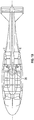
- FIGS. 1A and 1B illustrate an exemplary vertical takeoff and landing (VTOL) high speed compound or coaxial contra-rotating rigid rotor aircraft 10 having a dual, contra-rotating main rotor system 12, which rotates about a rotor axis of rotation R.
- the aircraft includes an airframe 14 which supports the dual, contra-rotating, coaxial main rotor system 12 as well as a translational thrust system 30 which provides translational thrust generally parallel to an aircraft longitudinal axis L.
- the main rotor system 12 includes a first rotor system 16 and a second rotor system 18. Each rotor system 16, 18 includes a plurality of rotor blades 20 mounted to a respective rotor hub 22, 24.
- the main rotor system 12 is driven by a main gearbox 26.
- the translational thrust system 30 may be any propeller system including, but not limited to a pusher propeller, a tractor propeller, a nacelle mounted propeller etc.
- the illustrated translational thrust system 30 includes a pusher propeller system 32 with a propeller rotational axis P oriented substantially horizontal and parallel to the aircraft longitudinal axis L to provide thrust for high speed flight.
- the translational thrust system 30 may be driven through the main gearbox 26 which also drives the rotor system 12.
- the main gearbox 26 is driven by one or more engines, illustrated schematically at E.
- the gearbox 26 may be interposed between one or more gas turbine engines E, the main rotor system 12 and the translational thrust system 30.
- an independent blade control system (IBCS) 50 configured for use with a rotor system, such as first rotor system 16 or second rotor system 18 for example, is illustrated.
- IBCS 50 includes multiple blade cuffs 52 mounted to a rotor hub, for example hub 22 or 24. Each blade cuff 52 is configured to receive and support a rotor blade 20. The blade cuffs 52 are mounted diametrically opposite one another and are evenly spaced about the circumference of the rotor hub 22. Each of the blade cuffs 52 is configured to rotate about an axis B to adjust the pitch of the blade 20 coupled thereto.
- each electrical actuator 56 is located generally adjacent at least one of the plurality of blade cuffs 52.
- the system 50 includes a separate electrical actuator 56 for each of the plurality of blade cuffs 52.
- Each of the plurality of electrical actuators 56 is similarly configured to rotate about an axis A.
- the plurality of electrical actuators 56 is generally arranged within the same plane as the pluralilty of blade cuffs 52, rotating about axis R.
- the electrical actuators 56 are arranged such that the axis of rotation A of each of the actuators 56 is parallel to the axis of rotation B of an adjacent blade cuff 52.
- the IBCS 50 may include at least one mounting plate 60 configured to support a blade cuff 52 and a corresponding electrical actuator 56 in this parallel orientation (see FIG. 2 ).
- a blade cuff 52 and an electrical actuator 56 may be mounted to and extend outwardly from a first surface 62 of the mounting plate 60, and the second, opposite surface 64 of the mounting plate 60 may couple to a portion of the rotor hub 22.
- the rotor hub 22 may be shaped to include integral mounts to accommodate both the blade cuffs 52 and the actuators 56.
- Each electrical actuator 56 is directly or indirectly coupled to an adjacent blade cuff 52 such that rotation of the electrical actuator 56 causes a proportional rotation of the blade cuff 52.
- a connector 66 such as a push rod for example, extends between an actuator 56 and an adjacent blade cuff 52.
- a first end of the connector 66 may be coupled to the actuator 56 at pivot joint 68 and a second end of the connector 66 may be coupled to the blade cuff 52 at pivot joint 70 (see FIG. 3A ).
- Pivot joint 68 travels along base circle BC1 and pivot joint 70 travels along base circle BC2.
- base circle BC1 and base circle BC2 have a similar diameter causing a direct 1:1 rotation of blade cuff 52 relative to actuator 56.
- base circle BC1 and base circle BC2 may have different diameters causing an indirect rotation of blade cuff 52 relative to actuator 56.
- rotational motion of the actuator 56 is transferred to the blade cuff 52 via a plurality of gears.
- the actuator 56 is configured to rotate the blade cuff 52 about axis B.
- a first gear 72 may be coupled to the electrical actuator 56 and a second gear 74 may be mounted to the blade cuff 52 such that the first gear 72 and the second gear 74 are arranged in a meshing engagement.
- the first gear 72 and second gear 74 may be similar in size or alternately, the first gear 72 and the second gear 74 may be different sizes to provide a desired speed ratio.
- the plurality of gears may alternatively include additional gears arranged between the first gear 72 and the second gear 74 for example to form a gear train.
- FIGS. 5-7 another configuration of an IBCS 50 for use with a rotor system is illustrated.
- the electrical actuators 56 are mounted to the rotor hub 22 azimuthally between adjacent blade cuffs 52 such that the rotational axis A of each actuator 56 is arranged at an angle to the rotational axes B of the adjacent blade cuff 52.
- a plurality of bevel gears may be used to couple each blade cuff 52 to an azimuthally oriented actuator 56 (see FIG. 5 ).
- a first gear 76 may be coupled to the electrical actuator 56 and a second gear 78 may be mounted to the blade cuff 52 such that the first gear 76 and the second gear 78 are arranged in a meshing engagement.
- the first gear 76 and second gear 78 may be similar in size or alternately, the first gear 76 and the second gear 78 may be different sizes to provide a desired speed ratio.
- the plurality of gears may alternatively include additional gears arranged between the first gear 76 and the second gear 78 for example to form a gear train.
- a plurality of connectors may be used to couple each actuator 56 to one of the adjacent blade cuffs 52 ( FIGS. 6 and 7 ).
- a first connector 80 extends from an electrical actuator 56 towards the blade cuff 52
- a second connector 82 extends from the blade cuff 52 towards the actuator 56
- a third connector 84 couples the first and second connectors 80, 82 at pivot joints 86, 88.
- FIG. 8 is a schematic illustration of a control system 110 for adjusting the pitch of at least one rotor blade according to an embodiment of the invention.
- a control system 110 for adjusting the pitch of at least one rotor blade according to an embodiment of the invention.
- an input signal I1 is provided to a control system 110, such as through fly-by-wire communication for example.
- the control system 110 sends a signal 12 to the electrical actuators 56 of the IBCS 50 commanding the electrical actuators 56 to rotate a given amount in either a first direction or a second direction to achieve a desired pitch of the rotor blades 20.
- the signal I2 provided by the control system 110 may instruct all of the electrical actuators 56 to rotate, or alternatively may instruct only a portion of the plurality of electrical actuators 56 to rotate.
- the IBCS 50 is compatible with a plurality of rotor hub styles.
- the IBCS 50 eliminates the need for a swashplate and therefore reduces the height of the rotor system. Placement of the actuators 56 within the rotor plane minimizes drag and allows the IBCS 50 to be encased in a fairing for further drag reduction. The centrifugal force generated by each actuator 56 is cancelled by an oppositely mounted actuator 56.
- the actuators 56 are more accessible for maintenance and inspection and also more efficiently dissipate heat from the rotor system.
Description
- Exemplary embodiments of the invention generally relate to rotary wing aircrafts, and more particularly, to a control system for pitching the blades of a rotor of a rotary wing aircraft.
- Control of a rotary wing aircraft is affected by varying the pitch of the rotor blades individually as the rotor rotates and by varying the pitch of all of the blades together. These are known respectively as cyclic and collective pitch control. Blade pitch control of a rotary wing aircraft main rotor is commonly achieved through a swashplate.
- The swashplate is typically concentrically mounted about the rotor shaft. The swashplate generally includes two rings connected by a series of bearings with one ring connected to the airframe (stationary swashplate) and the other ring connected to the rotor hub (rotating swashplate). The rotating ring is connected to the rotor hub through a pivoted link device typically referred to as "scissors", with the static ring similarly connected to the airframe. The rotating swashplate rotates relative the stationary swashplate. Apart from rotary motion, the stationary and rotating swashplate otherwise move as a unitary component. Cyclic control is achieved by tilting the swashplate relative to a rotor shaft and collective control is achieved by translating the swashplate along the rotor shaft.
-
US 8 235 324 B1 discloses a rotor control system comprising electrical actuators and blade rotor roots wherein electrical actuators cannot be operated independently.US 8 197 205 B2 a rotor system with a plurality of actuators configured to move each rotor blade about a pitch axis independent of the other rotor blades. The Japanese documentH0 911 994 A WO 2005/100154 A1 can be set independently which is determined by a computer.EP 1 985 536 A2WO 2012/076705 A2 discloses a blade comprising an actuator is integrated within. - Pitch control rods mounted between the main rotor blades and the rotating swashplate mechanically link the rotating swashplate to each individual main rotor blade. Main rotor servos extend between and attach to the stationary swashplate and the airframe. Displacement of the main rotor servos results in displacement of the stationary swashplate. Displacement of the stationary swashplate results in displacement of the rotating swashplate. Displacement of the rotating swashplate results in displacement of pitch control rods and therefore each individual main rotor blade. Hence, by actuating selected main rotor servos, collective and cyclic
commands are transferred to the rotor head as vertical and/or tilting displacement of the swashplates resulting in pitch control of the main rotor blades. - The swashplate and its associated linkages require a considerable amount of space, add to the aerodynamic drag of the aircraft, and account for a significant amount of gross weight. Due to their complexity and flight critical nature, the swashplate systems require regular and costly maintenance and inspection. Additionally, control inputs from swashplates are limited to collective and cyclic, which limit the resulting blade motion to steady and once per revolution rotation. Blade motions at higher harmonic frequencies have shown potential aircraft benefits such as improved performance and vibration. Thus, there is a continuing effort to improve blade pitch control for rotor systems of a rotary wing aircraft.
- According to the invention, an individual blade control system (IBCS) for a rotor system having a rotor hub is provided including a plurality of blade cuffs mounted to the rotor hub as defined by
claim 1. Each blade cuff is configured to receive a rotor blade and rotate about a blade axis. A plurality of electrical actuators is mounted to the rotor hub adjacent at least one of the plurality of blade cuffs. Each electrical actuator is configured to rotate about an actuator axis. The plurality of blade axes and the plurality of actuator axes are arranged in a plane. Each electrical actuator is coupled to an adjacent blade cuff such that rotation of one of the plurality of electrical actuators causes a proportional rotation of one of the blade cuffs. - Particular embodiments may include any of the following optional features, alone or in combination:
- A connector may extend between each of the plurality of electrical actuators and a coupled blade cuff.
- The connector may be a push rod.
- A plurality of gears may extend between each of the plurality of electrical actuators and a coupled blade cuff.
- A first gear may be mounted to each of the plurality of electrical actuators and a second gear may be connected to each of the plurality of blade cuffs, and the first gear and the second gear of a coupled electrical actuator and blade cuff may be arranged in a meshing engagement.
- The first gear and the second gear may be substantially identical.
- The first gear and the second gear may be substantially different sizes to achieve a desired gear ratio.
- The actuator axis of each of the plurality of electrical actuators may be arranged parallel to the blade axis of the blade cuff coupled thereto.
- The actuator axis of each of the plurality of electrical actuators may be arranged at an angle to the blade axis of the blade cuff coupled thereto.
- Each of the plurality of electrical actuators may be positioned azimuthally between adjacent blade cuffs.
- Each of the plurality of electrical actuators may be coupled to an adjacent blade cuff with a plurality of connectors.
- A plurality of angled bevel gears may extend between each of the plurality of electrical actuators and a coupled blade cuff.
- A first gear may be mounted to each of the plurality of electrical actuators and a second gear may be connected to each of the plurality of blade cuffs, and the first gear and the second gear of a coupled electrical actuator and blade cuff may be arranged in a meshing engagement.
- The first gear and the second gear may be substantially identical.
- The first gear and the second gear may be substantially different sizes to achieve a desired gear ratio.
- According to another embodiment of the invention, a rotary wing aircraft is provided including a rotor system having at least one rotatable rotor hub. A plurality of blade cuffs are mounted to the at least one rotor hub. Each blade cuff is configured to receive a rotor blade and rotate about a blade axis. A plurality of electrical actuators is mounted to the at least one rotor hub adjacent at least one of the plurality of blade cuffs. Each electrical actuator is configured to rotate about an actuator axis. The plurality of blade axes and the plurality of actuator axes are arranged in a plane. Each electrical actuator is coupled to an adjacent blade cuff such that rotation of one of the plurality of electrical actuators causes a similar rotation of one of the blade cuffs.
- Particular embodiments may include any of the following optional features, alone or in combination:
- A connector may extend between each of the plurality of electrical actuators and a coupled blade cuff.
- A plurality of gears may extend between each of the plurality of electrical actuators and a coupled blade cuff.
- The actuator axis of each of the plurality of electrical actuators may be arranged at an angle to the blade axis of the blade cuff coupled thereto.
- Each of the plurality of electrical actuators may be positioned azimuthally between adjacent blade cuffs.
- Each of the plurality of electrical actuators may be coupled to an adjacent blade cuff with a plurality of connectors.
- The rotary wing aircraft further may comprise at least one pilot control operably coupled to a control system, wherein the control system is configured to command at least one of the electrical actuators to rotate upon receipt of a signal from the at least one pilot control.
- The control system may command the plurality of electrical actuators to rotate upon receipt of a signal from the at least one pilot control.
- The subject matter, which is regarded as the invention, is particularly pointed out and distinctly claimed in the claims at the conclusion of the specification. The foregoing and other features, and advantages of the invention are apparent from the following detailed description taken in conjunction with the accompanying drawings in which:
-
FIGS. 1A and1B are general side and top views of an exemplary rotary wing aircraft for use with the present invention; -
FIG. 2 is a perspective view of an individual blade control system (IBCS) according to the present invention; -
FIG. 3 is a top view of an IBCS according to an embodiment of the present invention; -
FIG. 3A is a side view of an IBCS according to an embodiment of the present invention; -
FIG. 4 is a top view of an IBCS according to another embodiment of the present invention; -
FIG. 5 is a top view of an IBCS according to another embodiment of the present invention; -
FIG. 6 is a side view of a portion of an IBCS according to an embodiment of the invention; -
FIG. 7 is a top view of an IBCS according to another embodiment of the present invention; and -
FIG. 8 is a schematic illustration of a control system for adjusting the pitch of at least one rotor blade according to an embodiment of the invention. - The detailed description explains embodiments of the invention, together with advantages and features, by way of example with reference to the drawings.
-
FIGS. 1A and1B illustrate an exemplary vertical takeoff and landing (VTOL) high speed compound or coaxial contra-rotatingrigid rotor aircraft 10 having a dual, contra-rotatingmain rotor system 12, which rotates about a rotor axis of rotation R. The aircraft includes anairframe 14 which supports the dual, contra-rotating, coaxialmain rotor system 12 as well as atranslational thrust system 30 which provides translational thrust generally parallel to an aircraft longitudinal axis L. - The
main rotor system 12 includes afirst rotor system 16 and asecond rotor system 18. Eachrotor system rotor blades 20 mounted to arespective rotor hub main rotor system 12 is driven by amain gearbox 26. Thetranslational thrust system 30 may be any propeller system including, but not limited to a pusher propeller, a tractor propeller, a nacelle mounted propeller etc. The illustratedtranslational thrust system 30 includes apusher propeller system 32 with a propeller rotational axis P oriented substantially horizontal and parallel to the aircraft longitudinal axis L to provide thrust for high speed flight. Thetranslational thrust system 30 may be driven through themain gearbox 26 which also drives therotor system 12. - The
main gearbox 26 is driven by one or more engines, illustrated schematically at E. In the case of a rotary wing aircraft, thegearbox 26 may be interposed between one or more gas turbine engines E, themain rotor system 12 and thetranslational thrust system 30. Although a particular rotary wing aircraft configuration is illustrated and described in the disclosed non-limiting embodiment, other configurations and/or machines with rotor systems are within the scope of the present invention. - Referring now to
FIGS. 2-7 , an independent blade control system (IBCS) 50 configured for use with a rotor system, such asfirst rotor system 16 orsecond rotor system 18 for example, is illustrated. In applications having multiple rotor systems, such as therotary wing aircraft 10 illustrated inFIGS 1A and1B , aseparate IBCS 50 may be applied to each of the plurality of rotor systems. AnIBCS 50 includes multiple blade cuffs 52 mounted to a rotor hub, forexample hub blade cuff 52 is configured to receive and support arotor blade 20. The blade cuffs 52 are mounted diametrically opposite one another and are evenly spaced about the circumference of therotor hub 22. Each of the blade cuffs 52 is configured to rotate about an axis B to adjust the pitch of theblade 20 coupled thereto. - Multiple
electrical actuators 56 are similarly mounted to therotor hub 22, and eachelectrical actuator 56 is located generally adjacent at least one of the plurality of blade cuffs 52. To control the movement of eachrotor blade 20 independently, thesystem 50 includes a separateelectrical actuator 56 for each of the plurality of blade cuffs 52. Each of the plurality ofelectrical actuators 56 is similarly configured to rotate about an axis A. The plurality ofelectrical actuators 56 is generally arranged within the same plane as the pluralilty of blade cuffs 52, rotating about axis R. - In one non-limiting embodiment, illustrated in
FIGS. 2-4 , theelectrical actuators 56 are arranged such that the axis of rotation A of each of theactuators 56 is parallel to the axis of rotation B of anadjacent blade cuff 52. TheIBCS 50 may include at least one mountingplate 60 configured to support ablade cuff 52 and a correspondingelectrical actuator 56 in this parallel orientation (seeFIG. 2 ). For example, ablade cuff 52 and anelectrical actuator 56 may be mounted to and extend outwardly from afirst surface 62 of the mountingplate 60, and the second, oppositesurface 64 of the mountingplate 60 may couple to a portion of therotor hub 22. Alternatively, therotor hub 22 may be shaped to include integral mounts to accommodate both the blade cuffs 52 and theactuators 56. - Each
electrical actuator 56 is directly or indirectly coupled to anadjacent blade cuff 52 such that rotation of theelectrical actuator 56 causes a proportional rotation of theblade cuff 52. In one embodiment, aconnector 66, such as a push rod for example, extends between an actuator 56 and anadjacent blade cuff 52. A first end of theconnector 66 may be coupled to theactuator 56 at pivot joint 68 and a second end of theconnector 66 may be coupled to theblade cuff 52 at pivot joint 70 (seeFIG. 3A ). Pivot joint 68 travels along base circle BC1 and pivot joint 70 travels along base circle BC2. When theactuator 56 rotates in a first direction, the mechanical coupling, provided by pivot joint 68,connector 66 and pivot joint 70, causes a rotation of the coupledblade cuff 52 in the first direction. In one embodiment, as illustrated inFIG. 3A , base circle BC1 and base circle BC2 have a similar diameter causing a direct 1:1 rotation ofblade cuff 52 relative toactuator 56. Alternately, base circle BC1 and base circle BC2 may have different diameters causing an indirect rotation ofblade cuff 52 relative toactuator 56. - In another embodiment, illustrated in
FIG. 4 , rotational motion of theactuator 56 is transferred to theblade cuff 52 via a plurality of gears. By coupling each actuator 56 andblade cuff 52 with a plurality of meshed gears, theactuator 56 is configured to rotate theblade cuff 52 about axis B. For example, afirst gear 72 may be coupled to theelectrical actuator 56 and asecond gear 74 may be mounted to theblade cuff 52 such that thefirst gear 72 and thesecond gear 74 are arranged in a meshing engagement. Thefirst gear 72 andsecond gear 74 may be similar in size or alternately, thefirst gear 72 and thesecond gear 74 may be different sizes to provide a desired speed ratio. The plurality of gears may alternatively include additional gears arranged between thefirst gear 72 and thesecond gear 74 for example to form a gear train. - Referring now to
FIGS. 5-7 , another configuration of anIBCS 50 for use with a rotor system is illustrated. In the illustrated embodiment, theelectrical actuators 56 are mounted to therotor hub 22 azimuthally between adjacent blade cuffs 52 such that the rotational axis A of each actuator 56 is arranged at an angle to the rotational axes B of theadjacent blade cuff 52. In one embodiment, a plurality of bevel gears may be used to couple eachblade cuff 52 to an azimuthally oriented actuator 56 (seeFIG. 5 ). For example, afirst gear 76 may be coupled to theelectrical actuator 56 and asecond gear 78 may be mounted to theblade cuff 52 such that thefirst gear 76 and thesecond gear 78 are arranged in a meshing engagement. Thefirst gear 76 andsecond gear 78 may be similar in size or alternately, thefirst gear 76 and thesecond gear 78 may be different sizes to provide a desired speed ratio. The plurality of gears may alternatively include additional gears arranged between thefirst gear 76 and thesecond gear 78 for example to form a gear train. - In another embodiment, a plurality of connectors may be used to couple each actuator 56 to one of the adjacent blade cuffs 52 (
FIGS. 6 and7 ). For example, afirst connector 80 extends from anelectrical actuator 56 towards theblade cuff 52, asecond connector 82 extends from theblade cuff 52 towards theactuator 56, and athird connector 84 couples the first andsecond connectors pivot joints -
FIG. 8 is a schematic illustration of acontrol system 110 for adjusting the pitch of at least one rotor blade according to an embodiment of the invention. When the pilot of arotary wing aircraft 10 applies a force to at least one of a plurality ofinstruments 100 for controlling the trajectory of therotary wing aircraft 10, an input signal I1 is provided to acontrol system 110, such as through fly-by-wire communication for example. In response to receiving the input signal I1 from the pilot'sinstruments 100, thecontrol system 110 sends asignal 12 to theelectrical actuators 56 of theIBCS 50 commanding theelectrical actuators 56 to rotate a given amount in either a first direction or a second direction to achieve a desired pitch of therotor blades 20. The signal I2 provided by thecontrol system 110 may instruct all of theelectrical actuators 56 to rotate, or alternatively may instruct only a portion of the plurality ofelectrical actuators 56 to rotate. - The
IBCS 50 is compatible with a plurality of rotor hub styles. In addition, theIBCS 50 eliminates the need for a swashplate and therefore reduces the height of the rotor system. Placement of theactuators 56 within the rotor plane minimizes drag and allows theIBCS 50 to be encased in a fairing for further drag reduction. The centrifugal force generated by each actuator 56 is cancelled by an oppositely mountedactuator 56. In addition, by externally mounting theactuators 56 to the rotor hub, theactuators 56 are more accessible for maintenance and inspection and also more efficiently dissipate heat from the rotor system. - While the invention has been described in detail in connection with only a limited number of embodiments, it should be readily understood that the invention is not limited to such disclosed embodiments. Rather, the invention can be modified to incorporate any number of variations, alterations, substitutions or equivalent arrangements not heretofore described, but which are commensurate with the scope of the invention. Additionally, while various embodiments of the invention have been described, it is to be understood that aspects of the invention may include only some of the described embodiments. Accordingly, the invention is not to be seen as limited by the foregoing description, but is only limited by the scope of the appended claims.
Claims (12)
- An individual blade control system, IBCS, (50) for a rotor system (16, 18) comprising: a rotor hub (22, 24);
a plurality of blade cuffs (52) diametrically opposite to each other and mounted to the rotor hub (16, 18), each blade cuff (52) being configured to receive a rotor blade (20) and rotate about a blade axis (B);
a plurality of electrical actuators (56) mounted to the rotor hub (22, 24) being adjacent to at least one of the plurality of blade cuffs (52), only one separate electrical actuator (56) being foreseen for each blade cuff (52) each electrical actuator (56) being configured to rotate about an actuator axis (A), the plurality of blade axes (B) and the plurality of actuator axes (A) being arranged in a single plane; wherein each electrical actuator (56) is coupled to an adjacent blade cuff (52) such that rotation of one of the plurality of electrical actuators (56) causes a proportional rotation of only the blade cuff (52) coupled to that electrical actuator (56). - The IBCS (50) according to claim 1, wherein a connector (66; 80, 82, 84) extends between each of the plurality of electrical actuators (56) and a coupled blade cuff (52).
- The IBCS (50) according to claim 2, wherein the connector (66) is a push rod.
- The IBCS (50) according to any of claims 1 to 3, wherein the actuator axis (A) of each of the plurality of electrical actuators (56) is arranged parallel to the blade axis (B) of the blade cuff (52) coupled thereto.
- The IBCS (50) according to any of claims 1 to 3, wherein the actuator axis (A) of each of the plurality of electrical actuators (56) is arranged at an angle to the blade axis (B) of the blade cuff (52) coupled thereto.
- The IBCS (50) according to claim 5, wherein each of the plurality of electrical actuators (56) is positioned azimuthally between adjacent blade cuffs (52).
- The IBCS (50) according to claim 5 or 6, wherein each of the plurality of electrical actuators (56) is coupled to an adjacent blade cuff (52) with a plurality connectors (80, 82, 84).
- The IBCS (50) according to any of claims 5 to 7, wherein a plurality of angled bevel gears (76, 78) extend between each of the plurality of electrical actuators (56) and a coupled blade cuff (52).
- A rotary wing aircraft (10) comprising:a rotor system (12) having at least one rotatable rotor hub (22, 24); andthe individual blade control system IBCS (50) for the rotor system as claimed in any of the previous claims.
- The rotary wing aircraft (10) according to claim 9, further comprising at least one pilot control (100) operably coupled to a control system (110), wherein the control system (110) is configured to command at least one of the electrical actuators (56) to rotate upon receipt of a signal from the at least one pilot control (100).
- The rotary wing aircraft (10) according to claim 10, wherein the control system (110) commands the plurality of electrical actuators (56) to rotate upon receipt of a signal from the at least one pilot control (100).
- The rotary wing aircraft (10) according to claim 9 when directly dependent from claim 4, wherein a mounting plate (60) is operably coupled with one of the plurality of blade cuffs (52) and one of the plurality of actuators (56) of the rotor hub (50).
Applications Claiming Priority (1)
| Application Number | Priority Date | Filing Date | Title |
|---|---|---|---|
| US13/867,395 US9452831B2 (en) | 2013-04-22 | 2013-04-22 | Integration of rotary electrical actuator for swashplateless individual blade control |
Publications (2)
| Publication Number | Publication Date |
|---|---|
| EP2796368A1 EP2796368A1 (en) | 2014-10-29 |
| EP2796368B1 true EP2796368B1 (en) | 2017-12-13 |
Family
ID=50542846
Family Applications (1)
| Application Number | Title | Priority Date | Filing Date |
|---|---|---|---|
| EP14165212.3A Not-in-force EP2796368B1 (en) | 2013-04-22 | 2014-04-17 | Integration of rotary electrical actuator for swashplateless individual blade control |
Country Status (2)
| Country | Link |
|---|---|
| US (1) | US9452831B2 (en) |
| EP (1) | EP2796368B1 (en) |
Families Citing this family (10)
| Publication number | Priority date | Publication date | Assignee | Title |
|---|---|---|---|---|
| US9896199B2 (en) | 2013-12-20 | 2018-02-20 | Bell Helicopter Textron Inc. | Rotor hub for a rotorcraft |
| EP3201080A4 (en) | 2014-10-01 | 2018-05-23 | Sikorsky Aircraft Corporation | Sealed hub and shaft fairing for rotary wing aircraft |
| WO2016053408A1 (en) | 2014-10-01 | 2016-04-07 | Sikorsky Aircraft Corporation | Acoustic signature variation of aircraft utilizing a clutch |
| WO2016054209A1 (en) | 2014-10-01 | 2016-04-07 | Sikorsky Aircraft Corporation | Dual rotor, rotary wing aircraft |
| CN105129084B (en) * | 2014-12-10 | 2017-09-19 | 东北农业大学 | The automatically controlled pitch mechanism design of coaxal helicopter |
| EP3168145B1 (en) * | 2015-11-10 | 2020-01-29 | Sikorsky Aircraft Corporation | Reduced power individual blade control system on a rotorcraft |
| RU2641552C1 (en) * | 2016-08-10 | 2018-01-18 | Акционерное общество "Государственный научно-исследовательский институт приборостроения", АО "ГосНИИП" | Coaxial carrier system |
| WO2019117304A1 (en) * | 2017-12-14 | 2019-06-20 | 川崎重工業株式会社 | Rotor craft having variable blade pitch mechanism |
| KR102034010B1 (en) * | 2018-08-20 | 2019-10-18 | 금오공과대학교 산학협력단 | Automatic stiffness adjusting device for the rotating blades |
| US11407505B2 (en) | 2020-01-16 | 2022-08-09 | V Edward F. Gallagher | Dynamically adjustable rotorcraft swashplate with undulating surface |
Family Cites Families (14)
| Publication number | Priority date | Publication date | Assignee | Title |
|---|---|---|---|---|
| US5626312A (en) | 1994-07-06 | 1997-05-06 | Mcdonnell Douglas Corporation | Piezoelectric actuator |
| JPH0911994A (en) | 1995-06-30 | 1997-01-14 | Mitsubishi Heavy Ind Ltd | Pitch controller for helicopter |
| FR2811635B1 (en) | 2000-07-13 | 2003-01-03 | Eurocopter France | ROTARY WING AIRCRAFT WITH ELECTRIC PITCH CONTROL |
| WO2002094655A2 (en) | 2001-05-24 | 2002-11-28 | Mcdonnell Helicopter Company Llc | The use of aerodynamic forces to assist in the control and positioning of aircraft control surfaces and variable geometry systems |
| WO2005100154A1 (en) | 2004-04-13 | 2005-10-27 | Wavefront Technology Pty Ltd | System for rotor head and rotor blade |
| DE202005015774U1 (en) | 2005-10-07 | 2007-02-15 | Liebherr-Werk Biberach Gmbh | Actuator for adjusting the angle of attack of a rotor blade |
| US7674091B2 (en) | 2006-11-14 | 2010-03-09 | The Boeing Company | Rotor blade pitch control |
| US7762770B2 (en) | 2006-12-14 | 2010-07-27 | Sikorsky Aircraft Corporation | Hybrid actuator for helicopter rotor blade control flaps |
| DE102007020079A1 (en) | 2007-04-26 | 2008-10-30 | Zf Friedrichshafen Ag | Control device of a helicopter main rotor |
| US8197205B2 (en) * | 2008-04-24 | 2012-06-12 | The Boeing Company | Swashplateless helicopter blade actuation system |
| GB0821239D0 (en) | 2008-11-21 | 2008-12-31 | Rolls Royce Plc | A machine such as a gas turbine |
| WO2010068225A1 (en) | 2008-12-12 | 2010-06-17 | Karem Aircraft, Inc. | Swashplateless rotorcraft with fault tolerant linear electric actuator |
| US8235324B1 (en) * | 2009-03-03 | 2012-08-07 | Orbital Research Inc. | Rotorcraft with electrically driven blade control |
| FR2968633B1 (en) | 2010-12-09 | 2013-08-23 | Altade | ROTATING AIRCRAFT WITH ROTATING WINGS |
-
2013
- 2013-04-22 US US13/867,395 patent/US9452831B2/en active Active
-
2014
- 2014-04-17 EP EP14165212.3A patent/EP2796368B1/en not_active Not-in-force
Non-Patent Citations (1)
| Title |
|---|
| None * |
Also Published As
| Publication number | Publication date |
|---|---|
| US20140314573A1 (en) | 2014-10-23 |
| EP2796368A1 (en) | 2014-10-29 |
| US9452831B2 (en) | 2016-09-27 |
Similar Documents
| Publication | Publication Date | Title |
|---|---|---|
| EP2796368B1 (en) | Integration of rotary electrical actuator for swashplateless individual blade control | |
| EP2829471B1 (en) | Swashplateless coaxial rotary wing aircraft | |
| US10173771B2 (en) | Tiltrotor aircraft having rotatable wing extensions | |
| EP2778061B1 (en) | Tiltrotor control system with two rise/fall actuators | |
| US10676182B2 (en) | Tilting coaxial rotor for a rotary wing aircraft | |
| US8858179B2 (en) | Helicopter rotor control system | |
| EP3168145B1 (en) | Reduced power individual blade control system on a rotorcraft | |
| US10926873B2 (en) | Electric powered direct drive rotor motor with integrated mechanical flight control | |
| EP3038905B1 (en) | Weight efficient servo attachment scheme for rigid coaxial rotor control system | |
| CA2829734C (en) | Direct-drive control of aircraft stability augmentation | |
| EP2907747A1 (en) | Cyclic pitch actuation system for counter-rotating propellers | |
| US10543912B2 (en) | Higher harmonic control augmented with active vibration control | |
| US9139298B2 (en) | Rotorcraft control system for rotorcraft with two or more rotor systems | |
| EP3221215A1 (en) | Composite reinforced swashplate | |
| KR20140079174A (en) | Blade pitch control device for Airplane propeller | |
| US20210047024A1 (en) | Hingeless helicopter rotor with high stiffness and low drag configuration | |
| US11433996B2 (en) | Lightweight low drag rotor pitch beam | |
| EP4086171B1 (en) | A cyclic pitch angle adjustment apparatus | |
| US20180057156A1 (en) | Aircraft provided with a set of swashplates and with at least one servo-control that is inclined | |
| WO2016126304A1 (en) | Improved directional control for coaxial rotary wing craft |
Legal Events
| Date | Code | Title | Description |
|---|---|---|---|
| PUAI | Public reference made under article 153(3) epc to a published international application that has entered the european phase |
Free format text: ORIGINAL CODE: 0009012 |
|
| 17P | Request for examination filed |
Effective date: 20140417 |
|
| AK | Designated contracting states |
Kind code of ref document: A1 Designated state(s): AL AT BE BG CH CY CZ DE DK EE ES FI FR GB GR HR HU IE IS IT LI LT LU LV MC MK MT NL NO PL PT RO RS SE SI SK SM TR |
|
| AX | Request for extension of the european patent |
Extension state: BA ME |
|
| R17P | Request for examination filed (corrected) |
Effective date: 20150428 |
|
| RBV | Designated contracting states (corrected) |
Designated state(s): AL AT BE BG CH CY CZ DE DK EE ES FI FR GB GR HR HU IE IS IT LI LT LU LV MC MK MT NL NO PL PT RO RS SE SI SK SM TR |
|
| 17Q | First examination report despatched |
Effective date: 20160511 |
|
| GRAP | Despatch of communication of intention to grant a patent |
Free format text: ORIGINAL CODE: EPIDOSNIGR1 |
|
| INTG | Intention to grant announced |
Effective date: 20170721 |
|
| GRAS | Grant fee paid |
Free format text: ORIGINAL CODE: EPIDOSNIGR3 |
|
| GRAA | (expected) grant |
Free format text: ORIGINAL CODE: 0009210 |
|
| REG | Reference to a national code |
Ref country code: GB Ref legal event code: FG4D |
|
| REG | Reference to a national code |
Ref country code: AT Ref legal event code: REF Ref document number: 954105 Country of ref document: AT Kind code of ref document: T Effective date: 20171215 Ref country code: CH Ref legal event code: EP |
|
| REG | Reference to a national code |
Ref country code: IE Ref legal event code: FG4D |
|
| REG | Reference to a national code |
Ref country code: DE Ref legal event code: R096 Ref document number: 602014018389 Country of ref document: DE |
|
| REG | Reference to a national code |
Ref country code: NL Ref legal event code: MP Effective date: 20171213 |
|
| REG | Reference to a national code |
Ref country code: FR Ref legal event code: PLFP Year of fee payment: 5 |
|
| PG25 | Lapsed in a contracting state [announced via postgrant information from national office to epo] |
Ref country code: NO Free format text: LAPSE BECAUSE OF FAILURE TO SUBMIT A TRANSLATION OF THE DESCRIPTION OR TO PAY THE FEE WITHIN THE PRESCRIBED TIME-LIMIT Effective date: 20180313 Ref country code: SE Free format text: LAPSE BECAUSE OF FAILURE TO SUBMIT A TRANSLATION OF THE DESCRIPTION OR TO PAY THE FEE WITHIN THE PRESCRIBED TIME-LIMIT Effective date: 20171213 Ref country code: FI Free format text: LAPSE BECAUSE OF FAILURE TO SUBMIT A TRANSLATION OF THE DESCRIPTION OR TO PAY THE FEE WITHIN THE PRESCRIBED TIME-LIMIT Effective date: 20171213 |
|
| REG | Reference to a national code |
Ref country code: AT Ref legal event code: MK05 Ref document number: 954105 Country of ref document: AT Kind code of ref document: T Effective date: 20171213 |
|
| PG25 | Lapsed in a contracting state [announced via postgrant information from national office to epo] |
Ref country code: GR Free format text: LAPSE BECAUSE OF FAILURE TO SUBMIT A TRANSLATION OF THE DESCRIPTION OR TO PAY THE FEE WITHIN THE PRESCRIBED TIME-LIMIT Effective date: 20180314 Ref country code: BG Free format text: LAPSE BECAUSE OF FAILURE TO SUBMIT A TRANSLATION OF THE DESCRIPTION OR TO PAY THE FEE WITHIN THE PRESCRIBED TIME-LIMIT Effective date: 20180313 Ref country code: RS Free format text: LAPSE BECAUSE OF FAILURE TO SUBMIT A TRANSLATION OF THE DESCRIPTION OR TO PAY THE FEE WITHIN THE PRESCRIBED TIME-LIMIT Effective date: 20171213 Ref country code: LV Free format text: LAPSE BECAUSE OF FAILURE TO SUBMIT A TRANSLATION OF THE DESCRIPTION OR TO PAY THE FEE WITHIN THE PRESCRIBED TIME-LIMIT Effective date: 20171213 Ref country code: HR Free format text: LAPSE BECAUSE OF FAILURE TO SUBMIT A TRANSLATION OF THE DESCRIPTION OR TO PAY THE FEE WITHIN THE PRESCRIBED TIME-LIMIT Effective date: 20171213 |
|
| PG25 | Lapsed in a contracting state [announced via postgrant information from national office to epo] |
Ref country code: NL Free format text: LAPSE BECAUSE OF FAILURE TO SUBMIT A TRANSLATION OF THE DESCRIPTION OR TO PAY THE FEE WITHIN THE PRESCRIBED TIME-LIMIT Effective date: 20171213 |
|
| PG25 | Lapsed in a contracting state [announced via postgrant information from national office to epo] |
Ref country code: ES Free format text: LAPSE BECAUSE OF FAILURE TO SUBMIT A TRANSLATION OF THE DESCRIPTION OR TO PAY THE FEE WITHIN THE PRESCRIBED TIME-LIMIT Effective date: 20171213 Ref country code: CY Free format text: LAPSE BECAUSE OF FAILURE TO SUBMIT A TRANSLATION OF THE DESCRIPTION OR TO PAY THE FEE WITHIN THE PRESCRIBED TIME-LIMIT Effective date: 20171213 Ref country code: EE Free format text: LAPSE BECAUSE OF FAILURE TO SUBMIT A TRANSLATION OF THE DESCRIPTION OR TO PAY THE FEE WITHIN THE PRESCRIBED TIME-LIMIT Effective date: 20171213 Ref country code: SK Free format text: LAPSE BECAUSE OF FAILURE TO SUBMIT A TRANSLATION OF THE DESCRIPTION OR TO PAY THE FEE WITHIN THE PRESCRIBED TIME-LIMIT Effective date: 20171213 Ref country code: CZ Free format text: LAPSE BECAUSE OF FAILURE TO SUBMIT A TRANSLATION OF THE DESCRIPTION OR TO PAY THE FEE WITHIN THE PRESCRIBED TIME-LIMIT Effective date: 20171213 |
|
| PG25 | Lapsed in a contracting state [announced via postgrant information from national office to epo] |
Ref country code: RO Free format text: LAPSE BECAUSE OF FAILURE TO SUBMIT A TRANSLATION OF THE DESCRIPTION OR TO PAY THE FEE WITHIN THE PRESCRIBED TIME-LIMIT Effective date: 20171213 Ref country code: AT Free format text: LAPSE BECAUSE OF FAILURE TO SUBMIT A TRANSLATION OF THE DESCRIPTION OR TO PAY THE FEE WITHIN THE PRESCRIBED TIME-LIMIT Effective date: 20171213 Ref country code: SM Free format text: LAPSE BECAUSE OF FAILURE TO SUBMIT A TRANSLATION OF THE DESCRIPTION OR TO PAY THE FEE WITHIN THE PRESCRIBED TIME-LIMIT Effective date: 20171213 Ref country code: IS Free format text: LAPSE BECAUSE OF FAILURE TO SUBMIT A TRANSLATION OF THE DESCRIPTION OR TO PAY THE FEE WITHIN THE PRESCRIBED TIME-LIMIT Effective date: 20180413 Ref country code: PL Free format text: LAPSE BECAUSE OF FAILURE TO SUBMIT A TRANSLATION OF THE DESCRIPTION OR TO PAY THE FEE WITHIN THE PRESCRIBED TIME-LIMIT Effective date: 20171213 |
|
| REG | Reference to a national code |
Ref country code: DE Ref legal event code: R097 Ref document number: 602014018389 Country of ref document: DE |
|
| PLBE | No opposition filed within time limit |
Free format text: ORIGINAL CODE: 0009261 |
|
| STAA | Information on the status of an ep patent application or granted ep patent |
Free format text: STATUS: NO OPPOSITION FILED WITHIN TIME LIMIT |
|
| 26N | No opposition filed |
Effective date: 20180914 |
|
| PG25 | Lapsed in a contracting state [announced via postgrant information from national office to epo] |
Ref country code: DK Free format text: LAPSE BECAUSE OF FAILURE TO SUBMIT A TRANSLATION OF THE DESCRIPTION OR TO PAY THE FEE WITHIN THE PRESCRIBED TIME-LIMIT Effective date: 20171213 Ref country code: MC Free format text: LAPSE BECAUSE OF FAILURE TO SUBMIT A TRANSLATION OF THE DESCRIPTION OR TO PAY THE FEE WITHIN THE PRESCRIBED TIME-LIMIT Effective date: 20171213 |
|
| REG | Reference to a national code |
Ref country code: CH Ref legal event code: PL |
|
| REG | Reference to a national code |
Ref country code: BE Ref legal event code: MM Effective date: 20180430 |
|
| REG | Reference to a national code |
Ref country code: IE Ref legal event code: MM4A |
|
| PG25 | Lapsed in a contracting state [announced via postgrant information from national office to epo] |
Ref country code: LU Free format text: LAPSE BECAUSE OF NON-PAYMENT OF DUE FEES Effective date: 20180417 |
|
| PG25 | Lapsed in a contracting state [announced via postgrant information from national office to epo] |
Ref country code: CH Free format text: LAPSE BECAUSE OF NON-PAYMENT OF DUE FEES Effective date: 20180430 Ref country code: BE Free format text: LAPSE BECAUSE OF NON-PAYMENT OF DUE FEES Effective date: 20180430 Ref country code: SI Free format text: LAPSE BECAUSE OF FAILURE TO SUBMIT A TRANSLATION OF THE DESCRIPTION OR TO PAY THE FEE WITHIN THE PRESCRIBED TIME-LIMIT Effective date: 20171213 Ref country code: LI Free format text: LAPSE BECAUSE OF NON-PAYMENT OF DUE FEES Effective date: 20180430 |
|
| PG25 | Lapsed in a contracting state [announced via postgrant information from national office to epo] |
Ref country code: IE Free format text: LAPSE BECAUSE OF NON-PAYMENT OF DUE FEES Effective date: 20180417 |
|
| PGFP | Annual fee paid to national office [announced via postgrant information from national office to epo] |
Ref country code: DE Payment date: 20190429 Year of fee payment: 6 Ref country code: IT Payment date: 20190423 Year of fee payment: 6 |
|
| PGFP | Annual fee paid to national office [announced via postgrant information from national office to epo] |
Ref country code: FR Payment date: 20190425 Year of fee payment: 6 |
|
| PGFP | Annual fee paid to national office [announced via postgrant information from national office to epo] |
Ref country code: GB Payment date: 20190429 Year of fee payment: 6 |
|
| PG25 | Lapsed in a contracting state [announced via postgrant information from national office to epo] |
Ref country code: MT Free format text: LAPSE BECAUSE OF NON-PAYMENT OF DUE FEES Effective date: 20180417 |
|
| PG25 | Lapsed in a contracting state [announced via postgrant information from national office to epo] |
Ref country code: TR Free format text: LAPSE BECAUSE OF FAILURE TO SUBMIT A TRANSLATION OF THE DESCRIPTION OR TO PAY THE FEE WITHIN THE PRESCRIBED TIME-LIMIT Effective date: 20171213 |
|
| PG25 | Lapsed in a contracting state [announced via postgrant information from national office to epo] |
Ref country code: PT Free format text: LAPSE BECAUSE OF FAILURE TO SUBMIT A TRANSLATION OF THE DESCRIPTION OR TO PAY THE FEE WITHIN THE PRESCRIBED TIME-LIMIT Effective date: 20171213 Ref country code: HU Free format text: LAPSE BECAUSE OF FAILURE TO SUBMIT A TRANSLATION OF THE DESCRIPTION OR TO PAY THE FEE WITHIN THE PRESCRIBED TIME-LIMIT; INVALID AB INITIO Effective date: 20140417 |
|
| PG25 | Lapsed in a contracting state [announced via postgrant information from national office to epo] |
Ref country code: MK Free format text: LAPSE BECAUSE OF NON-PAYMENT OF DUE FEES Effective date: 20171213 Ref country code: LT Free format text: LAPSE BECAUSE OF FAILURE TO SUBMIT A TRANSLATION OF THE DESCRIPTION OR TO PAY THE FEE WITHIN THE PRESCRIBED TIME-LIMIT Effective date: 20171213 |
|
| PG25 | Lapsed in a contracting state [announced via postgrant information from national office to epo] |
Ref country code: AL Free format text: LAPSE BECAUSE OF FAILURE TO SUBMIT A TRANSLATION OF THE DESCRIPTION OR TO PAY THE FEE WITHIN THE PRESCRIBED TIME-LIMIT Effective date: 20171213 |
|
| REG | Reference to a national code |
Ref country code: DE Ref legal event code: R119 Ref document number: 602014018389 Country of ref document: DE |
|
| PG25 | Lapsed in a contracting state [announced via postgrant information from national office to epo] |
Ref country code: DE Free format text: LAPSE BECAUSE OF NON-PAYMENT OF DUE FEES Effective date: 20201103 Ref country code: FR Free format text: LAPSE BECAUSE OF NON-PAYMENT OF DUE FEES Effective date: 20200430 |
|
| GBPC | Gb: european patent ceased through non-payment of renewal fee |
Effective date: 20200417 |
|
| PG25 | Lapsed in a contracting state [announced via postgrant information from national office to epo] |
Ref country code: GB Free format text: LAPSE BECAUSE OF NON-PAYMENT OF DUE FEES Effective date: 20200417 |
|
| PG25 | Lapsed in a contracting state [announced via postgrant information from national office to epo] |
Ref country code: IT Free format text: LAPSE BECAUSE OF NON-PAYMENT OF DUE FEES Effective date: 20200417 |