EP2796362B1 - Movement inhibiting apparatus for floating offshore wind turbine and floating base used for offshore wind turbine - Google Patents
Movement inhibiting apparatus for floating offshore wind turbine and floating base used for offshore wind turbine Download PDFInfo
- Publication number
- EP2796362B1 EP2796362B1 EP12861025.0A EP12861025A EP2796362B1 EP 2796362 B1 EP2796362 B1 EP 2796362B1 EP 12861025 A EP12861025 A EP 12861025A EP 2796362 B1 EP2796362 B1 EP 2796362B1
- Authority
- EP
- European Patent Office
- Prior art keywords
- wind turbine
- floating
- offshore wind
- fin
- stabilizing plate
- Prior art date
- Legal status (The legal status is an assumption and is not a legal conclusion. Google has not performed a legal analysis and makes no representation as to the accuracy of the status listed.)
- Active
Links
Images




Classifications
-
- F—MECHANICAL ENGINEERING; LIGHTING; HEATING; WEAPONS; BLASTING
- F03—MACHINES OR ENGINES FOR LIQUIDS; WIND, SPRING, OR WEIGHT MOTORS; PRODUCING MECHANICAL POWER OR A REACTIVE PROPULSIVE THRUST, NOT OTHERWISE PROVIDED FOR
- F03D—WIND MOTORS
- F03D13/00—Assembly, mounting or commissioning of wind motors; Arrangements specially adapted for transporting wind motor components
- F03D13/20—Arrangements for mounting or supporting wind motors; Masts or towers for wind motors
-
- B—PERFORMING OPERATIONS; TRANSPORTING
- B63—SHIPS OR OTHER WATERBORNE VESSELS; RELATED EQUIPMENT
- B63B—SHIPS OR OTHER WATERBORNE VESSELS; EQUIPMENT FOR SHIPPING
- B63B39/00—Equipment to decrease pitch, roll, or like unwanted vessel movements; Apparatus for indicating vessel attitude
- B63B39/06—Equipment to decrease pitch, roll, or like unwanted vessel movements; Apparatus for indicating vessel attitude to decrease vessel movements by using foils acting on ambient water
-
- B—PERFORMING OPERATIONS; TRANSPORTING
- B63—SHIPS OR OTHER WATERBORNE VESSELS; RELATED EQUIPMENT
- B63B—SHIPS OR OTHER WATERBORNE VESSELS; EQUIPMENT FOR SHIPPING
- B63B35/00—Vessels or similar floating structures specially adapted for specific purposes and not otherwise provided for
- B63B35/44—Floating buildings, stores, drilling platforms, or workshops, e.g. carrying water-oil separating devices
-
- F—MECHANICAL ENGINEERING; LIGHTING; HEATING; WEAPONS; BLASTING
- F03—MACHINES OR ENGINES FOR LIQUIDS; WIND, SPRING, OR WEIGHT MOTORS; PRODUCING MECHANICAL POWER OR A REACTIVE PROPULSIVE THRUST, NOT OTHERWISE PROVIDED FOR
- F03D—WIND MOTORS
- F03D13/00—Assembly, mounting or commissioning of wind motors; Arrangements specially adapted for transporting wind motor components
- F03D13/20—Arrangements for mounting or supporting wind motors; Masts or towers for wind motors
- F03D13/22—Foundations specially adapted for wind motors
-
- F—MECHANICAL ENGINEERING; LIGHTING; HEATING; WEAPONS; BLASTING
- F03—MACHINES OR ENGINES FOR LIQUIDS; WIND, SPRING, OR WEIGHT MOTORS; PRODUCING MECHANICAL POWER OR A REACTIVE PROPULSIVE THRUST, NOT OTHERWISE PROVIDED FOR
- F03D—WIND MOTORS
- F03D13/00—Assembly, mounting or commissioning of wind motors; Arrangements specially adapted for transporting wind motor components
- F03D13/20—Arrangements for mounting or supporting wind motors; Masts or towers for wind motors
- F03D13/25—Arrangements for mounting or supporting wind motors; Masts or towers for wind motors specially adapted for offshore installation
-
- B—PERFORMING OPERATIONS; TRANSPORTING
- B63—SHIPS OR OTHER WATERBORNE VESSELS; RELATED EQUIPMENT
- B63B—SHIPS OR OTHER WATERBORNE VESSELS; EQUIPMENT FOR SHIPPING
- B63B35/00—Vessels or similar floating structures specially adapted for specific purposes and not otherwise provided for
- B63B35/44—Floating buildings, stores, drilling platforms, or workshops, e.g. carrying water-oil separating devices
- B63B2035/442—Spar-type semi-submersible structures, i.e. shaped as single slender, e.g. substantially cylindrical or trussed vertical bodies
-
- B—PERFORMING OPERATIONS; TRANSPORTING
- B63—SHIPS OR OTHER WATERBORNE VESSELS; RELATED EQUIPMENT
- B63B—SHIPS OR OTHER WATERBORNE VESSELS; EQUIPMENT FOR SHIPPING
- B63B35/00—Vessels or similar floating structures specially adapted for specific purposes and not otherwise provided for
- B63B35/44—Floating buildings, stores, drilling platforms, or workshops, e.g. carrying water-oil separating devices
- B63B2035/4433—Floating structures carrying electric power plants
- B63B2035/446—Floating structures carrying electric power plants for converting wind energy into electric energy
-
- B—PERFORMING OPERATIONS; TRANSPORTING
- B63—SHIPS OR OTHER WATERBORNE VESSELS; RELATED EQUIPMENT
- B63B—SHIPS OR OTHER WATERBORNE VESSELS; EQUIPMENT FOR SHIPPING
- B63B39/00—Equipment to decrease pitch, roll, or like unwanted vessel movements; Apparatus for indicating vessel attitude
- B63B39/06—Equipment to decrease pitch, roll, or like unwanted vessel movements; Apparatus for indicating vessel attitude to decrease vessel movements by using foils acting on ambient water
- B63B2039/067—Equipment to decrease pitch, roll, or like unwanted vessel movements; Apparatus for indicating vessel attitude to decrease vessel movements by using foils acting on ambient water effecting motion dampening by means of fixed or movable resistance bodies, e.g. by bilge keels
-
- F—MECHANICAL ENGINEERING; LIGHTING; HEATING; WEAPONS; BLASTING
- F05—INDEXING SCHEMES RELATING TO ENGINES OR PUMPS IN VARIOUS SUBCLASSES OF CLASSES F01-F04
- F05B—INDEXING SCHEME RELATING TO WIND, SPRING, WEIGHT, INERTIA OR LIKE MOTORS, TO MACHINES OR ENGINES FOR LIQUIDS COVERED BY SUBCLASSES F03B, F03D AND F03G
- F05B2240/00—Components
- F05B2240/90—Mounting on supporting structures or systems
- F05B2240/95—Mounting on supporting structures or systems offshore
-
- F—MECHANICAL ENGINEERING; LIGHTING; HEATING; WEAPONS; BLASTING
- F05—INDEXING SCHEMES RELATING TO ENGINES OR PUMPS IN VARIOUS SUBCLASSES OF CLASSES F01-F04
- F05B—INDEXING SCHEME RELATING TO WIND, SPRING, WEIGHT, INERTIA OR LIKE MOTORS, TO MACHINES OR ENGINES FOR LIQUIDS COVERED BY SUBCLASSES F03B, F03D AND F03G
- F05B2260/00—Function
- F05B2260/96—Preventing, counteracting or reducing vibration or noise
- F05B2260/964—Preventing, counteracting or reducing vibration or noise by damping means
-
- Y—GENERAL TAGGING OF NEW TECHNOLOGICAL DEVELOPMENTS; GENERAL TAGGING OF CROSS-SECTIONAL TECHNOLOGIES SPANNING OVER SEVERAL SECTIONS OF THE IPC; TECHNICAL SUBJECTS COVERED BY FORMER USPC CROSS-REFERENCE ART COLLECTIONS [XRACs] AND DIGESTS
- Y02—TECHNOLOGIES OR APPLICATIONS FOR MITIGATION OR ADAPTATION AGAINST CLIMATE CHANGE
- Y02E—REDUCTION OF GREENHOUSE GAS [GHG] EMISSIONS, RELATED TO ENERGY GENERATION, TRANSMISSION OR DISTRIBUTION
- Y02E10/00—Energy generation through renewable energy sources
- Y02E10/70—Wind energy
- Y02E10/72—Wind turbines with rotation axis in wind direction
-
- Y—GENERAL TAGGING OF NEW TECHNOLOGICAL DEVELOPMENTS; GENERAL TAGGING OF CROSS-SECTIONAL TECHNOLOGIES SPANNING OVER SEVERAL SECTIONS OF THE IPC; TECHNICAL SUBJECTS COVERED BY FORMER USPC CROSS-REFERENCE ART COLLECTIONS [XRACs] AND DIGESTS
- Y02—TECHNOLOGIES OR APPLICATIONS FOR MITIGATION OR ADAPTATION AGAINST CLIMATE CHANGE
- Y02E—REDUCTION OF GREENHOUSE GAS [GHG] EMISSIONS, RELATED TO ENERGY GENERATION, TRANSMISSION OR DISTRIBUTION
- Y02E10/00—Energy generation through renewable energy sources
- Y02E10/70—Wind energy
- Y02E10/727—Offshore wind turbines
Definitions
- the present application relates to an offshore wind turbine, and particularly to a motion suppression device for a floating offshore wind turbine configured to suppress the swinging motion of the offshore wind turbine around a vertical axis, and a floating foundation for the offshore wind turbine having the motion suppression device for the offshore wind turbine.
- An offshore wind turbine generally employs a gravity foundation, a monopile foundation, a jacket foundation, a tripod foundation, a suction caisson foundation, or a floating foundation according to a depth of seawater and seabed geological conditions.
- the floating foundation is not restricted by the seabed conditions and is applicable to an offshore wind farm having a water depth greater than 50 meters, thus the floating foundation is a promising technique which has a bright prospect for wide application.
- Floating platforms in the marine industry and the offshore oil industry are similar to the floating foundation for the offshore wind turbine.
- an anti-roll device in the marine industry mainly includes a fin stabilizer, a bilge keel, an anti-roll tank, an anti-roll rudder, and so on, and the fin stabilizer, the bilge keel, and the anti-roll rudder may keep the ship stable by using the lift force of fluid acting on these structures during the navigation. The faster the ship travels the more stable the ship is.
- the anti-roll tank may keep the ship stable by using a pressure difference between ballast water in side tanks of larboard and starboard to offset an overturning moment of the ship.
- a motion suppression device for the floating platform of the offshore oil projects mainly includes a damping plate for truss-spar and a stabilizing plate for floating bodies such as an FPSO.
- the foundation for the floating offshore wind turbine bears loads quite different from the floating platforms in the traditional marine industry and offshore oil industry.
- the foundation for the floating offshore wind turbine is also subject to a gyro revolving effect resulting from the operation of the wind turbine of a high-rise structure.
- the gyro revolving effect may generate overturning moments Mx and My and a torque Mz about a vertical axis on the foundation, and cause violent motions of the whole wind turbine in six degrees of freedom, including axial motions along axes X, Y, and Z and swinging motions about these axes, which may bring a tremendous challenge for a pitch and yaw control system of the wind turbine, and adversely affect the normal operation of the wind turbine, reduce the generated energy, or even endanger the structural safety of the whole system.
- the foundation for the floating wind turbine is structurally different from the floating platform in the marine industry, and the loads, produced in the operation of machines carried on the foundation for the floating wind turbine is also different from that of the floating platform in the marine industry.
- EP 1 719 697 A1 refers to a motion suppression device for marine structure by which motions of a marine structure can be sufficiently reduced.
- the motion suppression device for marine structure comprises: a floating marine structure of cylindrical shape, an overhang structure fitted to a side wall of the floating marine structure at a position below the sea level and above a lower end of the side wall of the floating marine structure, a surrounding wall arranged at least below or above the overhang structure and a communication opening formed between the overhang structure and surrounding wall.
- US 4 982 681 A discusses a disc-shaped marine structure fabricated of steel and/or concrete. It is said to be able to support useful loads as great as 125,000 tonnes, and to be tethered to float stably in very deep water, with only minor response motions to wave of large amplitude and long period.
- CN 1 857 961 A relates to a shake-reducing device for marine float including one turn of shake-reducing plates with upwards L-shaped outer edge in the bottom of float, one group of supporting plates connecting the shake-reducing plate to the float and set in some interval, one group of flow disturbing ports in the side near the float of the shake-reducing plates, and 1-3 turns of stiffening L bars in the far side of the shake-reducing plates.
- the present application intends to provide a motion suppression device for suppressing the motion of a floating offshore wind turbine, and a floating foundation for the offshore wind turbine having the motion suppression device.
- a motion suppression device for a floating offshore wind turbine wherein the floating offshore wind turbine has a floating foundation, and the motion suppression device includes at least one annular stabilizing plate arranged horizontally surrounding the floating foundation.
- the stabilizing plate is provided with a plurality of fin stabilizers including a first group of fin stabilizers arranged on one side of the stabilizing plate, and the first group of fin stabilizers are arranged vertically surrounding the floating foundation and spaced apart from each other.
- the plurality of fin stabilizers further include a second group of fin stabilizers arranged on the other side of the stabilizing plate, and the second group of fin stabilizers are arranged vertically surrounding the floating foundation and spaced apart from each other.
- Each fin stabilizer in the first group is deflected by a first angle in a width direction with respect to a straight line passing through a center of the floating foundation and an inner endpoint of the fin stabilizer.
- Each fin stabilizer in the first group is deflected by a first angle in a width direction with respect to a straight line passing through a center of the floating foundation and an inner endpoint of the fin stabilizer
- each fin stabilizer in the second group is deflected by a second angle in a width direction with respect to the straight line passing through the center of the floating foundation and the inner endpoint of the fin stabilizer.
- the first angle and the second angle may be equal.
- a deflection direction of the first group of fin stabilizers may be opposite to a deflection direction of the second group of fin stabilizers.
- the first angle may be greater than 0 degree and less than 45 degree, preferably range from 5 degree to 10 degree.
- the first angle may be greater than 0 degree and less than 45 degree, and the second angle may range from 1 degree to 15 degree.
- the first angle may range from 5 degree to 10 degree and the second angle may range from 5 degree to 10 degree.
- the fin stabilizers may each have an L-shaped cross section.
- the fin stabilizers may each be provided with a stiffener.
- the fin stabilizers may have a flat surface or a curved surface.
- the stiffener of the fin stabilizer may include at least one of a horizontal stiffener, an inclined stiffener, or a vertical stiffener.
- a stiffener may be provided on a surface of the stabilizing plate.
- the stabilizing plate may have a flat surface or a curved surface.
- the stabilizing plate may be provided with evenly distributed spoiler holes.
- a permeability, caused by the spoiler holes, of the stabilizing plate may range from 5% to 30%.
- a permeability, caused by the spoiler holes, of the stabilizing plate may range from 8% to 12%.
- the fin stabilizers in the first group are connected by an annular member.
- the fin stabilizers in the first group and the fin stabilizers in the second group may be both connected by an annular member.
- the annular member may have a polygonal or circular shape.
- the annular member may be formed by a square tube, a circular tube or a steel sheet.
- the annular member may be provided to connect outer sides of ends, far away from the stabilizing plate, of the fin stabilizers and/or the annular member may pass through the fin stabilizers.
- Inner sides of the fin stabilizers may be secured to the floating foundation.
- a floating foundation for an offshore wind turbine is further provided according to the present application, and the floating foundation may be provided with the motion suppression device for the floating offshore wind turbine.
- the floating foundation may be of a spar type or a semi-submersible type.
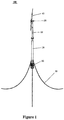
- Figure 1 is a stereogram of an offshore wind turbine with a spar type floating foundation using a motion suppression device according to a first embodiment of the present application.
- Figure 2 is a stereogram of the motion suppression device according to the first embodiment of the present application.
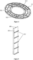
- Figure 3 and Figure 4 are, respectively, a plan view and a stereogram of a stabilizing plate of the motion suppression device in Figure 2 .
- Figure 5 is a stereogram of a fin stabilizer of the motion suppression device in Figure 2 .
- An offshore wind turbine with a spar-type floating foundation is taken as an example to describe the motion suppression device according to the first embodiment of the present application.
- an offshore wind turbine 100 with a spar type floating foundation mainly includes a spar type floating foundation 10, a motion suppression device 20, a mooring device 30, a blade 40, a nacelle 50 and a tower 60.
- the motion suppression device 20 is installed surrounding the floating foundation 10 and configured to reduce an overall motion magnitude of the offshore wind turbine 100
- the mooring device 30 is configured to pull the floating foundation 10 and anchor it to the seabed to avoid substantial movement or overturn of the offshore wind turbine 100
- the blade 40 is configured to receive wind energy and rotate to drive a rotor in the nacelle 50 to rotate so as to generate electrical energy
- the tower 60 is installed on the floating foundation 10 to support the blade 40 and the nacelle 50.
- the motion suppression device 20 includes an annular stabilizing plate 21 connected to the floating foundation 10.
- the annular stabilizing plate 21 is arranged horizontally surrounding an underwater portion of the floating foundation 10, and may have a circular ring shape or a polygonal shape with a circular inner hole.
- the stabilizing plate 21 may be formed as a planar surface or a curved surface.
- the stabilizing plate is arranged around the floating foundation, which may effectively increase the damping against the rolling, pitching and heaving of the floating foundation, thereby reducing the motion magnitude of the floating wind turbine.
- a plurality of circular or elliptical spoiler holes 213 may be uniformly arranged on the stabilizing plate 21.
- the vertical flow of fluid may be disturbed by the provided spoiler holes 213, which may effectively increase the damping against the heaving of the floating foundation, and further reduce the motion magnitude of the floating wind turbine.
- the stabilizing plate 21 has a permeability of 5% to 30% due to the spoiler holes 213, the stabilizing plate 21 may increase the damping against the heaving of the floating foundation more effectively.
- a permeability of 8% to 12% may achieve the best effect.
- the spoiler hole 213 may be of other shapes, for example triangle, square, diamond, and trapezoid.
- multiple turns of reinforcing flat steel may be arranged on the stabilizing plate 21 circumferentially to function as circular stiffeners 211, for example three turns of reinforcing flat steel may be arranged.
- a radial stiffener 212 may be arranged on the stabilizing plate 21 radially, for example six radial stiffeners may be arranged.
- a periphery of the stabilizing plate 21 may be provided with a flanging or a stiffener (not shown) to improve the strength of the stabilizing plate 21.
- fin stabilizers 22 may be arranged vertically around the floating foundation on the horizontal stabilizing plate 21 and spaced apart from each other. Two groups of the fin stabilizers 22 may be respectively arranged on and below the horizontal stabilizing plate 21. However, the present application is not limited to this.
- the fin stabilizers 22 may be arranged only on the horizontal stabilizing plate 21 or only below the horizontal stabilizing plate 21. Preferably, the fin stabilizers 22 are uniformly spaced apart from each other.
- a plurality of fin stabilizers 22 may be evenly arranged both on and below the stabilizing plate 21, and the number of the fin stabilizers 22 ranges from 4 to 10 (for example, may be 6 or 8).
- each fin stabilizer 22 on the stabilizing plate and each fin stabilizer 22 below the stabilizing plate are, respectively, deflected by an angle ⁇ and an angle ⁇ with respect to a radial direction of the floating foundation (or with respect to a straight line passing through a centre of the floating foundation and an inner endpoint of the fin stabilizer).
- the angle ⁇ and ⁇ may both be greater than 0 degree and less than 45 degree, and more preferably, the angle ⁇ and ⁇ may both in a range of 5 degree to 10 degree.
- the angle ⁇ and the angle ⁇ are equal.
- the angel ⁇ and the angle ⁇ may be unequal. It has been proven in practice that, when six fin stabilizers 22 are provided in one group, the fin stabilizers with a deflection angle of 10 degree may produce a good stabilizing result. More preferably, the upper fin stabilizers 22 arranged on the stabilizing plate and the lower fin stabilizers 22 arranged below the stabilizing plate are deflected in opposite directions. Due to the deflection of the fin stabilizers 22, the fluid flow about an axis Z is subject to a higher damping effect, which effectively increases the yawing damping and added mass of the floating foundation.
- the yawing magnitude of the floating foundation may be significantly reduced both clockwise and anticlockwise.
- the radial stiffeners 212 may also be deflected by an angle identical or substantially identical to that of the fin stabilizers 22.
- each fin stabilizer 22 extends vertically and has an L-shaped cross section. As shown in Figure 5 , outer edges of the fin stabilizer 22 are folded to form an L-shaped edgefold 223 to increase the structural stiffness and make the structure of the whole motion suppression device 20 more secure and reliable.
- the outer edges of the fin stabilizer 22 may also be reinforced by flat steel instead of forming the L-shaped cross section, and in this way, the structure of the whole motion suppression device 22 may also be more secure and reliable.
- outer sides of the fin stabilizers 22 on and below the horizontal stabilizing plate 21 may be connected, and inner sides of all the fin stabilizers 22 may be connected to the floating foundation 10 (for example, by welding or bolting).
- an annular member 23 may be provided to connect the outer sides of ends, far from the horizontal stabilizing plate 21 (i.e. upper ends), of the upper fin stabilizers 22, and an annular member 24 may be provided to connect the outer sides of ends, far from the horizontal stabilizing plate 21 (i.e. bottom ends), of the lower fin stabilizers.
- the present application is not limited to this.
- the annular members 23 and 24 may connect the fin stabilizers 22 at their inner sides or pass through the fin stabilizers 22 to connect them.
- the present application may install more annular members in various manners and arrange different annular members at different locations on the fin stabilizers (for example, one annular member may be provided to connect the fin stabilizers at the inner sides or the outer sides, and another annular member may be provided to pass through the fin stabilizers to connect them).
- the annular members 23 and 24 may be composed of circular tubes, square tubes or steel sheets, and may have a circular or polygonal shape.
- each fin stabilizer 22 may be provided with horizontal stiffeners 221, vertical stiffeners 222, or inclined or bent stiffeners (not shown) to enhance the structural stiffness of the fin stabilizer 22.
- the fin stabilizer 22 in the embodiment shown in Figure 5 is rectangular, the present application is not limited to this, and the fin stabilizer 22 may also in other flat shapes, such as triangle or trapezoid, or have a curved surface.
- a radial width of the stabilizing plate 21 may be equal to a width of the fin stabilizer 22.
- the width of the fin stabilizer 22 may vary with the diameter of the floating foundation 10.
- the outer edges of the fin stabilizers 22 are flush with an outer edge of the stabilizing plate 21. Obviously, it is allowed that the outer edges of the fin stabilizers 22 are not flush with the outer edge of the stabilizing plate 21.
- the inner edges of the fin stabilizers 22 are preferably flush with an inner edge of the stabilizing plate 21.
- the motion suppression device with two layers of fin stabilizers arranged on and below the stabilizing plate is described above in conjunction with Figures 1 to 6 .
- the present application is not limited to this, for example one or more stabilizing plates may be provided, and one or more layers of fin stabilizers may be provided.
- the whole motion suppression device is made of steel.
- routine maintenance is not required since the wind turbine is secured to the floating foundation when the wind turbine is built.
- Figure 6 illustrates a wind turbine 200 with a large floating foundation 10'. Due to its large size, the floating foundation may be partially submerged in the seawater, thus being referred to as a semi-submersible foundation.
- the wind turbine 200 has basically the same structure as the wind turbine 100, thus other parts of the wind turbine will not be described in detail herein.
- the floating foundation 10' is octagonal, and correspondingly, the motion suppression device 20' surrounding the floating foundation 10' includes an annular stabilizing plate 21' arranged octagonally and two layers of fin stabilizers, respectively, arranged on and below the stabilizing plate 21'. Similar to the first embodiment, in the second embodiment, circular spoiler holes may be provided on the stabilizing plate 21'.
- the stabilizing plate 21' may be provided with flat steel functioning as circular stiffeners 211' and radial stiffeners 212', and the fin stabilizer 22' may be provided with flat steel or a flanging functioning as stiffeners, so as to enhance the structural strength of the motion suppression device 20' and improve the shake-reducing effect thereof.
- the motion suppression device in the present application is also applicable to semi-submersible floating foundations in other shapes, for example circular, square, pentagon, hexagon or other polygonal shapes.
- the embodiments of the present application may increase the damping against rolling, pitching, and heaving of the floating wind turbine foundation by arranging the stabilizing plate along the periphery of the floating foundation, and increase the yawing damping and added mass of the floating foundation by arranging fin stabilizers on the stabilizing plate. Additionally, spoiler holes may be provided on the stabilizing plate to disturb the vertical flow of fluid, so as to increase the heaving damping of the floating foundation.
- the motion suppression device of the present application may reduce the motion magnitude of the floating foundation in any direction.
- the yawing magnitude of the floating foundation may be effectively reduced by setting the two layers of fin stabilizers which deflect in opposite directions.
- the motion suppression device is made of conventional steel and has a simple structure, and is effective for mitigating the motion of the whole floating offshore wind turbine.
- the motion suppression device according to the embodiments of the present application is featured by low cost, easy fabrication and availability, which may be used for various types of floating wind turbine foundations.
Landscapes
- Engineering & Computer Science (AREA)
- Chemical & Material Sciences (AREA)
- Combustion & Propulsion (AREA)
- Mechanical Engineering (AREA)
- Sustainable Development (AREA)
- Life Sciences & Earth Sciences (AREA)
- Sustainable Energy (AREA)
- General Engineering & Computer Science (AREA)
- Ocean & Marine Engineering (AREA)
- Architecture (AREA)
- Civil Engineering (AREA)
- Structural Engineering (AREA)
- Wind Motors (AREA)
Description
- The present application relates to an offshore wind turbine, and particularly to a motion suppression device for a floating offshore wind turbine configured to suppress the swinging motion of the offshore wind turbine around a vertical axis, and a floating foundation for the offshore wind turbine having the motion suppression device for the offshore wind turbine.
- An offshore wind turbine generally employs a gravity foundation, a monopile foundation, a jacket foundation, a tripod foundation, a suction caisson foundation, or a floating foundation according to a depth of seawater and seabed geological conditions. Among all these foundation types, the floating foundation is not restricted by the seabed conditions and is applicable to an offshore wind farm having a water depth greater than 50 meters, thus the floating foundation is a promising technique which has a bright prospect for wide application.
- Floating platforms in the marine industry and the offshore oil industry are similar to the floating foundation for the offshore wind turbine.
- At present, an anti-roll device in the marine industry mainly includes a fin stabilizer, a bilge keel, an anti-roll tank, an anti-roll rudder, and so on, and the fin stabilizer, the bilge keel, and the anti-roll rudder may keep the ship stable by using the lift force of fluid acting on these structures during the navigation. The faster the ship travels the more stable the ship is. The anti-roll tank may keep the ship stable by using a pressure difference between ballast water in side tanks of larboard and starboard to offset an overturning moment of the ship.
- A motion suppression device for the floating platform of the offshore oil projects mainly includes a damping plate for truss-spar and a stabilizing plate for floating bodies such as an FPSO.
- However, the foundation for the floating offshore wind turbine bears loads quite different from the floating platforms in the traditional marine industry and offshore oil industry. In addition to combined loads from wind and wave, the foundation for the floating offshore wind turbine is also subject to a gyro revolving effect resulting from the operation of the wind turbine of a high-rise structure. The gyro revolving effect may generate overturning moments Mx and My and a torque Mz about a vertical axis on the foundation, and cause violent motions of the whole wind turbine in six degrees of freedom, including axial motions along axes X, Y, and Z and swinging motions about these axes, which may bring a tremendous challenge for a pitch and yaw control system of the wind turbine, and adversely affect the normal operation of the wind turbine, reduce the generated energy, or even endanger the structural safety of the whole system.
- The foundation for the floating wind turbine is structurally different from the floating platform in the marine industry, and the loads, produced in the operation of machines carried on the foundation for the floating wind turbine is also different from that of the floating platform in the marine industry. At present, there is no effective motion suppression device specifically designed for overall motion of the floating offshore wind turbine. Therefore, it is necessary to provide a device for suppressing the motion of the floating wind turbine in six degrees of freedom.
-
EP 1 719 697 A1 refers to a motion suppression device for marine structure by which motions of a marine structure can be sufficiently reduced. The motion suppression device for marine structure comprises: a floating marine structure of cylindrical shape, an overhang structure fitted to a side wall of the floating marine structure at a position below the sea level and above a lower end of the side wall of the floating marine structure, a surrounding wall arranged at least below or above the overhang structure and a communication opening formed between the overhang structure and surrounding wall. -
US 4 982 681 A discusses a disc-shaped marine structure fabricated of steel and/or concrete. It is said to be able to support useful loads as great as 125,000 tonnes, and to be tethered to float stably in very deep water, with only minor response motions to wave of large amplitude and long period. -
CN 1 857 961 A relates to a shake-reducing device for marine float including one turn of shake-reducing plates with upwards L-shaped outer edge in the bottom of float, one group of supporting plates connecting the shake-reducing plate to the float and set in some interval, one group of flow disturbing ports in the side near the float of the shake-reducing plates, and 1-3 turns of stiffening L bars in the far side of the shake-reducing plates. - The present application intends to provide a motion suppression device for suppressing the motion of a floating offshore wind turbine, and a floating foundation for the offshore wind turbine having the motion suppression device.
- A motion suppression device for a floating offshore wind turbine is provided, wherein the floating offshore wind turbine has a floating foundation, and the motion suppression device includes at least one annular stabilizing plate arranged horizontally surrounding the floating foundation.
- The stabilizing plate is provided with a plurality of fin stabilizers including a first group of fin stabilizers arranged on one side of the stabilizing plate, and the first group of fin stabilizers are arranged vertically surrounding the floating foundation and spaced apart from each other.
- The plurality of fin stabilizers further include a second group of fin stabilizers arranged on the other side of the stabilizing plate, and the second group of fin stabilizers are arranged vertically surrounding the floating foundation and spaced apart from each other.
- Each fin stabilizer in the first group is deflected by a first angle in a width direction with respect to a straight line passing through a center of the floating foundation and an inner endpoint of the fin stabilizer.
- Each fin stabilizer in the first group is deflected by a first angle in a width direction with respect to a straight line passing through a center of the floating foundation and an inner endpoint of the fin stabilizer, and each fin stabilizer in the second group is deflected by a second angle in a width direction with respect to the straight line passing through the center of the floating foundation and the inner endpoint of the fin stabilizer.
- The first angle and the second angle may be equal.
- A deflection direction of the first group of fin stabilizers may be opposite to a deflection direction of the second group of fin stabilizers.
- The first angle may be greater than 0 degree and less than 45 degree, preferably range from 5 degree to 10 degree.
- The first angle may be greater than 0 degree and less than 45 degree, and the second angle may range from 1 degree to 15 degree.
- The first angle may range from 5 degree to 10 degree and the second angle may range from 5 degree to 10 degree.
- The fin stabilizers may each have an L-shaped cross section.
- The fin stabilizers may each be provided with a stiffener.
- The fin stabilizers may have a flat surface or a curved surface.
- The stiffener of the fin stabilizer may include at least one of a horizontal stiffener, an inclined stiffener, or a vertical stiffener.
- A stiffener may be provided on a surface of the stabilizing plate.
- The stabilizing plate may have a flat surface or a curved surface.
- The stabilizing plate may be provided with evenly distributed spoiler holes.
- A permeability, caused by the spoiler holes, of the stabilizing plate may range from 5% to 30%.
- A permeability, caused by the spoiler holes, of the stabilizing plate may range from 8% to 12%.
- The fin stabilizers in the first group are connected by an annular member.
- The fin stabilizers in the first group and the fin stabilizers in the second group may be both connected by an annular member.
- The annular member may have a polygonal or circular shape.
- The annular member may be formed by a square tube, a circular tube or a steel sheet.
- The annular member may be provided to connect outer sides of ends, far away from the stabilizing plate, of the fin stabilizers and/or the annular member may pass through the fin stabilizers.
- Inner sides of the fin stabilizers may be secured to the floating foundation.
- A floating foundation for an offshore wind turbine is further provided according to the present application, and the floating foundation may be provided with the motion suppression device for the floating offshore wind turbine.
- The floating foundation may be of a spar type or a semi-submersible type.
- The above and other objects and features of the present application will become more clearly based on the following description in conjunction with the accompanying drawings.
-
Figure 1 is a stereogram of an offshore wind turbine with a spar type floating foundation using a motion suppression device according to a first embodiment of the present application; -
Figure 2 is a stereogram of the motion suppression device according to the first embodiment of the present application; -
Figure 3 andFigure 4 are, respectively, a plan view and a stereogram of a stabilizing plate of the motion suppression device inFigure 2 ; -
Figure 5 is a stereogram of a fin stabilizer of the motion suppression device inFigure 2 ; -
Figure 6 is a stereogram of an offshore wind turbine with a semi-submersible floating foundation using a motion suppression device according to a second embodiment of the present application; and -
Figure 7 is a stereogram of the motion suppression device according to the second embodiment of the present application. - Embodiments of the present application will be described in detail below in conjunction with the accompanying drawings.
-
Figure 1 is a stereogram of an offshore wind turbine with a spar type floating foundation using a motion suppression device according to a first embodiment of the present application.Figure 2 is a stereogram of the motion suppression device according to the first embodiment of the present application.Figure 3 andFigure 4 are, respectively, a plan view and a stereogram of a stabilizing plate of the motion suppression device inFigure 2 .Figure 5 is a stereogram of a fin stabilizer of the motion suppression device inFigure 2 . - An offshore wind turbine with a spar-type floating foundation is taken as an example to describe the motion suppression device according to the first embodiment of the present application.
- As shown in
Figure 1 , anoffshore wind turbine 100 with a spar type floating foundation mainly includes a spartype floating foundation 10, amotion suppression device 20, amooring device 30, ablade 40, anacelle 50 and atower 60. Themotion suppression device 20 is installed surrounding the floatingfoundation 10 and configured to reduce an overall motion magnitude of theoffshore wind turbine 100, themooring device 30 is configured to pull the floatingfoundation 10 and anchor it to the seabed to avoid substantial movement or overturn of theoffshore wind turbine 100, theblade 40 is configured to receive wind energy and rotate to drive a rotor in thenacelle 50 to rotate so as to generate electrical energy, and thetower 60 is installed on the floatingfoundation 10 to support theblade 40 and thenacelle 50. - For simplicity and avoidance of vagueness of the subject matter of the present application, publicly known components will not be described herein. The structure and work principle of the motion suppression device according to the first embodiment of the present application will be described below in conjunction with
Figures 2 to 5 . - As shown in
Figure 2 , themotion suppression device 20 includes an annular stabilizingplate 21 connected to the floatingfoundation 10. As shown inFigure 1 , the annular stabilizingplate 21 is arranged horizontally surrounding an underwater portion of the floatingfoundation 10, and may have a circular ring shape or a polygonal shape with a circular inner hole. The stabilizingplate 21 may be formed as a planar surface or a curved surface. The stabilizing plate is arranged around the floating foundation, which may effectively increase the damping against the rolling, pitching and heaving of the floating foundation, thereby reducing the motion magnitude of the floating wind turbine. - As shown in
Figures 2 to 4 , a plurality of circular or elliptical spoiler holes 213 may be uniformly arranged on the stabilizingplate 21. The vertical flow of fluid may be disturbed by the providedspoiler holes 213, which may effectively increase the damping against the heaving of the floating foundation, and further reduce the motion magnitude of the floating wind turbine. When the stabilizingplate 21 has a permeability of 5% to 30% due to the spoiler holes 213, the stabilizingplate 21 may increase the damping against the heaving of the floating foundation more effectively. Preferably, a permeability of 8% to 12% may achieve the best effect. In addition, thespoiler hole 213 may be of other shapes, for example triangle, square, diamond, and trapezoid. - As shown in
Figure 3 , multiple turns of reinforcing flat steel may be arranged on the stabilizingplate 21 circumferentially to function ascircular stiffeners 211, for example three turns of reinforcing flat steel may be arranged. Apparently, aradial stiffener 212 may be arranged on the stabilizingplate 21 radially, for example six radial stiffeners may be arranged. In addition to thecircular stiffeners 211, a periphery of the stabilizingplate 21 may be provided with a flanging or a stiffener (not shown) to improve the strength of the stabilizingplate 21. - In addition, by arranging
fin stabilizers 22 around the floating foundation on the stabilizingplate 21, the yawing damping and added mass of the floating foundation may be effectively increased, which may mitigate the motion of the floating wind turbine. A plurality offin stabilizers 22 may be arranged vertically around the floating foundation on the horizontal stabilizingplate 21 and spaced apart from each other. Two groups of thefin stabilizers 22 may be respectively arranged on and below the horizontal stabilizingplate 21. However, the present application is not limited to this. The fin stabilizers 22 may be arranged only on the horizontal stabilizingplate 21 or only below the horizontal stabilizingplate 21. Preferably, thefin stabilizers 22 are uniformly spaced apart from each other. - For instance, a plurality of
fin stabilizers 22 may be evenly arranged both on and below the stabilizingplate 21, and the number of thefin stabilizers 22 ranges from 4 to 10 (for example, may be 6 or 8). Preferably, eachfin stabilizer 22 on the stabilizing plate and eachfin stabilizer 22 below the stabilizing plate are, respectively, deflected by an angle α and an angle β with respect to a radial direction of the floating foundation (or with respect to a straight line passing through a centre of the floating foundation and an inner endpoint of the fin stabilizer). Preferably, the angle α and β may both be greater than 0 degree and less than 45 degree, and more preferably, the angle α and β may both in a range of 5 degree to 10 degree. Preferably, the angle α and the angle β are equal. Of course, the angel α and the angle β may be unequal. It has been proven in practice that, when sixfin stabilizers 22 are provided in one group, the fin stabilizers with a deflection angle of 10 degree may produce a good stabilizing result. More preferably, theupper fin stabilizers 22 arranged on the stabilizing plate and thelower fin stabilizers 22 arranged below the stabilizing plate are deflected in opposite directions. Due to the deflection of thefin stabilizers 22, the fluid flow about an axis Z is subject to a higher damping effect, which effectively increases the yawing damping and added mass of the floating foundation. Additionally, since the upper fin stabilizers and the lower fin stabilizers are deflected in different directions, the yawing magnitude of the floating foundation may be significantly reduced both clockwise and anticlockwise. To adapt to the deflection angle of thefin stabilizers 22, theradial stiffeners 212 may also be deflected by an angle identical or substantially identical to that of thefin stabilizers 22. - As shown in
Figures 2 ,3 and5 , eachfin stabilizer 22 extends vertically and has an L-shaped cross section. As shown inFigure 5 , outer edges of thefin stabilizer 22 are folded to form an L-shapededgefold 223 to increase the structural stiffness and make the structure of the wholemotion suppression device 20 more secure and reliable. However, the present application is not limited to this. The outer edges of thefin stabilizer 22 may also be reinforced by flat steel instead of forming the L-shaped cross section, and in this way, the structure of the wholemotion suppression device 22 may also be more secure and reliable. - To improve the overall performance and reliability of the
motion suppression device 20, outer sides of thefin stabilizers 22 on and below the horizontal stabilizingplate 21 may be connected, and inner sides of all thefin stabilizers 22 may be connected to the floating foundation 10 (for example, by welding or bolting). Preferably, as shown inFigures 2 and3 , anannular member 23 may be provided to connect the outer sides of ends, far from the horizontal stabilizing plate 21 (i.e. upper ends), of theupper fin stabilizers 22, and anannular member 24 may be provided to connect the outer sides of ends, far from the horizontal stabilizing plate 21 (i.e. bottom ends), of the lower fin stabilizers. However, the present application is not limited to this. For instance, theannular members fin stabilizers 22 at their inner sides or pass through thefin stabilizers 22 to connect them. The present application may install more annular members in various manners and arrange different annular members at different locations on the fin stabilizers (for example, one annular member may be provided to connect the fin stabilizers at the inner sides or the outer sides, and another annular member may be provided to pass through the fin stabilizers to connect them). Theannular members - To further improve the stiffness of the motion suppression device, as shown in
Figure 5 , a side surface of eachfin stabilizer 22 may be provided withhorizontal stiffeners 221,vertical stiffeners 222, or inclined or bent stiffeners (not shown) to enhance the structural stiffness of thefin stabilizer 22. - Although the
fin stabilizer 22 in the embodiment shown inFigure 5 is rectangular, the present application is not limited to this, and thefin stabilizer 22 may also in other flat shapes, such as triangle or trapezoid, or have a curved surface. If the floating foundation with themotion suppression device 20 has a uniform diameter, a radial width of the stabilizingplate 21 may be equal to a width of thefin stabilizer 22. If the floating foundation with themotion suppression device 20 has a non-uniform diameter, the width of thefin stabilizer 22 may vary with the diameter of the floatingfoundation 10. Preferably, the outer edges of thefin stabilizers 22 are flush with an outer edge of the stabilizingplate 21. Obviously, it is allowed that the outer edges of thefin stabilizers 22 are not flush with the outer edge of the stabilizingplate 21. In addition, the inner edges of thefin stabilizers 22 are preferably flush with an inner edge of the stabilizingplate 21. - The motion suppression device with two layers of fin stabilizers arranged on and below the stabilizing plate is described above in conjunction with
Figures 1 to 6 . However, the present application is not limited to this, for example one or more stabilizing plates may be provided, and one or more layers of fin stabilizers may be provided. - In the above embodiment, the whole motion suppression device is made of steel. For the wind turbine with a spar type floating foundation shown in
Figure 1 , routine maintenance is not required since the wind turbine is secured to the floating foundation when the wind turbine is built. - The motion suppression device according to a second embodiment of the present application is described below in conjunction with
Figures 6 and7 . -
Figure 6 illustrates awind turbine 200 with a large floating foundation 10'. Due to its large size, the floating foundation may be partially submerged in the seawater, thus being referred to as a semi-submersible foundation. - Except the floating foundation 10' and a motion suppression device 20', the
wind turbine 200 has basically the same structure as thewind turbine 100, thus other parts of the wind turbine will not be described in detail herein. - As shown in
Figures 6 and7 , the floating foundation 10' is octagonal, and correspondingly, the motion suppression device 20' surrounding the floating foundation 10' includes an annular stabilizing plate 21' arranged octagonally and two layers of fin stabilizers, respectively, arranged on and below the stabilizing plate 21'. Similar to the first embodiment, in the second embodiment, circular spoiler holes may be provided on the stabilizing plate 21'. In addition, like the first embodiment, in the second embodiment, the stabilizing plate 21' may be provided with flat steel functioning as circular stiffeners 211' and radial stiffeners 212', and the fin stabilizer 22' may be provided with flat steel or a flanging functioning as stiffeners, so as to enhance the structural strength of the motion suppression device 20' and improve the shake-reducing effect thereof. - Although the floating foundation shown in
Figures 6 and7 is octagonal, the motion suppression device in the present application is also applicable to semi-submersible floating foundations in other shapes, for example circular, square, pentagon, hexagon or other polygonal shapes. - Based on the above description, it is clear that, the embodiments of the present application may increase the damping against rolling, pitching, and heaving of the floating wind turbine foundation by arranging the stabilizing plate along the periphery of the floating foundation, and increase the yawing damping and added mass of the floating foundation by arranging fin stabilizers on the stabilizing plate. Additionally, spoiler holes may be provided on the stabilizing plate to disturb the vertical flow of fluid, so as to increase the heaving damping of the floating foundation. In summary, the motion suppression device of the present application may reduce the motion magnitude of the floating foundation in any direction.
- Moreover, the yawing magnitude of the floating foundation may be effectively reduced by setting the two layers of fin stabilizers which deflect in opposite directions.
- The motion suppression device according to the embodiments of the present application is made of conventional steel and has a simple structure, and is effective for mitigating the motion of the whole floating offshore wind turbine.
- Further, the motion suppression device according to the embodiments of the present application is featured by low cost, easy fabrication and availability, which may be used for various types of floating wind turbine foundations.
Claims (16)
- A floating offshore wind turbine (100), having a floating foundation (10) and a motion
suppression device (20),
wherein the motion suppression device comprises at least one annular stabilizing plate (21)
attached to the floating foundation and arranged horizontally surrounding the floating foundation; and the stabilizing plate is provided with a plurality of fin stabilizers (22)
comprising a first group of fin stabilizers arranged on one side of the stabilizing plate, and the first group of fin stabilizers are arranged vertically surrounding the floating foundation (10) and
spaced apart from each other, wherein each fin stabilizer in the first group is deflected in a horizontal plane by a first angle (α)
in a width direction with respect to a straight line passing through a center of the floating foundation and an inner endpoint of the fin stabilizer, and the first angle (α)
is greater than 0 degree and less than 45 degree. - The floating offshore wind turbine according to Claim 1, wherein the plurality of fin stabilizers (22)
further comprise a second group of fin stabilizers arranged on the other side of the stabilizing plate, and the second group of fin stabilizers are arranged vertically surrounding the floating foundation and spaced apart from each other. - The floating offshore wind turbine-according to Claim 2, wherein each fin stabilizer (22) in
the second group is deflected in a horizontal plane by a second angle (β)
in a width direction with
respect to the straight line passing through the center of the floating foundation and the inner endpoint of the fin stabilizer, and both the first angle and the second angle are greater than 0 degree and less than 45 degree. - The floating offshore wind turbine according to Claim 3, wherein the first angle (α) and
the second angle (β) are equal. - The floating offshore wind turbine according to Claim 1, wherein the first angle ranges from 5 degree to 10 degree.
- The floating offshore wind turbine according to Claim 3 or Claim 4, wherein both the first angle and the second angle range from 5 degree to 10 degree.
- The floating offshore wind turbine according to any one of Claims 1 to 4, wherein the fin stabilizers (22) each have an L-shaped cross section.
- The floating offshore wind turbine according to any one of Claims 1 to 4, wherein the fin stabilizers are each provided with a stiffener (221,222).
- The floating offshore wind turbine according to any one of Claims 1 to 4, wherein a stiffener is provided on a surface of the stabilizing plate.
- The floating offshore wind turbine according to any one of Claims 1 to 4, wherein the stabilizing plate is provided with evenly distributed spoiler holes (213)
- The floating offshore wind turbine according to Claim 10, wherein a permeability, caused by the spoiler holes, of the stabilizing plate ranges from 5% to 30%.
- The floating offshore wind turbine according to Claim 10, wherein a permeability, caused by the spoiler holes, of the stabilizing plate ranges from 8% to 12%.
- The floating offshore wind turbine according to Claim 1, wherein the fin stabilizers in the first group are connected by an annular member.
- The floating offshore wind turbine according to Claim 2, wherein the fin stabilizers in the first group and the fin stabilizers in the second group are both connected by an annular member (23,24).
- The floating offshore wind turbine according to Claim 13 or Claim 14, wherein the annular member is provided to connect outer sides of ends, far away from the stabilizing plate, of the fin stabilizers and/or the annular member passes through the fin stabilizers.
- The floating offshore wind turbine according to any one of Claims 1 to 4, Claim 13 or Claim 14, wherein inner sides of the fin stabilizers are secured to the floating foundation.
Applications Claiming Priority (2)
| Application Number | Priority Date | Filing Date | Title |
|---|---|---|---|
| CN201110440041.9A CN102490876B (en) | 2011-12-23 | 2011-12-23 | Floating offshore wind turbine movement suppression device and floating base for offshore wind turbine |
| PCT/CN2012/087142 WO2013091567A1 (en) | 2011-12-23 | 2012-12-21 | Movement inhibiting apparatus for floating offshore wind turbine and floating base used for offshore wind turbine |
Publications (3)
| Publication Number | Publication Date |
|---|---|
| EP2796362A1 EP2796362A1 (en) | 2014-10-29 |
| EP2796362A4 EP2796362A4 (en) | 2015-08-12 |
| EP2796362B1 true EP2796362B1 (en) | 2019-03-20 |
Family
ID=46182748
Family Applications (1)
| Application Number | Title | Priority Date | Filing Date |
|---|---|---|---|
| EP12861025.0A Active EP2796362B1 (en) | 2011-12-23 | 2012-12-21 | Movement inhibiting apparatus for floating offshore wind turbine and floating base used for offshore wind turbine |
Country Status (7)
| Country | Link |
|---|---|
| US (1) | US9316209B2 (en) |
| EP (1) | EP2796362B1 (en) |
| CN (1) | CN102490876B (en) |
| AU (1) | AU2012357247C1 (en) |
| DK (1) | DK2796362T3 (en) |
| ES (1) | ES2719800T3 (en) |
| WO (1) | WO2013091567A1 (en) |
Families Citing this family (37)
| Publication number | Priority date | Publication date | Assignee | Title |
|---|---|---|---|---|
| CN102490876B (en) | 2011-12-23 | 2014-04-02 | 新疆金风科技股份有限公司 | Floating offshore wind turbine movement suppression device and floating base for offshore wind turbine |
| CN106416056A (en) * | 2014-04-09 | 2017-02-15 | W太阳能有限公司 | Floating body of photovoltaic power generation device on water and connection method between floating bodies |
| KR101601025B1 (en) * | 2014-12-01 | 2016-03-21 | 한국해양과학기술원 | Motion attenuating platform for offshore structures and marine semi-submersible structures equipped with it |
| AU2016279059B2 (en) * | 2015-06-19 | 2021-02-04 | Principle Power, Inc | Floating wind turbine platform structure with optimized transfer of wave and wind loads |
| FR3052194A3 (en) * | 2016-06-03 | 2017-12-08 | Dietswell | FLOATING EOLIANS. |
| FR3054523B1 (en) * | 2016-07-26 | 2018-07-27 | Ifp Energies Now | FLOATING SUPPORT COMPRISING A FLOAT AND A DAMPING PLATE HAVING A ROW OF ORIFICES |
| FR3054522B1 (en) * | 2016-07-26 | 2019-04-05 | IFP Energies Nouvelles | FLOATING SUPPORT COMPRISING A FLOAT AND A DAMPING PLATE WITH VARIABLE SECTION WITH DEPTH |
| JP2018090088A (en) * | 2016-12-02 | 2018-06-14 | 日立造船株式会社 | Lifting body and floating structure |
| CN107499468B (en) * | 2017-09-06 | 2024-02-06 | 大连理工大学 | Single column type platform |
| CN109931226B (en) * | 2017-12-15 | 2021-03-23 | 上海海事大学 | Vertical resistance-increasing combined type offshore wind turbine supporting structure system |
| EP3502353B1 (en) * | 2017-12-22 | 2021-04-21 | Siemens Gamesa Renewable Energy A/S | Foundation building system for an offshore wind turbine and method for installation of an offshore wind turbine |
| CN108385708B (en) * | 2018-02-06 | 2020-06-23 | 重庆大学 | A floating infrastructure system for offshore wind turbines with dual anti-sway mechanisms |
| CN108301954A (en) * | 2018-03-21 | 2018-07-20 | 山东科技大学 | Ocean wind-powered electricity generation stake ocean current vibration absorber |
| WO2019222825A1 (en) * | 2018-05-24 | 2019-11-28 | Horton Do Brasil Tecnologia Offshore, Ltda. | Offshore spar structure with hydrodynamic dampers and methods for deploying and installing same |
| CN109162865B (en) * | 2018-08-10 | 2021-02-26 | 鹤壁市科技创新研究院 | Assembled and combined type wind power generation device and power generation method thereof |
| CN109267668A (en) * | 2018-11-16 | 2019-01-25 | 郑州大学 | A kind of broken whirlpool device of the spin inhibiting steel pipe tall and slender structure vortex-induced vibration |
| US11939032B2 (en) | 2019-02-21 | 2024-03-26 | Vl Offshore, Llc | Floating-type foundation for supporting a wind power generation system and including a stabilized power cable, system of floating-type foundations, and a method of stabilizing the power cable |
| US11014637B2 (en) * | 2019-02-21 | 2021-05-25 | Vl Offshore, Llc | Motion-attenuated semi-submersible floating-type foundation for supporting a wind power generation system |
| CN111022269B (en) * | 2019-11-12 | 2021-10-15 | 中国能源建设集团广东省电力设计研究院有限公司 | Offshore foundation structure and offshore wind turbine system |
| CN112046699B (en) * | 2020-06-17 | 2024-08-09 | 大连理工大学 | Marine floating wind-driven generator platform stabilizer |
| CN112339926B (en) * | 2020-11-03 | 2022-01-25 | 阳光学院 | Floating anti-collision structure for offshore wind turbine foundation |
| CN112594140B (en) * | 2020-12-30 | 2025-01-24 | 中国华能集团清洁能源技术研究院有限公司 | Floating wind turbine foundation and wind turbine generator set using trough-type anti-rolling water tank |
| EP4063643A1 (en) * | 2021-03-22 | 2022-09-28 | Siemens Gamesa Renewable Energy A/S | Method and device of controlling an operation of a floating wind turbine |
| CN113148042B (en) * | 2021-05-06 | 2026-01-30 | 西安热工研究院有限公司 | A floating body for a floating photovoltaic power station |
| CN113107748B (en) * | 2021-05-14 | 2022-08-26 | 江苏科技大学 | Offshore floating type power generation device with wind and wave energy mixed utilization |
| CN113086116B (en) * | 2021-05-19 | 2024-07-26 | 中国船舶重工集团海装风电股份有限公司 | Floating wind power platform |
| CN113586318B (en) * | 2021-09-03 | 2025-03-25 | 中国华能集团清洁能源技术研究院有限公司 | A single-column floating offshore integrated power platform |
| CN113772034A (en) * | 2021-09-06 | 2021-12-10 | 上海电气风电集团股份有限公司 | Offshore wind turbine and foundation |
| EP4184005A1 (en) * | 2021-11-23 | 2023-05-24 | Siemens Gamesa Renewable Energy A/S | Cage for a monopile of an offshore wind turbine, tower for an offshore wind turbine, offshore wind turbine and method for installing a tower of an offshore wind turbine |
| CN114016488B (en) * | 2021-12-29 | 2023-02-28 | 江苏龙源振华海洋工程有限公司 | Offshore booster station jacket construction process |
| CN114604376A (en) * | 2022-02-17 | 2022-06-10 | 中国海洋石油集团有限公司 | Novel floating type fan foundation with box type heave plates |
| CN114455000B (en) * | 2022-03-10 | 2023-01-03 | 烟台大学 | Multi-floating body mooring device for floating ocean platform |
| JP2024011377A (en) * | 2022-07-14 | 2024-01-25 | 大成建設株式会社 | Construction method for vibration suppression members and floating structures |
| EP4382404A1 (en) * | 2022-12-09 | 2024-06-12 | Totalenergies Onetech | Method of manufacturing a floater, in particular a floater of a floating structure of an offshore wind turbine |
| CN115743441A (en) * | 2022-12-15 | 2023-03-07 | 天津绿动未来能源管理有限公司 | Self-rotation-preventing single-point anchoring system of marine floating type photovoltaic structure |
| CN119778180A (en) * | 2025-01-03 | 2025-04-08 | 浙江大学海南研究院 | Floating fan with anti-rolling function and control method thereof |
| CN120397185B (en) * | 2025-07-07 | 2025-09-30 | 香港理工大学深圳研究院 | Floating type wind power foundation and wind power equipment |
Family Cites Families (22)
| Publication number | Priority date | Publication date | Assignee | Title |
|---|---|---|---|---|
| US3224401A (en) * | 1964-04-13 | 1965-12-21 | Shell Oil Co | Stabilized floating drilling platform |
| US3224402A (en) | 1964-04-13 | 1965-12-21 | Shell Oil Co | Stabilized floating drilling platform |
| US3382834A (en) * | 1964-07-30 | 1968-05-14 | Mcmullen Ass John J | Ship stabilizer |
| US3299846A (en) * | 1965-01-18 | 1967-01-24 | Canadian Patents Dev | Stable floating support columns |
| US4004536A (en) | 1975-03-17 | 1977-01-25 | Claude Bernier | Anti-skid boat |
| JPS61119489A (en) | 1984-11-15 | 1986-06-06 | Mitsubishi Heavy Ind Ltd | Hull-rolling reducing apparatus |
| EP0184407B1 (en) * | 1984-12-04 | 1990-03-14 | Canadian Patents and Development Limited | Floating marine structure of thin disc form |
| NO300884B1 (en) * | 1995-12-06 | 1997-08-11 | Fred Olsen | Wave dampers for floating structures |
| US9003631B2 (en) * | 2003-10-23 | 2015-04-14 | Shigeyuki Yamamoto | Power generation assemblies and apparatus |
| JP4388548B2 (en) * | 2004-02-24 | 2009-12-24 | 三菱重工業株式会社 | Offshore structure vibration reduction device |
| CN1702319A (en) * | 2005-06-16 | 2005-11-30 | 孙正维 | Wind power, wave power and solar energy integrated generating set at shallow sea reef area |
| CN1857961A (en) * | 2006-05-10 | 2006-11-08 | 中国海洋石油总公司 | Marine float shake-reducing device |
| CN2900352Y (en) | 2006-05-10 | 2007-05-16 | 中国海洋石油总公司 | Float rocking reducing device on sea |
| ES2301445B1 (en) * | 2007-11-29 | 2009-08-17 | Acciona Energia S.A. | MARINE SYSTEM OF ELECTRICAL ENERGY PRODUCTION AND INSTALLATION METHOD. |
| CN101566130B (en) * | 2008-04-23 | 2010-12-22 | 中国科学院工程热物理研究所 | Anti-tilting suspended wind turbine unit |
| CN201347195Y (en) * | 2008-11-25 | 2009-11-18 | 中国海洋石油总公司 | Anti-rolling device of ocean floating body |
| CN101475048B (en) * | 2009-01-13 | 2011-08-10 | 中国海洋大学 | Novel sea deep water buoy platform |
| US8057127B2 (en) * | 2009-12-14 | 2011-11-15 | General Electric Company | Systems and methods for assembling an offshore support system for use with a wind turbine |
| CN102235011A (en) * | 2010-04-27 | 2011-11-09 | 南通大学 | Flexible floating foundation for offshore wind generating sets |
| CN102146873B (en) * | 2011-03-31 | 2013-01-09 | 上海交通大学 | Single column maritime wind power generation device with circumferential stabilizing column |
| CN102285429A (en) * | 2011-05-26 | 2011-12-21 | 天津大学 | Floating type supporting structure for marine windmill |
| CN102490876B (en) * | 2011-12-23 | 2014-04-02 | 新疆金风科技股份有限公司 | Floating offshore wind turbine movement suppression device and floating base for offshore wind turbine |
-
2011
- 2011-12-23 CN CN201110440041.9A patent/CN102490876B/en active Active
-
2012
- 2012-12-21 US US14/363,403 patent/US9316209B2/en active Active
- 2012-12-21 DK DK12861025.0T patent/DK2796362T3/en active
- 2012-12-21 ES ES12861025T patent/ES2719800T3/en active Active
- 2012-12-21 AU AU2012357247A patent/AU2012357247C1/en active Active
- 2012-12-21 WO PCT/CN2012/087142 patent/WO2013091567A1/en not_active Ceased
- 2012-12-21 EP EP12861025.0A patent/EP2796362B1/en active Active
Non-Patent Citations (1)
| Title |
|---|
| None * |
Also Published As
| Publication number | Publication date |
|---|---|
| CN102490876A (en) | 2012-06-13 |
| AU2012357247A1 (en) | 2014-06-19 |
| AU2012357247C1 (en) | 2016-03-24 |
| EP2796362A1 (en) | 2014-10-29 |
| US20140345510A1 (en) | 2014-11-27 |
| AU2012357247B2 (en) | 2015-05-28 |
| EP2796362A4 (en) | 2015-08-12 |
| DK2796362T3 (en) | 2019-05-13 |
| WO2013091567A1 (en) | 2013-06-27 |
| CN102490876B (en) | 2014-04-02 |
| US9316209B2 (en) | 2016-04-19 |
| ES2719800T3 (en) | 2019-07-16 |
Similar Documents
| Publication | Publication Date | Title |
|---|---|---|
| US9316209B2 (en) | Movement inhibiting apparatus for floating offshore wind turbine and floating base used for offshore wind turbine | |
| CN102758446B (en) | Semi-submersible type offshore floating wind turbine foundation | |
| KR102440200B1 (en) | FLOATING OFFSHORE PLATFORM | |
| EP3115600B1 (en) | Flare-type tensile legs floating wind turbine base, offshore wind turbine and construction method | |
| EP2684792B1 (en) | Spar type floating structure | |
| KR102294285B1 (en) | Floating, semi-submersible wind turbine platform | |
| CN102758447B (en) | Semi-submersible offshore floating fan foundation | |
| CN104401458B (en) | Semi-submersible type floating fan base and floating fan | |
| KR101933168B1 (en) | Column-stabilized offshore platform with water-entrapment plates and asymmetric mooring system for support of offshore wind turbines | |
| CN102765466B (en) | Semi-submersible offshore floating fan foundation | |
| CN112009634A (en) | Submersible active support structure in offshore installations | |
| CN204415681U (en) | Semi-submersible lng floating blower foundation and floating blower fan | |
| EP2789847B1 (en) | Floating type wind turbine generation apparatus and installation method thereof | |
| US12202574B2 (en) | Buoyant structure for receiving a tower of a wind turbine in offshore deployment | |
| JP2018526259A (en) | Floating wind turbine assembly and method for mooring such a floating wind turbine assembly | |
| WO2022231511A1 (en) | A buoyant structure for receiving a tower of a wind turbine in offshore deployment | |
| JP2019509934A (en) | Floating platform | |
| JP7569108B2 (en) | Offshore Power Generation System | |
| CN119773927B (en) | Floating fan foundation | |
| KR20240176120A (en) | Floating offshore wind turbine |
Legal Events
| Date | Code | Title | Description |
|---|---|---|---|
| PUAI | Public reference made under article 153(3) epc to a published international application that has entered the european phase |
Free format text: ORIGINAL CODE: 0009012 |
|
| 17P | Request for examination filed |
Effective date: 20140618 |
|
| AK | Designated contracting states |
Kind code of ref document: A1 Designated state(s): AL AT BE BG CH CY CZ DE DK EE ES FI FR GB GR HR HU IE IS IT LI LT LU LV MC MK MT NL NO PL PT RO RS SE SI SK SM TR |
|
| DAX | Request for extension of the european patent (deleted) | ||
| RA4 | Supplementary search report drawn up and despatched (corrected) |
Effective date: 20150715 |
|
| RIC1 | Information provided on ipc code assigned before grant |
Ipc: F03D 11/00 20060101ALI20150709BHEP Ipc: B63B 35/44 20060101ALI20150709BHEP Ipc: B63B 38/00 20060101AFI20150709BHEP Ipc: F03D 11/04 20060101ALI20150709BHEP Ipc: B63B 39/06 20060101ALI20150709BHEP |
|
| REG | Reference to a national code |
Ref country code: DE Ref legal event code: R079 Ref document number: 602012058147 Country of ref document: DE Free format text: PREVIOUS MAIN CLASS: B63B0038000000 Ipc: F03D0013000000 |
|
| GRAP | Despatch of communication of intention to grant a patent |
Free format text: ORIGINAL CODE: EPIDOSNIGR1 |
|
| STAA | Information on the status of an ep patent application or granted ep patent |
Free format text: STATUS: GRANT OF PATENT IS INTENDED |
|
| RIC1 | Information provided on ipc code assigned before grant |
Ipc: F03D 13/25 20160101ALI20180326BHEP Ipc: B63B 35/44 20060101ALI20180326BHEP Ipc: B63B 39/06 20060101ALI20180326BHEP Ipc: F03D 13/20 20160101ALI20180326BHEP Ipc: F03D 13/00 20160101AFI20180326BHEP |
|
| INTG | Intention to grant announced |
Effective date: 20180412 |
|
| GRAJ | Information related to disapproval of communication of intention to grant by the applicant or resumption of examination proceedings by the epo deleted |
Free format text: ORIGINAL CODE: EPIDOSDIGR1 |
|
| STAA | Information on the status of an ep patent application or granted ep patent |
Free format text: STATUS: REQUEST FOR EXAMINATION WAS MADE |
|
| INTC | Intention to grant announced (deleted) | ||
| GRAS | Grant fee paid |
Free format text: ORIGINAL CODE: EPIDOSNIGR3 |
|
| STAA | Information on the status of an ep patent application or granted ep patent |
Free format text: STATUS: GRANT OF PATENT IS INTENDED |
|
| GRAP | Despatch of communication of intention to grant a patent |
Free format text: ORIGINAL CODE: EPIDOSNIGR1 |
|
| INTG | Intention to grant announced |
Effective date: 20181102 |
|
| RIC1 | Information provided on ipc code assigned before grant |
Ipc: B63B 39/06 20060101ALI20180326BHEP Ipc: F03D 13/20 20160101ALI20180326BHEP Ipc: F03D 13/00 20160101AFI20180326BHEP Ipc: F03D 13/25 20160101ALI20180326BHEP Ipc: B63B 35/44 20060101ALI20180326BHEP |
|
| GRAA | (expected) grant |
Free format text: ORIGINAL CODE: 0009210 |
|
| STAA | Information on the status of an ep patent application or granted ep patent |
Free format text: STATUS: THE PATENT HAS BEEN GRANTED |
|
| AK | Designated contracting states |
Kind code of ref document: B1 Designated state(s): AL AT BE BG CH CY CZ DE DK EE ES FI FR GB GR HR HU IE IS IT LI LT LU LV MC MK MT NL NO PL PT RO RS SE SI SK SM TR |
|
| REG | Reference to a national code |
Ref country code: GB Ref legal event code: FG4D |
|
| REG | Reference to a national code |
Ref country code: CH Ref legal event code: EP |
|
| REG | Reference to a national code |
Ref country code: DE Ref legal event code: R096 Ref document number: 602012058147 Country of ref document: DE |
|
| REG | Reference to a national code |
Ref country code: AT Ref legal event code: REF Ref document number: 1110823 Country of ref document: AT Kind code of ref document: T Effective date: 20190415 |
|
| REG | Reference to a national code |
Ref country code: IE Ref legal event code: FG4D |
|
| REG | Reference to a national code |
Ref country code: DK Ref legal event code: T3 Effective date: 20190507 |
|
| REG | Reference to a national code |
Ref country code: ES Ref legal event code: FG2A Ref document number: 2719800 Country of ref document: ES Kind code of ref document: T3 Effective date: 20190716 |
|
| REG | Reference to a national code |
Ref country code: NL Ref legal event code: MP Effective date: 20190320 |
|
| PG25 | Lapsed in a contracting state [announced via postgrant information from national office to epo] |
Ref country code: LT Free format text: LAPSE BECAUSE OF FAILURE TO SUBMIT A TRANSLATION OF THE DESCRIPTION OR TO PAY THE FEE WITHIN THE PRESCRIBED TIME-LIMIT Effective date: 20190320 Ref country code: SE Free format text: LAPSE BECAUSE OF FAILURE TO SUBMIT A TRANSLATION OF THE DESCRIPTION OR TO PAY THE FEE WITHIN THE PRESCRIBED TIME-LIMIT Effective date: 20190320 Ref country code: FI Free format text: LAPSE BECAUSE OF FAILURE TO SUBMIT A TRANSLATION OF THE DESCRIPTION OR TO PAY THE FEE WITHIN THE PRESCRIBED TIME-LIMIT Effective date: 20190320 |
|
| REG | Reference to a national code |
Ref country code: LT Ref legal event code: MG4D |
|
| PG25 | Lapsed in a contracting state [announced via postgrant information from national office to epo] |
Ref country code: RS Free format text: LAPSE BECAUSE OF FAILURE TO SUBMIT A TRANSLATION OF THE DESCRIPTION OR TO PAY THE FEE WITHIN THE PRESCRIBED TIME-LIMIT Effective date: 20190320 Ref country code: NL Free format text: LAPSE BECAUSE OF FAILURE TO SUBMIT A TRANSLATION OF THE DESCRIPTION OR TO PAY THE FEE WITHIN THE PRESCRIBED TIME-LIMIT Effective date: 20190320 Ref country code: HR Free format text: LAPSE BECAUSE OF FAILURE TO SUBMIT A TRANSLATION OF THE DESCRIPTION OR TO PAY THE FEE WITHIN THE PRESCRIBED TIME-LIMIT Effective date: 20190320 Ref country code: LV Free format text: LAPSE BECAUSE OF FAILURE TO SUBMIT A TRANSLATION OF THE DESCRIPTION OR TO PAY THE FEE WITHIN THE PRESCRIBED TIME-LIMIT Effective date: 20190320 Ref country code: BG Free format text: LAPSE BECAUSE OF FAILURE TO SUBMIT A TRANSLATION OF THE DESCRIPTION OR TO PAY THE FEE WITHIN THE PRESCRIBED TIME-LIMIT Effective date: 20190620 Ref country code: GR Free format text: LAPSE BECAUSE OF FAILURE TO SUBMIT A TRANSLATION OF THE DESCRIPTION OR TO PAY THE FEE WITHIN THE PRESCRIBED TIME-LIMIT Effective date: 20190621 |
|
| REG | Reference to a national code |
Ref country code: NO Ref legal event code: T2 Effective date: 20190320 |
|
| REG | Reference to a national code |
Ref country code: AT Ref legal event code: MK05 Ref document number: 1110823 Country of ref document: AT Kind code of ref document: T Effective date: 20190320 |
|
| PG25 | Lapsed in a contracting state [announced via postgrant information from national office to epo] |
Ref country code: EE Free format text: LAPSE BECAUSE OF FAILURE TO SUBMIT A TRANSLATION OF THE DESCRIPTION OR TO PAY THE FEE WITHIN THE PRESCRIBED TIME-LIMIT Effective date: 20190320 Ref country code: SK Free format text: LAPSE BECAUSE OF FAILURE TO SUBMIT A TRANSLATION OF THE DESCRIPTION OR TO PAY THE FEE WITHIN THE PRESCRIBED TIME-LIMIT Effective date: 20190320 Ref country code: AL Free format text: LAPSE BECAUSE OF FAILURE TO SUBMIT A TRANSLATION OF THE DESCRIPTION OR TO PAY THE FEE WITHIN THE PRESCRIBED TIME-LIMIT Effective date: 20190320 Ref country code: PT Free format text: LAPSE BECAUSE OF FAILURE TO SUBMIT A TRANSLATION OF THE DESCRIPTION OR TO PAY THE FEE WITHIN THE PRESCRIBED TIME-LIMIT Effective date: 20190720 Ref country code: IT Free format text: LAPSE BECAUSE OF FAILURE TO SUBMIT A TRANSLATION OF THE DESCRIPTION OR TO PAY THE FEE WITHIN THE PRESCRIBED TIME-LIMIT Effective date: 20190320 Ref country code: CZ Free format text: LAPSE BECAUSE OF FAILURE TO SUBMIT A TRANSLATION OF THE DESCRIPTION OR TO PAY THE FEE WITHIN THE PRESCRIBED TIME-LIMIT Effective date: 20190320 Ref country code: RO Free format text: LAPSE BECAUSE OF FAILURE TO SUBMIT A TRANSLATION OF THE DESCRIPTION OR TO PAY THE FEE WITHIN THE PRESCRIBED TIME-LIMIT Effective date: 20190320 |
|
| PG25 | Lapsed in a contracting state [announced via postgrant information from national office to epo] |
Ref country code: SM Free format text: LAPSE BECAUSE OF FAILURE TO SUBMIT A TRANSLATION OF THE DESCRIPTION OR TO PAY THE FEE WITHIN THE PRESCRIBED TIME-LIMIT Effective date: 20190320 Ref country code: PL Free format text: LAPSE BECAUSE OF FAILURE TO SUBMIT A TRANSLATION OF THE DESCRIPTION OR TO PAY THE FEE WITHIN THE PRESCRIBED TIME-LIMIT Effective date: 20190320 |
|
| PG25 | Lapsed in a contracting state [announced via postgrant information from national office to epo] |
Ref country code: AT Free format text: LAPSE BECAUSE OF FAILURE TO SUBMIT A TRANSLATION OF THE DESCRIPTION OR TO PAY THE FEE WITHIN THE PRESCRIBED TIME-LIMIT Effective date: 20190320 Ref country code: IS Free format text: LAPSE BECAUSE OF FAILURE TO SUBMIT A TRANSLATION OF THE DESCRIPTION OR TO PAY THE FEE WITHIN THE PRESCRIBED TIME-LIMIT Effective date: 20190720 |
|
| REG | Reference to a national code |
Ref country code: DE Ref legal event code: R097 Ref document number: 602012058147 Country of ref document: DE |
|
| PLBE | No opposition filed within time limit |
Free format text: ORIGINAL CODE: 0009261 |
|
| STAA | Information on the status of an ep patent application or granted ep patent |
Free format text: STATUS: NO OPPOSITION FILED WITHIN TIME LIMIT |
|
| 26N | No opposition filed |
Effective date: 20200102 |
|
| PG25 | Lapsed in a contracting state [announced via postgrant information from national office to epo] |
Ref country code: SI Free format text: LAPSE BECAUSE OF FAILURE TO SUBMIT A TRANSLATION OF THE DESCRIPTION OR TO PAY THE FEE WITHIN THE PRESCRIBED TIME-LIMIT Effective date: 20190320 |
|
| PG25 | Lapsed in a contracting state [announced via postgrant information from national office to epo] |
Ref country code: TR Free format text: LAPSE BECAUSE OF FAILURE TO SUBMIT A TRANSLATION OF THE DESCRIPTION OR TO PAY THE FEE WITHIN THE PRESCRIBED TIME-LIMIT Effective date: 20190320 |
|
| REG | Reference to a national code |
Ref country code: CH Ref legal event code: PL |
|
| REG | Reference to a national code |
Ref country code: BE Ref legal event code: MM Effective date: 20191231 |
|
| PG25 | Lapsed in a contracting state [announced via postgrant information from national office to epo] |
Ref country code: MC Free format text: LAPSE BECAUSE OF FAILURE TO SUBMIT A TRANSLATION OF THE DESCRIPTION OR TO PAY THE FEE WITHIN THE PRESCRIBED TIME-LIMIT Effective date: 20190320 |
|
| PG25 | Lapsed in a contracting state [announced via postgrant information from national office to epo] |
Ref country code: LU Free format text: LAPSE BECAUSE OF NON-PAYMENT OF DUE FEES Effective date: 20191221 Ref country code: FR Free format text: LAPSE BECAUSE OF NON-PAYMENT OF DUE FEES Effective date: 20191231 Ref country code: IE Free format text: LAPSE BECAUSE OF NON-PAYMENT OF DUE FEES Effective date: 20191221 |
|
| PG25 | Lapsed in a contracting state [announced via postgrant information from national office to epo] |
Ref country code: CH Free format text: LAPSE BECAUSE OF NON-PAYMENT OF DUE FEES Effective date: 20191231 Ref country code: LI Free format text: LAPSE BECAUSE OF NON-PAYMENT OF DUE FEES Effective date: 20191231 Ref country code: BE Free format text: LAPSE BECAUSE OF NON-PAYMENT OF DUE FEES Effective date: 20191231 |
|
| PG25 | Lapsed in a contracting state [announced via postgrant information from national office to epo] |
Ref country code: CY Free format text: LAPSE BECAUSE OF FAILURE TO SUBMIT A TRANSLATION OF THE DESCRIPTION OR TO PAY THE FEE WITHIN THE PRESCRIBED TIME-LIMIT Effective date: 20190320 |
|
| PG25 | Lapsed in a contracting state [announced via postgrant information from national office to epo] |
Ref country code: HU Free format text: LAPSE BECAUSE OF FAILURE TO SUBMIT A TRANSLATION OF THE DESCRIPTION OR TO PAY THE FEE WITHIN THE PRESCRIBED TIME-LIMIT; INVALID AB INITIO Effective date: 20121221 Ref country code: MT Free format text: LAPSE BECAUSE OF FAILURE TO SUBMIT A TRANSLATION OF THE DESCRIPTION OR TO PAY THE FEE WITHIN THE PRESCRIBED TIME-LIMIT Effective date: 20190320 |
|
| PG25 | Lapsed in a contracting state [announced via postgrant information from national office to epo] |
Ref country code: MK Free format text: LAPSE BECAUSE OF FAILURE TO SUBMIT A TRANSLATION OF THE DESCRIPTION OR TO PAY THE FEE WITHIN THE PRESCRIBED TIME-LIMIT Effective date: 20190320 |
|
| REG | Reference to a national code |
Ref country code: DE Ref legal event code: R081 Ref document number: 602012058147 Country of ref document: DE Owner name: GOLDWIND SCIENCE & TECHNOLOGY CO., LTD., URUMQ, CN Free format text: FORMER OWNER: XINJIANG GOLDWIND SCIENCE & TECHNOLOGY CO. LTD., URUMQI, XINJIANG, CN |
|
| REG | Reference to a national code |
Ref country code: NO Ref legal event code: CHAD Owner name: XINJIANG GOLDWIND SCIENCE & TECHNOLOGY CO. L, CN |
|
| REG | Reference to a national code |
Ref country code: NO Ref legal event code: CHAD Owner name: GOLDWIND SCIENCE & TECHNOLOGY CO., CN |
|
| REG | Reference to a national code |
Ref country code: GB Ref legal event code: S117 Free format text: REQUEST FILED; REQUEST FOR CORRECTION UNDER SECTION 117 FILED ON 09 FEBRUARY 2024 |
|
| REG | Reference to a national code |
Ref country code: GB Ref legal event code: S117 Free format text: REQUEST FOR CORRECTION UNDER SECTION 117 FILED ON 9 FEBRUARY 2024 WAS NOT PROCEEDED WITH ON 25 MARCH 2024 |
|
| REG | Reference to a national code |
Ref country code: ES Ref legal event code: PC2A Owner name: GOLDWIND SCIENCE & TECHNOLOGY CO., LTD. Effective date: 20240925 |
|
| PGFP | Annual fee paid to national office [announced via postgrant information from national office to epo] |
Ref country code: DE Payment date: 20250930 Year of fee payment: 14 |
|
| PGFP | Annual fee paid to national office [announced via postgrant information from national office to epo] |
Ref country code: GB Payment date: 20251001 Year of fee payment: 14 |
|
| PGFP | Annual fee paid to national office [announced via postgrant information from national office to epo] |
Ref country code: NO Payment date: 20251210 Year of fee payment: 14 |
|
| PGFP | Annual fee paid to national office [announced via postgrant information from national office to epo] |
Ref country code: DK Payment date: 20251212 Year of fee payment: 14 |
|
| PGFP | Annual fee paid to national office [announced via postgrant information from national office to epo] |
Ref country code: ES Payment date: 20260116 Year of fee payment: 14 |