EP2796354A1 - Saddle-type electric vehicle - Google Patents
Saddle-type electric vehicle Download PDFInfo
- Publication number
- EP2796354A1 EP2796354A1 EP12860956.7A EP12860956A EP2796354A1 EP 2796354 A1 EP2796354 A1 EP 2796354A1 EP 12860956 A EP12860956 A EP 12860956A EP 2796354 A1 EP2796354 A1 EP 2796354A1
- Authority
- EP
- European Patent Office
- Prior art keywords
- receptacle
- signal
- plug
- electric vehicle
- charge
- Prior art date
- Legal status (The legal status is an assumption and is not a legal conclusion. Google has not performed a legal analysis and makes no representation as to the accuracy of the status listed.)
- Granted
Links
Images




Classifications
-
- B—PERFORMING OPERATIONS; TRANSPORTING
- B62—LAND VEHICLES FOR TRAVELLING OTHERWISE THAN ON RAILS
- B62J—CYCLE SADDLES OR SEATS; AUXILIARY DEVICES OR ACCESSORIES SPECIALLY ADAPTED TO CYCLES AND NOT OTHERWISE PROVIDED FOR, e.g. ARTICLE CARRIERS OR CYCLE PROTECTORS
- B62J1/00—Saddles or other seats for cycles; Arrangement thereof; Component parts
- B62J1/12—Box-shaped seats; Bench-type seats, e.g. dual or twin seats
-
- B—PERFORMING OPERATIONS; TRANSPORTING
- B60—VEHICLES IN GENERAL
- B60L—PROPULSION OF ELECTRICALLY-PROPELLED VEHICLES; SUPPLYING ELECTRIC POWER FOR AUXILIARY EQUIPMENT OF ELECTRICALLY-PROPELLED VEHICLES; ELECTRODYNAMIC BRAKE SYSTEMS FOR VEHICLES IN GENERAL; MAGNETIC SUSPENSION OR LEVITATION FOR VEHICLES; MONITORING OPERATING VARIABLES OF ELECTRICALLY-PROPELLED VEHICLES; ELECTRIC SAFETY DEVICES FOR ELECTRICALLY-PROPELLED VEHICLES
- B60L3/00—Electric devices on electrically-propelled vehicles for safety purposes; Monitoring operating variables, e.g. speed, deceleration or energy consumption
- B60L3/0023—Detecting, eliminating, remedying or compensating for drive train abnormalities, e.g. failures within the drive train
- B60L3/0069—Detecting, eliminating, remedying or compensating for drive train abnormalities, e.g. failures within the drive train relating to the isolation, e.g. ground fault or leak current
-
- B—PERFORMING OPERATIONS; TRANSPORTING
- B60—VEHICLES IN GENERAL
- B60L—PROPULSION OF ELECTRICALLY-PROPELLED VEHICLES; SUPPLYING ELECTRIC POWER FOR AUXILIARY EQUIPMENT OF ELECTRICALLY-PROPELLED VEHICLES; ELECTRODYNAMIC BRAKE SYSTEMS FOR VEHICLES IN GENERAL; MAGNETIC SUSPENSION OR LEVITATION FOR VEHICLES; MONITORING OPERATING VARIABLES OF ELECTRICALLY-PROPELLED VEHICLES; ELECTRIC SAFETY DEVICES FOR ELECTRICALLY-PROPELLED VEHICLES
- B60L50/00—Electric propulsion with power supplied within the vehicle
- B60L50/50—Electric propulsion with power supplied within the vehicle using propulsion power supplied by batteries or fuel cells
- B60L50/60—Electric propulsion with power supplied within the vehicle using propulsion power supplied by batteries or fuel cells using power supplied by batteries
- B60L50/66—Arrangements of batteries
-
- B—PERFORMING OPERATIONS; TRANSPORTING
- B60—VEHICLES IN GENERAL
- B60L—PROPULSION OF ELECTRICALLY-PROPELLED VEHICLES; SUPPLYING ELECTRIC POWER FOR AUXILIARY EQUIPMENT OF ELECTRICALLY-PROPELLED VEHICLES; ELECTRODYNAMIC BRAKE SYSTEMS FOR VEHICLES IN GENERAL; MAGNETIC SUSPENSION OR LEVITATION FOR VEHICLES; MONITORING OPERATING VARIABLES OF ELECTRICALLY-PROPELLED VEHICLES; ELECTRIC SAFETY DEVICES FOR ELECTRICALLY-PROPELLED VEHICLES
- B60L53/00—Methods of charging batteries, specially adapted for electric vehicles; Charging stations or on-board charging equipment therefor; Exchange of energy storage elements in electric vehicles
- B60L53/10—Methods of charging batteries, specially adapted for electric vehicles; Charging stations or on-board charging equipment therefor; Exchange of energy storage elements in electric vehicles characterised by the energy transfer between the charging station and the vehicle
- B60L53/14—Conductive energy transfer
- B60L53/18—Cables specially adapted for charging electric vehicles
-
- B—PERFORMING OPERATIONS; TRANSPORTING
- B60—VEHICLES IN GENERAL
- B60L—PROPULSION OF ELECTRICALLY-PROPELLED VEHICLES; SUPPLYING ELECTRIC POWER FOR AUXILIARY EQUIPMENT OF ELECTRICALLY-PROPELLED VEHICLES; ELECTRODYNAMIC BRAKE SYSTEMS FOR VEHICLES IN GENERAL; MAGNETIC SUSPENSION OR LEVITATION FOR VEHICLES; MONITORING OPERATING VARIABLES OF ELECTRICALLY-PROPELLED VEHICLES; ELECTRIC SAFETY DEVICES FOR ELECTRICALLY-PROPELLED VEHICLES
- B60L53/00—Methods of charging batteries, specially adapted for electric vehicles; Charging stations or on-board charging equipment therefor; Exchange of energy storage elements in electric vehicles
- B60L53/60—Monitoring or controlling charging stations
- B60L53/65—Monitoring or controlling charging stations involving identification of vehicles or their battery types
-
- B—PERFORMING OPERATIONS; TRANSPORTING
- B62—LAND VEHICLES FOR TRAVELLING OTHERWISE THAN ON RAILS
- B62J—CYCLE SADDLES OR SEATS; AUXILIARY DEVICES OR ACCESSORIES SPECIALLY ADAPTED TO CYCLES AND NOT OTHERWISE PROVIDED FOR, e.g. ARTICLE CARRIERS OR CYCLE PROTECTORS
- B62J43/00—Arrangements of batteries
- B62J43/10—Arrangements of batteries for propulsion
- B62J43/16—Arrangements of batteries for propulsion on motorcycles or the like
-
- B—PERFORMING OPERATIONS; TRANSPORTING
- B60—VEHICLES IN GENERAL
- B60L—PROPULSION OF ELECTRICALLY-PROPELLED VEHICLES; SUPPLYING ELECTRIC POWER FOR AUXILIARY EQUIPMENT OF ELECTRICALLY-PROPELLED VEHICLES; ELECTRODYNAMIC BRAKE SYSTEMS FOR VEHICLES IN GENERAL; MAGNETIC SUSPENSION OR LEVITATION FOR VEHICLES; MONITORING OPERATING VARIABLES OF ELECTRICALLY-PROPELLED VEHICLES; ELECTRIC SAFETY DEVICES FOR ELECTRICALLY-PROPELLED VEHICLES
- B60L2210/00—Converter types
- B60L2210/30—AC to DC converters
-
- B—PERFORMING OPERATIONS; TRANSPORTING
- B60—VEHICLES IN GENERAL
- B60L—PROPULSION OF ELECTRICALLY-PROPELLED VEHICLES; SUPPLYING ELECTRIC POWER FOR AUXILIARY EQUIPMENT OF ELECTRICALLY-PROPELLED VEHICLES; ELECTRODYNAMIC BRAKE SYSTEMS FOR VEHICLES IN GENERAL; MAGNETIC SUSPENSION OR LEVITATION FOR VEHICLES; MONITORING OPERATING VARIABLES OF ELECTRICALLY-PROPELLED VEHICLES; ELECTRIC SAFETY DEVICES FOR ELECTRICALLY-PROPELLED VEHICLES
- B60L2270/00—Problem solutions or means not otherwise provided for
- B60L2270/30—Preventing theft during charging
- B60L2270/32—Preventing theft during charging of electricity
-
- B—PERFORMING OPERATIONS; TRANSPORTING
- B60—VEHICLES IN GENERAL
- B60L—PROPULSION OF ELECTRICALLY-PROPELLED VEHICLES; SUPPLYING ELECTRIC POWER FOR AUXILIARY EQUIPMENT OF ELECTRICALLY-PROPELLED VEHICLES; ELECTRODYNAMIC BRAKE SYSTEMS FOR VEHICLES IN GENERAL; MAGNETIC SUSPENSION OR LEVITATION FOR VEHICLES; MONITORING OPERATING VARIABLES OF ELECTRICALLY-PROPELLED VEHICLES; ELECTRIC SAFETY DEVICES FOR ELECTRICALLY-PROPELLED VEHICLES
- B60L2270/00—Problem solutions or means not otherwise provided for
- B60L2270/30—Preventing theft during charging
- B60L2270/34—Preventing theft during charging of parts
-
- B—PERFORMING OPERATIONS; TRANSPORTING
- B62—LAND VEHICLES FOR TRAVELLING OTHERWISE THAN ON RAILS
- B62K—CYCLES; CYCLE FRAMES; CYCLE STEERING DEVICES; RIDER-OPERATED TERMINAL CONTROLS SPECIALLY ADAPTED FOR CYCLES; CYCLE AXLE SUSPENSIONS; CYCLE SIDECARS, FORECARS, OR THE LIKE
- B62K2204/00—Adaptations for driving cycles by electric motor
-
- Y—GENERAL TAGGING OF NEW TECHNOLOGICAL DEVELOPMENTS; GENERAL TAGGING OF CROSS-SECTIONAL TECHNOLOGIES SPANNING OVER SEVERAL SECTIONS OF THE IPC; TECHNICAL SUBJECTS COVERED BY FORMER USPC CROSS-REFERENCE ART COLLECTIONS [XRACs] AND DIGESTS
- Y02—TECHNOLOGIES OR APPLICATIONS FOR MITIGATION OR ADAPTATION AGAINST CLIMATE CHANGE
- Y02T—CLIMATE CHANGE MITIGATION TECHNOLOGIES RELATED TO TRANSPORTATION
- Y02T10/00—Road transport of goods or passengers
- Y02T10/60—Other road transportation technologies with climate change mitigation effect
- Y02T10/70—Energy storage systems for electromobility, e.g. batteries
-
- Y—GENERAL TAGGING OF NEW TECHNOLOGICAL DEVELOPMENTS; GENERAL TAGGING OF CROSS-SECTIONAL TECHNOLOGIES SPANNING OVER SEVERAL SECTIONS OF THE IPC; TECHNICAL SUBJECTS COVERED BY FORMER USPC CROSS-REFERENCE ART COLLECTIONS [XRACs] AND DIGESTS
- Y02—TECHNOLOGIES OR APPLICATIONS FOR MITIGATION OR ADAPTATION AGAINST CLIMATE CHANGE
- Y02T—CLIMATE CHANGE MITIGATION TECHNOLOGIES RELATED TO TRANSPORTATION
- Y02T10/00—Road transport of goods or passengers
- Y02T10/60—Other road transportation technologies with climate change mitigation effect
- Y02T10/7072—Electromobility specific charging systems or methods for batteries, ultracapacitors, supercapacitors or double-layer capacitors
-
- Y—GENERAL TAGGING OF NEW TECHNOLOGICAL DEVELOPMENTS; GENERAL TAGGING OF CROSS-SECTIONAL TECHNOLOGIES SPANNING OVER SEVERAL SECTIONS OF THE IPC; TECHNICAL SUBJECTS COVERED BY FORMER USPC CROSS-REFERENCE ART COLLECTIONS [XRACs] AND DIGESTS
- Y02—TECHNOLOGIES OR APPLICATIONS FOR MITIGATION OR ADAPTATION AGAINST CLIMATE CHANGE
- Y02T—CLIMATE CHANGE MITIGATION TECHNOLOGIES RELATED TO TRANSPORTATION
- Y02T10/00—Road transport of goods or passengers
- Y02T10/60—Other road transportation technologies with climate change mitigation effect
- Y02T10/72—Electric energy management in electromobility
-
- Y—GENERAL TAGGING OF NEW TECHNOLOGICAL DEVELOPMENTS; GENERAL TAGGING OF CROSS-SECTIONAL TECHNOLOGIES SPANNING OVER SEVERAL SECTIONS OF THE IPC; TECHNICAL SUBJECTS COVERED BY FORMER USPC CROSS-REFERENCE ART COLLECTIONS [XRACs] AND DIGESTS
- Y02—TECHNOLOGIES OR APPLICATIONS FOR MITIGATION OR ADAPTATION AGAINST CLIMATE CHANGE
- Y02T—CLIMATE CHANGE MITIGATION TECHNOLOGIES RELATED TO TRANSPORTATION
- Y02T90/00—Enabling technologies or technologies with a potential or indirect contribution to GHG emissions mitigation
- Y02T90/10—Technologies relating to charging of electric vehicles
- Y02T90/12—Electric charging stations
-
- Y—GENERAL TAGGING OF NEW TECHNOLOGICAL DEVELOPMENTS; GENERAL TAGGING OF CROSS-SECTIONAL TECHNOLOGIES SPANNING OVER SEVERAL SECTIONS OF THE IPC; TECHNICAL SUBJECTS COVERED BY FORMER USPC CROSS-REFERENCE ART COLLECTIONS [XRACs] AND DIGESTS
- Y02—TECHNOLOGIES OR APPLICATIONS FOR MITIGATION OR ADAPTATION AGAINST CLIMATE CHANGE
- Y02T—CLIMATE CHANGE MITIGATION TECHNOLOGIES RELATED TO TRANSPORTATION
- Y02T90/00—Enabling technologies or technologies with a potential or indirect contribution to GHG emissions mitigation
- Y02T90/10—Technologies relating to charging of electric vehicles
- Y02T90/14—Plug-in electric vehicles
-
- Y—GENERAL TAGGING OF NEW TECHNOLOGICAL DEVELOPMENTS; GENERAL TAGGING OF CROSS-SECTIONAL TECHNOLOGIES SPANNING OVER SEVERAL SECTIONS OF THE IPC; TECHNICAL SUBJECTS COVERED BY FORMER USPC CROSS-REFERENCE ART COLLECTIONS [XRACs] AND DIGESTS
- Y02—TECHNOLOGIES OR APPLICATIONS FOR MITIGATION OR ADAPTATION AGAINST CLIMATE CHANGE
- Y02T—CLIMATE CHANGE MITIGATION TECHNOLOGIES RELATED TO TRANSPORTATION
- Y02T90/00—Enabling technologies or technologies with a potential or indirect contribution to GHG emissions mitigation
- Y02T90/10—Technologies relating to charging of electric vehicles
- Y02T90/16—Information or communication technologies improving the operation of electric vehicles
-
- Y—GENERAL TAGGING OF NEW TECHNOLOGICAL DEVELOPMENTS; GENERAL TAGGING OF CROSS-SECTIONAL TECHNOLOGIES SPANNING OVER SEVERAL SECTIONS OF THE IPC; TECHNICAL SUBJECTS COVERED BY FORMER USPC CROSS-REFERENCE ART COLLECTIONS [XRACs] AND DIGESTS
- Y02—TECHNOLOGIES OR APPLICATIONS FOR MITIGATION OR ADAPTATION AGAINST CLIMATE CHANGE
- Y02T—CLIMATE CHANGE MITIGATION TECHNOLOGIES RELATED TO TRANSPORTATION
- Y02T90/00—Enabling technologies or technologies with a potential or indirect contribution to GHG emissions mitigation
- Y02T90/10—Technologies relating to charging of electric vehicles
- Y02T90/16—Information or communication technologies improving the operation of electric vehicles
- Y02T90/167—Systems integrating technologies related to power network operation and communication or information technologies for supporting the interoperability of electric or hybrid vehicles, i.e. smartgrids as interface for battery charging of electric vehicles [EV] or hybrid vehicles [HEV]
-
- Y—GENERAL TAGGING OF NEW TECHNOLOGICAL DEVELOPMENTS; GENERAL TAGGING OF CROSS-SECTIONAL TECHNOLOGIES SPANNING OVER SEVERAL SECTIONS OF THE IPC; TECHNICAL SUBJECTS COVERED BY FORMER USPC CROSS-REFERENCE ART COLLECTIONS [XRACs] AND DIGESTS
- Y04—INFORMATION OR COMMUNICATION TECHNOLOGIES HAVING AN IMPACT ON OTHER TECHNOLOGY AREAS
- Y04S—SYSTEMS INTEGRATING TECHNOLOGIES RELATED TO POWER NETWORK OPERATION, COMMUNICATION OR INFORMATION TECHNOLOGIES FOR IMPROVING THE ELECTRICAL POWER GENERATION, TRANSMISSION, DISTRIBUTION, MANAGEMENT OR USAGE, i.e. SMART GRIDS
- Y04S30/00—Systems supporting specific end-user applications in the sector of transportation
- Y04S30/10—Systems supporting the interoperability of electric or hybrid vehicles
- Y04S30/14—Details associated with the interoperability, e.g. vehicle recognition, authentication, identification or billing
Definitions
- the present invention relates to a straddle-type electric vehicle.
- An electric vehicle provided with an electric motor as a power supply source includes a charging receptacle for charging a battery.
- a plug provided at an end portion of a cord extending from a charger is connected to the receptacle.
- a connector which includes a lock mechanism, a locking operation detector, and a lock controller (for example, see Patent Document 1).
- the lock mechanism locks and unlocks a charger-side connector and a vehicle-side connector into and from a coupled state
- the locking operation detector detects an operating state of the lock mechanism.
- the lock controller switches a control switch which opens or closes a charge line from a charging power supply to the battery between an open state and a closed state based on the result of the detection made by the locking operation detector.
- the control switch provided on the charge line is put in the closed state. Then, electric power is supplied from the charging power supply to the battery via the charge line, whereby an electrical communication is established between the connectors.
- the locking operation detector detects that the lock mechanism has been put in an unlocking state. Then, the control switch is put in the open state, whereby the electrical communication between the connectors is interrupted. This can prevent the generation of arc discharge that would occur between contacts of the connectors when the connectors are disconnected, whereby the protection of the contacts is ensured.
- Patent Document 1 Japanese Patent Publication No. 10-262340A
- an electrical communication interrupting mechanism including the lock mechanism, the locking operation detector and the lock controller is incorporated in a main body of the plug (the charge connector). This calls for the enlargement of the plug. Consequently, it cannot be avoided that the receptacle (the vehicle-side connector) to which the plug which is so enlarged is connected is also enlarged.
- a parts installation space is limited on a straddle-type vehicle such as a two-wheeled electric vehicle, compared with a four-wheeled vehicle. This requires that the receptacle is also disposed within the narrow space. Consequently, it is difficult to install a large respectable which is large enough to permit the connection of a large plug like the one described above in a straddle-type electric vehicle.
- an object of the invention is to provide a straddle-type electric vehicle which enables the installation of a small receptacle and which can ensure the prevention of the generation of arc discharge when a plug is connected to or disconnected from the receptacle.
- a straddle-type electric vehicle comprising:
- the lid which is configured to open or close the opening portion of the accommodation portion provided with the charge receptacle, forms the outer face of the vehicle body.
- the lid is configured to be able to close the opening portion under a condition that the charge plug is connected to the charger receptacle.
- Each of the signal changer and the charge receptacle is provided with a fixed portion configured to be fixed on the vehicle body.
- the respective members can be disposed in positions which are suitable for their functions and positions where they are prevented from interfering with each other. Consequently, it is possible to provide a downsized charge receptacle which is suitable for the straddle-type vehicle such as the two-wheeled electric vehicle wherein the parts installation space is limited compared with the four-wheeled vehicle. Moreover, it is possible to reliably prevent the generation of arc discharge when the plug is connected to or disconnected from such a charge receptacle.
- Each of the signal changer and the electrical communication controller is provided with a fixed portion configured to be fixed on the vehicle body.
- the respective members can be disposed in positions which are suitable for their functions and positions where they are prevented from interfering with each other. Consequently, it is possible to provide a downsized charge receptacle which is suitable for the straddle-type vehicle such as the two-wheeled electric vehicle wherein the parts installation space is limited compared with the four-wheeled vehicle. Moreover, it is possible to reliably prevent the generation of arc discharge when the plug is connected to or disconnected from such a charge receptacle.
- the signal changer may be a switch configured to interrupt the signal carried by the signal line when the opening portion is unclosed by the lid, or may be a switch configured to interrupt the signal carried by the signal line when the opening portion is closed by the lid.
- the signal changer is a position sensor configured to change the signal in accordance with a position of the lid opening or closing the opening portion.
- the signal line is a communication line connecting the electrical communication controller and a control unit of a charger configured to supply power to the battery, it is not necessary to provide an individual signal line for controlling the interruption of charging. Consequently, the increase of the number of terminals in the charge receptacle can be avoided, whereby contributing to the cost reduction and the improvement of the connection reliability.
- the lid is a part of a seat on which a rider can get seated, it is possible to dispose the charge receptacle in the accommodation space under the seat which is the existing equipment.
- the charge receptacle may be configured such that: a dimension in a first direction, which is perpendicular to a connecting-disconnecting direction of the charger plug, is larger than a dimension in a second direction, which is perpendicular to the first direction and the connecting-disconnecting direction; and a plurality of terminals are arrayed in the first direction.
- a connection port of the charge receptacle can be formed into a thin-flat shape. Consequently, it is possible to enhance the degree of freedom in disposing the charge receptacle even in the straddle-type vehicle where the parts installation space is relatively limited.
- Fig. 1 is a left side view showing a two-wheeled electric vehicle according to an embodiment of the invention.
- a two-wheeled electric vehicle 1 which takes the form of a scooter will be described as a straddle-type electric vehicle.
- the two-wheeled electric vehicle 1 can run with luggage placed at a front portion and a rear portion thereof and is suitable for application to a luggage carrying vehicle.
- Directions denoted as front and rear, top and bottom, as well as left and right are based on a standard posture of the two-wheeled electric vehicle 1 which corresponds to a state in which the two-wheeled electric vehicle 1 runs straight ahead on a horizontal plane and the point of view of a rider when the rider faces the front of the vehicle.
- the configuration of the two-wheeled electric vehicle 1 will be described based on the two-wheeled electric vehicle 1 in such a state that the vehicle stands erect, a front wheel 3 and a rear wheel 4 are in contact with a road face A1, and the vehicle is in an unloaded state without a rider.
- the two-wheeled electric vehicle 1 comprises a body frame 2, the front wheel 3, the rear wheel 4, an electric motor 5, a battery 6, and a body cover 7.
- the electric motor 5 is driven by electric power supplied from the battery 6, and the rear wheel 4 is driven by the output of the electric motor 5.
- the electric motor 5 is accommodated in a power unit 47 which is disposed in the rightward of the rear wheel 4.
- Fig. 2 is a left side view of the two-wheeled electric vehicle shown in Fig. 1 with some of constituent components removed therefrom.
- the two-wheeled electric vehicle 1 has a head pipe 8 which is disposed at a front upper portion of the two-wheeled electric vehicle 1.
- a steering shaft 9 is inserted rotatably in the head pipe 8.
- a front fork 10 having a pair of left and right fork legs is mounted at a lower end portion of the steering shaft 9.
- the front wheel 3 is attached to the front fork 10.
- a handlebar 11 is mounted at an upper end portion of the steering shaft 9. The rider controls the handlebar 11 so as to turn the steering shaft 9, the front fork 10 and the front wheel 3 around an axis of the steering shaft 9.
- Grips 12 are provided individually at both left and right end portions of the handlebar 11 (only a left grip is shown).
- a right grip constitutes a throttle grip. The rider turns the throttle grip so as to control the output of the electric motor 5.
- a meter 13 is provided in the vicinity of a center of the handlebar 11.
- a luggage rack 14 is disposed below the meter 13.
- the luggage rack 14 is fixed to the head pipe 8.
- the load of luggage placed on the luggage rack 14 acts mainly on the front wheel 3 via the head pipe 8 and the steering shaft 9.
- a headlamp 15 is fixed to a lower portion of the luggage rack 14.
- the two-wheeled electric vehicle 1 comprises a body frame 2 which extends rearwards from the head pipe 8.
- the body frame 2 is formed by using a steel pipe member or the like.
- the body frame 2 comprises a down tube 19 and a frame main body 20 which is disposed in rearward of the down tube 19.
- the down tube 19 extends obliquely downwards and rearwards from a lower portion of the head pipe 8.
- the frame main body 20 extends rearwards from a lower end portion of the down tube 19, and a halfway portion of the frame main body 20 in relation to a front-to-rear direction X1 of the vehicle is formed into an S shape.
- the frame main body 20 includes a pair of left and right frame main bodies.
- the frame main body 20 includes a first frame portion 21, a second frame portion 22, a third frame portion 23, and a fourth frame portion 24.
- the first frame portion 21 extends substantially straight and rearwards from the lower end portion of the down tube 19 and is slightly inclined obliquely upwards and rearwards.
- the second frame portion 22 is formed into an S shape when seen from the side.
- the second frame portion 22 includes a lower end portion 22a, a middle portion 22b, and an upper end portion 22c.
- the lower end portion 22a of the second frame portion 22 is formed into a curved shape and is connected to a rear end portion of the first frame portion 21.
- the middle portion 22b of the second frame portion 22 extends obliquely upwards rearwards from the lower end portion 22a.
- an inclination angle of the middle portion 22b in relation to the first frame portion 21 is, for example, 45 degrees or thereabout.
- the upper end portion 22c of the second frame portion 22 is formed into a curved shape and is connected to the middle portion 22b.
- the third frame portion 23 extends rectilinearly from the upper end portion 22c and is slightly inclined obliquely upwards and rearwards.
- the fourth frame portion 24 extends rearwards from the middle portion 22b of the second frame portion 22, is curved obliquely upwards in a halfway position and is connected to a middle portion of the third frame portion 23.
- the two-wheeled electric vehicle 1 comprises the body cover 7 which is attached to the body frame 2.
- the body cover 7 comprises a front cover 25 which covers the head pipe 8, a lower cover 26 which extends downwards from a lower portion of the front cover 25, and a rear cover 27 which is disposed in rearward of the front cover 25.
- the front cover 25 surrounds part of the steering shaft 9 and the head pipe 8 and also surrounds the down tube 19.
- the lower cover 26 extends rearwards from a lower portion 25a of the front cover 25 and covers the first frame portions 21 and the lower end portions 22a of the second frame portions 22 from the below, the left, and the right thereof.
- a foot rest portion 28 is disposed at an upper end portion of the lower cover 26. The foot rest portion 28 is provided so that the rider rests his or her feet thereon and is made substantially thin-flat.
- the rear cover 27 is shaped, as a whole, so as to extend obliquely upwards and rearwards from a rear portion 26a of the lower cover 26.
- the rear cover 27 covers areas of the second frame portions 22 excluding the lower end portions 22a from the front, the left, and the right thereof. Additionally, the rear cover 27 covers the third frame portions 23 and the fourth frame portions 24 from the front, the left, and the right thereof.
- a seat 29 is disposed above the rear cover 27.
- the feet of the rider sitting on the seat 29 rest on the foot rest portion 28 while the two-wheeled electric vehicle 1 is running.
- the foot rest portion 28 is disposed between a rear face 25b of the front cover 25 and a front end portion 29a of the seat 29.
- the seat 29 is disposed above the second frame portions 22, part of the third frame portions 23, and part of the fourth frame portions 24.
- a space surrounded by the seat 29 and the rear cover 27 defines an accommodation space S1.
- the seat 29, which serves as a lid of the invention is supported by a first bracket 31 and a support bracket 37, constituting part of an external face of the vehicle body.
- the first bracket 31 is mounted at the middle portions 22b of the second frame portions 22.
- the first bracket 31 extends upwards from the middle portions 22b.
- a hinge portion 38 is provided at an upper end portion of the first bracket 31.
- the seat 29 is supported by the first bracket 31 via the hinge portion 38.
- the first bracket 31 supports the seat 29 from the below thereof.
- the seat 29 can pivot about the hinge portion 38.
- the accommodation space S1 can be opened upwards by causing the seat 29 to pivot about the hinge portion 38. It is noted that the hinge portion 38 may be omitted so that the seat 29 is fixed directly to the first bracket 31.
- a rear portion 29b of the seat 29 is supported by the support bracket 37.
- the support bracket 37 is fixed to the third frame portions 23 of the body frame 2 and is shaped so as to project upwards from the third frame portions 23.
- the battery 6, which is a power supply for the electric motor 5, is disposed below the seat 29.
- the battery 6 is disposed between the pair of left and right second frame portions 22.
- the battery 6 is a rechargeable secondary battery.
- the battery 6 has a substantially rectangular shape in which a length (a height) in a vertical direction Z1 of the vehicle is longer than a length (a width) in the front-to-rear direction X1.
- the battery 6 is disposed in a posture in which the battery 6 is inclined obliquely rearwards with its front lying higher than its rear and is supported on the body frame 2.
- An upper portion 6a of the battery 6 is disposed between the first bracket 31 and the support bracket 37.
- a luggage rack 45 is disposed at the rear of the seat 29.
- the luggage rack 45 is disposed on the third frame portions 23 to be supported by the third frame portions 23. Luggage can be placed on the luggage rack 45.
- the load of the luggage placed on the luggage rack 45 is borne mainly by the rear wheel 4.
- the luggage rack 14, the battery 6 which is heavy, and the luggage rack 45 are disposed so as to be aligned in the front-to-rear direction X1. Consequently, when luggage is placed on the luggage rack 14 and the luggage rack 45, the load of the two-wheeled electric vehicle 1 can be balanced evenly in the front-to-rear direction X1. Consequently, even with the luggage placed on the luggage rack 14 and the luggage rack 45, it is possible to maintain the high controllability of the two-wheeled electric vehicle 1.
- Fig. 3 is a perspective view showing an accommodation space S1 with a seat 29 opened.
- an opening portion 30 is revealed so that the accommodation space S1 is opened upwards.
- the seat 29 pivot about the hinge portion 38 in a reverse direction to the direction in which the seat 29 is opened to be closed, the opening portion 30 is closed.
- the seat 29 serves as a lid member which can close the accommodation space S1. Rainwater or dust is prevented from intruding into an interior of the accommodation space S1 as a result of the seat 29 closing the opening portion 30.
- a rib 41 is formed on a back face of the seat 29 near a connecting portion with the hinge portion 38 which supports the seat 29 pivotably relative to the first bracket 31. This rib 41 is disposed on an upper portion of the hinge portion 38 when the seat 29 is closed.
- a seat open/close switch (a switch) 42 is provided at the hinge portion 38.
- This seat open/close switch 42 has a button portion 43.
- This button portion 43 is pushed out towards the seat 29 by means of a spring incorporated therein.
- the button portion 43 is depressed by the rib 41 on the seat 29.
- the seat open/close switch 42 is brought to a turn-on state when the button portion 43 is depressed and brought to a turn-off state when the button portion 43 is released to project.
- a connection box 51 is provided in an area closer to a right end of the accommodation space S1.
- a receptacle 53 which serves as a charge receptacle of the invention, is provided in a left side wall 52 of the connection box 51.
- the receptacle 53 is connected to a battery 6 so as to electrically communicate therewith.
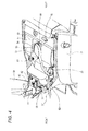
- a plug 55 which is a charge plug provided on a charge cord 57 which extends from a charger 58 (described later), is connected to the receptacle 53, whereby the battery 6 is charged.
- the charge cord 57 is led out leftwards of the vehicle with the plug 55 connected to the receptacle 53.
- a cutout portion 63 is formed in a left front portion of an edge portion of the opening portion 30 of the accommodation space S1.
- the charge cord 57 is passed through the cutout portion 63 in the opening portion 30.
- the seat 29 can close the opening portion 30 in the accommodation space S1 with the charge cord 57 which connects the plug 55 with the charger 58 led into the interior of the accommodation space S1.
- Fig. 5 shows an external appearance of the receptacle 53, wherein (a) shows a state in which a connection port 54 is closed, and (b) shows a state in which the connection port 54 is opened.
- the receptacle 53 includes a housing 71 which is formed from a synthetic resin or the like.
- a connection port 54 is formed in the housing 71, and a connecting portion 76 of the plug 55, which will be described later, can be connected to or disconnected from the connection port 54.
- connection port 54 is formed into a thin-flat shape as a whole. Specifically, the connection port 54 has an opening in which a dimension in a horizontal direction D1 which is perpendicular to an inserting direction D0 of the plug 55 is larger than a dimension in a vertical direction D2 which is perpendicular to the inserting direction and the horizontal direction.
- the housing 71 has a plurality of male terminals 72 in an interior of an outer circumferential wall 73 which defines the connection port 54 (see Fig. 8 ).
- a flange portion 81 which projects to a circumference of the outer circumferential wall 73, is formed on the housing 71 of the receptacle 53.
- Mounting holes 82 are formed in both side portions of the flange portion 81.
- the housing 71 is fixed in place within the connection box 51 by screwing screw members (not shown) which are inserted through the mounting holes 82 into threaded holes (not shown) provided in a sheet metal member.
- the housing 71 has a pair of guide grooves 84 in a lower portion of the outer circumferential wall 73 which defines the connection port 54. These guide grooves 84 are formed on a left- and right-hand sides of the housing 71 of the receptacle 53 in relation to a widthwise direction. These guide grooves 84 are formed along the inserting direction of the plug 55. Additionally, the receptacle 53 has a lid 85 which can close the connection port 54.
- the lid 85 is formed from a synthetic resin or the like and has a thin-flat plate portion 86.
- the lid 85 has a circumferential wall 87 on a side of the thin-flat plate portion 86 which faces the connection port 54.
- the circumferential wall 87 extends along the outer circumferential wall 73 of the housing 71 of the receptacle 53 with the lid 85 closing the connection port 54 of the receptacle 53.
- a lower end portion of the lid 85 is coupled to a pivot shaft so as to be pivotable about the pivot shaft.
- the pivot shaft is provided at a position below the connection port 54 in the housing 71 of the receptacle 53 so as to extend along a longitudinal direction of the connection port 54. Then, by causing the lid 85 to pivot about the pivot shaft, the connection port 54 of the receptacle 53 is opened or closed by the lid 85.
- Fig. 6 shows an external appearance of the plug 55, wherein (a) shows an external appearance as seen from thereabove, and (b) shows an external appearance as seen from therebelow.
- the plug 55 includes a housing 75 which is formed from a synthetic resin or the like.
- the connecting portion 76 is provided on this housing 75 so as to be inserted into the connection port 54 of the receptacle 53.
- the connecting portion 76 has a plurality of terminal accommodation portions 70 (see Fig. 8 ).
- the connecting portion 76 of the plug 55 is also formed into a thin-flat portion. Namely, the connecting portion 76 is formed so that a dimension in a first direction D1 which is perpendicular to the inserting direction D0 of the plug 55 is larger than a dimension in a second direction D2 which is perpendicular to the plug inserting direction and the first direction.
- the individual male terminals 72 are connected to corresponding female terminals 78 by inserting the connecting portion 76 of the plug 55 into the connection port 54 of the receptacle 53.
- the housing 75 of the plug 55 has a grip portion 101.
- the connecting portion 76 is provided at a front end portion of the grip portion 101.
- the grip portion 101 has a longer circumferential length that of the connecting portion 76.
- a rear end face 101 a of the grip portion 101 is inclined rearwards so as to gradually move away from the connecting portion 76 as it extends from a right end thereof to a left end thereof, and the left end of the rear end face 101 a is disposed rearwards than the right end thereof. Consequently, the grip portion 101 has an asymmetrical shape relative to the left-to-right direction, which is a shape which facilitates the gripping of the plug 55 by the right hand of the operator.
- a pair of elongated guide projections 104 are formed on a back face of the plug 55.
- the elongated guide projections 104 are formed over an overall length of the connecting portion 76 which includes part of the grip portion 101.
- the elongated guide projections 104 are formed on a left end and a right end of the plug 55 which correspond to a widthwise direction thereof.
- the elongated guide projections 104 are formed along the inserting direction in relation to the receptacle 53.
- the elongated guide projections 104 are slightly swollen at ends facing the grip portion 101.
- the two-wheeled electric vehicle 1 includes a BMS (Battery Management System) 103.
- BMS Battery Management System
- the BMS 103 is connected with the battery 6 via an electric power supply line 105 and a communication line 111 and serves as an electrical communication controller which controls an electrical communication with the battery 6.
- the BMS 103 and the receptacle 53 are connected together by a communication line 113.
- the seat open/close switch 42 which is operated by opening or closing the seat 29, is provided in a halfway position along the communication line 113.
- the seat open/close switch 42 is brought to the turn-off state when the seat 29 opens the opening portion 30 of the accommodation space S1 and is brought to the turn-on state when the seat 29 closes the opening portion 30.
- a signal carried by the communication line 113 is interrupted. This disables the communication between the receptacle 53 and the BMS 103.
- the seat open/close switch 42 is brought to the turn-on state, the transmission and reception of a signal through the communication line 113 is enabled. This enables a communication between the receptacle 53 and the BMS 103.
- the seat open/close switch 42 serves as a signal changer of the invention and changes the state of a signal carried by the communication line 113 based on whether the seat 29 is opened or closed.
- the charge cord 57 connected to the plug 55 has an electric power supply line 115, a communication line 116 and a connection detection line 117.
- the charge cord 57 is connected to the charger 58.
- a power supply cable 61 is connected to the charger 58.
- a plug 60 which can be connected to a power supply 62 (described later), is provided at an end portion of the power supply cable 61.
- the electric power supply lines 106, 115 are electrically connected with each other, whereby a charge path from the charger 58 to the battery 6 is formed.
- the communication lines 113, 116 are electrically connected with each other, whereby a communication path between the charger 58 and the BMS 103 is formed.
- a connection detection line 114 is electrically connected with the connection detection line 117, whereby a circuitry is formed which can detect a connection of the plug 55 to the receptacle 53.
- the BMS 103 detects that the plug 55 is connected to the receptacle 53 by monitoring the voltage of the connection detection line 114.
- the BMS 103 When a communication with the charger 58 is established, the BMS 103 establishes an electrical communication between the receptacle 53 and the battery 6. Namely, the BMS 103 continues to interrupt the electrical communication between the battery 6 and the receptacle 53 as long as a communication cannot be established between the charger 58 and itself.
- Fig. 8 shows schematically a wiring between the two-wheeled electric vehicle 1 and the charger 58.
- the receptacle 53 is connected to the battery 6 via a wiring 56. Additionally, the plug 55 which is connected to the receptacle 53 is connected to the charge cord 57. The charge cord 57 is connected to the charger 58.
- the power supply 62 is connected to the charger 58 via an electric wire 61. With this configuration, with the plug 55 connected to the receptacle 53, electric power from the power supply 62 is supplied to the battery 6 via the charger 58, whereby the battery 6 is charged.
- the plurality of male terminals 72 which are provided in the receptacle 53 are supported in the housing 71 so as to extend from a proximal portion 71 a of the housing 71 towards the connection port 54. These male terminals 72 are arrayed in a longitudinal direction (the first direction) of the thin-flat shape of the housing 71. Bulkhead portions 74 are formed in the housing 71 so as to insulate the male terminals 72 individually.
- the male terminals 72 include a positive terminal 72a, a first communication terminal 72b, a second communication terminal 72c, a connection detection terminal 72d, a ground terminal 72e, and a negative terminal 72f, which are disposed sequentially in that order from one end side of the housing 71 in the longitudinal direction thereof. Then, the first communication terminal 72b and the second communication terminal 72c, the connection detection terminal 72d, and the ground terminal 72e are disposed between the positive terminal 72a and the negative terminal 72f.
- the positive terminal 72a and the negative terminal 72f are connected to a power supply line 106 of the battery 6 which is installed in the two-wheeled electric vehicle 1.
- the first communication terminal 72b and the second communication terminal 72c are connected to the communication line 113 which is used for signal transmission between the BMS 103 the charger 58.
- the BMS 103 is installed in the two-wheeled electric vehicle 1 as a control unit.
- the connection detection terminal 72d is connected to the connection detection line 114 which is used for detection of the insertion of the plug 55 into the connection port 54.
- the ground terminal 72e is connected to a ground line 121 of the two-wheeled electric vehicle 1.
- the plurality of terminal accommodation portions 70 in the connecting portion 76 are arrayed in the longitudinal direction (that is, the first direction D1) of the thin-flat-shaped housing 75. Slits 77 are formed individually between the terminal accommodation portions 70 so that the bulkhead portions 74 which are formed in the housing 71 of the receptacle 53 can be inserted thereinto.
- the female terminals 78 are accommodated individually in the terminal accommodation portions 70. Namely, the plurality of female terminals 78 are arrayed in the longitudinal direction of the thin-flat shape in an interior of the connecting portion 76.
- the female terminals 78 include a positive terminal 78a, a first communication terminal 78b, a second communication terminal 78c, a connection detection terminal 78d, a ground terminal 78e, and a negative terminal 78f which are disposed sequentially in that order from one end side of the housing 75 in the longitudinal direction thereof. Then, the first communication terminal 78b, the second communication terminal 78c, the connection detection terminal 78d, and the ground terminal 78e are disposed between the positive terminal 78a and the negative terminal 78f.
- the positive terminal 78a and the negative terminal 78f are connected to the power supply line 115 of the charger 58.
- the first communication terminal 78b and the second communication terminal 78c are connected to the communication line 116 which is used for signal transmission between the BMS 103 and the charger 58.
- the BMS 103 is the control unit installed in the two-wheeled electric vehicle 1.
- the connection detection terminal 78d is connected to the connection detection line 117 which is used for detection of the insertion of the plug 55 into the connection port 54.
- the ground terminal 78e is connected to a ground line 122 of the charger 58.
- the seat 29 of the two-wheeled electric vehicle 1 is opened to reveal the accommodation space S1. Accordingly, as shown at (a) in Fig. 9 , the button portion 43 of the seat open/close switch 42 which has been depressed by the rib 41 on the seat 29 projects outwards, whereby the seat open/close switch 42 is brought to the turn-off state. This disables the communication between the receptacle 53 and the BMS 103 via the communication line 113.
- the operator who grips the plug 55 guides the plug 55 into the accommodation space S1, opens the lid 85 to reveal the connection port 54 of the receptacle 53 and inserts the connecting portion 76 of the plug 55 into the connection port 54. Then, the elongated guide projections 104 on the back face of the plug 55 are fitted in the guide grooves 84 of the housing 71 of the receptacle 53.
- the electric power supply line 106 on the side of the BMS 103 and the electric power supply line 115 on the side of the charger 58 are connected together, and the communication line 113 on the side of the BMS 103 and the communication line 116 on the side of the charger 58 are connected together.
- the connection detection line 114 on the side of the BMS 103 and the connection detection line 117 on the side of the charger 58 are connected together, whereby the BMS 103 detects that the plug 55 is connected to the receptacle 53.
- the charge cord 57 is disposed in the cutout portion 63 formed in the opening portion 30 of the accommodation space S1 as shown in Fig. 4 , and the seat 29 is closed to cover the opening portion 30 of the accommodation space S1. Accordingly, as shown at (b) in Fig. 9 , the button portion 43 of the seat open/close switch 42 is depressed by the rib 41 on the seat 29 to bring the seat open/close switch 42 to the turn-on state.
- the plurality of female terminals 78 are arrayed along the longitudinal direction of the thin-flat connecting portion 76. Further, the positive terminal 78a and the negative terminal 78f are spaced sufficiently apart from each other by the other female terminals 78 which are disposed therebetween. Consequently, heat generated at the positive terminal 78a and the negative terminal 78f can be dissipated well at both end portions of the housing 75. Therefore, the influence of heat generated during charging can be reduced as much as possible.
- the seat 29 is opened to reveal the accommodation space S1. Accordingly, as shown at (a) in Fig. 9 , the button portion 43 of the seat open/close switch 42 which has been depressed by the rib 41 on the seat 29 projects outwards, whereby the seat open/close switch 42 is brought to the turn-off state.
- This disables the communication between the BMS 103 and the charger 58. Accordingly, the BMS 103 determines that the communication with the charger 58 is disabled, and interrupts the electrical communication between the receptor 53 and the battery 6.
- the plug 55 is disconnected from the receptacle 53, so that the electrically communicating state between the male terminals 72 of the receptacle 53 and the female terminals 78 of the plug 55 is released. Accordingly, the electric power supply line 106 on the side of the BMS 103 and the electric power supply line 115 on the side of the charger 58 are disconnected, and the communication line 113 on the side of the BMS 103 and the communication line 116 on the side of the charger 58 are disconnected. Additionally, when the plug 55 is disconnected from the receptacle 53, the BMS 103 detects, based on the voltage of the connection detection line 114, that the plug 55 has been disconnected from the receptacle 53.
- connection port 54 of the receptacle 53 is closed by the lid 85. Thereafter, the plug 55 is removed from the accommodation space S1, and the seat 29 is closed to cover the opening portion 30 of the accommodation space S1. Since rainwater or dust is prevented from intruding into the accommodation space S1 as a result of the accommodation space S1 being closed by the seat 29, the receptacle 53 is protected twofold by the seat 29 and the lid 85.
- the seat open/close switch 42 changes the signaling state of the communication line 113 based on whether the seat 29 is opened or closed to interrupt or connect the communication path between the receptacle 53 and the BMS 103. Then, in the event that the BMS 103 recognizes through the signaling state of the communication line 113 that the seat 29 does not close the opening portion 30 of the accommodation space S1, even with the plug 55 inserted in the receptacle 53, the BMS 103 interrupts the electrical communication between the receptacle 53 and the battery 6. Accordingly, the generation of arc discharge can be reliably prevented when the plug 55 is connected to or disconnected from the receptacle 53 with the seat 29 opened.
- the switching operation which triggers the interrupting of an electric communication is executed by the seat open/close switch 42 which is disposed in a position which lies far away from the area where the plug 55 is connected to or disconnected from the receptacle 53. Because of this, the electrical communication interrupting operation and the connecting/disconnecting operation of the plug 55 can be separated, thereby making it possible to prevent the generation of arc discharge more reliably.
- the function to interrupt the electrical communication to prevent arc discharge does not have to be incorporated in the receptacle 53 or the plug 55, it is possible to realize a reduction in size of the receptacle 53 and the plug 55 while preventing the generation of arc discharge.
- the straddle-type vehicle such as a two-wheeled vehicle where the parts installation space is limited compared with a four-wheeled vehicle, it is possible to enhance the degree of freedom in disposing the receptacle 53.
- the receptacle 53 Due to the receptacle 53 being reduced in size, it is possible to dispose the receptacle 53 in the accommodation space S1 under the seat 29 which is the existing equipment. Consequently, it is possible to obviate the necessity of providing an exclusive accommodation space for the receptacle 53 and providing an electrical communication interrupting switch on a lid which opens or closes the accommodation space, thereby making it possible to realize a reduction in size and cost of the vehicle itself.
- the small plug 55 can be used, it is possible to keep the seat 29, which is the lid for the accommodation space S1, closed easily during charging. Consequently, the waterproofness of the location where the receptacle 53 and the plug 55 are connected together can be realized, and an intentional disconnection of the plug 55 during charging can be prevented.
- the seat open/close switch 42 has a fixed portion where the seat open/close switch 42 is fixed to the hinge portion 38 with a screw member 42a.
- the receptacle 53 also has a fixed portion where the receptacle 53 is fixed to the side wall 52 of the connection box 51 with screw members and mounting holes 82. Consequently, not only can the functions of the seat open/close switch 42 and the receptacle 53 be separated, but also the seat open/close switch 42 and the receptacle 53 can be disposed in positions which are suitable for their functions and positions where they are prevented from interfering with each other.
- the BMS 103 has fixed portions where the BMS 103 is fixed to a side of a frame main body 20 with screw members 103a. Consequently, not only can the functions of the BMS 103 and the open/close switch 42 be separated, but also the BMS 103 and the open/close switch 42 can be positioned in the positions suitable for their functions and in the positions where they do not interfere with each other. Consequently, it is possible to equip the small receptacle 53 which is suitable for the two-wheeled electric vehicle 1 whose parts installation space is limited compared with that of the four-wheeled vehicle. In addition to this, it is possible to reliably prevent the generation of arc discharge when the plug 55 is connected to or disconnected from the receptacle 53.
- the electrical communication control performed by the BMS 103 does not require that the electrical communication between the receptacle 53 and the battery 6 be interrupted completely.
- a configuration may be adopted in which the voltage or current at the receptacle 53 is reduced to such an extent that the generation of arc discharge is prevented which would occur in association with the connection or disconnection of the plug 55.
- a configuration may be adopted in which a receptacle 53 is disposed in an accommodation space S2 which is provided on a left side of the vehicle in a rear cover 27.
- An opening portion 212 of this accommodation space S2 is opened sideward of the vehicle.
- a lid member 213 configured to open or close the opening portion 212 is provided on an outer wall of the accommodation space S2.
- the lid member 213 is opened to reveal the opening portion 212 of the accommodation space S2. Thereafter, as has been described before, the plug 55 is inserted into the connection port 54 of the receptacle 53 , and the battery 6 is charged with a claw portion 88 of the lid 85 preventing the dislocation of the plug 55 and the opening portion 212 closed by the lid member 213.
- a lid member open/close switch 214 which is operated when the lid member 213 is opened or closed is provided on the communication line 113 which connects the receptacle 53 with the BMS 103. Similarly to the embodiment described above, whether the plug 55 is connected to or disconnected from the receptacle 53, the lid open/close switch 214 changes the signaling state of the communication line 113 based on whether the lid member 213 is opened or closed to thereby interrupt or connect the communication path between the receptacle 53 and the BMS 103.
- the BMS 103 interrupts the electrical communication between the receptacle 53 and the battery 6 even with the plug 55 inserted in the receptacle 53.
- the function as the electrical communication control unit which controls the electrical communication between the receptacle 53 and the battery 6 does not necessarily have to be realized only by the BMS 103 alone. At least part of the function as the electrical communication control unit is allowed to be realized by at least either of a CCU (Cell Control Unit) and an MCU (Machine Control Unit) which are installed in the two-wheeled electric vehicle 1 so as to have a control function.
- a CCU Cell Control Unit
- MCU Machine Control Unit
- the position of the seat open/close switch 42 which is operated when opening or closing the seat 29 which is the lid member is not limited to that described in the embodiment.
- An appropriate position can be selected as the position where to dispose the seat open/close switch 42, as long as the position is spaced away from the area where the plug 55 is connected to or disconnected from the receptacle 53. This will be true with the lid open/close switch 214 of the two-wheeled electric vehicle 1A.
- the combination of the on/off state of the seat open/close switch 42 and the interrupted state of the communication line 113 is arbitrary. Namely, a configuration may be adopted in which a signal carried by the communication line 113 is interrupted when the seat open/close switch 42 is brought to the turn-on state. This will be true with the lid open/close switch 214.
- the combination of the open/closed state of the seat 29 and the interrupted state of the communication line 113 is also arbitrary. Namely, a configuration may be adopted in which a signal is allowed to be carried by the communication line 113 in such a state that the seat 29 opens the opening portion 30 of the accommodation space S1, and the BMS 103 interrupts the electrical communication between the receptacle 53 and the battery 6 based on the fact that the signal is carried by the signal line 113. This will be true with the lid open/close switch 214.
- the communication line 113 does not necessarily have to be interrupted directly by the seat open/close switch 42.
- a configuration may be adopted in which the communication line 113 is interrupted by an appropriate circuitry element which is operated by a signal outputted from the seat open/close switch 42.
- the function as the signal changer which changes the signaling state of the signal line 113 based on whether the seat 29 is opened or closed can also be realized by a position sensor which changes the signal according to whether the seat 29 is opened or closed. This will be true with the lid open/close switch 214.
- the signal line whose signaling state is changed based on whether the seat 29 is opened or closed is not limited to the communication line 113. From the viewpoint of preventing arc discharge, any signal line other than the power supply line may suffice, and a configuration may be adopted in which the seat open/close switch 42 is provided in a halfway position along the length of the connection detection line 114.
- the number of wheels of the straddle-type electric vehicle to which the invention is applied is not limited to two and hence can be determined as required.
Landscapes
- Engineering & Computer Science (AREA)
- Mechanical Engineering (AREA)
- Power Engineering (AREA)
- Transportation (AREA)
- Life Sciences & Earth Sciences (AREA)
- Sustainable Development (AREA)
- Sustainable Energy (AREA)
- Electric Propulsion And Braking For Vehicles (AREA)
- Arrangement Or Mounting Of Propulsion Units For Vehicles (AREA)
Abstract
Description
- The present invention relates to a straddle-type electric vehicle.
- An electric vehicle provided with an electric motor as a power supply source includes a charging receptacle for charging a battery. When charging the battery, a plug provided at an end portion of a cord extending from a charger is connected to the receptacle.
- As a connector used in charging the electric vehicle, there is known a connector which includes a lock mechanism, a locking operation detector, and a lock controller (for example, see Patent Document 1). In this connector, the lock mechanism locks and unlocks a charger-side connector and a vehicle-side connector into and from a coupled state, and the locking operation detector detects an operating state of the lock mechanism. Then, the lock controller switches a control switch which opens or closes a charge line from a charging power supply to the battery between an open state and a closed state based on the result of the detection made by the locking operation detector.
- In this connector, when the locking operation detector detects that the lock mechanism has been put in a locking state with the vehicle-side connector coupled to the charger-side connector, the control switch provided on the charge line is put in the closed state. Then, electric power is supplied from the charging power supply to the battery via the charge line, whereby an electrical communication is established between the connectors. Here, when a person who does not know that charging is being performed attempts to disconnect the connectors, although the connectors are electrically communicating with each other, the locking operation detector detects that the lock mechanism has been put in an unlocking state. Then, the control switch is put in the open state, whereby the electrical communication between the connectors is interrupted. This can prevent the generation of arc discharge that would occur between contacts of the connectors when the connectors are disconnected, whereby the protection of the contacts is ensured.
- [Patent Document 1] Japanese Patent Publication No.
10-262340A - In the configuration described above, however, with a view to preventing the arc discharge by switching the control switch provided on the charge line, an electrical communication interrupting mechanism including the lock mechanism, the locking operation detector and the lock controller is incorporated in a main body of the plug (the charge connector). This calls for the enlargement of the plug. Consequently, it cannot be avoided that the receptacle (the vehicle-side connector) to which the plug which is so enlarged is connected is also enlarged.
- A parts installation space is limited on a straddle-type vehicle such as a two-wheeled electric vehicle, compared with a four-wheeled vehicle. This requires that the receptacle is also disposed within the narrow space. Consequently, it is difficult to install a large respectable which is large enough to permit the connection of a large plug like the one described above in a straddle-type electric vehicle.
- Consequently, an object of the invention is to provide a straddle-type electric vehicle which enables the installation of a small receptacle and which can ensure the prevention of the generation of arc discharge when a plug is connected to or disconnected from the receptacle.
- In order to achieve the above object, according to one aspect of the present invention there is provided a straddle-type electric vehicle, comprising:
- a charge receptacle to which a charge plug is removably connected;
- an accommodation portion having an opening portion and provided with a charge receptacle;
- a lid configured to open or close the opening portion of the accommodation portion;
- a battery connected to the charge receptacle so as to be able to establish electrical communication therewith;
- an electrical communication controller configured to control the electrical communication between the charge receptacle and the battery;
- a signal line connected to the electrical communication controller; and
- a signal changer configured to change a state of a signal carried by the signal line,
- wherein the lid forms a part of an outer face of a vehicle body;
- wherein the lid is configured to be able to close the opening portion under a condition that the charge plug is connected to the charge receptacle;
- wherein the signal changer is configured to change the state of the signal based on a state of the lid opening or closing the opening portion, irrespective of whether the charge plug is connected to the charge receptacle or not; and
- wherein the electrical communication controller is configured to interrupt or limit the electrical communication between the charge receptacle and the battery based on the state of the signal, in a case where the opening portion is unclosed by the lid even if the charge plug is connected to the charge receptacle.
- In the above configuration, the lid, which is configured to open or close the opening portion of the accommodation portion provided with the charge receptacle, forms the outer face of the vehicle body. In addition, the lid is configured to be able to close the opening portion under a condition that the charge plug is connected to the charger receptacle. With this configuration, the lid is necessarily operated to open or close the opening portion when charging is performed. The state of the signal is then changed based on the state of the lid opening or closing the opening portion, irrespective of whether the charge plug is connected to the charge receptacle or not. In a case where the opening portion is unclosed by the lid even if the charge plug is connected to the charge receptacle, the electrical communication between the charge receptacle and the battery is interrupted or limited. Accordingly, it is possible to reliably prevent the generation of arc discharge without providing equipment for preventing the arc discharge on the charge plug or the charge receptacle. Consequently, it is possible to provide a downsized charge receptacle which is suitable for the straddle-type vehicle such as the two-wheeled electric vehicle wherein the parts installation space is limited compared with the four-wheeled vehicle. Moreover, it is possible to reliably prevent the generation of arc discharge when the plug is connected to or disconnected from such a charge receptacle.
- Each of the signal changer and the charge receptacle is provided with a fixed portion configured to be fixed on the vehicle body. With this configuration, not only can the functions of the respective members be separated, but also the respective members can be disposed in positions which are suitable for their functions and positions where they are prevented from interfering with each other. Consequently, it is possible to provide a downsized charge receptacle which is suitable for the straddle-type vehicle such as the two-wheeled electric vehicle wherein the parts installation space is limited compared with the four-wheeled vehicle. Moreover, it is possible to reliably prevent the generation of arc discharge when the plug is connected to or disconnected from such a charge receptacle.
- Each of the signal changer and the electrical communication controller is provided with a fixed portion configured to be fixed on the vehicle body. With this configuration, not only can the functions of the respective members be separated, but also the respective members can be disposed in positions which are suitable for their functions and positions where they are prevented from interfering with each other. Consequently, it is possible to provide a downsized charge receptacle which is suitable for the straddle-type vehicle such as the two-wheeled electric vehicle wherein the parts installation space is limited compared with the four-wheeled vehicle. Moreover, it is possible to reliably prevent the generation of arc discharge when the plug is connected to or disconnected from such a charge receptacle.
- The signal changer may be a switch configured to interrupt the signal carried by the signal line when the opening portion is unclosed by the lid, or may be a switch configured to interrupt the signal carried by the signal line when the opening portion is closed by the lid. Alternatively, the signal changer is a position sensor configured to change the signal in accordance with a position of the lid opening or closing the opening portion.
- In a case where the signal line is a communication line connecting the electrical communication controller and a control unit of a charger configured to supply power to the battery, it is not necessary to provide an individual signal line for controlling the interruption of charging. Consequently, the increase of the number of terminals in the charge receptacle can be avoided, whereby contributing to the cost reduction and the improvement of the connection reliability.
- In a case where the lid is a part of a seat on which a rider can get seated, it is possible to dispose the charge receptacle in the accommodation space under the seat which is the existing equipment.
- The charge receptacle may be configured such that: a dimension in a first direction, which is perpendicular to a connecting-disconnecting direction of the charger plug, is larger than a dimension in a second direction, which is perpendicular to the first direction and the connecting-disconnecting direction; and a plurality of terminals are arrayed in the first direction. In this case, a connection port of the charge receptacle can be formed into a thin-flat shape. Consequently, it is possible to enhance the degree of freedom in disposing the charge receptacle even in the straddle-type vehicle where the parts installation space is relatively limited. Moreover, it is possible to arrange power supply terminals, which likely generate heat, apart from each other.
-
-
Fig. 1 is a left side view showing a two-wheeled electric vehicle according to an embodiment of the invention. -
Fig. 2 is a left side view of the two-wheeled electric vehicle shown inFig. 1 with some of constituent components removed therefrom. -
Fig. 3 is a perspective view showing an accommodation space in a state that a seat of the two-wheeled electric vehicle shown inFig. 1 is opened. -
Fig. 4 is a perspective showing a state that a plug is connected to a receptacle provided in the accommodation space shown inFig. 3 . -
Fig. 5 is a perspective view showing the appearance of the receptacle shown inFig. 4 . -
Fig. 6 is a perspective view showing the appearance of the plug shown inFig. 4 . -
Fig. 7 is a diagram showing a configuration of a charge system in the two-wheeled vehicle shown inFig. 1 . -
Fig. 8 is a view schematically showing wirings between a charger and the two-wheeled vehicle shown inFig. 1 . -
Fig. 9 is a right side view showing a relationship between an open/close state of the sheet of the two-wheeled vehicle shown inFig. 1 and a sheet open/close switch. -
Fig. 10 is a left side view showing a variation example of the two-wheeled vehicle shown inFig. 1 wherein a location of the receptacle is different. - Referring to the accompanying drawings, the invention will be described in detail below. In the individual drawings for use in the following description, the scales are changed as required so that individual constituent members are illustrated in good sizes for recognition.
-
Fig. 1 is a left side view showing a two-wheeled electric vehicle according to an embodiment of the invention. In this embodiment, a two-wheeledelectric vehicle 1 which takes the form of a scooter will be described as a straddle-type electric vehicle. The two-wheeledelectric vehicle 1 can run with luggage placed at a front portion and a rear portion thereof and is suitable for application to a luggage carrying vehicle. - Directions denoted as front and rear, top and bottom, as well as left and right are based on a standard posture of the two-wheeled
electric vehicle 1 which corresponds to a state in which the two-wheeledelectric vehicle 1 runs straight ahead on a horizontal plane and the point of view of a rider when the rider faces the front of the vehicle. In addition, the configuration of the two-wheeledelectric vehicle 1 will be described based on the two-wheeledelectric vehicle 1 in such a state that the vehicle stands erect, afront wheel 3 and a rear wheel 4 are in contact with a road face A1, and the vehicle is in an unloaded state without a rider. - The two-wheeled
electric vehicle 1 comprises abody frame 2, thefront wheel 3, the rear wheel 4, anelectric motor 5, abattery 6, and abody cover 7. In the two-wheeledelectric vehicle 1, theelectric motor 5 is driven by electric power supplied from thebattery 6, and the rear wheel 4 is driven by the output of theelectric motor 5. Theelectric motor 5 is accommodated in apower unit 47 which is disposed in the rightward of the rear wheel 4. Hereinafter, an overall construction of the two-wheeledelectric vehicle 1 will be described sequentially from the front of a vehicle body. -
Fig. 2 is a left side view of the two-wheeled electric vehicle shown inFig. 1 with some of constituent components removed therefrom. The two-wheeledelectric vehicle 1 has a head pipe 8 which is disposed at a front upper portion of the two-wheeledelectric vehicle 1. A steeringshaft 9 is inserted rotatably in the head pipe 8. Afront fork 10 having a pair of left and right fork legs is mounted at a lower end portion of thesteering shaft 9. Thefront wheel 3 is attached to thefront fork 10. - A
handlebar 11 is mounted at an upper end portion of thesteering shaft 9. The rider controls thehandlebar 11 so as to turn thesteering shaft 9, thefront fork 10 and thefront wheel 3 around an axis of thesteering shaft 9. -
Grips 12 are provided individually at both left and right end portions of the handlebar 11 (only a left grip is shown). A right grip constitutes a throttle grip. The rider turns the throttle grip so as to control the output of theelectric motor 5. - As shown in
Fig. 1 , ameter 13 is provided in the vicinity of a center of thehandlebar 11. Aluggage rack 14 is disposed below themeter 13. Theluggage rack 14 is fixed to the head pipe 8. The load of luggage placed on theluggage rack 14 acts mainly on thefront wheel 3 via the head pipe 8 and thesteering shaft 9. Aheadlamp 15 is fixed to a lower portion of theluggage rack 14. - As shown in
Fig. 2 , the two-wheeledelectric vehicle 1 comprises abody frame 2 which extends rearwards from the head pipe 8. Thebody frame 2 is formed by using a steel pipe member or the like. Thebody frame 2 comprises adown tube 19 and a framemain body 20 which is disposed in rearward of thedown tube 19. The downtube 19 extends obliquely downwards and rearwards from a lower portion of the head pipe 8. When seen from the side, the framemain body 20 extends rearwards from a lower end portion of thedown tube 19, and a halfway portion of the framemain body 20 in relation to a front-to-rear direction X1 of the vehicle is formed into an S shape. - The frame
main body 20 includes a pair of left and right frame main bodies. The framemain body 20 includes afirst frame portion 21, asecond frame portion 22, athird frame portion 23, and afourth frame portion 24. Thefirst frame portion 21 extends substantially straight and rearwards from the lower end portion of thedown tube 19 and is slightly inclined obliquely upwards and rearwards. - The
second frame portion 22 is formed into an S shape when seen from the side. Thesecond frame portion 22 includes alower end portion 22a, amiddle portion 22b, and anupper end portion 22c. Thelower end portion 22a of thesecond frame portion 22 is formed into a curved shape and is connected to a rear end portion of thefirst frame portion 21. Themiddle portion 22b of thesecond frame portion 22 extends obliquely upwards rearwards from thelower end portion 22a. When seen from the side, an inclination angle of themiddle portion 22b in relation to thefirst frame portion 21 is, for example, 45 degrees or thereabout. Theupper end portion 22c of thesecond frame portion 22 is formed into a curved shape and is connected to themiddle portion 22b. - The
third frame portion 23 extends rectilinearly from theupper end portion 22c and is slightly inclined obliquely upwards and rearwards. Thefourth frame portion 24 extends rearwards from themiddle portion 22b of thesecond frame portion 22, is curved obliquely upwards in a halfway position and is connected to a middle portion of thethird frame portion 23. - As shown in
Fig. 1 , the two-wheeledelectric vehicle 1 comprises thebody cover 7 which is attached to thebody frame 2. Thebody cover 7 comprises afront cover 25 which covers the head pipe 8, alower cover 26 which extends downwards from a lower portion of thefront cover 25, and arear cover 27 which is disposed in rearward of thefront cover 25. - The
front cover 25 surrounds part of thesteering shaft 9 and the head pipe 8 and also surrounds thedown tube 19. Thelower cover 26 extends rearwards from alower portion 25a of thefront cover 25 and covers thefirst frame portions 21 and thelower end portions 22a of thesecond frame portions 22 from the below, the left, and the right thereof. Afoot rest portion 28 is disposed at an upper end portion of thelower cover 26. Thefoot rest portion 28 is provided so that the rider rests his or her feet thereon and is made substantially thin-flat. - The
rear cover 27 is shaped, as a whole, so as to extend obliquely upwards and rearwards from arear portion 26a of thelower cover 26. Therear cover 27 covers areas of thesecond frame portions 22 excluding thelower end portions 22a from the front, the left, and the right thereof. Additionally, therear cover 27 covers thethird frame portions 23 and thefourth frame portions 24 from the front, the left, and the right thereof. - A
seat 29 is disposed above therear cover 27. The feet of the rider sitting on theseat 29 rest on thefoot rest portion 28 while the two-wheeledelectric vehicle 1 is running. In the front-to-rear direction X1, thefoot rest portion 28 is disposed between a rear face 25b of thefront cover 25 and afront end portion 29a of theseat 29. Additionally, theseat 29 is disposed above thesecond frame portions 22, part of thethird frame portions 23, and part of thefourth frame portions 24. A space surrounded by theseat 29 and therear cover 27 defines an accommodation space S1. - As shown in
Fig. 2 , theseat 29, which serves as a lid of the invention, is supported by afirst bracket 31 and asupport bracket 37, constituting part of an external face of the vehicle body. Thefirst bracket 31 is mounted at themiddle portions 22b of thesecond frame portions 22. Thefirst bracket 31 extends upwards from themiddle portions 22b. Ahinge portion 38 is provided at an upper end portion of thefirst bracket 31. Theseat 29 is supported by thefirst bracket 31 via thehinge portion 38. Thefirst bracket 31 supports theseat 29 from the below thereof. Theseat 29 can pivot about thehinge portion 38. The accommodation space S1 can be opened upwards by causing theseat 29 to pivot about thehinge portion 38. It is noted that thehinge portion 38 may be omitted so that theseat 29 is fixed directly to thefirst bracket 31. - A rear portion 29b of the
seat 29 is supported by thesupport bracket 37. Thesupport bracket 37 is fixed to thethird frame portions 23 of thebody frame 2 and is shaped so as to project upwards from thethird frame portions 23. - The
battery 6, which is a power supply for theelectric motor 5, is disposed below theseat 29. Thebattery 6 is disposed between the pair of left and rightsecond frame portions 22. Thebattery 6 is a rechargeable secondary battery. When seen from the side, thebattery 6 has a substantially rectangular shape in which a length (a height) in a vertical direction Z1 of the vehicle is longer than a length (a width) in the front-to-rear direction X1. Thebattery 6 is disposed in a posture in which thebattery 6 is inclined obliquely rearwards with its front lying higher than its rear and is supported on thebody frame 2. An upper portion 6a of thebattery 6 is disposed between thefirst bracket 31 and thesupport bracket 37. - As shown in
Fig. 1 , aluggage rack 45 is disposed at the rear of theseat 29. Theluggage rack 45 is disposed on thethird frame portions 23 to be supported by thethird frame portions 23. Luggage can be placed on theluggage rack 45. The load of the luggage placed on theluggage rack 45 is borne mainly by the rear wheel 4. - In this way, the
luggage rack 14, thebattery 6 which is heavy, and theluggage rack 45 are disposed so as to be aligned in the front-to-rear direction X1. Consequently, when luggage is placed on theluggage rack 14 and theluggage rack 45, the load of the two-wheeledelectric vehicle 1 can be balanced evenly in the front-to-rear direction X1. Consequently, even with the luggage placed on theluggage rack 14 and theluggage rack 45, it is possible to maintain the high controllability of the two-wheeledelectric vehicle 1. -
Fig. 3 is a perspective view showing an accommodation space S1 with aseat 29 opened. By causing theseat 29 to pivot upwards about ahinge portion 38, an openingportion 30 is revealed so that the accommodation space S1 is opened upwards. In addition, by causing theseat 29 to pivot about thehinge portion 38 in a reverse direction to the direction in which theseat 29 is opened to be closed, the openingportion 30 is closed. In this way, theseat 29 serves as a lid member which can close the accommodation space S1. Rainwater or dust is prevented from intruding into an interior of the accommodation space S1 as a result of theseat 29 closing the openingportion 30. - As shown in
Fig. 4 , arib 41 is formed on a back face of theseat 29 near a connecting portion with thehinge portion 38 which supports theseat 29 pivotably relative to thefirst bracket 31. Thisrib 41 is disposed on an upper portion of thehinge portion 38 when theseat 29 is closed. - A seat open/close switch (a switch) 42 is provided at the
hinge portion 38. This seat open/close switch 42 has abutton portion 43. Thisbutton portion 43 is pushed out towards theseat 29 by means of a spring incorporated therein. In this seat open/close switch 42, when theseat 29 is closed, thebutton portion 43 is depressed by therib 41 on theseat 29. The seat open/close switch 42 is brought to a turn-on state when thebutton portion 43 is depressed and brought to a turn-off state when thebutton portion 43 is released to project. - A
connection box 51 is provided in an area closer to a right end of the accommodation space S1. Areceptacle 53, which serves as a charge receptacle of the invention, is provided in aleft side wall 52 of theconnection box 51. Thereceptacle 53 is connected to abattery 6 so as to electrically communicate therewith. As shown inFig. 4 , aplug 55, which is a charge plug provided on acharge cord 57 which extends from a charger 58 (described later), is connected to thereceptacle 53, whereby thebattery 6 is charged. - The
charge cord 57 is led out leftwards of the vehicle with theplug 55 connected to thereceptacle 53. Acutout portion 63 is formed in a left front portion of an edge portion of the openingportion 30 of the accommodation space S1. Thecharge cord 57 is passed through thecutout portion 63 in the openingportion 30. With this configuration, theseat 29 can close the openingportion 30 in the accommodation space S1 with thecharge cord 57 which connects theplug 55 with thecharger 58 led into the interior of the accommodation space S1. -
Fig. 5 shows an external appearance of thereceptacle 53, wherein (a) shows a state in which aconnection port 54 is closed, and (b) shows a state in which theconnection port 54 is opened. Thereceptacle 53 includes ahousing 71 which is formed from a synthetic resin or the like. Aconnection port 54 is formed in thehousing 71, and a connectingportion 76 of theplug 55, which will be described later, can be connected to or disconnected from theconnection port 54. - The
connection port 54 is formed into a thin-flat shape as a whole. Specifically, theconnection port 54 has an opening in which a dimension in a horizontal direction D1 which is perpendicular to an inserting direction D0 of theplug 55 is larger than a dimension in a vertical direction D2 which is perpendicular to the inserting direction and the horizontal direction. Thehousing 71 has a plurality ofmale terminals 72 in an interior of an outercircumferential wall 73 which defines the connection port 54 (seeFig. 8 ). - A
flange portion 81, which projects to a circumference of the outercircumferential wall 73, is formed on thehousing 71 of thereceptacle 53. Mountingholes 82 are formed in both side portions of theflange portion 81. Thehousing 71 is fixed in place within theconnection box 51 by screwing screw members (not shown) which are inserted through the mountingholes 82 into threaded holes (not shown) provided in a sheet metal member. - The
housing 71 has a pair ofguide grooves 84 in a lower portion of the outercircumferential wall 73 which defines theconnection port 54. These guidegrooves 84 are formed on a left- and right-hand sides of thehousing 71 of thereceptacle 53 in relation to a widthwise direction. These guidegrooves 84 are formed along the inserting direction of theplug 55. Additionally, thereceptacle 53 has alid 85 which can close theconnection port 54. - The
lid 85 is formed from a synthetic resin or the like and has a thin-flat plate portion 86. Thelid 85 has acircumferential wall 87 on a side of the thin-flat plate portion 86 which faces theconnection port 54. Thecircumferential wall 87 extends along the outercircumferential wall 73 of thehousing 71 of thereceptacle 53 with thelid 85 closing theconnection port 54 of thereceptacle 53. - A lower end portion of the
lid 85 is coupled to a pivot shaft so as to be pivotable about the pivot shaft. The pivot shaft is provided at a position below theconnection port 54 in thehousing 71 of thereceptacle 53 so as to extend along a longitudinal direction of theconnection port 54. Then, by causing thelid 85 to pivot about the pivot shaft, theconnection port 54 of thereceptacle 53 is opened or closed by thelid 85. -
Fig. 6 shows an external appearance of theplug 55, wherein (a) shows an external appearance as seen from thereabove, and (b) shows an external appearance as seen from therebelow. Theplug 55 includes ahousing 75 which is formed from a synthetic resin or the like. The connectingportion 76 is provided on thishousing 75 so as to be inserted into theconnection port 54 of thereceptacle 53. The connectingportion 76 has a plurality of terminal accommodation portions 70 (seeFig. 8 ). - Similarly to the
connection port 54 of thereceptacle 53, the connectingportion 76 of theplug 55 is also formed into a thin-flat portion. Namely, the connectingportion 76 is formed so that a dimension in a first direction D1 which is perpendicular to the inserting direction D0 of theplug 55 is larger than a dimension in a second direction D2 which is perpendicular to the plug inserting direction and the first direction. - The individual
male terminals 72 are connected to correspondingfemale terminals 78 by inserting the connectingportion 76 of theplug 55 into theconnection port 54 of thereceptacle 53. - As shown at (a) in
Fig. 6 , thehousing 75 of theplug 55 has agrip portion 101. The connectingportion 76 is provided at a front end portion of thegrip portion 101. Thegrip portion 101 has a longer circumferential length that of the connectingportion 76. - A rear end face 101 a of the
grip portion 101 is inclined rearwards so as to gradually move away from the connectingportion 76 as it extends from a right end thereof to a left end thereof, and the left end of the rear end face 101 a is disposed rearwards than the right end thereof. Consequently, thegrip portion 101 has an asymmetrical shape relative to the left-to-right direction, which is a shape which facilitates the gripping of theplug 55 by the right hand of the operator. - When expressions of "front," "rear," "left," and "right" are used in the description made above, the expressions are used only as a matter of convenience in denoting the positional relationships in the
housing 75, and hence, it is not required that the expressed directions coincide with front, rear, left and right directions of the vehicle. This will be true in a description which will be made below. - As shown at (b) in
Fig. 6 , a pair ofelongated guide projections 104 are formed on a back face of theplug 55. Theelongated guide projections 104 are formed over an overall length of the connectingportion 76 which includes part of thegrip portion 101. Theelongated guide projections 104 are formed on a left end and a right end of theplug 55 which correspond to a widthwise direction thereof. Theelongated guide projections 104 are formed along the inserting direction in relation to thereceptacle 53. Theelongated guide projections 104 are slightly swollen at ends facing thegrip portion 101. - As shown in
Fig. 7 , the two-wheeledelectric vehicle 1 includes a BMS (Battery Management System) 103. - The
BMS 103 is connected with thebattery 6 via an electricpower supply line 105 and acommunication line 111 and serves as an electrical communication controller which controls an electrical communication with thebattery 6. - The
BMS 103 and thereceptacle 53 are connected together by acommunication line 113. The seat open/close switch 42, which is operated by opening or closing theseat 29, is provided in a halfway position along thecommunication line 113. - The seat open/
close switch 42 is brought to the turn-off state when theseat 29 opens the openingportion 30 of the accommodation space S1 and is brought to the turn-on state when theseat 29 closes the openingportion 30. When the seat open/close switch 42 is brought to the turn-off state, a signal carried by thecommunication line 113 is interrupted. This disables the communication between thereceptacle 53 and theBMS 103. On the other hand, when the seat open/close switch 42 is brought to the turn-on state, the transmission and reception of a signal through thecommunication line 113 is enabled. This enables a communication between thereceptacle 53 and theBMS 103. - Namely, the seat open/
close switch 42 serves as a signal changer of the invention and changes the state of a signal carried by thecommunication line 113 based on whether theseat 29 is opened or closed. - The
charge cord 57 connected to theplug 55 has an electricpower supply line 115, acommunication line 116 and aconnection detection line 117. Thecharge cord 57 is connected to thecharger 58. Apower supply cable 61 is connected to thecharger 58. Aplug 60, which can be connected to a power supply 62 (described later), is provided at an end portion of thepower supply cable 61. - When the
plug 55 is connected to thereceptacle 53, the electricpower supply lines charger 58 to thebattery 6 is formed. In addition, thecommunication lines charger 58 and theBMS 103 is formed. Further, aconnection detection line 114 is electrically connected with theconnection detection line 117, whereby a circuitry is formed which can detect a connection of theplug 55 to thereceptacle 53. TheBMS 103 detects that theplug 55 is connected to thereceptacle 53 by monitoring the voltage of theconnection detection line 114. - When a communication with the
charger 58 is established, theBMS 103 establishes an electrical communication between thereceptacle 53 and thebattery 6. Namely, theBMS 103 continues to interrupt the electrical communication between thebattery 6 and thereceptacle 53 as long as a communication cannot be established between thecharger 58 and itself. -
Fig. 8 shows schematically a wiring between the two-wheeledelectric vehicle 1 and thecharger 58. Thereceptacle 53 is connected to thebattery 6 via awiring 56. Additionally, theplug 55 which is connected to thereceptacle 53 is connected to thecharge cord 57. Thecharge cord 57 is connected to thecharger 58. Thepower supply 62 is connected to thecharger 58 via anelectric wire 61. With this configuration, with theplug 55 connected to thereceptacle 53, electric power from thepower supply 62 is supplied to thebattery 6 via thecharger 58, whereby thebattery 6 is charged. - The plurality of
male terminals 72 which are provided in thereceptacle 53 are supported in thehousing 71 so as to extend from aproximal portion 71 a of thehousing 71 towards theconnection port 54. Thesemale terminals 72 are arrayed in a longitudinal direction (the first direction) of the thin-flat shape of thehousing 71.Bulkhead portions 74 are formed in thehousing 71 so as to insulate themale terminals 72 individually. - Specifically, the
male terminals 72 include apositive terminal 72a, afirst communication terminal 72b, asecond communication terminal 72c, aconnection detection terminal 72d, aground terminal 72e, and anegative terminal 72f, which are disposed sequentially in that order from one end side of thehousing 71 in the longitudinal direction thereof. Then, thefirst communication terminal 72b and thesecond communication terminal 72c, theconnection detection terminal 72d, and theground terminal 72e are disposed between thepositive terminal 72a and thenegative terminal 72f. - The
positive terminal 72a and thenegative terminal 72f are connected to apower supply line 106 of thebattery 6 which is installed in the two-wheeledelectric vehicle 1. Thefirst communication terminal 72b and thesecond communication terminal 72c are connected to thecommunication line 113 which is used for signal transmission between theBMS 103 thecharger 58. TheBMS 103 is installed in the two-wheeledelectric vehicle 1 as a control unit. Theconnection detection terminal 72d is connected to theconnection detection line 114 which is used for detection of the insertion of theplug 55 into theconnection port 54. Theground terminal 72e is connected to aground line 121 of the two-wheeledelectric vehicle 1. - The plurality of
terminal accommodation portions 70 in the connectingportion 76 are arrayed in the longitudinal direction (that is, the first direction D1) of the thin-flat-shapedhousing 75.Slits 77 are formed individually between theterminal accommodation portions 70 so that thebulkhead portions 74 which are formed in thehousing 71 of thereceptacle 53 can be inserted thereinto. Thefemale terminals 78 are accommodated individually in theterminal accommodation portions 70. Namely, the plurality offemale terminals 78 are arrayed in the longitudinal direction of the thin-flat shape in an interior of the connectingportion 76. - Specifically, the
female terminals 78 include apositive terminal 78a, afirst communication terminal 78b, asecond communication terminal 78c, aconnection detection terminal 78d, aground terminal 78e, and anegative terminal 78f which are disposed sequentially in that order from one end side of thehousing 75 in the longitudinal direction thereof. Then, thefirst communication terminal 78b, thesecond communication terminal 78c, theconnection detection terminal 78d, and theground terminal 78e are disposed between thepositive terminal 78a and thenegative terminal 78f. - The
positive terminal 78a and thenegative terminal 78f are connected to thepower supply line 115 of thecharger 58. Thefirst communication terminal 78b and thesecond communication terminal 78c are connected to thecommunication line 116 which is used for signal transmission between theBMS 103 and thecharger 58. TheBMS 103 is the control unit installed in the two-wheeledelectric vehicle 1. Theconnection detection terminal 78d is connected to theconnection detection line 117 which is used for detection of the insertion of theplug 55 into theconnection port 54. Theground terminal 78e is connected to aground line 122 of thecharger 58. - To charge the
battery 6, first of all, as shown inFig. 4 , theseat 29 of the two-wheeledelectric vehicle 1 is opened to reveal the accommodation space S1. Accordingly, as shown at (a) inFig. 9 , thebutton portion 43 of the seat open/close switch 42 which has been depressed by therib 41 on theseat 29 projects outwards, whereby the seat open/close switch 42 is brought to the turn-off state. This disables the communication between thereceptacle 53 and theBMS 103 via thecommunication line 113. - The operator who grips the
plug 55 guides theplug 55 into the accommodation space S1, opens thelid 85 to reveal theconnection port 54 of thereceptacle 53 and inserts the connectingportion 76 of theplug 55 into theconnection port 54. Then, theelongated guide projections 104 on the back face of theplug 55 are fitted in theguide grooves 84 of thehousing 71 of thereceptacle 53. - Accordingly, the electric
power supply line 106 on the side of theBMS 103 and the electricpower supply line 115 on the side of thecharger 58 are connected together, and thecommunication line 113 on the side of theBMS 103 and thecommunication line 116 on the side of thecharger 58 are connected together. In addition, theconnection detection line 114 on the side of theBMS 103 and theconnection detection line 117 on the side of thecharger 58 are connected together, whereby theBMS 103 detects that theplug 55 is connected to thereceptacle 53. - As this occurs, even though the
communication line 113 on the side of theBMS 103 and thecommunication line 116 on the side of thecharger 58 are connected to each other, since the seat open/close switch 42 is kept in the turn-off state, the communication between theBMS 103 and thecharger 58 is kept disabled. Consequently, the state is maintained in which the electrical communication between thereceptacle 53 and thebattery 6 is kept interrupted by theBMS 103. As a result, the generation of arc discharge is reliably prevented which would otherwise occur between themale terminals 72 which are connected to the electricpower supply line 106 of thereceptacle 53 and thefemale terminals 78 which are connected to the electricpower supply line 115 of theplug 55. - When the
plug 55 is completely connected to thereceptacle 53, thecharge cord 57 is disposed in thecutout portion 63 formed in the openingportion 30 of the accommodation space S1 as shown inFig. 4 , and theseat 29 is closed to cover theopening portion 30 of the accommodation space S1. Accordingly, as shown at (b) inFig. 9 , thebutton portion 43 of the seat open/close switch 42 is depressed by therib 41 on theseat 29 to bring the seat open/close switch 42 to the turn-on state. - As this occurs, a communication is enabled between the
BMS 103 and thecharger 58 via thecommunication lines BMS 103 enables thereceptacle 53 to electrically communicate with thebattery 6. When the operator activates thecharger 58, charging thebattery 6 is started. - A large current flows to the
positive terminal 78a and thenegative terminal 78f which are connected to the power supply line during charging, this increasing heat generated. In theplug 55 of this embodiment, the plurality offemale terminals 78 are arrayed along the longitudinal direction of the thin-flat connectingportion 76. Further, thepositive terminal 78a and thenegative terminal 78f are spaced sufficiently apart from each other by the otherfemale terminals 78 which are disposed therebetween. Consequently, heat generated at thepositive terminal 78a and thenegative terminal 78f can be dissipated well at both end portions of thehousing 75. Therefore, the influence of heat generated during charging can be reduced as much as possible. - When the charging is completed, as shown in
Fig. 4 , theseat 29 is opened to reveal the accommodation space S1. Accordingly, as shown at (a) inFig. 9 , thebutton portion 43 of the seat open/close switch 42 which has been depressed by therib 41 on theseat 29 projects outwards, whereby the seat open/close switch 42 is brought to the turn-off state. This disables the communication between theBMS 103 and thecharger 58. Accordingly, theBMS 103 determines that the communication with thecharger 58 is disabled, and interrupts the electrical communication between thereceptor 53 and thebattery 6. - Next, the
plug 55 is disconnected from thereceptacle 53, so that the electrically communicating state between themale terminals 72 of thereceptacle 53 and thefemale terminals 78 of theplug 55 is released. Accordingly, the electricpower supply line 106 on the side of theBMS 103 and the electricpower supply line 115 on the side of thecharger 58 are disconnected, and thecommunication line 113 on the side of theBMS 103 and thecommunication line 116 on the side of thecharger 58 are disconnected. Additionally, when theplug 55 is disconnected from thereceptacle 53, theBMS 103 detects, based on the voltage of theconnection detection line 114, that theplug 55 has been disconnected from thereceptacle 53. - As this occurs, since the electrical communication between the
receptacle 53 and thebattery 6 is interrupted, the generation of arc discharge is reliably prevented which would otherwise occur when themale terminals 72 connected to the electricpower supply line 106 of thereceptacle 53 are separated from thefemale terminals 78 connected to the electricpower supply line 115 of theplug 55. - The
connection port 54 of thereceptacle 53 is closed by thelid 85. Thereafter, theplug 55 is removed from the accommodation space S1, and theseat 29 is closed to cover theopening portion 30 of the accommodation space S1. Since rainwater or dust is prevented from intruding into the accommodation space S1 as a result of the accommodation space S1 being closed by theseat 29, thereceptacle 53 is protected twofold by theseat 29 and thelid 85. - Thus, as has been described heretofore, in this embodiment, whether the
plug 55 is connected to or disconnected from thereceptacle 53, the seat open/close switch 42 changes the signaling state of thecommunication line 113 based on whether theseat 29 is opened or closed to interrupt or connect the communication path between thereceptacle 53 and theBMS 103. Then, in the event that theBMS 103 recognizes through the signaling state of thecommunication line 113 that theseat 29 does not close the openingportion 30 of the accommodation space S1, even with theplug 55 inserted in thereceptacle 53, theBMS 103 interrupts the electrical communication between thereceptacle 53 and thebattery 6. Accordingly, the generation of arc discharge can be reliably prevented when theplug 55 is connected to or disconnected from thereceptacle 53 with theseat 29 opened. - Additionally, in this embodiment, the switching operation which triggers the interrupting of an electric communication is executed by the seat open/
close switch 42 which is disposed in a position which lies far away from the area where theplug 55 is connected to or disconnected from thereceptacle 53. Because of this, the electrical communication interrupting operation and the connecting/disconnecting operation of theplug 55 can be separated, thereby making it possible to prevent the generation of arc discharge more reliably. - On the other hand, since the function to interrupt the electrical communication to prevent arc discharge does not have to be incorporated in the
receptacle 53 or theplug 55, it is possible to realize a reduction in size of thereceptacle 53 and theplug 55 while preventing the generation of arc discharge. With this configuration, also in the straddle-type vehicle such as a two-wheeled vehicle where the parts installation space is limited compared with a four-wheeled vehicle, it is possible to enhance the degree of freedom in disposing thereceptacle 53. - Due to the
receptacle 53 being reduced in size, it is possible to dispose thereceptacle 53 in the accommodation space S1 under theseat 29 which is the existing equipment. Consequently, it is possible to obviate the necessity of providing an exclusive accommodation space for thereceptacle 53 and providing an electrical communication interrupting switch on a lid which opens or closes the accommodation space, thereby making it possible to realize a reduction in size and cost of the vehicle itself. - In addition, since the
small plug 55 can be used, it is possible to keep theseat 29, which is the lid for the accommodation space S1, closed easily during charging. Consequently, the waterproofness of the location where thereceptacle 53 and theplug 55 are connected together can be realized, and an intentional disconnection of theplug 55 during charging can be prevented. - As shown in
Fig. 9 , the seat open/close switch 42 has a fixed portion where the seat open/close switch 42 is fixed to thehinge portion 38 with ascrew member 42a. Additionally, as has been described with reference toFig. 5 , thereceptacle 53 also has a fixed portion where thereceptacle 53 is fixed to theside wall 52 of theconnection box 51 with screw members and mountingholes 82. Consequently, not only can the functions of the seat open/close switch 42 and thereceptacle 53 be separated, but also the seat open/close switch 42 and thereceptacle 53 can be disposed in positions which are suitable for their functions and positions where they are prevented from interfering with each other. Consequently, it is possible to equip thesmall receptacle 53 which is suitable for the two-wheeledelectric vehicle 1 whose parts installation space is limited compared with that of the four-wheeled vehicle. In addition to this, it is possible to reliably prevent the generation of arc discharge when theplug 55 is connected to or disconnected from thereceptacle 53. - Additionally, as shown in
Fig. 2 , theBMS 103 has fixed portions where theBMS 103 is fixed to a side of a framemain body 20 withscrew members 103a. Consequently, not only can the functions of theBMS 103 and the open/close switch 42 be separated, but also theBMS 103 and the open/close switch 42 can be positioned in the positions suitable for their functions and in the positions where they do not interfere with each other. Consequently, it is possible to equip thesmall receptacle 53 which is suitable for the two-wheeledelectric vehicle 1 whose parts installation space is limited compared with that of the four-wheeled vehicle. In addition to this, it is possible to reliably prevent the generation of arc discharge when theplug 55 is connected to or disconnected from thereceptacle 53. - The embodiment that has been described heretofore is intended to facilitate the understanding of the invention and is not intended to limit the invention. It is obvious that the invention can be modified or improved without departing from the intent and purpose thereof and that their equivalents can be also included in the invention.
- The electrical communication control performed by the
BMS 103 does not require that the electrical communication between thereceptacle 53 and thebattery 6 be interrupted completely. A configuration may be adopted in which the voltage or current at thereceptacle 53 is reduced to such an extent that the generation of arc discharge is prevented which would occur in association with the connection or disconnection of theplug 55. - Where to dispose the
receptacle 53 is not limited to the accommodation space S1 provided underneath theseat 29. For example, as in a two-wheeledelectric vehicle 1A shown inFig. 10 , a configuration may be adopted in which areceptacle 53 is disposed in an accommodation space S2 which is provided on a left side of the vehicle in arear cover 27. Anopening portion 212 of this accommodation space S2 is opened sideward of the vehicle. Alid member 213 configured to open or close theopening portion 212 is provided on an outer wall of the accommodation space S2. - In this two-wheeled
electric vehicle 1A, firstly, thelid member 213 is opened to reveal theopening portion 212 of the accommodation space S2. Thereafter, as has been described before, theplug 55 is inserted into theconnection port 54 of thereceptacle 53 , and thebattery 6 is charged with aclaw portion 88 of thelid 85 preventing the dislocation of theplug 55 and theopening portion 212 closed by thelid member 213. - A lid member open/
close switch 214 which is operated when thelid member 213 is opened or closed is provided on thecommunication line 113 which connects thereceptacle 53 with theBMS 103. Similarly to the embodiment described above, whether theplug 55 is connected to or disconnected from thereceptacle 53, the lid open/close switch 214 changes the signaling state of thecommunication line 113 based on whether thelid member 213 is opened or closed to thereby interrupt or connect the communication path between thereceptacle 53 and theBMS 103. Then, when recognizing through the signaling state of thecommunication line 113 that thelid member 213 does not close theopening portion 212 of the accommodation space S2, theBMS 103 interrupts the electrical communication between thereceptacle 53 and thebattery 6 even with theplug 55 inserted in thereceptacle 53. - The function as the electrical communication control unit which controls the electrical communication between the
receptacle 53 and thebattery 6 does not necessarily have to be realized only by theBMS 103 alone. At least part of the function as the electrical communication control unit is allowed to be realized by at least either of a CCU (Cell Control Unit) and an MCU (Machine Control Unit) which are installed in the two-wheeledelectric vehicle 1 so as to have a control function. - The position of the seat open/
close switch 42 which is operated when opening or closing theseat 29 which is the lid member is not limited to that described in the embodiment. An appropriate position can be selected as the position where to dispose the seat open/close switch 42, as long as the position is spaced away from the area where theplug 55 is connected to or disconnected from thereceptacle 53. This will be true with the lid open/close switch 214 of the two-wheeledelectric vehicle 1A. - The combination of the on/off state of the seat open/
close switch 42 and the interrupted state of thecommunication line 113 is arbitrary. Namely, a configuration may be adopted in which a signal carried by thecommunication line 113 is interrupted when the seat open/close switch 42 is brought to the turn-on state. This will be true with the lid open/close switch 214. - The combination of the open/closed state of the
seat 29 and the interrupted state of thecommunication line 113 is also arbitrary. Namely, a configuration may be adopted in which a signal is allowed to be carried by thecommunication line 113 in such a state that theseat 29 opens the openingportion 30 of the accommodation space S1, and theBMS 103 interrupts the electrical communication between thereceptacle 53 and thebattery 6 based on the fact that the signal is carried by thesignal line 113. This will be true with the lid open/close switch 214. - The
communication line 113 does not necessarily have to be interrupted directly by the seat open/close switch 42. A configuration may be adopted in which thecommunication line 113 is interrupted by an appropriate circuitry element which is operated by a signal outputted from the seat open/close switch 42. - The function as the signal changer which changes the signaling state of the
signal line 113 based on whether theseat 29 is opened or closed can also be realized by a position sensor which changes the signal according to whether theseat 29 is opened or closed. This will be true with the lid open/close switch 214. - The signal line whose signaling state is changed based on whether the
seat 29 is opened or closed is not limited to thecommunication line 113. From the viewpoint of preventing arc discharge, any signal line other than the power supply line may suffice, and a configuration may be adopted in which the seat open/close switch 42 is provided in a halfway position along the length of theconnection detection line 114. - The number of wheels of the straddle-type electric vehicle to which the invention is applied is not limited to two and hence can be determined as required.
- Japanese Patent Application No.
2011-280887 filed December 22, 2011 2012-256595 filed November 22, 2012
Claims (9)
- A straddle-type electric vehicle, comprising:a charge receptacle to which a charge plug is removably connected;an accommodation portion having an opening portion and provided with a charge receptacle;a lid configured to open or close the opening portion of the accommodation portion;a battery connected to the charge receptacle so as to be able to establish electrical communication therewith;an electrical communication controller configured to control the electrical communication between the charge receptacle and the battery;a signal line connected to the electrical communication controller; anda signal changer configured to change a state of a signal carried by the signal line,wherein the lid forms a part of an outer face of a vehicle body;wherein the lid is configured to be able to close the opening portion under a condition that the charge plug is connected to the charge receptacle;wherein the signal changer is configured to change the state of the signal based on a state of the lid opening or closing the opening portion, irrespective of whether the charge plug is connected to the charge receptacle or not; andwherein the electrical communication controller is configured to interrupt or limit the electrical communication between the charge receptacle and the battery based on the state of the signal, in a case where the opening portion is unclosed by the lid even if the charge plug is connected to the charge receptacle.
- The straddle-type electric vehicle as set forth in claim 1, wherein each of the signal changer and the charge receptacle is provided with a fixed portion configured to be fixed on the vehicle body.
- The straddle-type electric vehicle as set forth in claim 2, wherein each of the signal changer and the electrical communication controller is provided with a fixed portion configured to be fixed on the vehicle body.
- The straddle-type electric vehicle as set forth in any one of claims 1 to 3, wherein the signal changer is a switch configured to interrupt the signal carried by the signal line when the opening portion is unclosed by the lid.
- The straddle-type electric vehicle as set forth in any one of claims 1 to 3, wherein the signal changer is a switch configured to interrupt the signal carried by the signal line when the opening portion is closed by the lid.
- The straddle-type electric vehicle as set forth in any one of claims 1 to 3, wherein the signal changer is a position sensor configured to change the signal in accordance with a position of the lid opening or closing the opening portion.
- The straddle-type electric vehicle as set forth in any one of claims 1 to 6, wherein the signal line is a communication line connecting the electrical communication controller and a control unit of a charger configured to supply power to the battery.
- The straddle-type electric vehicle as set forth in any one of claims 1 to 7, wherein the lid is a part of a seat on which a rider can get seated.
- The straddle-type electric vehicle as set forth in any one of claims 1 to 8, wherein the charge receptacle is configured such that:a dimension in a first direction, which is perpendicular to a connecting-disconnecting direction of the charger plug, is larger than a dimension in a second direction, which is perpendicular to the first direction and the connecting-disconnecting direction; anda plurality of terminals are arrayed in the first direction.
Applications Claiming Priority (3)
| Application Number | Priority Date | Filing Date | Title |
|---|---|---|---|
| JP2011280887 | 2011-12-22 | ||
| JP2012256595 | 2012-11-22 | ||
| PCT/JP2012/082959 WO2013094651A1 (en) | 2011-12-22 | 2012-12-19 | Saddle-type electric vehicle |
Publications (3)
| Publication Number | Publication Date |
|---|---|
| EP2796354A1 true EP2796354A1 (en) | 2014-10-29 |
| EP2796354A4 EP2796354A4 (en) | 2015-12-30 |
| EP2796354B1 EP2796354B1 (en) | 2017-04-19 |
Family
ID=48668535
Family Applications (1)
| Application Number | Title | Priority Date | Filing Date |
|---|---|---|---|
| EP12860956.7A Not-in-force EP2796354B1 (en) | 2011-12-22 | 2012-12-19 | Saddle-type electric vehicle |
Country Status (5)
| Country | Link |
|---|---|
| EP (1) | EP2796354B1 (en) |
| JP (1) | JP5964323B2 (en) |
| CN (1) | CN104010933B (en) |
| TW (1) | TWI466795B (en) |
| WO (1) | WO2013094651A1 (en) |
Families Citing this family (3)
| Publication number | Priority date | Publication date | Assignee | Title |
|---|---|---|---|---|
| JP6305322B2 (en) * | 2014-11-28 | 2018-04-04 | 株式会社シマノ | Components and communication systems |
| WO2018232341A1 (en) * | 2017-06-16 | 2018-12-20 | Kruszelnicki Martin | Charging connector |
| JP7485608B2 (en) * | 2018-09-28 | 2024-05-16 | 本田技研工業株式会社 | Saddle-type electric vehicle |
Family Cites Families (13)
| Publication number | Priority date | Publication date | Assignee | Title |
|---|---|---|---|---|
| JPH01105301U (en) * | 1987-12-29 | 1989-07-17 | ||
| JP3120243B2 (en) * | 1991-01-23 | 2000-12-25 | 株式会社東京アールアンドデー | Electric motorcycle |
| JP3336529B2 (en) * | 1992-10-26 | 2002-10-21 | ヤマハ発動機株式会社 | Electric scooter |
| FR2703844B1 (en) * | 1993-04-09 | 1995-05-24 | Sepm | Electrical connector and more specifically charging connector. |
| JPH0731050A (en) * | 1993-07-14 | 1995-01-31 | Toyota Autom Loom Works Ltd | Electric shock preventive unit |
| JP2916348B2 (en) | 1993-07-22 | 1999-07-05 | 住友電装株式会社 | Electric vehicle charging connector |
| JP2000289543A (en) * | 1999-04-01 | 2000-10-17 | Harness Syst Tech Res Ltd | Vehicle power supply device and vehicle electrical connection box |
| JP2004187329A (en) * | 2002-10-11 | 2004-07-02 | Yamaha Motor Co Ltd | Electrically driven vehicle |
| JP2005347203A (en) * | 2004-06-07 | 2005-12-15 | Tokyo Electric Power Co Inc:The | Outdoor installation type power supply device |
| JP2007015641A (en) * | 2005-07-11 | 2007-01-25 | Yamaha Motor Co Ltd | Electric bicycle |
| JP2007228716A (en) * | 2006-02-23 | 2007-09-06 | Takeuchi Seisakusho:Kk | Charging system |
| JP2009112111A (en) * | 2007-10-30 | 2009-05-21 | Toshiba Corp | Battery pack, charger and battery pack system |
| JP5237230B2 (en) * | 2009-09-15 | 2013-07-17 | 本田技研工業株式会社 | Electric motorcycle |
-
2012
- 2012-12-19 WO PCT/JP2012/082959 patent/WO2013094651A1/en not_active Ceased
- 2012-12-19 CN CN201280063284.8A patent/CN104010933B/en not_active Expired - Fee Related
- 2012-12-19 EP EP12860956.7A patent/EP2796354B1/en not_active Not-in-force
- 2012-12-19 JP JP2013550314A patent/JP5964323B2/en not_active Expired - Fee Related
- 2012-12-21 TW TW101149185A patent/TWI466795B/en not_active IP Right Cessation
Also Published As
| Publication number | Publication date |
|---|---|
| JP5964323B2 (en) | 2016-08-03 |
| EP2796354A4 (en) | 2015-12-30 |
| JPWO2013094651A1 (en) | 2015-04-27 |
| CN104010933A (en) | 2014-08-27 |
| EP2796354B1 (en) | 2017-04-19 |
| CN104010933B (en) | 2016-07-06 |
| TW201328927A (en) | 2013-07-16 |
| TWI466795B (en) | 2015-01-01 |
| WO2013094651A1 (en) | 2013-06-27 |
Similar Documents
| Publication | Publication Date | Title |
|---|---|---|
| JP5680431B2 (en) | Motorcycle | |
| EP2644442B1 (en) | Charging device for electrically driven vehicle | |
| AU2012330172B2 (en) | Electric vehicle | |
| CN111132894B (en) | Saddle-ride type electric vehicle | |
| US20130181675A1 (en) | Charge control device for electric vehicle | |
| JP5946845B2 (en) | Straddle-type electric vehicle | |
| JPWO2012085977A1 (en) | Electric motorcycle | |
| JP7485608B2 (en) | Saddle-type electric vehicle | |
| EP2796354B1 (en) | Saddle-type electric vehicle | |
| JP2013132169A (en) | Portable charger | |
| EP2796353B1 (en) | Saddle-type electric vehicle | |
| EP3450296A1 (en) | Electric motorcycle | |
| US11065972B2 (en) | Saddle type electric vehicle | |
| NL2031287B1 (en) | Electric bicycle and charging device for use in such an electric bicycle | |
| JP2013129347A (en) | Charging receptacle, saddle riding type electric vehicle, and charging plug | |
| JP2021187272A (en) | Electrically-driven motorcycle | |
| JP2013129350A (en) | Charging plug | |
| JP2013129345A (en) | Straddle type electric vehicle |
Legal Events
| Date | Code | Title | Description |
|---|---|---|---|
| PUAI | Public reference made under article 153(3) epc to a published international application that has entered the european phase |
Free format text: ORIGINAL CODE: 0009012 |
|
| 17P | Request for examination filed |
Effective date: 20140623 |
|
| AK | Designated contracting states |
Kind code of ref document: A1 Designated state(s): AL AT BE BG CH CY CZ DE DK EE ES FI FR GB GR HR HU IE IS IT LI LT LU LV MC MK MT NL NO PL PT RO RS SE SI SK SM TR |
|
| DAX | Request for extension of the european patent (deleted) | ||
| RA4 | Supplementary search report drawn up and despatched (corrected) |
Effective date: 20151202 |
|
| RIC1 | Information provided on ipc code assigned before grant |
Ipc: B60L 11/18 20060101ALI20151126BHEP Ipc: B62J 1/12 20060101ALI20151126BHEP Ipc: B62J 99/00 20090101AFI20151126BHEP Ipc: B60L 3/00 20060101ALI20151126BHEP Ipc: B62J 27/00 20060101ALI20151126BHEP |
|
| GRAP | Despatch of communication of intention to grant a patent |
Free format text: ORIGINAL CODE: EPIDOSNIGR1 |
|
| INTG | Intention to grant announced |
Effective date: 20161206 |
|
| RIN1 | Information on inventor provided before grant (corrected) |
Inventor name: FUJISHIRO, MASAYA Inventor name: SOUMA, YOUSUKE Inventor name: OBA, NORIO |
|
| GRAS | Grant fee paid |
Free format text: ORIGINAL CODE: EPIDOSNIGR3 |
|
| GRAA | (expected) grant |
Free format text: ORIGINAL CODE: 0009210 |
|
| AK | Designated contracting states |
Kind code of ref document: B1 Designated state(s): AL AT BE BG CH CY CZ DE DK EE ES FI FR GB GR HR HU IE IS IT LI LT LU LV MC MK MT NL NO PL PT RO RS SE SI SK SM TR |
|
| REG | Reference to a national code |
Ref country code: GB Ref legal event code: FG4D |
|
| REG | Reference to a national code |
Ref country code: CH Ref legal event code: EP |
|
| REG | Reference to a national code |
Ref country code: AT Ref legal event code: REF Ref document number: 885652 Country of ref document: AT Kind code of ref document: T Effective date: 20170515 |
|
| REG | Reference to a national code |
Ref country code: IE Ref legal event code: FG4D |
|
| REG | Reference to a national code |
Ref country code: DE Ref legal event code: R096 Ref document number: 602012031478 Country of ref document: DE |
|
| REG | Reference to a national code |
Ref country code: NL Ref legal event code: MP Effective date: 20170419 |
|
| REG | Reference to a national code |
Ref country code: LT Ref legal event code: MG4D |
|
| REG | Reference to a national code |
Ref country code: AT Ref legal event code: MK05 Ref document number: 885652 Country of ref document: AT Kind code of ref document: T Effective date: 20170419 |
|
| PG25 | Lapsed in a contracting state [announced via postgrant information from national office to epo] |
Ref country code: NL Free format text: LAPSE BECAUSE OF FAILURE TO SUBMIT A TRANSLATION OF THE DESCRIPTION OR TO PAY THE FEE WITHIN THE PRESCRIBED TIME-LIMIT Effective date: 20170419 |
|
| PG25 | Lapsed in a contracting state [announced via postgrant information from national office to epo] |
Ref country code: HR Free format text: LAPSE BECAUSE OF FAILURE TO SUBMIT A TRANSLATION OF THE DESCRIPTION OR TO PAY THE FEE WITHIN THE PRESCRIBED TIME-LIMIT Effective date: 20170419 Ref country code: LT Free format text: LAPSE BECAUSE OF FAILURE TO SUBMIT A TRANSLATION OF THE DESCRIPTION OR TO PAY THE FEE WITHIN THE PRESCRIBED TIME-LIMIT Effective date: 20170419 Ref country code: ES Free format text: LAPSE BECAUSE OF FAILURE TO SUBMIT A TRANSLATION OF THE DESCRIPTION OR TO PAY THE FEE WITHIN THE PRESCRIBED TIME-LIMIT Effective date: 20170419 Ref country code: FI Free format text: LAPSE BECAUSE OF FAILURE TO SUBMIT A TRANSLATION OF THE DESCRIPTION OR TO PAY THE FEE WITHIN THE PRESCRIBED TIME-LIMIT Effective date: 20170419 Ref country code: AT Free format text: LAPSE BECAUSE OF FAILURE TO SUBMIT A TRANSLATION OF THE DESCRIPTION OR TO PAY THE FEE WITHIN THE PRESCRIBED TIME-LIMIT Effective date: 20170419 Ref country code: GR Free format text: LAPSE BECAUSE OF FAILURE TO SUBMIT A TRANSLATION OF THE DESCRIPTION OR TO PAY THE FEE WITHIN THE PRESCRIBED TIME-LIMIT Effective date: 20170720 Ref country code: NO Free format text: LAPSE BECAUSE OF FAILURE TO SUBMIT A TRANSLATION OF THE DESCRIPTION OR TO PAY THE FEE WITHIN THE PRESCRIBED TIME-LIMIT Effective date: 20170719 |
|
| PG25 | Lapsed in a contracting state [announced via postgrant information from national office to epo] |
Ref country code: RS Free format text: LAPSE BECAUSE OF FAILURE TO SUBMIT A TRANSLATION OF THE DESCRIPTION OR TO PAY THE FEE WITHIN THE PRESCRIBED TIME-LIMIT Effective date: 20170419 Ref country code: SE Free format text: LAPSE BECAUSE OF FAILURE TO SUBMIT A TRANSLATION OF THE DESCRIPTION OR TO PAY THE FEE WITHIN THE PRESCRIBED TIME-LIMIT Effective date: 20170419 Ref country code: PL Free format text: LAPSE BECAUSE OF FAILURE TO SUBMIT A TRANSLATION OF THE DESCRIPTION OR TO PAY THE FEE WITHIN THE PRESCRIBED TIME-LIMIT Effective date: 20170419 Ref country code: BG Free format text: LAPSE BECAUSE OF FAILURE TO SUBMIT A TRANSLATION OF THE DESCRIPTION OR TO PAY THE FEE WITHIN THE PRESCRIBED TIME-LIMIT Effective date: 20170719 Ref country code: IS Free format text: LAPSE BECAUSE OF FAILURE TO SUBMIT A TRANSLATION OF THE DESCRIPTION OR TO PAY THE FEE WITHIN THE PRESCRIBED TIME-LIMIT Effective date: 20170819 Ref country code: LV Free format text: LAPSE BECAUSE OF FAILURE TO SUBMIT A TRANSLATION OF THE DESCRIPTION OR TO PAY THE FEE WITHIN THE PRESCRIBED TIME-LIMIT Effective date: 20170419 |
|
| REG | Reference to a national code |
Ref country code: FR Ref legal event code: PLFP Year of fee payment: 6 |
|
| REG | Reference to a national code |
Ref country code: DE Ref legal event code: R097 Ref document number: 602012031478 Country of ref document: DE |
|
| PG25 | Lapsed in a contracting state [announced via postgrant information from national office to epo] |
Ref country code: CZ Free format text: LAPSE BECAUSE OF FAILURE TO SUBMIT A TRANSLATION OF THE DESCRIPTION OR TO PAY THE FEE WITHIN THE PRESCRIBED TIME-LIMIT Effective date: 20170419 Ref country code: SK Free format text: LAPSE BECAUSE OF FAILURE TO SUBMIT A TRANSLATION OF THE DESCRIPTION OR TO PAY THE FEE WITHIN THE PRESCRIBED TIME-LIMIT Effective date: 20170419 Ref country code: DK Free format text: LAPSE BECAUSE OF FAILURE TO SUBMIT A TRANSLATION OF THE DESCRIPTION OR TO PAY THE FEE WITHIN THE PRESCRIBED TIME-LIMIT Effective date: 20170419 Ref country code: EE Free format text: LAPSE BECAUSE OF FAILURE TO SUBMIT A TRANSLATION OF THE DESCRIPTION OR TO PAY THE FEE WITHIN THE PRESCRIBED TIME-LIMIT Effective date: 20170419 Ref country code: RO Free format text: LAPSE BECAUSE OF FAILURE TO SUBMIT A TRANSLATION OF THE DESCRIPTION OR TO PAY THE FEE WITHIN THE PRESCRIBED TIME-LIMIT Effective date: 20170419 |
|
| PLBE | No opposition filed within time limit |
Free format text: ORIGINAL CODE: 0009261 |
|
| STAA | Information on the status of an ep patent application or granted ep patent |
Free format text: STATUS: NO OPPOSITION FILED WITHIN TIME LIMIT |
|
| PG25 | Lapsed in a contracting state [announced via postgrant information from national office to epo] |
Ref country code: SM Free format text: LAPSE BECAUSE OF FAILURE TO SUBMIT A TRANSLATION OF THE DESCRIPTION OR TO PAY THE FEE WITHIN THE PRESCRIBED TIME-LIMIT Effective date: 20170419 |
|
| 26N | No opposition filed |
Effective date: 20180122 |
|
| PG25 | Lapsed in a contracting state [announced via postgrant information from national office to epo] |
Ref country code: SI Free format text: LAPSE BECAUSE OF FAILURE TO SUBMIT A TRANSLATION OF THE DESCRIPTION OR TO PAY THE FEE WITHIN THE PRESCRIBED TIME-LIMIT Effective date: 20170419 |
|
| REG | Reference to a national code |
Ref country code: CH Ref legal event code: PL |
|
| GBPC | Gb: european patent ceased through non-payment of renewal fee |
Effective date: 20171219 |
|
| REG | Reference to a national code |
Ref country code: IE Ref legal event code: MM4A |
|
| PG25 | Lapsed in a contracting state [announced via postgrant information from national office to epo] |
Ref country code: MT Free format text: LAPSE BECAUSE OF NON-PAYMENT OF DUE FEES Effective date: 20171219 Ref country code: LU Free format text: LAPSE BECAUSE OF NON-PAYMENT OF DUE FEES Effective date: 20171219 |
|
| REG | Reference to a national code |
Ref country code: BE Ref legal event code: MM Effective date: 20171231 |
|
| PG25 | Lapsed in a contracting state [announced via postgrant information from national office to epo] |
Ref country code: IE Free format text: LAPSE BECAUSE OF NON-PAYMENT OF DUE FEES Effective date: 20171219 |
|
| PG25 | Lapsed in a contracting state [announced via postgrant information from national office to epo] |
Ref country code: GB Free format text: LAPSE BECAUSE OF NON-PAYMENT OF DUE FEES Effective date: 20171219 Ref country code: CH Free format text: LAPSE BECAUSE OF NON-PAYMENT OF DUE FEES Effective date: 20171231 Ref country code: BE Free format text: LAPSE BECAUSE OF NON-PAYMENT OF DUE FEES Effective date: 20171231 Ref country code: LI Free format text: LAPSE BECAUSE OF NON-PAYMENT OF DUE FEES Effective date: 20171231 |
|
| PG25 | Lapsed in a contracting state [announced via postgrant information from national office to epo] |
Ref country code: MC Free format text: LAPSE BECAUSE OF FAILURE TO SUBMIT A TRANSLATION OF THE DESCRIPTION OR TO PAY THE FEE WITHIN THE PRESCRIBED TIME-LIMIT Effective date: 20170419 Ref country code: HU Free format text: LAPSE BECAUSE OF FAILURE TO SUBMIT A TRANSLATION OF THE DESCRIPTION OR TO PAY THE FEE WITHIN THE PRESCRIBED TIME-LIMIT; INVALID AB INITIO Effective date: 20121219 |
|
| PG25 | Lapsed in a contracting state [announced via postgrant information from national office to epo] |
Ref country code: CY Free format text: LAPSE BECAUSE OF FAILURE TO SUBMIT A TRANSLATION OF THE DESCRIPTION OR TO PAY THE FEE WITHIN THE PRESCRIBED TIME-LIMIT Effective date: 20170419 |
|
| PG25 | Lapsed in a contracting state [announced via postgrant information from national office to epo] |
Ref country code: MK Free format text: LAPSE BECAUSE OF FAILURE TO SUBMIT A TRANSLATION OF THE DESCRIPTION OR TO PAY THE FEE WITHIN THE PRESCRIBED TIME-LIMIT Effective date: 20170419 |
|
| PG25 | Lapsed in a contracting state [announced via postgrant information from national office to epo] |
Ref country code: TR Free format text: LAPSE BECAUSE OF FAILURE TO SUBMIT A TRANSLATION OF THE DESCRIPTION OR TO PAY THE FEE WITHIN THE PRESCRIBED TIME-LIMIT Effective date: 20170419 |
|
| PG25 | Lapsed in a contracting state [announced via postgrant information from national office to epo] |
Ref country code: PT Free format text: LAPSE BECAUSE OF FAILURE TO SUBMIT A TRANSLATION OF THE DESCRIPTION OR TO PAY THE FEE WITHIN THE PRESCRIBED TIME-LIMIT Effective date: 20170419 |
|
| PG25 | Lapsed in a contracting state [announced via postgrant information from national office to epo] |
Ref country code: AL Free format text: LAPSE BECAUSE OF FAILURE TO SUBMIT A TRANSLATION OF THE DESCRIPTION OR TO PAY THE FEE WITHIN THE PRESCRIBED TIME-LIMIT Effective date: 20170419 |
|
| PGFP | Annual fee paid to national office [announced via postgrant information from national office to epo] |
Ref country code: DE Payment date: 20211210 Year of fee payment: 10 Ref country code: FR Payment date: 20211224 Year of fee payment: 10 |
|
| PGFP | Annual fee paid to national office [announced via postgrant information from national office to epo] |
Ref country code: IT Payment date: 20211224 Year of fee payment: 10 |
|
| REG | Reference to a national code |
Ref country code: DE Ref legal event code: R119 Ref document number: 602012031478 Country of ref document: DE |
|
| PG25 | Lapsed in a contracting state [announced via postgrant information from national office to epo] |
Ref country code: DE Free format text: LAPSE BECAUSE OF NON-PAYMENT OF DUE FEES Effective date: 20230701 |
|
| PG25 | Lapsed in a contracting state [announced via postgrant information from national office to epo] |
Ref country code: FR Free format text: LAPSE BECAUSE OF NON-PAYMENT OF DUE FEES Effective date: 20221231 |
|
| PG25 | Lapsed in a contracting state [announced via postgrant information from national office to epo] |
Ref country code: IT Free format text: LAPSE BECAUSE OF NON-PAYMENT OF DUE FEES Effective date: 20221219 |