EP2796224A1 - Continuous casting machine - Google Patents
Continuous casting machine Download PDFInfo
- Publication number
- EP2796224A1 EP2796224A1 EP12860513.6A EP12860513A EP2796224A1 EP 2796224 A1 EP2796224 A1 EP 2796224A1 EP 12860513 A EP12860513 A EP 12860513A EP 2796224 A1 EP2796224 A1 EP 2796224A1
- Authority
- EP
- European Patent Office
- Prior art keywords
- loosed
- frame
- fixed
- rolls
- slab
- Prior art date
- Legal status (The legal status is an assumption and is not a legal conclusion. Google has not performed a legal analysis and makes no representation as to the accuracy of the status listed.)
- Granted
Links
Images



Classifications
-
- B—PERFORMING OPERATIONS; TRANSPORTING
- B22—CASTING; POWDER METALLURGY
- B22D—CASTING OF METALS; CASTING OF OTHER SUBSTANCES BY THE SAME PROCESSES OR DEVICES
- B22D11/00—Continuous casting of metals, i.e. casting in indefinite lengths
- B22D11/12—Accessories for subsequent treating or working cast stock in situ
-
- B—PERFORMING OPERATIONS; TRANSPORTING
- B22—CASTING; POWDER METALLURGY
- B22D—CASTING OF METALS; CASTING OF OTHER SUBSTANCES BY THE SAME PROCESSES OR DEVICES
- B22D11/00—Continuous casting of metals, i.e. casting in indefinite lengths
- B22D11/12—Accessories for subsequent treating or working cast stock in situ
- B22D11/128—Accessories for subsequent treating or working cast stock in situ for removing
- B22D11/1282—Vertical casting and curving the cast stock to the horizontal
-
- B—PERFORMING OPERATIONS; TRANSPORTING
- B22—CASTING; POWDER METALLURGY
- B22D—CASTING OF METALS; CASTING OF OTHER SUBSTANCES BY THE SAME PROCESSES OR DEVICES
- B22D11/00—Continuous casting of metals, i.e. casting in indefinite lengths
- B22D11/12—Accessories for subsequent treating or working cast stock in situ
- B22D11/128—Accessories for subsequent treating or working cast stock in situ for removing
Definitions
- the present disclosure relates to a continuous casting machine including a mold and segments guiding a strand, and more particularly, to a continuous casting machine in which the number and distance of rolls of outer frames are set to be different from those of rolls of inner frames for producing slabs having improved quality.
- molten steel is continuously supplied to a mold having a predetermined shape, and a slab semi-solidified in the mold is continuously drawn from a lower side of the mold.
- FIG. 1 is a schematic view illustrating the structure and segments of a general continuous casting machine.
- the continuous casting machine includes: ladles 10 in which molten steel refined through a steel making process is poured; a turndish 20 temporarily storing the molten steel supplied from the ladles 10 through a nozzle; a mold 30 receiving the molten steel from the turndish 20 for primarily solidifying the molten steel to have a predetermined shape; and a strand guide 40 including a plurality of segments 50 arranged below the mold 30 to guide and cool a slab not fully solidified.
- the segments 50 are arranged in such a manner that a plurality of rolls 52 and 54 face each other.
- Each of the segments 50 includes: upper and lower frames 51 and 53 spaced apart from each other in a vertical direction; a plurality of tie rods (not shown) vertically connecting the upper and lower frames 51 and 53; and a plurality of hydraulic cylinders (not shown) using the tie rods as pistons to control gaps between the upper and lower frames 51 and 53 for applying depressive force to a slab 1.
- molten metal contained in the mold 30 has to be maintained at a constant level during a casting process.
- the level of molten metal contained in the mold 30 may be markedly varied. In this case, the rate of casting may not be further increased.
- a slab having a high temperature may periodically swell between the rolls 52 and 54 of the segments 50 due to pressure, and thus mold level hunting may occur.
- An aspect of the present disclosure may provide a continuous casting machine configured to reduce mold level hunting caused by periodic pressure-induced swelling of a high-temperature slab passing between rolls during a high-speed casting process.
- An aspect of the present disclosure may also provide a continuous casting machine for producing slabs having improved quality by reducing mold level hunting caused by periodic swelling of the slabs.
- the present disclosure provides segments and a continuous casting machine as described below.
- a continuous casting machine may include: a mold providing a slab; and a plurality of segments configured to guide the slab through a strand guide and cool the slab, wherein each of the segments may include an inner frame, an outer frame spaced apart from the inner frame, and a plurality of rolls disposed on the inner and outer frames through roll supports, and the number N fixed of the rolls disposed on the outer frame may be set to be different from the number N loosed of the rolls disposed the inner frame so as to reduce mold level hunting caused by a slab shape.
- the outer frame may have an average roll pitch P avg,fixed different from an average roll pitch P avg,loosed of the inner frame.
- the inner frame and the outer frame may have the same segment length so as to be disposed in a horizontal or vertical zone of the strand guide.
- the number N loosed of the rolls disposed the inner frame may be greater than the number N fixed of the rolls disposed on the outer frame (N fixed ⁇ N loosed ).
- the inner frame and the outer frame may include pinch rolls, respectively, so as to draw the slab passing therebetween, and centers of the pinches of the inner frame and the outer frame are not aligned.
- the outer frame may be a fixed frame, and the inner frame may be a loosed frame that is movable.
- the segments of the present disclosure may prevent mold level hunting caused by periodic pressure-induced swelling of a high-temperature slab passing between rolls.
- the continuous casting machine of the present disclosure may produce slabs having improved quality by reducing mold level hunting caused by periodic swelling of the slabs.
- FIG. 3 is a schematic view illustrating a segment 150 used in a horizontal or vertical zone of a strand guide, according to an embodiment of the present disclosure.
- the segment 150 includes: a loosed frame 151, an inner frame loosely and movably disposed on an upper side and facing the center of curvature of the strand guide; and a fixed frame 154, an outer frame fixed to a lower side to face outward in a radial direction of the strand guide.
- a plurality of rolls 152 and 154 are arranged on the loosed frame 151 and the fixed frame 154.
- the rolls 152 and 154 include a pair of pinch rolls 153 and 156.
- the rolls 152 are arranged at regular intervals along an overall segment length l seg,loosed of the loosed frame 151, and the number of the rolls 152 is N loosed .
- the rolls 152 are arranged on the loosed frame 151 with a constant pitch P loosed .
- the pinch roll 153 has a diameter slightly different from that of the rolls 152, gaps l loosed between the rolls 152 are substantially equal.
- the rolls 155 are arranged at regular intervals on an overall segment length l seg,fixed of the fixed frame 154, and the number of the rolls 155 is N fixed .
- the rolls 155 are arranged on the loosed frame 151 with a constant pitch P fixed .
- the pinch roll 156 has a diameter slightly different from that of the rolls 155, gaps l fixed between the rolls 156 are substantially equal.
- the number of the rolls 155 of the fixed frame 154 is greater than the number of the rolls 152 of the loosed frame 151. Therefore, the centers of the rolls 152 of the loosed frame 151 are located between the centers of the rolls 155 of the fixed frame 154.
- the segment length l seg,loosed of the loosed frame 151 and the segment length l seg,fixed of the fixed frame 154 are equal so that the segment 150 may be disposed on a horizontal or vertical zone.
- the P avg,loosed of the loosed frame 151 is greater than the P avg,fixed of the fixed frame 154 (P avg,loosed >P avg,fixed ).
- the pinch rolls 153 and 156 of the rolls 152 and 155 used to draw a slab passing through the segment 150 may not be aligned at centers thereof.
- the reason for this is as follows: in a high-speed casting process, the influence of shearing caused by misaligned centers of the pinch rolls 153 and 156 is low, but mold level hunting is severe if the pinch rolls 153 and 155 are aligned to periodically correspond to each other.
- high-speed casting refers to casting having a rate of 400 mm•m/min or greater (for example, a slab weighing 80 metric tons is produced at a rate of 5 m/min or greater).
- FIG. 4 illustrates a segment 160 configured to be used in a bow zone of a strand guide 140.
- the segment 160 includes: a loosed frame 161 loosely and movably disposed to face the center of the vow zone; and a fixed frame 164 disposed at a side opposite to the loosed frame 161.
- a plurality of rolls 162 and 164 are arranged on the loosed frame 161 and the fixed frame 164, and the rolls 162 and 164 include a pair of pinch rolls 163 and 166.
- the rolls 161 are arranged at regular intervals on the overall segment length l seg,loosed of the loosed frame 161, and the number of the rolls 162 is N loosed .
- the rolls 152 are arranged on the loosed frame 151 with a constant pitch P loosed .
- the pinch roll 163 has a diameter slightly larger than that of the rolls 162, gaps l loosed between the rolls 152 are substantially equal.
- the rolls 165 are arranged at regular intervals on the overall segment length l seg,fixed of the fixed frame 164, and the number of the rolls 165 is N fixed .
- the rolls 165 are arranged on the loosed frame 161 with a constant pitch P fixed .
- the pinch roll 166 has a diameter slightly larger than that of the rolls 165, gaps l fixed between the rolls 165 are substantially equal.
- the segment 160 of the embodiment shown in FIG. 4 is used in a bow zone.
- the bow zone of the strand guide 140 (refer to FIG. 5 ) is curved with a curvature of radius (r), and the segment length l seg,loosed of the loosed frame 161 is different from the segment length l seg,fixed of the fixed frame 164 disposed at a side opposite to the loosed frame 161.
- the segment length l seg,loosed of the loosed frame 161 is shorter than the segment length l seg,fixed of the fixed frame 164. Therefore, if the number N fixed of the rolls 165 of the fixed frame 164 is greater than the number N fixed of the rolls 162 of the loosed frame 161, the difference between the average pitches may be increased, and thus mold level hunting caused by the shape of a slab may be effectively prevented.
- FIG. 5 illustrates the continuous casting machine 100 including a plurality the segments 150 and 160 according to an embodiment of the present disclosure.
- the continuous casting machine 100 includes: ladles 110 in which molten steel refined through a steel making process is poured; a turndish 120 temporarily storing the molten steel supplied from the ladles 110 through a nozzle; a mold 130 receiving the molten steel from the turndish 20 for primarily solidifying the molten steel to have a predetermined shape; and the cooling line 140 including the segments 150 and 160 arranged below the mold 30 to perform a series of forming processes on a slab not fully solidified while cooling the slab.
- the number N loosed of the rolls 152 and 162 of the loosed frames 151 and 161 is greater than the number N fixed of the rolls 155 and 165 of the fixed frames 154 and 164 (N loosed > N fixed ), and thus the average pitch of the rolls 155 and 165 of the fixed frames 154 and 164 is greater than the average pitch of the rolls 152 and 162 of the loosed frames 151 and 161 (P avg, loosed ⁇ P avg, fixed ).
- mold level hunting caused by the shape of a slab may be reduced, and thus the quality of the slab may be improved.
- the number N loosed of the rolls 152 and 162 of the loosed frames 151 and 161 of the segments 150 and 160 is greater than the number N fixed of the rolls 155 and 165 of the fixed frames 154 and 164 of the segments 150 and 160 (N loosed > N fixed ) in both bow and horizontal zones 141 and 142 of the strand guide 140.
- the segments 150 and 160 arranged in the bow zone of the strand guide 140 may be configured such that the number N loosed of the rolls 152 and 162 of the loosed frames 151 and 161 is greater than the number N fixed of the rolls 155 and 165 of the fixed frames 154 and 164 (N loosed > N fixed ), and the segments 150 and 160 arranged in the horizontal zone of the strand guide 140 may be configured such that the number N loosed of the rolls 152 and 162 of the loosed frames 151 and 161 is smaller than the number N fixed of the rolls 155 and 165 of the fixed frames 154 and 164 (N loosed ⁇ N fixed ).
Landscapes
- Engineering & Computer Science (AREA)
- Mechanical Engineering (AREA)
- Continuous Casting (AREA)
Abstract
Description
- The present disclosure relates to a continuous casting machine including a mold and segments guiding a strand, and more particularly, to a continuous casting machine in which the number and distance of rolls of outer frames are set to be different from those of rolls of inner frames for producing slabs having improved quality.
- Generally, in a continuous casting process, molten steel is continuously supplied to a mold having a predetermined shape, and a slab semi-solidified in the mold is continuously drawn from a lower side of the mold.
-
FIG. 1 is a schematic view illustrating the structure and segments of a general continuous casting machine. - The continuous casting machine includes:
ladles 10 in which molten steel refined through a steel making process is poured; aturndish 20 temporarily storing the molten steel supplied from theladles 10 through a nozzle; amold 30 receiving the molten steel from theturndish 20 for primarily solidifying the molten steel to have a predetermined shape; and astrand guide 40 including a plurality ofsegments 50 arranged below themold 30 to guide and cool a slab not fully solidified. - The
segments 50 are arranged in such a manner that a plurality ofrolls segments 50 includes: upper andlower frames lower frames lower frames - In the continuous casting machine, molten metal contained in the
mold 30 has to be maintained at a constant level during a casting process. However, if the rate of casting is increased, the level of molten metal contained in themold 30 may be markedly varied. In this case, the rate of casting may not be further increased. Furthermore, a slab having a high temperature may periodically swell between therolls segments 50 due to pressure, and thus mold level hunting may occur. - An aspect of the present disclosure may provide a continuous casting machine configured to reduce mold level hunting caused by periodic pressure-induced swelling of a high-temperature slab passing between rolls during a high-speed casting process.
- An aspect of the present disclosure may also provide a continuous casting machine for producing slabs having improved quality by reducing mold level hunting caused by periodic swelling of the slabs.
- The present disclosure provides segments and a continuous casting machine as described below.
- According to an aspect of the present disclosure, a continuous casting machine may include: a mold providing a slab; and a plurality of segments configured to guide the slab through a strand guide and cool the slab, wherein each of the segments may include an inner frame, an outer frame spaced apart from the inner frame, and a plurality of rolls disposed on the inner and outer frames through roll supports, and the number Nfixed of the rolls disposed on the outer frame may be set to be different from the number Nloosed of the rolls disposed the inner frame so as to reduce mold level hunting caused by a slab shape.
- The outer frame may have an average roll pitch Pavg,fixed different from an average roll pitch Pavg,loosed of the inner frame.
- The inner frame and the outer frame may have the same segment length so as to be disposed in a horizontal or vertical zone of the strand guide.
- The outer frame may have a segment length greater than that of the inner frame, and the outer and inner frames may be disposed in a bow zone of the strand guide, wherein the average roll pitch Pavg,fixed of the outer frame and the average roll pitch Pavg,loosed of the inner frame may satisfy the following formula:

where tslab refers to a slab thickness, and r refers a curvature of radius of the strand guide. - The number Nloosed of the rolls disposed the inner frame may be greater than the number Nfixed of the rolls disposed on the outer frame (Nfixed<Nloosed).
- The inner frame and the outer frame may include pinch rolls, respectively, so as to draw the slab passing therebetween, and centers of the pinches of the inner frame and the outer frame are not aligned.
- The outer frame may be a fixed frame, and the inner frame may be a loosed frame that is movable.
- Even in a high-speed casting process, the segments of the present disclosure may prevent mold level hunting caused by periodic pressure-induced swelling of a high-temperature slab passing between rolls.
- In addition, the continuous casting machine of the present disclosure may produce slabs having improved quality by reducing mold level hunting caused by periodic swelling of the slabs.
-
-
FIG. 1 is a schematic view illustrating a continuous casting machine of the related art. -
FIG. 2 is a view illustrating a slab welling at segments of the continuous casting machine of the related art. -
FIG. 3 is a schematic view illustrating a segment configured to be used in a horizontal zone according to an embodiment of the present disclosure. -
FIG. 4 is a schematic view illustrating a segment configured to be used in a bow zone according to an embodiment of the present disclosure. -
FIG. 5 is a schematic view illustrating a continuous casting machine including segments according to an embodiment of the present disclosure. - Hereinafter, exemplary embodiments of the present disclosure will be described in detail with reference to the accompanying drawings.
-
FIG. 3 is a schematic view illustrating asegment 150 used in a horizontal or vertical zone of a strand guide, according to an embodiment of the present disclosure. - In the embodiment, the
segment 150 includes: aloosed frame 151, an inner frame loosely and movably disposed on an upper side and facing the center of curvature of the strand guide; and afixed frame 154, an outer frame fixed to a lower side to face outward in a radial direction of the strand guide. A plurality ofrolls frame 151 and thefixed frame 154. Therolls pinch rolls - The
rolls 152 are arranged at regular intervals along an overall segment length lseg,loosed of theloosed frame 151, and the number of therolls 152 is Nloosed. Therolls 152 are arranged on theloosed frame 151 with a constant pitch Ploosed. Although thepinch roll 153 has a diameter slightly different from that of therolls 152, gaps lloosed between therolls 152 are substantially equal. - Similarly, the
rolls 155 are arranged at regular intervals on an overall segment length lseg,fixed of thefixed frame 154, and the number of therolls 155 is Nfixed. Therolls 155 are arranged on theloosed frame 151 with a constant pitch Pfixed. Although thepinch roll 156 has a diameter slightly different from that of therolls 155, gaps lfixed between therolls 156 are substantially equal. - In the
segment 150 showing inFIG. 3 , the number of therolls 155 of thefixed frame 154 is greater than the number of therolls 152 of theloosed frame 151. Therefore, the centers of therolls 152 of theloosed frame 151 are located between the centers of therolls 155 of thefixed frame 154. - In the embodiment shown in
FIG. 3 , the segment length lseg,loosed of theloosed frame 151 and the segment length lseg,fixed of thefixed frame 154 are equal so that thesegment 150 may be disposed on a horizontal or vertical zone. An average pitch Pavg may be calculated by dividing an overall segment length lseg by the number N of rolls as shown in Formula 1 below.
- Since the overall segment length lseg,loosed of the
loosed frame 151 and the overall segment length lseg,fixed of thefixed frame 154 are equal (lseg, loosed=lseg, fixed) and the number Nloosed of therolls 152 of theloosed frame 151 is different from the number Nfixed of therolls 155 of thefixed frame 154, according to Formula 1, the Pavg,loosed of theloosed frame 151 is greater than the Pavg,fixed of the fixed frame 154 (Pavg,loosed>Pavg,fixed). - As described above, since the Pavg,loosed of the
loosed frame 151 is different from the Pavg,fixed of thefixed frame 154, gaps between therolls rolls fixed frames - The
pinch rolls rolls segment 150 may not be aligned at centers thereof. The reason for this is as follows: in a high-speed casting process, the influence of shearing caused by misaligned centers of thepinch rolls pinch rolls -
FIG. 4 illustrates asegment 160 configured to be used in a bow zone of astrand guide 140. - Referring to
FIG. 4 , thesegment 160 includes: aloosed frame 161 loosely and movably disposed to face the center of the vow zone; and afixed frame 164 disposed at a side opposite to theloosed frame 161. A plurality ofrolls loosed frame 161 and thefixed frame 164, and therolls pinch rolls - Like in the embodiment shown in
FIG. 3 , in thesegment 160 shown inFIG. 4 , therolls 161 are arranged at regular intervals on the overall segment length lseg,loosed of theloosed frame 161, and the number of therolls 162 is Nloosed. Therolls 152 are arranged on theloosed frame 151 with a constant pitch Ploosed. Although thepinch roll 163 has a diameter slightly larger than that of therolls 162, gaps lloosed between therolls 152 are substantially equal. - The
rolls 165 are arranged at regular intervals on the overall segment length lseg,fixed of thefixed frame 164, and the number of therolls 165 is Nfixed. Therolls 165 are arranged on theloosed frame 161 with a constant pitch Pfixed. Although thepinch roll 166 has a diameter slightly larger than that of therolls 165, gaps lfixed between therolls 165 are substantially equal. - The
segment 160 of the embodiment shown inFIG. 4 is used in a bow zone. In a continuous casting machine 100 (refer toFIG. 5 ), the bow zone of the strand guide 140 (refer toFIG. 5 ) is curved with a curvature of radius (r), and the segment length lseg,loosed of theloosed frame 161 is different from the segment length lseg,fixed of thefixed frame 164 disposed at a side opposite to theloosed frame 161. - In detail, the segment length lseg,loosed of the
loosed frame 161 and the segment length lseg,fixed of thefixed frame 164 are set to satisfy lseg,loosed : lseg,fixed = r : r-tslab, where tslab refers to the thickness of a slab. Since the thickness of the slab has a positive value, the segment length lseg,loosed of theloosed frame 161 is shorter than the segment length lseg,fixed of thefixed frame 164. - Like in the previous embodiment shown in
FIG. 3 , in the current embodiment, the numbers Nloosed and Nfixed of therolls frame 
- As the difference between the average pitch of the
rolls 162 of the loosedframe 161 and the average pitch of therolls 165 of the fixedframe 164 is increased, mold level hunting may be suppressed. Particularly, in the embodiment shown inFIG. 4 , the segment length lseg,loosed of the loosedframe 161 is shorter than the segment length lseg,fixed of the fixedframe 164. Therefore, if the number Nfixed of therolls 165 of the fixedframe 164 is greater than the number Nfixed of therolls 162 of the loosedframe 161, the difference between the average pitches may be increased, and thus mold level hunting caused by the shape of a slab may be effectively prevented. -
FIG. 5 illustrates thecontinuous casting machine 100 including a plurality thesegments continuous casting machine 100 includes: ladles 110 in which molten steel refined through a steel making process is poured; aturndish 120 temporarily storing the molten steel supplied from theladles 110 through a nozzle; amold 130 receiving the molten steel from theturndish 20 for primarily solidifying the molten steel to have a predetermined shape; and thecooling line 140 including thesegments mold 30 to perform a series of forming processes on a slab not fully solidified while cooling the slab. - In the
segments strand guide 140 of thecontinuous casting machine 100, the number Nloosed of therolls frames rolls frames 154 and 164 (Nloosed > Nfixed), and thus the average pitch of therolls frames rolls frames 151 and 161 (Pavg, loosed<Pavg, fixed). - Therefore, when a high-speed continuous casting process is performed using the
continuous casting machine 100 of the embodiment of the present disclosure, mold level hunting caused by the shape of a slab may be reduced, and thus the quality of the slab may be improved. - In the embodiment shown in
FIG. 5 , the number Nloosed of therolls frames segments rolls frames segments 150 and 160 (Nloosed > Nfixed) in both bow andhorizontal zones strand guide 140. However, thesegments strand guide 140 may be configured such that the number Nloosed of therolls frames rolls frames 154 and 164 (Nloosed > Nfixed), and thesegments strand guide 140 may be configured such that the number Nloosed of therolls frames rolls frames 154 and 164 (Nloosed < Nfixed).
Claims (7)
- A continuous casting machine comprising:a mold providing a slab; anda plurality of segments configured to guide the slab through a strand guide and cool the slab,wherein each of the segments comprises an inner frame, an outer frame spaced apart from the inner frame, and a plurality of rolls disposed on the inner and outer frames through roll supports, andthe number Nfixed of the rolls disposed on the outer frame is set to be different from the number Nloosed of the rolls disposed the inner frame so as to reduce mold level hunting caused by a slab shape.
- The continuous casting machine of claim 1, wherein the outer frame has an average roll pitch Pavg,fixed different from an average roll pitch Pavg,loosed of the inner frame.
- The continuous casting machine of claim 2, wherein the inner frame and the outer frame have the same segment length so as to be disposed in a horizontal or vertical zone of the strand guide.
- The continuous casting machine of claim 2, wherein the outer frame has a segment length greater than that of the inner frame, and the outer and inner frames are disposed in a bow zone of the strand guide,
wherein the average roll pitch Pavg,fixed of the outer frame and the average roll pitch Pavg,loosed of the inner frame satisfy the following formula: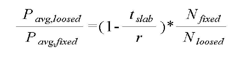
where tslab refers to a slab thickness, and r refers a curvature of radius of the strand guide. - The continuous casting machine of claim 4, wherein the number Nloosed of the rolls disposed the inner frame is greater than the number Nfixed of the rolls disposed on the outer frame (Nfixed<Nloosed).
- The continuous casting machine of claim 1, wherein the inner frame and the outer frame comprise pinch rolls, respectively, so as to draw the slab passing therebetween, and centers of the pinches of the inner frame and the outer frame are not aligned.
- The continuous casting machine of claim 1, wherein the outer frame is a fixed frame, and the inner frame is a loosed frame that is movable.
Applications Claiming Priority (2)
| Application Number | Priority Date | Filing Date | Title |
|---|---|---|---|
| KR1020110137468A KR101360552B1 (en) | 2011-12-19 | 2011-12-19 | Continuous Casting Device |
| PCT/KR2012/011091 WO2013094972A1 (en) | 2011-12-19 | 2012-12-18 | Continuous casting machine |
Publications (3)
| Publication Number | Publication Date |
|---|---|
| EP2796224A1 true EP2796224A1 (en) | 2014-10-29 |
| EP2796224A4 EP2796224A4 (en) | 2015-12-30 |
| EP2796224B1 EP2796224B1 (en) | 2017-08-09 |
Family
ID=48668794
Family Applications (1)
| Application Number | Title | Priority Date | Filing Date |
|---|---|---|---|
| EP12860513.6A Active EP2796224B1 (en) | 2011-12-19 | 2012-12-18 | Continuous casting machine |
Country Status (5)
| Country | Link |
|---|---|
| EP (1) | EP2796224B1 (en) |
| KR (1) | KR101360552B1 (en) |
| CN (1) | CN103998160B (en) |
| RU (1) | RU2586378C2 (en) |
| WO (1) | WO2013094972A1 (en) |
Families Citing this family (2)
| Publication number | Priority date | Publication date | Assignee | Title |
|---|---|---|---|---|
| AT519390B1 (en) | 2016-12-13 | 2020-09-15 | Primetals Technologies Austria GmbH | Method and device for controlling a continuous caster |
| KR102158988B1 (en) | 2018-12-27 | 2020-09-23 | 주식회사 에이프로젠케이아이씨 | Special steel alloys for continuous casting equipment and rolls of continuous casting equipment comprising the same |
Family Cites Families (13)
| Publication number | Priority date | Publication date | Assignee | Title |
|---|---|---|---|---|
| JP3008821B2 (en) * | 1994-07-29 | 2000-02-14 | 住友金属工業株式会社 | Continuous casting method and apparatus for thin slab |
| KR100241404B1 (en) * | 1995-07-20 | 2000-03-02 | 이구택 | Method and device for control of tundish nozzle |
| JPH11320059A (en) * | 1998-05-06 | 1999-11-24 | Sumitomo Metal Ind Ltd | Continuous casting equipment |
| KR100499623B1 (en) * | 1998-12-24 | 2005-09-26 | 주식회사 하이닉스반도체 | Internal command signal generator and its method |
| JP3305675B2 (en) * | 1999-04-09 | 2002-07-24 | 住友金属工業株式会社 | Finishing method of thin slab continuous casting |
| JP2005199302A (en) * | 2004-01-15 | 2005-07-28 | Jfe Steel Kk | Continuous casting method |
| AT414221B (en) * | 2004-06-09 | 2006-10-15 | Voest Alpine Ind Anlagen | CONTINUITY CASTING SYSTEM AND METHOD FOR OPTIONALLY CASTING A WIDE METAL STRIP OR MAXIMUM TWO MORE THAN MERRY METAL STRINGS |
| ITMI20051764A1 (en) * | 2005-09-22 | 2007-03-23 | Danieli Off Mecc | PROCESS AND PLANT FOR THE PRODUCTION OF METAL TAPES |
| AT503526B1 (en) * | 2006-04-25 | 2008-07-15 | Voest Alpine Ind Anlagen | SPRAY NOZZLE ADJUSTMENT |
| CA2645094C (en) * | 2006-07-07 | 2013-03-26 | Rotelec | Process for the continuous casting of flat metal products with electromagnetic stirring and implementation installation |
| JP4948375B2 (en) * | 2007-11-30 | 2012-06-06 | 新日鉄エンジニアリング株式会社 | Guide roll segment for continuous casting |
| KR101149294B1 (en) * | 2009-01-28 | 2012-05-25 | 현대제철 주식회사 | Method and device for reducing centerline segregation of continuously cast slab segments |
| CN201855931U (en) * | 2010-11-18 | 2011-06-08 | 马鞍山钢铁股份有限公司 | Cooling device of secondary cooling area for special-shaped blank continuous casting |
-
2011
- 2011-12-19 KR KR1020110137468A patent/KR101360552B1/en active Active
-
2012
- 2012-12-18 WO PCT/KR2012/011091 patent/WO2013094972A1/en not_active Ceased
- 2012-12-18 EP EP12860513.6A patent/EP2796224B1/en active Active
- 2012-12-18 CN CN201280062618.XA patent/CN103998160B/en not_active Expired - Fee Related
- 2012-12-18 RU RU2014129463/02A patent/RU2586378C2/en active
Also Published As
| Publication number | Publication date |
|---|---|
| EP2796224A4 (en) | 2015-12-30 |
| RU2586378C2 (en) | 2016-06-10 |
| CN103998160A (en) | 2014-08-20 |
| RU2014129463A (en) | 2016-02-20 |
| WO2013094972A1 (en) | 2013-06-27 |
| EP2796224B1 (en) | 2017-08-09 |
| KR20130070237A (en) | 2013-06-27 |
| KR101360552B1 (en) | 2014-02-11 |
| CN103998160B (en) | 2016-01-20 |
Similar Documents
| Publication | Publication Date | Title |
|---|---|---|
| EP3845330B1 (en) | Light reduction method for continuous casting of bloom plain-barrelled roll-roller combination | |
| US10226801B2 (en) | Casting product reduction apparatus | |
| JP2012066303A (en) | Continuous casting method and continuous casting apparatus of steel | |
| CA2947828A1 (en) | Method for continuous-casting slab | |
| CN105121062B (en) | Continuous Casting Method for Slabs for Extremely Thick Steel Plates | |
| CN111185584B (en) | Method and system for controlling casting blank of slab casting machine | |
| US20140290899A1 (en) | Process engineering measures in a continuous casting machine at the start of casting, at the end of casting and when producing a transitional piece | |
| EP2796224B1 (en) | Continuous casting machine | |
| CN109848383B (en) | A flexible reduction method for improving the internal quality of the slab | |
| CN202461109U (en) | Continuous casting and rolling complete equipment of lead strip for preparing grid | |
| KR20090098384A (en) | Bender Segments for Continuous Casting | |
| JP2011147985A (en) | Continuous casting method and apparatus | |
| JP2012086261A (en) | Light rolling reduction controlling method of cast slab in continuous casting | |
| CN210280604U (en) | Multi-flow straight arc-shaped wide flat blank continuous casting machine production line | |
| JP5707849B2 (en) | Control method of light reduction of slab in continuous casting | |
| CN220480193U (en) | Casting blank guiding device of ultra-high speed small square billet casting machine | |
| CN102430576B (en) | Complete continuous casting and rolling equipment for producing lead strips for grids | |
| KR100472531B1 (en) | The control method of driven roll pressure in continuous casting equipments | |
| CA1047221A (en) | Curved roller track for continuously cast ingots | |
| JP4417899B2 (en) | Continuous casting method | |
| KR101736574B1 (en) | Solidifying apparatus | |
| KR101280946B1 (en) | Segment for continous casting and continous casting method using same | |
| JP2012066302A (en) | Continuous casting method and continuous casting apparatus of steel | |
| KR20260058556A (en) | Apparatus for controlling shape of first slab, continuous casting method, and continuous casting slab | |
| JP5691912B2 (en) | Method for continuous casting of metal pieces |
Legal Events
| Date | Code | Title | Description |
|---|---|---|---|
| PUAI | Public reference made under article 153(3) epc to a published international application that has entered the european phase |
Free format text: ORIGINAL CODE: 0009012 |
|
| 17P | Request for examination filed |
Effective date: 20140703 |
|
| AK | Designated contracting states |
Kind code of ref document: A1 Designated state(s): AL AT BE BG CH CY CZ DE DK EE ES FI FR GB GR HR HU IE IS IT LI LT LU LV MC MK MT NL NO PL PT RO RS SE SI SK SM TR |
|
| DAX | Request for extension of the european patent (deleted) | ||
| RA4 | Supplementary search report drawn up and despatched (corrected) |
Effective date: 20151127 |
|
| RIC1 | Information provided on ipc code assigned before grant |
Ipc: B22D 11/12 20060101AFI20151123BHEP |
|
| GRAP | Despatch of communication of intention to grant a patent |
Free format text: ORIGINAL CODE: EPIDOSNIGR1 |
|
| INTG | Intention to grant announced |
Effective date: 20170308 |
|
| GRAS | Grant fee paid |
Free format text: ORIGINAL CODE: EPIDOSNIGR3 |
|
| GRAA | (expected) grant |
Free format text: ORIGINAL CODE: 0009210 |
|
| AK | Designated contracting states |
Kind code of ref document: B1 Designated state(s): AL AT BE BG CH CY CZ DE DK EE ES FI FR GB GR HR HU IE IS IT LI LT LU LV MC MK MT NL NO PL PT RO RS SE SI SK SM TR |
|
| REG | Reference to a national code |
Ref country code: GB Ref legal event code: FG4D |
|
| REG | Reference to a national code |
Ref country code: CH Ref legal event code: EP Ref country code: AT Ref legal event code: REF Ref document number: 916269 Country of ref document: AT Kind code of ref document: T Effective date: 20170815 |
|
| REG | Reference to a national code |
Ref country code: IE Ref legal event code: FG4D |
|
| REG | Reference to a national code |
Ref country code: DE Ref legal event code: R096 Ref document number: 602012035834 Country of ref document: DE |
|
| REG | Reference to a national code |
Ref country code: NL Ref legal event code: MP Effective date: 20170809 |
|
| REG | Reference to a national code |
Ref country code: LT Ref legal event code: MG4D |
|
| PG25 | Lapsed in a contracting state [announced via postgrant information from national office to epo] |
Ref country code: NL Free format text: LAPSE BECAUSE OF FAILURE TO SUBMIT A TRANSLATION OF THE DESCRIPTION OR TO PAY THE FEE WITHIN THE PRESCRIBED TIME-LIMIT Effective date: 20170809 Ref country code: SE Free format text: LAPSE BECAUSE OF FAILURE TO SUBMIT A TRANSLATION OF THE DESCRIPTION OR TO PAY THE FEE WITHIN THE PRESCRIBED TIME-LIMIT Effective date: 20170809 Ref country code: HR Free format text: LAPSE BECAUSE OF FAILURE TO SUBMIT A TRANSLATION OF THE DESCRIPTION OR TO PAY THE FEE WITHIN THE PRESCRIBED TIME-LIMIT Effective date: 20170809 Ref country code: FI Free format text: LAPSE BECAUSE OF FAILURE TO SUBMIT A TRANSLATION OF THE DESCRIPTION OR TO PAY THE FEE WITHIN THE PRESCRIBED TIME-LIMIT Effective date: 20170809 Ref country code: LT Free format text: LAPSE BECAUSE OF FAILURE TO SUBMIT A TRANSLATION OF THE DESCRIPTION OR TO PAY THE FEE WITHIN THE PRESCRIBED TIME-LIMIT Effective date: 20170809 Ref country code: NO Free format text: LAPSE BECAUSE OF FAILURE TO SUBMIT A TRANSLATION OF THE DESCRIPTION OR TO PAY THE FEE WITHIN THE PRESCRIBED TIME-LIMIT Effective date: 20171109 |
|
| PG25 | Lapsed in a contracting state [announced via postgrant information from national office to epo] |
Ref country code: GR Free format text: LAPSE BECAUSE OF FAILURE TO SUBMIT A TRANSLATION OF THE DESCRIPTION OR TO PAY THE FEE WITHIN THE PRESCRIBED TIME-LIMIT Effective date: 20171110 Ref country code: IS Free format text: LAPSE BECAUSE OF FAILURE TO SUBMIT A TRANSLATION OF THE DESCRIPTION OR TO PAY THE FEE WITHIN THE PRESCRIBED TIME-LIMIT Effective date: 20171209 Ref country code: RS Free format text: LAPSE BECAUSE OF FAILURE TO SUBMIT A TRANSLATION OF THE DESCRIPTION OR TO PAY THE FEE WITHIN THE PRESCRIBED TIME-LIMIT Effective date: 20170809 Ref country code: LV Free format text: LAPSE BECAUSE OF FAILURE TO SUBMIT A TRANSLATION OF THE DESCRIPTION OR TO PAY THE FEE WITHIN THE PRESCRIBED TIME-LIMIT Effective date: 20170809 Ref country code: BG Free format text: LAPSE BECAUSE OF FAILURE TO SUBMIT A TRANSLATION OF THE DESCRIPTION OR TO PAY THE FEE WITHIN THE PRESCRIBED TIME-LIMIT Effective date: 20171109 Ref country code: PL Free format text: LAPSE BECAUSE OF FAILURE TO SUBMIT A TRANSLATION OF THE DESCRIPTION OR TO PAY THE FEE WITHIN THE PRESCRIBED TIME-LIMIT Effective date: 20170809 Ref country code: ES Free format text: LAPSE BECAUSE OF FAILURE TO SUBMIT A TRANSLATION OF THE DESCRIPTION OR TO PAY THE FEE WITHIN THE PRESCRIBED TIME-LIMIT Effective date: 20170809 |
|
| PG25 | Lapsed in a contracting state [announced via postgrant information from national office to epo] |
Ref country code: CZ Free format text: LAPSE BECAUSE OF FAILURE TO SUBMIT A TRANSLATION OF THE DESCRIPTION OR TO PAY THE FEE WITHIN THE PRESCRIBED TIME-LIMIT Effective date: 20170809 Ref country code: DK Free format text: LAPSE BECAUSE OF FAILURE TO SUBMIT A TRANSLATION OF THE DESCRIPTION OR TO PAY THE FEE WITHIN THE PRESCRIBED TIME-LIMIT Effective date: 20170809 Ref country code: RO Free format text: LAPSE BECAUSE OF FAILURE TO SUBMIT A TRANSLATION OF THE DESCRIPTION OR TO PAY THE FEE WITHIN THE PRESCRIBED TIME-LIMIT Effective date: 20170809 |
|
| REG | Reference to a national code |
Ref country code: DE Ref legal event code: R097 Ref document number: 602012035834 Country of ref document: DE |
|
| PG25 | Lapsed in a contracting state [announced via postgrant information from national office to epo] |
Ref country code: EE Free format text: LAPSE BECAUSE OF FAILURE TO SUBMIT A TRANSLATION OF THE DESCRIPTION OR TO PAY THE FEE WITHIN THE PRESCRIBED TIME-LIMIT Effective date: 20170809 Ref country code: SM Free format text: LAPSE BECAUSE OF FAILURE TO SUBMIT A TRANSLATION OF THE DESCRIPTION OR TO PAY THE FEE WITHIN THE PRESCRIBED TIME-LIMIT Effective date: 20170809 Ref country code: SK Free format text: LAPSE BECAUSE OF FAILURE TO SUBMIT A TRANSLATION OF THE DESCRIPTION OR TO PAY THE FEE WITHIN THE PRESCRIBED TIME-LIMIT Effective date: 20170809 |
|
| PLBE | No opposition filed within time limit |
Free format text: ORIGINAL CODE: 0009261 |
|
| STAA | Information on the status of an ep patent application or granted ep patent |
Free format text: STATUS: NO OPPOSITION FILED WITHIN TIME LIMIT |
|
| REG | Reference to a national code |
Ref country code: DE Ref legal event code: R119 Ref document number: 602012035834 Country of ref document: DE |
|
| 26N | No opposition filed |
Effective date: 20180511 |
|
| REG | Reference to a national code |
Ref country code: CH Ref legal event code: PL |
|
| GBPC | Gb: european patent ceased through non-payment of renewal fee |
Effective date: 20171218 |
|
| PG25 | Lapsed in a contracting state [announced via postgrant information from national office to epo] |
Ref country code: SI Free format text: LAPSE BECAUSE OF FAILURE TO SUBMIT A TRANSLATION OF THE DESCRIPTION OR TO PAY THE FEE WITHIN THE PRESCRIBED TIME-LIMIT Effective date: 20170809 |
|
| REG | Reference to a national code |
Ref country code: IE Ref legal event code: MM4A |
|
| PG25 | Lapsed in a contracting state [announced via postgrant information from national office to epo] |
Ref country code: MT Free format text: LAPSE BECAUSE OF NON-PAYMENT OF DUE FEES Effective date: 20171218 Ref country code: LU Free format text: LAPSE BECAUSE OF NON-PAYMENT OF DUE FEES Effective date: 20171218 |
|
| REG | Reference to a national code |
Ref country code: FR Ref legal event code: ST Effective date: 20180831 |
|
| REG | Reference to a national code |
Ref country code: BE Ref legal event code: MM Effective date: 20171231 |
|
| PG25 | Lapsed in a contracting state [announced via postgrant information from national office to epo] |
Ref country code: FR Free format text: LAPSE BECAUSE OF NON-PAYMENT OF DUE FEES Effective date: 20180102 Ref country code: DE Free format text: LAPSE BECAUSE OF NON-PAYMENT OF DUE FEES Effective date: 20180703 Ref country code: IE Free format text: LAPSE BECAUSE OF NON-PAYMENT OF DUE FEES Effective date: 20171218 |
|
| PG25 | Lapsed in a contracting state [announced via postgrant information from national office to epo] |
Ref country code: LI Free format text: LAPSE BECAUSE OF NON-PAYMENT OF DUE FEES Effective date: 20171231 Ref country code: GB Free format text: LAPSE BECAUSE OF NON-PAYMENT OF DUE FEES Effective date: 20171218 Ref country code: BE Free format text: LAPSE BECAUSE OF NON-PAYMENT OF DUE FEES Effective date: 20171231 Ref country code: CH Free format text: LAPSE BECAUSE OF NON-PAYMENT OF DUE FEES Effective date: 20171231 |
|
| REG | Reference to a national code |
Ref country code: AT Ref legal event code: UEP Ref document number: 916269 Country of ref document: AT Kind code of ref document: T Effective date: 20170809 |
|
| PG25 | Lapsed in a contracting state [announced via postgrant information from national office to epo] |
Ref country code: MC Free format text: LAPSE BECAUSE OF FAILURE TO SUBMIT A TRANSLATION OF THE DESCRIPTION OR TO PAY THE FEE WITHIN THE PRESCRIBED TIME-LIMIT Effective date: 20170809 Ref country code: HU Free format text: LAPSE BECAUSE OF FAILURE TO SUBMIT A TRANSLATION OF THE DESCRIPTION OR TO PAY THE FEE WITHIN THE PRESCRIBED TIME-LIMIT; INVALID AB INITIO Effective date: 20121218 |
|
| PG25 | Lapsed in a contracting state [announced via postgrant information from national office to epo] |
Ref country code: CY Free format text: LAPSE BECAUSE OF FAILURE TO SUBMIT A TRANSLATION OF THE DESCRIPTION OR TO PAY THE FEE WITHIN THE PRESCRIBED TIME-LIMIT Effective date: 20170809 |
|
| PG25 | Lapsed in a contracting state [announced via postgrant information from national office to epo] |
Ref country code: MK Free format text: LAPSE BECAUSE OF FAILURE TO SUBMIT A TRANSLATION OF THE DESCRIPTION OR TO PAY THE FEE WITHIN THE PRESCRIBED TIME-LIMIT Effective date: 20170809 |
|
| PG25 | Lapsed in a contracting state [announced via postgrant information from national office to epo] |
Ref country code: TR Free format text: LAPSE BECAUSE OF FAILURE TO SUBMIT A TRANSLATION OF THE DESCRIPTION OR TO PAY THE FEE WITHIN THE PRESCRIBED TIME-LIMIT Effective date: 20170809 |
|
| PG25 | Lapsed in a contracting state [announced via postgrant information from national office to epo] |
Ref country code: PT Free format text: LAPSE BECAUSE OF FAILURE TO SUBMIT A TRANSLATION OF THE DESCRIPTION OR TO PAY THE FEE WITHIN THE PRESCRIBED TIME-LIMIT Effective date: 20170809 |
|
| PG25 | Lapsed in a contracting state [announced via postgrant information from national office to epo] |
Ref country code: AL Free format text: LAPSE BECAUSE OF FAILURE TO SUBMIT A TRANSLATION OF THE DESCRIPTION OR TO PAY THE FEE WITHIN THE PRESCRIBED TIME-LIMIT Effective date: 20170809 |
|
| PGFP | Annual fee paid to national office [announced via postgrant information from national office to epo] |
Ref country code: AT Payment date: 20211220 Year of fee payment: 10 |
|
| REG | Reference to a national code |
Ref country code: AT Ref legal event code: PC Ref document number: 916269 Country of ref document: AT Kind code of ref document: T Owner name: POSCO CO., LTD, KR Effective date: 20230228 |
|
| REG | Reference to a national code |
Ref country code: AT Ref legal event code: MM01 Ref document number: 916269 Country of ref document: AT Kind code of ref document: T Effective date: 20221218 |
|
| PG25 | Lapsed in a contracting state [announced via postgrant information from national office to epo] |
Ref country code: AT Free format text: LAPSE BECAUSE OF NON-PAYMENT OF DUE FEES Effective date: 20221218 |
|
| PGFP | Annual fee paid to national office [announced via postgrant information from national office to epo] |
Ref country code: IT Payment date: 20251121 Year of fee payment: 14 |