EP2795041B1 - Flexible routing device for well intervention - Google Patents
Flexible routing device for well intervention Download PDFInfo
- Publication number
- EP2795041B1 EP2795041B1 EP12818651.7A EP12818651A EP2795041B1 EP 2795041 B1 EP2795041 B1 EP 2795041B1 EP 12818651 A EP12818651 A EP 12818651A EP 2795041 B1 EP2795041 B1 EP 2795041B1
- Authority
- EP
- European Patent Office
- Prior art keywords
- conduit device
- drum
- intervention string
- string
- path
- Prior art date
- Legal status (The legal status is an assumption and is not a legal conclusion. Google has not performed a legal analysis and makes no representation as to the accuracy of the status listed.)
- Active
Links
Images



Classifications
-
- E—FIXED CONSTRUCTIONS
- E21—EARTH OR ROCK DRILLING; MINING
- E21B—EARTH OR ROCK DRILLING; OBTAINING OIL, GAS, WATER, SOLUBLE OR MELTABLE MATERIALS OR A SLURRY OF MINERALS FROM WELLS
- E21B19/00—Handling rods, casings, tubes or the like outside the borehole, e.g. in the derrick; Apparatus for feeding the rods or cables
- E21B19/22—Handling reeled pipe or rod units, e.g. flexible drilling pipes
-
- E—FIXED CONSTRUCTIONS
- E21—EARTH OR ROCK DRILLING; MINING
- E21B—EARTH OR ROCK DRILLING; OBTAINING OIL, GAS, WATER, SOLUBLE OR MELTABLE MATERIALS OR A SLURRY OF MINERALS FROM WELLS
- E21B19/00—Handling rods, casings, tubes or the like outside the borehole, e.g. in the derrick; Apparatus for feeding the rods or cables
Definitions
- the present invention relates to a conduit device for a petroleum well intervention string for guiding the intervention string, such as a carbon fibre reinforced rod containing electrical conductors and / or signal fibres, between a drum unit on deck and an intervention string injector on a wellhead.
- a conduit device for a petroleum well intervention string for guiding the intervention string, such as a carbon fibre reinforced rod containing electrical conductors and / or signal fibres, between a drum unit on deck and an intervention string injector on a wellhead.
- wireline drum units are placed near the wellhead unit and aligned with the gooseneck on the wellhead unit and must have cleared a free straight path, also along the deck below, for the intervention string to hang in a catenary line between the drum and the gooseneck on the wellhead unit.
- Temporary differences in speed between the drum and the injector head are taken up in the slack catenary line. This slack line and the fixed spatial requirements excludes other operations in the area, and further poses a risk to personal injury and damage to the intervention string.
- WO2011/096820 describes a series of ball-and-socket bending restrictor element pipe sections comprising pipe sections with ball-only ends for being linked using longitudinally split socket-only sleeves with locking elements. That bending restrictor is used over goosenecks.
- US 2004/0118556 A1 discloses a system comprising a conduit device for a petroleum well intervention string, said conduit device being connected to a drum unit and to an injector head.
- the conduit has at any point a radius of curvature larger than or equal to the smallest allowable radius of curvature for said intervention string, and forms a substantially incompressible fixed length tubular path for the intervention string.
- the present invention is a conduit device (7) for a petroleum well intervention string (0).
- the conduit device comprises a first end (72) arranged for being connected to an intervention string drum unit (100) with a drum (101), and a second end (73) connected to an injector head (202) of a wellhead assembly (200). Please see Fig. 6a for a general setup of the invention.
- the conduit device (7) of the invention at any point between said first end (72) and said second end (73), has a radius of curvature (R) larger than or equal to a given smallest allowable radius of curvature (R0) for said intervention string (0).
- the conduit device (7) of the invention fors a substantially incompressible fixed length path for the portion of said intervention string (0) at any time present between said first end (72) and said second end (73). Further, the conduit device (7) of the invention constitutes a tubular path for the intervention string (0).
- any straight pipe will satisfy, and any pipe bend or bending restrictor used, must satisfy the requirement "having a radius of curvature (R) larger than the smallest allowable radius of curvature (R0). Please see Fig. 8 showing places where the radius of curvature satisfies this requirement.
- tubular used here means pipe-shaped, pipe bend, hose-shaped, tunnel or hole, i.e. any closed channel adapted for and wherein the intervention string runs.
- incompressible is exemplified by such as a metal pipe, fibre reinforced tubes, a chain of ball-and-socket type bending restrictor elements made in metal or a hardened polymer material, please see an example in Figs. 1 , 3 , 4 , and 5a-f .
- conduit device (7) is incompressible results in that the intervention string tension is substantially maintained (except for friction loss) at all times along all the path between the injector head (204) and the drum unit (100).
- conduit device (7) being tubular prevents mechanical contact between the string (0) and anything external to the conduit device (7) and also protects the string (0) from wear and crushing damage. This feature further protects personnel's health by preventing personal injury by mechanical contact with the running string (0) or chemical contact with the possibly polluted string (0).
- Fig. 8 it comprises one or more sections of straight pipe (75) of extensive length.
- Fig. 8 An example is illustrated in Fig. 8 wherein the drum unit is placed at a first deck level of a petroleum rig or vessel, and the conduit device with the intervention string running within is extended via a second deck level through bends and a fixed straight pipe section to a flexible bend restrictor to a gooseneck (204) on an injector head (202) at a wellhead assembly (200). Beyond the wellhead assembly the intervention string extends according to desire into the well.
- any point between said first end (72) and said second end (73) has a radius of curvature (R) larger than or equal to a given smallest allowable radius of curvature (R0) for said intervention string (0).
- R radius of curvature
- R0 radius of curvature
- the conduit device (7) comprises one or more pipe bend (76) of fixed curvature.
- the conduit device (7) of the invention is laterally flexible along at least a portion of its path between the first end (72) and the second end (73). Examples of this is shown in Figs. 6a , 6b, and 6c , and in Fig. 8 for the section between a terminal point (105) on the drum frame (102) and the clamp (79) for the fixed pipe bend, and between the fixed pipe bend near the second deck level at the clamp (79) where the bend restrictor is allowed to flex laterally (but not longitudinally) until it runs over the gooseneck (204).
- An advantage of the present invention is that one may place the intervention drum at a significant distance from the wellhead unit, more than 80 metres in total distance as counted along the conduit device has been tested, and the requirement of alignment and a free straight path for the intervention string hanging in a catenary line between the drum and the wellhead unit may be disposed with.
- the conduit device (7) comprises in an embodiment of the invention one or more ball-and-socket type bend restrictor elements (2), please see Fig. 1 , 2 , 3, 4 , 5a-f , 6a , 6b , 6c , 7 , 8 , 9 , forming flexible bend restrictor sections along the path between said first end (72) and said second end (73).
- These ball-and socket connections may be comprised in a series of non-fixed bend restrictor pipes (2), so-called "knuckle jointed” pipe connections, which allows to flex the path according to space requirements, and to move part of the conduit device if refurnishing of other equipment along the path on the petroleum rig is required.
- the conduit device (7) comprises one or more extensive sections of semi-stiff hose (77). Practical tests of more than 30 metres of stiff hose has been tried with success.
- the conduit device (7) of the invention may have the first end (72) attached at a terminal point (105) of a drum frame (102) of said drum unit (100).
- said drum frame (102) is provided with a tension compensator arch (103) arranged between said terminal point (105) and said drum (101).
- any temporary speed differences due to different inertia of the string (0), the injector head (204) and the drum (101) are taken up by the tension compensator arch (103).
- the conduit device of the invention not only forms an incompressible length path, but also forms a substantially inextendable fixed length path for said portion of said intervention string running or residing between said first end (72) and said second end (73), i.e. that all the tubular components may not be extended nor pulled apart in their longitudinal direction.
- This is achieved by the lockable but rotatable ball- and socket connectors illustrated in Fig. 5a-f and the corresponding end pieces with a flange and a ball connector or a socket connector. Pipes may also have ordinary flange or screw connections.
- conduit device (7) is not torn apart by an incompressible, semi-rigid composite rod or tubing intervention string (0) which is subject to compressive forces either due to being pushed through the conduit device (7) or due to temporary speed differences between the injector head (204) and the drum (100).
- conduit device is laid over or attached to a gooseneck (204) arranged at said second end (73) at the wellhead.
- the conduit device of may comprise a combination of components. It may comprise flange connections (78) with either a ball connector (21) or a socket type connector (22) in the opposite end.
- the flange connections may be used as end or intermittent connections so as for allowing connection of any of: the drum frame (102), the bend restrictor element pipes (2), the pipe bends (76), the straight pipe sections (75), possible semi-stiff hoses (77), and an entry point of said injector head (202).
Landscapes
- Engineering & Computer Science (AREA)
- Geology (AREA)
- Life Sciences & Earth Sciences (AREA)
- Mining & Mineral Resources (AREA)
- Physics & Mathematics (AREA)
- Environmental & Geological Engineering (AREA)
- Fluid Mechanics (AREA)
- Mechanical Engineering (AREA)
- General Life Sciences & Earth Sciences (AREA)
- Geochemistry & Mineralogy (AREA)
- Excavating Of Shafts Or Tunnels (AREA)
- Electrical Discharge Machining, Electrochemical Machining, And Combined Machining (AREA)
- Supplying Of Containers To The Packaging Station (AREA)
- Steering Control In Accordance With Driving Conditions (AREA)
Description
- The present invention relates to a conduit device for a petroleum well intervention string for guiding the intervention string, such as a carbon fibre reinforced rod containing electrical conductors and / or signal fibres, between a drum unit on deck and an intervention string injector on a wellhead.
- Traditionally wireline drum units are placed near the wellhead unit and aligned with the gooseneck on the wellhead unit and must have cleared a free straight path, also along the deck below, for the intervention string to hang in a catenary line between the drum and the gooseneck on the wellhead unit. Temporary differences in speed between the drum and the injector head are taken up in the slack catenary line. This slack line and the fixed spatial requirements excludes other operations in the area, and further poses a risk to personal injury and damage to the intervention string.
-
WO2011/096820 describes a series of ball-and-socket bending restrictor element pipe sections comprising pipe sections with ball-only ends for being linked using longitudinally split socket-only sleeves with locking elements. That bending restrictor is used over goosenecks.US 2004/0118556 A1 discloses a system comprising a conduit device for a petroleum well intervention string, said conduit device being connected to a drum unit and to an injector head. The conduit has at any point a radius of curvature larger than or equal to the smallest allowable radius of curvature for said intervention string, and forms a substantially incompressible fixed length tubular path for the intervention string. - A solution to the above problem is provided by a system as in
claim 1. Further advantageous features are defined in the dependent claims attached. - Advantages of the invention are mentioned under the heading "Embodiments of the invention" below.
-
-
Fig. 1 shows a bend restrictor (1) of the invention bent into an arch, a semi-circle with a minimum allowed bending radius of R0 shown in side view and in end view of the arch. The pipe sections (2) are generally rotational symmetric about their local longitudinal axis and are provided with ball-and-socket connectors so the bend restrictor arch is not limited to any fixed plane. -
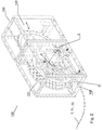
Fig. 2 is a perspective (isometric) illustration of an intervention drum unit (100) which may be used with the invention. The drum unit (100) comprises an intervention string drum (101) arranged laterally translatable within a steel frame (102) and provided with a string tension compensator (103) arranged for taking up temporary differences between the injector head (202) and the drum (101) now as the length of the intervention string (0) part residing between the entry point (105) of the frame (102) and the injector head (202) is constant. Part of the conduit device (7) of the invention is seen attached to the entry point (105). -
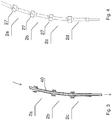
Fig. 3 is a section view of a bend restrictor of the invention comprising a series of generally identical pipe sections with a ball-and socket type connectors, the ball at a first end and the spherical zone socket at the opposite end. In the embodiment illustrated there is inserted a low friction polymer tube through the bend restrictor so as for guiding the intervention string and reducing friction and wear. -
Fig. 4 is a side view of the same. -
Figs. 5a to 5f are illustrations of a single pipe section (2) (2a, 2b, 2c ...) forming elements from which the bend restrictor of the invention is assembled. -
Fig. 5a is a side view of a single pipe section of the invention, the left part showing a locking ring at the receptacle or socket end, and the right part showing a corresponding ball-part end for being inserted into a socket end of a next pipe section. An end view of the locking ring and the socket end is shown. -
Fig. 5b is a section view of the same, showing the locking ring in the locking position about the socket end. A sphere of the internal radius of the socket end is shown, please seeFig. 7 for principal details. -
Fig. 5c is an isometric "perspective" view of the same pipe section of the invention. -
Figs. 5d, 5e, 5f correspond toFig. 5a, 5b, and 5c , with the difference of the locking ring being moved to the unlock position which allows the resilient segment sectors (26) of the socket to flex outward and release the ball part (21) -
Fig. 6a is a perspective illustration of a wellhead with an injector head in a steel frame, the conduit device (7) here constituted by a flexible bend restrictor (1) laid over a gooseneck attached to the steel frame, the bend restrictor (1) forming a closed, fixed length path between the injector head (202) and the steel frame (102) of the motorized drum unit (100) with a large-diameter drum (101) and a tension compensator arch (103). The push-through threading direction for the intervention string for the particular unidirectional bending restrictor type illustrated inFigs. 1 and5a-f is illustrated by a broken line arrow. -
Fig. 6b is a side elevation view of the same, andFig. 6c is a top view of the same. -
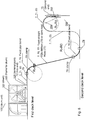
Fig. 7 is a principle illustration of a spherical segment: a solid defined by cutting a sphere with a pair of parallel planes. The surface of the spherical segment is called the spherical zone, excluding the planar bases. In the present invention the spherical zone is specified to have the two parallel planes arranged at either sides of the sphere's centre (c). This limitation is simply to arrange the spherical zone of the ball connector (21) to be retained within the similarly shaped corresponding spherical zone of socket connector (22) of substantially the same radius, of which the inner surface is illustrated with an exaggerated radius. -
Fig. 8 is an example illustration of the present invention wherein the drum unit is arranged at a first deck level of a petroleum platform and the conduit device is led via a second deck level to a wellhead unit (200). -
Fig. 9 is an illustration of a termination connector unit with a ball type joint and a flange heading towards the drum's end, here the entry point (105) at the drum frame (102), and a spherical socket-type connector with a flange for being connected towards the injector head's end. Flange connections may be replaced by weld joints, threaded joints, according to the designer's desire. - The present invention is a conduit device (7) for a petroleum well intervention string (0). The conduit device comprises a first end (72) arranged for being connected to an intervention string drum unit (100) with a drum (101), and a second end (73) connected to an injector head (202) of a wellhead assembly (200). Please see
Fig. 6a for a general setup of the invention. The conduit device (7) of the invention, at any point between said first end (72) and said second end (73), has a radius of curvature (R) larger than or equal to a given smallest allowable radius of curvature (R0) for said intervention string (0). Further, the conduit device (7) of the invention fors a substantially incompressible fixed length path for the portion of said intervention string (0) at any time present between said first end (72) and said second end (73). Further, the conduit device (7) of the invention constitutes a tubular path for the intervention string (0). In this context, any straight pipe will satisfy, and any pipe bend or bending restrictor used, must satisfy the requirement "having a radius of curvature (R) larger than the smallest allowable radius of curvature (R0). Please seeFig. 8 showing places where the radius of curvature satisfies this requirement. - The term "tubular" used here means pipe-shaped, pipe bend, hose-shaped, tunnel or hole, i.e. any closed channel adapted for and wherein the intervention string runs. The notion "incompressible" is exemplified by such as a metal pipe, fibre reinforced tubes, a chain of ball-and-socket type bending restrictor elements made in metal or a hardened polymer material, please see an example in
Figs. 1 ,3 ,4 , and5a-f . - An advantage of the present invention is that the conduit device (7) is incompressible results in that the intervention string tension is substantially maintained (except for friction loss) at all times along all the path between the injector head (204) and the drum unit (100).
- An advantage by the invention by the feature that the conduit device (7) being tubular prevents mechanical contact between the string (0) and anything external to the conduit device (7) and also protects the string (0) from wear and crushing damage. This feature further protects personnel's health by preventing personal injury by mechanical contact with the running string (0) or chemical contact with the possibly polluted string (0).
- In an embodiment of the invention it comprises one or more sections of straight pipe (75) of extensive length. An example is illustrated in
Fig. 8 wherein the drum unit is placed at a first deck level of a petroleum rig or vessel, and the conduit device with the intervention string running within is extended via a second deck level through bends and a fixed straight pipe section to a flexible bend restrictor to a gooseneck (204) on an injector head (202) at a wellhead assembly (200). Beyond the wellhead assembly the intervention string extends according to desire into the well. - In an embodiment of the invention, at any point between said first end (72) and said second end (73) has a radius of curvature (R) larger than or equal to a given smallest allowable radius of curvature (R0) for said intervention string (0). This is in practice not optional but is a requirement regardless of how the conduit is made. It limits the amount of bending that the member can be subjected to. Elements are specified below, but include straight pipes, bends, stiff hoses, bend restrictor elements.
- In an embodiment of the invention, the conduit device (7) comprises one or more pipe bend (76) of fixed curvature.
- In an embodiment of the invention the conduit device (7) of the invention is laterally flexible along at least a portion of its path between the first end (72) and the second end (73). Examples of this is shown in
Figs. 6a ,6b, and 6c , and inFig. 8 for the section between a terminal point (105) on the drum frame (102) and the clamp (79) for the fixed pipe bend, and between the fixed pipe bend near the second deck level at the clamp (79) where the bend restrictor is allowed to flex laterally (but not longitudinally) until it runs over the gooseneck (204). - An advantage of the present invention is that one may place the intervention drum at a significant distance from the wellhead unit, more than 80 metres in total distance as counted along the conduit device has been tested, and the requirement of alignment and a free straight path for the intervention string hanging in a catenary line between the drum and the wellhead unit may be disposed with.
- The conduit device (7) comprises in an embodiment of the invention one or more ball-and-socket type bend restrictor elements (2), please see
Fig. 1 ,2 ,3, 4 ,5a-f ,6a ,6b ,6c ,7 ,8 ,9 , forming flexible bend restrictor sections along the path between said first end (72) and said second end (73). These ball-and socket connections may be comprised in a series of non-fixed bend restrictor pipes (2), so-called "knuckle jointed" pipe connections, which allows to flex the path according to space requirements, and to move part of the conduit device if refurnishing of other equipment along the path on the petroleum rig is required. - In an embodiment of the invention the conduit device (7) comprises one or more extensive sections of semi-stiff hose (77). Practical tests of more than 30 metres of stiff hose has been tried with success.
- The conduit device (7) of the invention may have the first end (72) attached at a terminal point (105) of a drum frame (102) of said drum unit (100). Preferably and advantageously, said drum frame (102) is provided with a tension compensator arch (103) arranged between said terminal point (105) and said drum (101). Advantageously, any temporary speed differences due to different inertia of the string (0), the injector head (204) and the drum (101) are taken up by the tension compensator arch (103).
- Preferably also, the conduit device of the invention not only forms an incompressible length path, but also forms a substantially inextendable fixed length path for said portion of said intervention string running or residing between said first end (72) and said second end (73), i.e. that all the tubular components may not be extended nor pulled apart in their longitudinal direction. This is achieved by the lockable but rotatable ball- and socket connectors illustrated in
Fig. 5a-f and the corresponding end pieces with a flange and a ball connector or a socket connector. Pipes may also have ordinary flange or screw connections. An advantage of this feature is that the conduit device (7) is not torn apart by an incompressible, semi-rigid composite rod or tubing intervention string (0) which is subject to compressive forces either due to being pushed through the conduit device (7) or due to temporary speed differences between the injector head (204) and the drum (100). - In an embodiment of the invention the conduit device is laid over or attached to a gooseneck (204) arranged at said second end (73) at the wellhead.
- The conduit device of may comprise a combination of components. It may comprise flange connections (78) with either a ball connector (21) or a socket type connector (22) in the opposite end. The flange connections may be used as end or intermittent connections so as for allowing connection of any of: the drum frame (102), the bend restrictor element pipes (2), the pipe bends (76), the straight pipe sections (75), possible semi-stiff hoses (77), and an entry point of said injector head (202).
Claims (9)
- A system comprising a conduit device (7) for a petroleum well intervention string (0) and a motorized intervention string drum unit (100) with a drum (101), wherein- a first end (72) of the conduit device (7) is connected to the motorized intervention string drum unit (100),- a second end (73) of the conduit device is connected to an injector head (202) of a wellhead assembly (200) said first end (72) attached at a terminal point (105) of a drum frame (102) of said drum unit (100), said drum frame (102) provided with a tension compensator arch (103) arranged between said terminal point (105) and said drum (101) so as to take up any temporary speed difference due to different inertia of the string (0),the injector head (204) and the drum (101),- said conduit device (7) at any point between said first end (72) and said second end (73) having a radius of curvature (R) larger than or equal to a given smallest allowable radius of curvature (R0) for said intervention string (0);- said conduit device (7) forming a substantially incompressible fixed length path for the portion of said intervention string (0) at any time present between said first end (72) and said second end (73);- said conduit device (7) constituting a tubular path for said intervention string (0).
- The system of claim 1, the conduit device comprising one or more sections of straight pipe (75) of extensive length.
- The system of claim 1 or 2, the conduit device comprising one or more pipe bend (76) of fixed curvature.
- The system of claim 1, 2, or 3, said conduit device (7) being laterally flexible along at least a portion of its path between said first end (72) and said second end (73),
- The system of any of the preceding claims, the conduit device comprising one or more ball-and-socket type bend restrictor elements (2) forming flexible bend restrictor sections along the path between said first end (72) and said second end (73).
- The system of any of the preceding claims, the conduit device comprising one or more sections of semi-stiff hose (77).
- The system of any of the preceding claims, said conduit device (7) comprising a gooseneck (204) arranged at said second end (73) at the wellhead.
- The system of any of the preceding claims, said conduit device (7) comprising flange connections (78) with either a ball connector (21) or a socket type connector (22) so as for allowing connection of any of:
said drum frame (102),
said bend restrictor element pipes (2),
said pipe bends (76),
said straight pipe sections (75),
said semi-stiff hoses (77),
and an entry point of said injector head (202). - The system of any of the preceding claims, the conduit device comprising a low friction polymer tube (40) through the conduit device so as for guiding the intervention string (0) and reducing friction and wear.
Applications Claiming Priority (3)
| Application Number | Priority Date | Filing Date | Title |
|---|---|---|---|
| US201161580098P | 2011-12-23 | 2011-12-23 | |
| NO20111775A NO340587B1 (en) | 2011-12-23 | 2011-12-23 | Flexible well intervention device |
| PCT/NO2012/050251 WO2013095157A2 (en) | 2011-12-23 | 2012-12-19 | Flexible routing device for well intervention |
Publications (2)
| Publication Number | Publication Date |
|---|---|
| EP2795041A2 EP2795041A2 (en) | 2014-10-29 |
| EP2795041B1 true EP2795041B1 (en) | 2017-08-30 |
Family
ID=48653412
Family Applications (1)
| Application Number | Title | Priority Date | Filing Date |
|---|---|---|---|
| EP12818651.7A Active EP2795041B1 (en) | 2011-12-23 | 2012-12-19 | Flexible routing device for well intervention |
Country Status (6)
| Country | Link |
|---|---|
| US (1) | US9228395B2 (en) |
| EP (1) | EP2795041B1 (en) |
| CA (1) | CA2858978C (en) |
| DK (1) | DK2795041T3 (en) |
| NO (1) | NO340587B1 (en) |
| WO (1) | WO2013095157A2 (en) |
Families Citing this family (5)
| Publication number | Priority date | Publication date | Assignee | Title |
|---|---|---|---|---|
| NO340587B1 (en) * | 2011-12-23 | 2017-05-15 | C6 Tech As | Flexible well intervention device |
| EP3365715B1 (en) | 2015-10-19 | 2020-12-02 | Commscope Technologies LLC | Articulating optical fiber guide system |
| WO2017086943A1 (en) | 2015-11-18 | 2017-05-26 | Halliburton Energy Services, Inc. | Segmented bend-limiter for slickline rope sockets and cable-heads |
| US11623263B2 (en) * | 2019-09-20 | 2023-04-11 | Kristian MARTIN | Bending apparatus for coiled tubing |
| US12208434B2 (en) | 2020-09-19 | 2025-01-28 | Kristian MARTIN | Bending apparatus for coiled tubing |
Citations (1)
| Publication number | Priority date | Publication date | Assignee | Title |
|---|---|---|---|---|
| US20030071160A1 (en) * | 1999-11-12 | 2003-04-17 | Varco I/P, Inc. | Reel spool and stand assembly for coiled tubing injector system |
Family Cites Families (56)
| Publication number | Priority date | Publication date | Assignee | Title |
|---|---|---|---|---|
| US689492A (en) | 1901-02-05 | 1901-12-24 | Johnson Hughes | Automatic brake. |
| US2453038A (en) * | 1945-05-05 | 1948-11-02 | Peter F Rossmann | One-piece sucker rod |
| US2810439A (en) | 1955-05-11 | 1957-10-22 | Mccullough Otis Johnson | Well head attachment for operating tools in a well under pressure |
| US2892535A (en) * | 1955-11-03 | 1959-06-30 | Cullen | Apparatus for handling hose or similar elongate members |
| DE1170126B (en) | 1959-07-02 | 1964-05-14 | Aloys Zeppenfeld Maschinenfabr | Device to prevent rope slack in heavy loads |
| US3429374A (en) * | 1967-08-21 | 1969-02-25 | Whetstine B Pridy | Oil well electrical cable tensioning |
| FR1583175A (en) * | 1967-09-28 | 1969-10-24 | ||
| US3524606A (en) | 1968-03-12 | 1970-08-18 | Lawrence Mfg Co | Cable reel mounting |
| US3479067A (en) * | 1968-05-06 | 1969-11-18 | Cicero C Brown | Flexible coupling |
| US3690409A (en) | 1968-10-21 | 1972-09-12 | Spider Staging Inc | Level winding winch mechanism and heavy-duty drive therefor |
| FR2044130A5 (en) | 1969-05-09 | 1971-02-19 | Creusot Forges Ateliers | |
| US3646798A (en) * | 1970-02-09 | 1972-03-07 | Fastener Eng Inc | Wire drawing apparatus and method |
| GB1401422A (en) | 1971-05-12 | 1975-07-16 | Brown Brothers & Co Ltd | Tow line shock absorber |
| US4091867A (en) * | 1977-01-14 | 1978-05-30 | Otis Engineering Corporation | Flexible conduit injection system |
| US4099403A (en) * | 1977-02-28 | 1978-07-11 | Rockford Manufacturing Group, Inc. | In-line wire drawing machine |
| US4125162A (en) * | 1977-05-13 | 1978-11-14 | Otis Engineering Corporation | Well flow system and method |
| US4464922A (en) * | 1978-12-12 | 1984-08-14 | Marshall Richards Barcro Limited | Wire drawing method and apparatus |
| US4492363A (en) | 1979-12-20 | 1985-01-08 | Niskin Shale J | Multiple pulley sheave assembly with retainer pulleys |
| JPS57141989U (en) | 1981-02-27 | 1982-09-06 | ||
| JPH072564B2 (en) | 1985-05-31 | 1995-01-18 | カヤバ工業株式会社 | Umbilical winch |
| US4947665A (en) * | 1989-03-23 | 1990-08-14 | Rockford Manufacturing Group, Inc. | Apparatus for the electrical control of an in-line drawing machine |
| EP0571207B1 (en) | 1992-05-20 | 1997-01-15 | SUPERWINCH LIMITED (Reg.No. 2708737) | Winch assembly |
| US5538092A (en) * | 1994-10-27 | 1996-07-23 | Ingersoll-Rand Company | Flexible drill pipe |
| GB2296001B (en) | 1994-12-17 | 1998-12-16 | Asep Bv | Winch apparatus |
| RU2151264C1 (en) * | 1996-06-05 | 2000-06-20 | Молчанов Александр Георгиевич | Unit with continuous string of flexible pipes for repair of wells equipped with sucker-rod pumps |
| US6006839A (en) * | 1996-10-02 | 1999-12-28 | Stewart & Stevenson, Inc. | Pressurized flexible conduit injection system |
| GB9802421D0 (en) * | 1998-02-06 | 1998-04-01 | Head Philip | A riser system for sub sea wells and method of operation |
| GB2334048B (en) * | 1998-02-06 | 1999-12-29 | Philip Head | Riser system for sub sea wells and method of operation |
| US6000656A (en) * | 1998-04-16 | 1999-12-14 | Rockford Manufacturing Group, Inc. | Space saving wire drawing machine with floor mounted wire coil |
| NL1011069C2 (en) * | 1999-01-19 | 2000-07-20 | Well Engineering Partners B V | Method and installation for inserting a pipe into a borehole in the ground. |
| DE19942608A1 (en) | 1999-08-31 | 2001-04-05 | Mannesmann Ag | Manual cable winch with drive crank, with holding element in region of cable groove edge to hold carrying cable in groove |
| US6761506B2 (en) * | 1999-11-29 | 2004-07-13 | Ihc Gusto Engineering B.V. | Pipe lay system with tension compensator |
| US6457534B1 (en) * | 2000-07-26 | 2002-10-01 | Schlumberger Technology Corporation | Method of reducing pipe fatigue by eliminating short movements |
| US8056639B2 (en) * | 2001-07-03 | 2011-11-15 | Emanuel Kulhanek | Well string injection system and method |
| US6516892B2 (en) * | 2001-06-26 | 2003-02-11 | Phillips Petroleum Company | Method and apparatus for coiled tubing operations |
| US6702519B2 (en) * | 2001-07-03 | 2004-03-09 | Torch Offshore, Inc. | Reel type pipeline laying ship and method |
| US6530432B2 (en) | 2001-07-11 | 2003-03-11 | Coiled Tubing Solutions, Inc. | Oil well tubing injection system and method |
| FR2843954B1 (en) | 2002-08-28 | 2005-04-08 | Kley France | DEVICE FOR CONTROLLING CABLE VOLTAGE ON A COOPERATING CABLE REEL WITH A WINCH, IN PARTICULAR A WINCH OF THE TYPE DIT A CABESTAN |
| CA2414764C (en) * | 2002-12-19 | 2007-11-13 | C-Tech Energy Services Inc. | Guide support for rig mounted continuous feed injection unit |
| US20040194963A1 (en) * | 2003-03-05 | 2004-10-07 | Torres Carlos A. | Subsea well workover system and method |
| US7051803B2 (en) * | 2003-03-24 | 2006-05-30 | Moretz Benny W | Enclosed radial wire-line cable conveying method and apparatus |
| FR2868408A1 (en) | 2004-04-01 | 2005-10-07 | Jean Jacques Cocagne | Pulley for deviating cables and belts in ship, has body receiving two sets of sheave wheels that are arranged such that they are tangential to circular arc, where wheels rotate around axis |
| GB0419781D0 (en) | 2004-09-07 | 2004-10-06 | Expro North Sea Ltd | Winch assembly |
| US7810556B2 (en) * | 2005-10-03 | 2010-10-12 | Havinga Richard D | Lubricator for use with coiled tubing apparatus and universal rig having coiled tubing and top drive capability |
| US7753344B1 (en) | 2007-11-19 | 2010-07-13 | Moretz Benny W | Pressurized wire line spool and method for using same in conjunction with a universal radial carrier |
| GB0803231D0 (en) | 2008-02-22 | 2008-04-02 | Qserv Ltd | Apparatus and method |
| NO332373B1 (en) * | 2008-08-13 | 2012-09-03 | C6 Technologies As | Coil assembly for an elongated element |
| KR101069840B1 (en) | 2009-04-06 | 2011-10-04 | 삼성중공업 주식회사 | Winch and autonomous mobile apparatus including the same |
| US20100263879A1 (en) * | 2009-04-13 | 2010-10-21 | Jamie Cochran | Spooled device guide system |
| NO20100174A1 (en) * | 2010-02-03 | 2011-08-04 | C6 Technologies As | Boyingsbegrenser |
| DE102010012263B3 (en) * | 2010-03-22 | 2011-07-28 | Wafios AG, 72764 | Device for controlling the drive of a reel |
| GB2479144B (en) * | 2010-03-30 | 2012-04-25 | Technip France | Pipeline laying apparatus and method |
| US20120111581A1 (en) * | 2010-11-04 | 2012-05-10 | Schlumberger Technology Corporation | Apparatus and method for reducing the residual bending and fatigue in coiled tubing |
| NO337443B1 (en) * | 2011-12-23 | 2016-04-11 | C6 Tech As | Drum unit for a well intervention string |
| NO340587B1 (en) * | 2011-12-23 | 2017-05-15 | C6 Tech As | Flexible well intervention device |
| US9482064B2 (en) * | 2012-05-30 | 2016-11-01 | C6 Technologies As | Drum unit with an arch compensator for a well intervention string |
-
2011
- 2011-12-23 NO NO20111775A patent/NO340587B1/en unknown
-
2012
- 2012-12-19 DK DK12818651.7T patent/DK2795041T3/en active
- 2012-12-19 EP EP12818651.7A patent/EP2795041B1/en active Active
- 2012-12-19 WO PCT/NO2012/050251 patent/WO2013095157A2/en not_active Ceased
- 2012-12-19 CA CA2858978A patent/CA2858978C/en active Active
- 2012-12-21 US US13/725,606 patent/US9228395B2/en active Active
Patent Citations (1)
| Publication number | Priority date | Publication date | Assignee | Title |
|---|---|---|---|---|
| US20030071160A1 (en) * | 1999-11-12 | 2003-04-17 | Varco I/P, Inc. | Reel spool and stand assembly for coiled tubing injector system |
Also Published As
| Publication number | Publication date |
|---|---|
| EP2795041A2 (en) | 2014-10-29 |
| WO2013095157A2 (en) | 2013-06-27 |
| CA2858978A1 (en) | 2013-06-27 |
| CA2858978C (en) | 2019-10-29 |
| DK2795041T3 (en) | 2017-12-04 |
| NO20111775A1 (en) | 2013-06-24 |
| US20130160988A1 (en) | 2013-06-27 |
| NO340587B1 (en) | 2017-05-15 |
| WO2013095157A3 (en) | 2014-01-03 |
| US9228395B2 (en) | 2016-01-05 |
Similar Documents
| Publication | Publication Date | Title |
|---|---|---|
| CA2858978C (en) | Flexible routing device for well intervention | |
| US7568861B2 (en) | Bend stiffener | |
| US9303795B2 (en) | Pipe-in-pipe apparatus including an engineered pipe | |
| CN102239611B (en) | Entry device for threading cables into existing pipe networks | |
| US11549314B2 (en) | Subsea riser systems | |
| CN107407548B (en) | Angular displacement of flexible pipe | |
| US20130255818A1 (en) | Interlocking Bend Limiter and Method of Assembly | |
| WO2011096820A2 (en) | A bend restrictor | |
| BR112014015538B1 (en) | METHOD OF MONITORING THE INTEGRITY OF A FLEXIBLE LINE, FLEXIBLE LINE, MEASUREMENT KIT AND A FLEXIBLE LINE MANUFACTURING PROCESS | |
| US20170022767A1 (en) | Cable protecting device | |
| US9742179B2 (en) | Conduit and end fitting for offshore cable assembly | |
| US7316269B1 (en) | Enclosed radial wire-line cable conveying method and apparatus | |
| US20170107770A1 (en) | Interface | |
| GB2531601A (en) | Assembling pipe-in-pipe systems and pipeline bundles | |
| US10697567B2 (en) | Flexible device and method | |
| US11555358B1 (en) | Method and apparatus for protection of control lines and other equipment | |
| EP1354231A2 (en) | Cable repeater connector | |
| US20140286708A1 (en) | Relating to pipelaying | |
| US9382780B1 (en) | Vertical swivel connection assembly and systems and methods for use thereof | |
| BRPI0902852A2 (en) | device and process for mounting a flexible conduit end tip into a frame and method for mounting a flexible conduit through a guide tube in a frame | |
| US20140338139A1 (en) | Pipeline Service Pig with Floating Seal Carriers | |
| WO2021127766A1 (en) | System for eliminating and removing hydrates and other blockages in undersea lines | |
| US20140338775A1 (en) | Bend Protector for a Pipeline Bend | |
| US20110214854A1 (en) | Attachment of control lines to outside of tubular | |
| BR102019028092B1 (en) | SYSTEM FOR COMBATING AND REMOVING HYDRATES AND OTHER BLOCKAGES IN SUBMARINE PIPELINES |
Legal Events
| Date | Code | Title | Description |
|---|---|---|---|
| PUAI | Public reference made under article 153(3) epc to a published international application that has entered the european phase |
Free format text: ORIGINAL CODE: 0009012 |
|
| 17P | Request for examination filed |
Effective date: 20140723 |
|
| AK | Designated contracting states |
Kind code of ref document: A2 Designated state(s): AL AT BE BG CH CY CZ DE DK EE ES FI FR GB GR HR HU IE IS IT LI LT LU LV MC MK MT NL NO PL PT RO RS SE SI SK SM TR |
|
| DAX | Request for extension of the european patent (deleted) | ||
| GRAP | Despatch of communication of intention to grant a patent |
Free format text: ORIGINAL CODE: EPIDOSNIGR1 |
|
| INTG | Intention to grant announced |
Effective date: 20170407 |
|
| GRAS | Grant fee paid |
Free format text: ORIGINAL CODE: EPIDOSNIGR3 |
|
| GRAA | (expected) grant |
Free format text: ORIGINAL CODE: 0009210 |
|
| AK | Designated contracting states |
Kind code of ref document: B1 Designated state(s): AL AT BE BG CH CY CZ DE DK EE ES FI FR GB GR HR HU IE IS IT LI LT LU LV MC MK MT NL NO PL PT RO RS SE SI SK SM TR |
|
| RAP1 | Party data changed (applicant data changed or rights of an application transferred) |
Owner name: C6 TECHNOLOGIES AS |
|
| REG | Reference to a national code |
Ref country code: GB Ref legal event code: FG4D |
|
| REG | Reference to a national code |
Ref country code: CH Ref legal event code: EP |
|
| REG | Reference to a national code |
Ref country code: AT Ref legal event code: REF Ref document number: 923741 Country of ref document: AT Kind code of ref document: T Effective date: 20170915 |
|
| REG | Reference to a national code |
Ref country code: IE Ref legal event code: FG4D |
|
| REG | Reference to a national code |
Ref country code: DE Ref legal event code: R096 Ref document number: 602012036726 Country of ref document: DE |
|
| REG | Reference to a national code |
Ref country code: FR Ref legal event code: PLFP Year of fee payment: 6 |
|
| REG | Reference to a national code |
Ref country code: DK Ref legal event code: T3 Effective date: 20171127 |
|
| REG | Reference to a national code |
Ref country code: NL Ref legal event code: MP Effective date: 20170830 |
|
| REG | Reference to a national code |
Ref country code: LT Ref legal event code: MG4D |
|
| REG | Reference to a national code |
Ref country code: AT Ref legal event code: MK05 Ref document number: 923741 Country of ref document: AT Kind code of ref document: T Effective date: 20170830 |
|
| PG25 | Lapsed in a contracting state [announced via postgrant information from national office to epo] |
Ref country code: SE Free format text: LAPSE BECAUSE OF FAILURE TO SUBMIT A TRANSLATION OF THE DESCRIPTION OR TO PAY THE FEE WITHIN THE PRESCRIBED TIME-LIMIT Effective date: 20170830 Ref country code: AT Free format text: LAPSE BECAUSE OF FAILURE TO SUBMIT A TRANSLATION OF THE DESCRIPTION OR TO PAY THE FEE WITHIN THE PRESCRIBED TIME-LIMIT Effective date: 20170830 Ref country code: FI Free format text: LAPSE BECAUSE OF FAILURE TO SUBMIT A TRANSLATION OF THE DESCRIPTION OR TO PAY THE FEE WITHIN THE PRESCRIBED TIME-LIMIT Effective date: 20170830 Ref country code: LT Free format text: LAPSE BECAUSE OF FAILURE TO SUBMIT A TRANSLATION OF THE DESCRIPTION OR TO PAY THE FEE WITHIN THE PRESCRIBED TIME-LIMIT Effective date: 20170830 Ref country code: HR Free format text: LAPSE BECAUSE OF FAILURE TO SUBMIT A TRANSLATION OF THE DESCRIPTION OR TO PAY THE FEE WITHIN THE PRESCRIBED TIME-LIMIT Effective date: 20170830 |
|
| REG | Reference to a national code |
Ref country code: NO Ref legal event code: T2 Effective date: 20170830 |
|
| PG25 | Lapsed in a contracting state [announced via postgrant information from national office to epo] |
Ref country code: ES Free format text: LAPSE BECAUSE OF FAILURE TO SUBMIT A TRANSLATION OF THE DESCRIPTION OR TO PAY THE FEE WITHIN THE PRESCRIBED TIME-LIMIT Effective date: 20170830 Ref country code: IS Free format text: LAPSE BECAUSE OF FAILURE TO SUBMIT A TRANSLATION OF THE DESCRIPTION OR TO PAY THE FEE WITHIN THE PRESCRIBED TIME-LIMIT Effective date: 20171230 Ref country code: RS Free format text: LAPSE BECAUSE OF FAILURE TO SUBMIT A TRANSLATION OF THE DESCRIPTION OR TO PAY THE FEE WITHIN THE PRESCRIBED TIME-LIMIT Effective date: 20170830 Ref country code: GR Free format text: LAPSE BECAUSE OF FAILURE TO SUBMIT A TRANSLATION OF THE DESCRIPTION OR TO PAY THE FEE WITHIN THE PRESCRIBED TIME-LIMIT Effective date: 20171201 Ref country code: BG Free format text: LAPSE BECAUSE OF FAILURE TO SUBMIT A TRANSLATION OF THE DESCRIPTION OR TO PAY THE FEE WITHIN THE PRESCRIBED TIME-LIMIT Effective date: 20171130 Ref country code: LV Free format text: LAPSE BECAUSE OF FAILURE TO SUBMIT A TRANSLATION OF THE DESCRIPTION OR TO PAY THE FEE WITHIN THE PRESCRIBED TIME-LIMIT Effective date: 20170830 |
|
| PG25 | Lapsed in a contracting state [announced via postgrant information from national office to epo] |
Ref country code: NL Free format text: LAPSE BECAUSE OF FAILURE TO SUBMIT A TRANSLATION OF THE DESCRIPTION OR TO PAY THE FEE WITHIN THE PRESCRIBED TIME-LIMIT Effective date: 20170830 |
|
| PG25 | Lapsed in a contracting state [announced via postgrant information from national office to epo] |
Ref country code: PL Free format text: LAPSE BECAUSE OF FAILURE TO SUBMIT A TRANSLATION OF THE DESCRIPTION OR TO PAY THE FEE WITHIN THE PRESCRIBED TIME-LIMIT Effective date: 20170830 Ref country code: CZ Free format text: LAPSE BECAUSE OF FAILURE TO SUBMIT A TRANSLATION OF THE DESCRIPTION OR TO PAY THE FEE WITHIN THE PRESCRIBED TIME-LIMIT Effective date: 20170830 Ref country code: RO Free format text: LAPSE BECAUSE OF FAILURE TO SUBMIT A TRANSLATION OF THE DESCRIPTION OR TO PAY THE FEE WITHIN THE PRESCRIBED TIME-LIMIT Effective date: 20170830 |
|
| PG25 | Lapsed in a contracting state [announced via postgrant information from national office to epo] |
Ref country code: SM Free format text: LAPSE BECAUSE OF FAILURE TO SUBMIT A TRANSLATION OF THE DESCRIPTION OR TO PAY THE FEE WITHIN THE PRESCRIBED TIME-LIMIT Effective date: 20170830 Ref country code: SK Free format text: LAPSE BECAUSE OF FAILURE TO SUBMIT A TRANSLATION OF THE DESCRIPTION OR TO PAY THE FEE WITHIN THE PRESCRIBED TIME-LIMIT Effective date: 20170830 Ref country code: IT Free format text: LAPSE BECAUSE OF FAILURE TO SUBMIT A TRANSLATION OF THE DESCRIPTION OR TO PAY THE FEE WITHIN THE PRESCRIBED TIME-LIMIT Effective date: 20170830 Ref country code: EE Free format text: LAPSE BECAUSE OF FAILURE TO SUBMIT A TRANSLATION OF THE DESCRIPTION OR TO PAY THE FEE WITHIN THE PRESCRIBED TIME-LIMIT Effective date: 20170830 |
|
| REG | Reference to a national code |
Ref country code: DE Ref legal event code: R097 Ref document number: 602012036726 Country of ref document: DE |
|
| REG | Reference to a national code |
Ref country code: DE Ref legal event code: R119 Ref document number: 602012036726 Country of ref document: DE |
|
| PLBE | No opposition filed within time limit |
Free format text: ORIGINAL CODE: 0009261 |
|
| STAA | Information on the status of an ep patent application or granted ep patent |
Free format text: STATUS: NO OPPOSITION FILED WITHIN TIME LIMIT |
|
| REG | Reference to a national code |
Ref country code: CH Ref legal event code: PL |
|
| 26N | No opposition filed |
Effective date: 20180531 |
|
| PG25 | Lapsed in a contracting state [announced via postgrant information from national office to epo] |
Ref country code: SI Free format text: LAPSE BECAUSE OF FAILURE TO SUBMIT A TRANSLATION OF THE DESCRIPTION OR TO PAY THE FEE WITHIN THE PRESCRIBED TIME-LIMIT Effective date: 20170830 |
|
| REG | Reference to a national code |
Ref country code: IE Ref legal event code: MM4A |
|
| PG25 | Lapsed in a contracting state [announced via postgrant information from national office to epo] |
Ref country code: MT Free format text: LAPSE BECAUSE OF NON-PAYMENT OF DUE FEES Effective date: 20171219 Ref country code: LU Free format text: LAPSE BECAUSE OF NON-PAYMENT OF DUE FEES Effective date: 20171219 |
|
| REG | Reference to a national code |
Ref country code: BE Ref legal event code: MM Effective date: 20171231 |
|
| PG25 | Lapsed in a contracting state [announced via postgrant information from national office to epo] |
Ref country code: IE Free format text: LAPSE BECAUSE OF NON-PAYMENT OF DUE FEES Effective date: 20171219 Ref country code: DE Free format text: LAPSE BECAUSE OF NON-PAYMENT OF DUE FEES Effective date: 20180703 |
|
| PG25 | Lapsed in a contracting state [announced via postgrant information from national office to epo] |
Ref country code: BE Free format text: LAPSE BECAUSE OF NON-PAYMENT OF DUE FEES Effective date: 20171231 Ref country code: LI Free format text: LAPSE BECAUSE OF NON-PAYMENT OF DUE FEES Effective date: 20171231 Ref country code: CH Free format text: LAPSE BECAUSE OF NON-PAYMENT OF DUE FEES Effective date: 20171231 |
|
| REG | Reference to a national code |
Ref country code: NO Ref legal event code: CREP Representative=s name: ZACCO NORWAY AS, POSTBOKS 2003 VIKA, 0125 OSLO |
|
| PG25 | Lapsed in a contracting state [announced via postgrant information from national office to epo] |
Ref country code: HU Free format text: LAPSE BECAUSE OF FAILURE TO SUBMIT A TRANSLATION OF THE DESCRIPTION OR TO PAY THE FEE WITHIN THE PRESCRIBED TIME-LIMIT; INVALID AB INITIO Effective date: 20121219 Ref country code: MC Free format text: LAPSE BECAUSE OF FAILURE TO SUBMIT A TRANSLATION OF THE DESCRIPTION OR TO PAY THE FEE WITHIN THE PRESCRIBED TIME-LIMIT Effective date: 20170830 |
|
| PG25 | Lapsed in a contracting state [announced via postgrant information from national office to epo] |
Ref country code: CY Free format text: LAPSE BECAUSE OF FAILURE TO SUBMIT A TRANSLATION OF THE DESCRIPTION OR TO PAY THE FEE WITHIN THE PRESCRIBED TIME-LIMIT Effective date: 20170830 |
|
| PG25 | Lapsed in a contracting state [announced via postgrant information from national office to epo] |
Ref country code: MK Free format text: LAPSE BECAUSE OF FAILURE TO SUBMIT A TRANSLATION OF THE DESCRIPTION OR TO PAY THE FEE WITHIN THE PRESCRIBED TIME-LIMIT Effective date: 20170830 |
|
| PG25 | Lapsed in a contracting state [announced via postgrant information from national office to epo] |
Ref country code: TR Free format text: LAPSE BECAUSE OF FAILURE TO SUBMIT A TRANSLATION OF THE DESCRIPTION OR TO PAY THE FEE WITHIN THE PRESCRIBED TIME-LIMIT Effective date: 20170830 |
|
| PG25 | Lapsed in a contracting state [announced via postgrant information from national office to epo] |
Ref country code: PT Free format text: LAPSE BECAUSE OF FAILURE TO SUBMIT A TRANSLATION OF THE DESCRIPTION OR TO PAY THE FEE WITHIN THE PRESCRIBED TIME-LIMIT Effective date: 20170830 |
|
| PG25 | Lapsed in a contracting state [announced via postgrant information from national office to epo] |
Ref country code: AL Free format text: LAPSE BECAUSE OF FAILURE TO SUBMIT A TRANSLATION OF THE DESCRIPTION OR TO PAY THE FEE WITHIN THE PRESCRIBED TIME-LIMIT Effective date: 20170830 |
|
| REG | Reference to a national code |
Ref country code: NO Ref legal event code: CHAD Owner name: COMTRAC AS, NO Ref country code: NO Ref legal event code: CHAD Owner name: C6 TECHNOLOGIES AS, NO |
|
| REG | Reference to a national code |
Ref country code: GB Ref legal event code: 732E Free format text: REGISTERED BETWEEN 20210415 AND 20210421 |
|
| P01 | Opt-out of the competence of the unified patent court (upc) registered |
Effective date: 20230524 |
|
| PGFP | Annual fee paid to national office [announced via postgrant information from national office to epo] |
Ref country code: GB Payment date: 20251015 Year of fee payment: 14 |
|
| PGFP | Annual fee paid to national office [announced via postgrant information from national office to epo] |
Ref country code: NO Payment date: 20251118 Year of fee payment: 14 |
|
| PGFP | Annual fee paid to national office [announced via postgrant information from national office to epo] |
Ref country code: DK Payment date: 20251015 Year of fee payment: 14 |
|
| PGFP | Annual fee paid to national office [announced via postgrant information from national office to epo] |
Ref country code: FR Payment date: 20251014 Year of fee payment: 14 |