EP2793055B1 - Radiation measurement device - Google Patents
Radiation measurement device Download PDFInfo
- Publication number
- EP2793055B1 EP2793055B1 EP12857540.4A EP12857540A EP2793055B1 EP 2793055 B1 EP2793055 B1 EP 2793055B1 EP 12857540 A EP12857540 A EP 12857540A EP 2793055 B1 EP2793055 B1 EP 2793055B1
- Authority
- EP
- European Patent Office
- Prior art keywords
- radiation
- intensity
- unit
- visible image
- radiation intensity
- Prior art date
- Legal status (The legal status is an assumption and is not a legal conclusion. Google has not performed a legal analysis and makes no representation as to the accuracy of the status listed.)
- Active
Links
- 230000005855 radiation Effects 0.000 title claims description 534
- 238000005259 measurement Methods 0.000 title claims description 192
- 238000009826 distribution Methods 0.000 claims description 183
- 230000033001 locomotion Effects 0.000 claims description 86
- 238000004364 calculation method Methods 0.000 claims description 30
- 239000003086 colorant Substances 0.000 claims description 18
- 230000000007 visual effect Effects 0.000 claims 1
- 238000010586 diagram Methods 0.000 description 48
- 238000000034 method Methods 0.000 description 47
- 238000012545 processing Methods 0.000 description 31
- 238000013500 data storage Methods 0.000 description 25
- 238000001514 detection method Methods 0.000 description 6
- 238000007726 management method Methods 0.000 description 6
- 238000005516 engineering process Methods 0.000 description 5
- 230000003068 static effect Effects 0.000 description 5
- 239000000284 extract Substances 0.000 description 4
- 230000006870 function Effects 0.000 description 3
- 238000012937 correction Methods 0.000 description 2
- 230000000694 effects Effects 0.000 description 2
- 230000005611 electricity Effects 0.000 description 2
- 238000003384 imaging method Methods 0.000 description 2
- 239000011159 matrix material Substances 0.000 description 2
- 230000003287 optical effect Effects 0.000 description 2
- 239000004065 semiconductor Substances 0.000 description 2
- 239000000758 substrate Substances 0.000 description 2
- 238000012546 transfer Methods 0.000 description 2
- 230000005540 biological transmission Effects 0.000 description 1
- 230000000295 complement effect Effects 0.000 description 1
- 230000007423 decrease Effects 0.000 description 1
- 230000003247 decreasing effect Effects 0.000 description 1
- 238000000605 extraction Methods 0.000 description 1
- 230000008014 freezing Effects 0.000 description 1
- 238000007710 freezing Methods 0.000 description 1
- 230000005251 gamma ray Effects 0.000 description 1
- 230000002452 interceptive effect Effects 0.000 description 1
- 238000011835 investigation Methods 0.000 description 1
- 230000005865 ionizing radiation Effects 0.000 description 1
- 230000001678 irradiating effect Effects 0.000 description 1
- 229910044991 metal oxide Inorganic materials 0.000 description 1
- 150000004706 metal oxides Chemical class 0.000 description 1
- 238000012986 modification Methods 0.000 description 1
- 230000004048 modification Effects 0.000 description 1
- 230000002093 peripheral effect Effects 0.000 description 1
- 230000001360 synchronised effect Effects 0.000 description 1
Images


Classifications
-
- G—PHYSICS
- G01—MEASURING; TESTING
- G01T—MEASUREMENT OF NUCLEAR OR X-RADIATION
- G01T1/00—Measuring X-radiation, gamma radiation, corpuscular radiation, or cosmic radiation
- G01T1/29—Measurement performed on radiation beams, e.g. position or section of the beam; Measurement of spatial distribution of radiation
- G01T1/2914—Measurement of spatial distribution of radiation
-
- G—PHYSICS
- G01—MEASURING; TESTING
- G01T—MEASUREMENT OF NUCLEAR OR X-RADIATION
- G01T1/00—Measuring X-radiation, gamma radiation, corpuscular radiation, or cosmic radiation
- G01T1/16—Measuring radiation intensity
-
- G—PHYSICS
- G01—MEASURING; TESTING
- G01T—MEASUREMENT OF NUCLEAR OR X-RADIATION
- G01T1/00—Measuring X-radiation, gamma radiation, corpuscular radiation, or cosmic radiation
- G01T1/16—Measuring radiation intensity
- G01T1/169—Exploration, location of contaminated surface areas
-
- G—PHYSICS
- G01—MEASURING; TESTING
- G01T—MEASUREMENT OF NUCLEAR OR X-RADIATION
- G01T7/00—Details of radiation-measuring instruments
-
- G—PHYSICS
- G06—COMPUTING; CALCULATING OR COUNTING
- G06T—IMAGE DATA PROCESSING OR GENERATION, IN GENERAL
- G06T11/00—2D [Two Dimensional] image generation
- G06T11/60—Editing figures and text; Combining figures or text
Definitions
- the present invention relates to a radiation measurement apparatus that measures an intensity distribution of radiation.
- the radiation measurement technology disclosed in patent document 1 includes a radiation detector that is arranged in two-dimensional arrangement such as a matrix or the like and a collimator that arranges in front of the radiation detector and limits incoming direction of radiation, and visualizes radiation intensity as two dimensional distribution.
- Patent Document 1 Publication of (Unexamined) Japanese Patent Application No. 2005-49136
- Patent document WO03/046611 discloses an ionizing radiation measurement apparatus comprising a visible and radiation intensity image acquisition unit and displaying an image by overlaying a radiation intensity image with a visible image using a plurality of colors allocated to the radiation intensity distribution (p.15, line 25 to p.16, line 2).
- Patent document JP2008188164 discloses a combined visible light camera and nuclear radiation imaging apparatus and discloses a motion correction device providing correction by shifting a plurality of radiation images a calculated shift amount upon motion of the object under investigation.
- the radiation measurement apparatus has a high portability or enables user to easily take it anywhere as well as that the radiation measurement apparatus can measure radiation with better precision.
- housing size of the radiation measurement apparatus gets larger. If carries the radiation measurement apparatus and uses it while user moves, since portability of the radiation measurement apparatus should be considered, it is required that the housing size fits within required size. As described above, since relation between portability and space resolution is incompatible (trade-off), there is a problem in that it become difficult to acquire radiation intensity distribution which has high resolution if the housing size is limited.
- the present invention has been made in consideration of the circumstances mentioned above, and an object thereof is to provide a radiation measurement apparatus that enables user to intuitively recognize a radiation measurement result. Further, the object of the present invention is to provide a radiation measurement apparatus that can improve resolution as well as portability.
- the present invention provides a radiation measurement apparatus according to claim 1.
- the present invention user can intuitively recognize a radiation measurement result. Further, the present invention can improve resolution as well as portability.
- Fig. 1 is a configuration diagram of a radiation measurement apparatus 10A that is an example of a radiation measurement apparatus.
- the radiation measurement apparatus 10A ( Fig. 1 ) includes a radiation detector 2A and an information processor 3A.
- the radiation detector 2A and the information processor 3A are connected so as to be capable of transmitting information each other.
- the radiation detector 2A has a visible image acquisition unit 11, a radiation intensity acquisition unit 12, and a position information acquisition unit 13.
- the visible image acquisition unit 11, the radiation intensity acquisition unit 12, and the position information acquisition unit 13 are accommodated in a housing 5 together.
- the visible image acquisition unit 11 is, for example, a camera including imaging element such as CCD (Charged Couple Device) or CMOS (Complementary Metal Oxide Semiconductor), and acquires one or more visible images.
- imaging element such as CCD (Charged Couple Device) or CMOS (Complementary Metal Oxide Semiconductor)
- CMOS Complementary Metal Oxide Semiconductor
- the radiation intensity acquisition unit 12 measures a radiation intensity distribution on 2D (two-dimensional) plane.
- the radiation intensity acquisition unit 12 includes a collimator, a plurality of detection elements (detector group), and a signal substrate.
- the collimator and leads radiation to the detector group.
- the detection elements are arranged on 2D plane or spherical surface in two-dimensional arrangement such as a matrix or the like.
- the detector group detect radiation such as gamma ray (y -ray).
- the signal substrate processes a detection signal output from the detector group.
- the visible image acquisition unit 11 and the radiation intensity acquisition unit 12 are respectively configured to be possible to acquire the visible image and the radiation intensity distribution from same direction.
- a unit configuration of the units 11 and 12 will be described hereunder ( Figs. 2 and 3 ).
- the position information acquisition unit 13 includes means for being possible to measure current position, such as GPS (Global Positioning System), and acquires position information of the radiation detector 2 (the visible image acquisition unit 11 and the radiation intensity acquisition unit 12).
- GPS Global Positioning System
- the information processor 3A is, for example, personal computer.
- the information processor 3A has an intensity display unit 15A, a data storage unit 16, a data search unit 17, and a date-time management unit 18.
- the information processor 3A further has an input unit that and an output unit that provides user with information such as processing result.
- the output unit has at least one unit selected from a display unit that visually outputs information, a sound output unit that soundly outputs information, and a print unit that outputs information as characters.
- the intensity display unit 15A allocates a plurality of colors to the radiation intensity acquired by the radiation intensity acquisition unit 12, and thereby expresses the radiation intensity by using allocated colors.
- the intensity display unit 15A displays the radiation intensity distribution that is expressed by using allocated colors and overlaid on the visible image.
- the intensity display unit 15A expresses the radiation intensity (image) by using grayscale or color (RGB) image.
- the intensity display unit 15A When grayscale image is used for expressing the radiation intensity, the intensity display unit 15A, for example, allocates black to maximum radiation intensity and white to minimum (zero) radiation intensity, and thereby expresses the radiation intensity by using black, white, and halftone between black and white in accordance with radiation intensity value.
- the intensity display unit 15A allocates red (R) to maximum radiation intensity, green (G) to middle radiation intensity, and blue (B) to minimum radiation intensity, and expresses radiation intensity by using red (R), green (G), blue (B), half color between red (R) and green (G), and half color between green (G) and blue (B) in accordance with radiation intensity value.
- the data storage unit 16 stores various kinds of data such as visible images acquired by the visible image acquisition unit 11 or radiation intensity distribution acquired by the radiation intensity acquisition unit 12.
- the visible images and the radiation intensity distributions are stored in the data storage unit 16 together with information which can be search key such as date-time (date and time) information acquired from the date-time management unit 18 holding information (which will be hereinafter referred to as "date-time information") of current date-time or position information of the radiation detector 2, acquired by the position information acquisition unit 13.
- date-time information information acquired from the date-time management unit 18 holding information (which will be hereinafter referred to as "date-time information" of current date-time or position information of the radiation detector 2, acquired by the position information acquisition unit 13.
- the data storage unit 16 may be set so as to store the visible images and the radiation intensity distributions in predetermined storage together with either time information or position information.
- the data search unit 17 extracts data stored in the data storage unit 16 on the basis of search key such as the date-time information, being input by user, and provides user with extracted data.
- the data search unit 17 may be configured to extract data of which time is the closest time from time obtained by user, and display extracted data if there is not data of which time information is completely consistent with time information input by user.
- the data search unit 17 may receive time information for predetermined period as search key (search condition) being input by user. In case, the data search unit 17 extracts the visible image and the radiation intensity distribution acquired on the time representing time information in sequence, and successively displays extracted visible image and extracted radiation intensity distribution. Intervals of displaying them may be arbitrarily set by user.
- the date-time management unit 18 has information of current date-time (date and time). If the data storage unit 16 is set so as to store information together with date-time information in storage, as data storage setting thereof, the date-time management unit 18 transmits current date-time information to the data storage unit 16.
- display means may be provided to the radiation detector 2A. The display means may be configured to display current date-time based on the current date-time information.
- the radiation measurement apparatus Since the radiation measurement apparatus according to embodiments displays image acquired by overlaying the radiation intensity distribution on the view image so that user can intuitively recognize measurement result of radiation intensity, it is required to acquire the view image taken from a direction and the radiation intensity distribution acquired from a direction substantially being equal to the direction from which the view image is taken (picked up).
- the visible image acquisition unit 11 and the radiation intensity acquisition unit 12 are configured as illustrated in Figs. 2 and 3 described hereunder.
- Figs. 2 and 3 are configuration diagrams of first and second examples of the visible image acquisition unit 11 and the radiation intensity acquisition unit 12, in a radiation detector 2 (2A to 2D) included in the radiation measurement apparatus.
- Each of the visible image acquisition unit 11 and the radiation intensity acquisition unit 12 ( Fig. 2 ) as first configuration are respectively accommodated in common housing 5, and are adjacently mounted as close as possible so that incoming direction of visible light is directed parallel to incoming direction of radiation.
- a predetermined size object 25 that includes a point radiation source 24 which irradiates radiation having higher radiation intensity than peripheral environment is arranged within both view angles 22 and 23.
- the visible image acquisition unit 11 and the radiation intensity acquisition unit 12 sequentially acquire the visible images and the radiation intensity with reference to the object 25.
- the information processor 3A can accurately overlay radiation intensity distribution on visible image in accurate position based on position relation between both view angles 22 and 23 (the visible image acquisition unit 11 and the radiation intensity acquisition unit 12).
- the visible image acquisition unit 11 and the radiation intensity acquisition unit 12 can acquire the visible images and the radiation intensity distributions in a direction substantially being equal to a direction from which the visible images are taken (picked up) even if an influence of a parallax is not considered.
- the radiation detector 2A (housing 5) has a reflector 27 that passes through radiation and reflects a visible light on a line (line of sight 26) along incident direction of radiation with respect to the radiation intensity acquisition unit 12.
- the visible image acquisition unit 11 is mounted in a direction of reflecting the visible light.
- the radiation coming from a direction of line of sight 26 passes through the reflector 27, and is thereby detected at the radiation intensity acquisition unit 12. Meanwhile, since the visible light is reflected by the reflector 27, an optical path of the visible light is changed. As a result, the visible image acquisition unit 11 acquires the visible image on the basis of the visible light reflected by the reflector 27.
- operations of the radiation measurement apparatus 10A will be described.
- Fig. 4 is a flowchart explaining processing steps (steps S1 to S4) of first radiation measurement procedure performed by the radiation measurement apparatus 10A. Namely, timings (which are hereunder illustrated in Figs. 9, 10 , and 11 ) when each of steps S1 to S4 is performed will be described hereunder.
- the first radiation measurement procedure for example, includes a visible image acquisition step (step S1), a radiation intensity acquisition step (step S2), an overlay processing step (step S3), and a data storing step (step S4).
- the visible image acquisition unit 11 acquires the visible image of object to be measured at predetermined acquisition rate or arbitrary acquisition rate being set by user.
- the acquisition rate is set by user within a range being equal to and less than maximum acquisition rate. For example, since general video camera can acquire video (image) single having 30 frames per 1 second (30 frames/sec), the static image is acquired at acquisition rate being set within 30 frames/sec.
- the visible image acquisition unit 11 acquires visible images and transmits visible images acquired to the intensity display unit 15A.
- the radiation intensity acquisition unit 12 acquires radiation intensity distribution being expressed as two-dimensional arrangement at predetermined acquisition rate or arbitrary acquisition rate being set by user.
- the radiation intensity acquisition unit 12 transmits the radiation intensity distribution to the intensity display unit 15A.
- the intensity display unit 15A creates (obtains) display data (image data for display) by overlaying the radiation intensity distribution acquired in the step S2 on the visible image acquired in the step S1, and transmits the image data to display means as output unit.
- a display an indication based on the display data transmitted to the output unit is displayed. That is, the radiation intensity distribution is displayed with a situation where the radiation intensity distribution is overlaid on the visible image in the output unit.
- the intensity display unit 15A may display a display (an indication) representing a maximum value of the radiation intensity on the visible image of a place where the radiation intensity becomes the maximum value in the step S3.
- Display (Indication) representing maximum of the radiation intensity such as a point, a figure, a literature, maximum value or the like can be used.
- the data storage unit 16 stores the visible image 31 and the radiation intensity distribution (the distribution image 32) therein together with information such as a time and position information of each image data.
- the data storage unit 16 may store the displayed image 33 therein.
- the time and position information is used as file name based on time and position representing the time and position information.
- a time when acquisition step is started or completed is used as the time information.
- the position information may be further written in EXIF (Exchangeable Image Format) and be thereby managed as image property.
- the data search unit 17 arbitrarily extracts various data stored in the data storage unit 16 in the step S4 based on the time or position information. Since the data storage unit 16 stores each of data together with the time or position information therein, it becomes easy for the data search unit 17 to perform ex-post facto data search (extraction) from data stored in the data storage unit 16. A storing timing of each various data will be described ( Figs. 9, 10 , and 11 ).
- step S4 all processing steps of the first radiation measurement procedure are completed, hence the first radiation measurement procedure is finished (END).
- the first radiation measurement procedure above-described includes the data storing step (step S4)
- the first radiation measurement procedure does not necessarily include the data storing step.
- the data storing step may be omitted.
- step S3 that overlays an image (which will be hereinafter referred to as "distribution image") 32 of the radiation intensity distribution on the visible image 31 and will be described in detail.
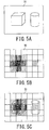
- Fig. 5 (which includes Figs. 5A to 5C ) is an explanation diagram explaining contents of overlaying processing step (step S3).
- Fig. 5A is an explanation diagram illustrating an example of the visible image 31
- Fig. 5B is an explanation diagram illustrating an example of the distribution image 32
- Fig. 5C is an explanation diagram illustrating an example of a displayed image 33 which is created (obtained) by overlapping the visible image 31 and the distribution image 32.
- the intensity display unit 15A creates image data of the displayed image 33 illustrated in Fig. 5C by overlaying the distribution image 32 (image of radiation intensity distribution) which is converted into two-dimensional static image and is illustrated in Fig. 5B on the visible image 31 illustrated in Fig. 5A .
- the image data of the displayed image 33 is provided to output (display) element, the displayed image 33 is displayed in the output element.
- the image data of the displayed image 33 can be acquired by performing overlay operation (calculation) of the distribution image 32 with respect to the visible image 31.
- the intensity display unit 15A converts two-dimensional arrangement of radiation intensity distribution into two-dimensional static image.
- the intensity display unit 15A expresses the radiation intensity distribution by using grayscale (monochrome).
- grayscale monoochrome
- the intensity display unit 15A displays radiation intensity by using color instead of monochrome, and can thereby expand range which user can recognize the radiation intensity in comparison with a case where grayscale is used.
- An example which allocates some colors to radiation intensity will be described hereunder ( Figs. 6 to 8 ).
- the intensity display unit 15A may display the visible image 31 as monochrome image, the distribution image 32 as color image. In this case, a visibility in the intensity display unit 15A can be improved without mutually interfering with the visible image 31 and the distribution image 32.
- the intensity display unit 15A may have a function of selecting one as image displayed in the intensity display unit 15A from the visible image 31, the distribution image 32, and the displayed image 33 (which is created by overlaying the distribution image 32 on the visible image 31).
- Fig. 6 (which includes Figs. 6A and 6B), Fig. 7 (which includes Figs. 7A and 7B), and Fig. 8 (which includes Figs. 8A and 8B ) are explanations diagram explaining allocation of colors with respect to radiation intensity distribution performed by the intensity display unit 15A.
- Figs. 6A, 7A, and 8A are the explanation diagram illustrating the radiation intensity distribution in x axis direction.
- Fig. 6B is the explanation diagram illustrating color allocation of the radiation intensity distribution, based on a maximum value of radiation intensity.
- Fig. 7B is the explanation diagram illustrating color allocation of the radiation intensity distribution, based on a user maximum value 43 set by user.
- Fig. 8B is the explanation diagram illustrating color allocation of the radiation intensity distribution, based on an average value of radiation intensity.
- the intensity display unit 15A extracts the maximum value 41 from the radiation intensity distribution and decides color allocation (coloration) 42 to the radiation intensity ( Fig. 6B ) based on the maximum value 41 extracted by the intensity display unit 15A.
- the intensity display unit 15A allocates black as first color representing strongest radiation intensity to maximum value 41, and white to radiation intensity being zero. In case of using color, the intensity display unit 15A allocates red to maximum value 41, and blue to radiation intensity being zero.
- the intensity display unit 15A may use a value 43 (which will be hereinafter referred to as "user maximum value”) which is arbitrarily set by user as maximum value of radiation intensity for allocating colors to radiation intensity instead of maximum value 41, and decide color allocation to the radiation intensity ( Fig. 7B ) based on the user maximum value 43.
- user maximum value a value 43 (which will be hereinafter referred to as "user maximum value" which is arbitrarily set by user as maximum value of radiation intensity for allocating colors to radiation intensity instead of maximum value 41, and decide color allocation to the radiation intensity ( Fig. 7B ) based on the user maximum value 43.
- the intensity display unit 15A decides color allocation 44 to the radiation intensity ( Fig. 7B ) based on the user maximum value 43. For example, the intensity display unit 15A allocates black representing radiation intensity being stronger than radiation intensity of which value is equal to the user maximum value 43, and evenly allocates other colors to radiation intensity of which value is larger than zero.
- the intensity display unit 15A may use an average value ( Fig. 8B ) of radiation intensity for allocating colors to radiation intensity instead of maximum value 41 ( Fig. 6B ) or user maximum value 43 ( Fig. 7B ).
- the intensity display unit 15A calculates the average value " ⁇ " of the radiation intensity.
- the intensity display unit 15A uses the average value " ⁇ " as a threshold value 45 for displaying the radiation intensity, and decides color allocation (coloration) 46 with respect to a cell representing radiation intensity of which value is equal to and less than the threshold value 45 so as not to display the cell representing radiation intensity of which value is equal to and less than the threshold value 45 in the intensity display unit 15A. That is, the radiation intensity which is not larger than the threshold value 45 is not considered when the distribution image 32 is created.
- a value being predetermined percentage of maximum value may be used as the threshold value 45.
- a value being predetermined percentage of maximum value may be used as the threshold value 45.
- the threshold value 45 may be arbitrarily set by user.
- Fig. 9 is a timeline explaining a first timing example in a case where processing steps (steps S1 to S4) of the first radiation measurement procedure are performed.
- An acquisition rate 51 (image acquisition rate 51) of visible image in the visible image acquisition step (step S1) and an acquisition rate 52 (intensity acquisition rate 52) of the radiation intensity distribution in the radiation intensity acquisition step (step S2) can arbitrarily be set by user.
- the image acquisition rate 51 can be set so as not to be less than a necessary time 53 (image necessary acquisition time 53) for acquiring the visible image in the visible image acquisition step (step S1)
- the intensity acquisition rate 52 can be set so as not to be less than a necessary time 54 (intensity necessary acquisition time 54) for acquiring the radiation intensity distribution.
- the overlay processing step (step S3) and the data storing step (step S4) are performed in accordance with the image acquisition rate 51 being larger one of the image acquisition rate 51 and the intensity acquisition rate 52.
- the image necessity acquisition time 53 is shorter than the intensity necessity acquisition time 54. Accordingly, if the step S4 is performed in synchronization with the image acquisition rate 51, information of radiation intensity is redundantly stored in the data storage unit 16. As a result, redundant storing operation causes storage capacity of the data storage unit 16 to be increased. In this case, it is preferable that the step S4 is performed with a timing illustrated in Fig. 10 which is described hereunder.
- Fig. 10 is a timeline explaining a second timing example in a case where processing steps (steps S1 to S4) of the first radiation measurement procedure are performed.
- the visible image acquisition step (step S1) is performed in synchronization with a time when the radiation intensity acquisition step (step S2) is started. Further, when the radiation intensity acquisition step is completed, the overlay processing step (step S3) and the data storing step (step S4) are simultaneously started and performed.
- step S1 to S4 in the first radiation measurement procedure is performed with the second timing as above-described, used amount of storage capacity in the data storage unit 16 can keep to a necessary minimum amount.
- the overlay processing step (step S3) may be performed in synchronization with the image acquisition rate 51
- the data storing step (step S4) may be performed in synchronization with the intensity acquisition rate 52.
- Fig. 11 is a timeline explaining a third timing example in a case where processing steps (steps S1 to S4) of the first radiation measurement procedure are performed.
- the visible image acquisition step (step S1b) is performed in synchronization with a time when the radiation intensity acquisition step (step S2b) is started. Therefore, the radiation measurement apparatus 10A can display with overlaying the radiation intensity on the visible image of which the acquirement start time is synchronized with the acquirement start time of the radiation intensity.
- the radiation measurement apparatus 10A can display the displayed image 33 acquired by overlaying the distribution image 32 of the radiation intensity on the visible image 31 being acquired simultaneously with the distribution image 32. Therefore, the radiation measurement apparatus 10A relates user's real field of view to the radiation intensity, and thereby enables user to intuitively recognize incoming direction of radiation which has high radiation intensity.
- the radiation measurement apparatus 10A accurately relates the view angle of the visible image acquisition unit 11 that acquires the visible images to the view angle of the radiation intensity acquisition unit 12 that acquires the radiation intensity, and accurately synchronizes the acquisition timing of each of data. Therefore, the radiation measurement apparatus 10A can provide user with accurate radiation intensity information.
- the radiation measurement apparatus 10A holds data obtained by performing radiation measurement together with the time information and the position information, trace of obtained data can be easy. Therefore the radiation measurement apparatus 10A can improve a traceability of obtained data.
- the radiation measurement apparatus 10A measures radiation intensity with displaying measurement result on own display unit, and thereby enables user to intuitively determine whether a place where user works is safe for user or not.
- the radiation measurement apparatus 10A makes it easy to manage safe of operator.
- the radiation measurement apparatus 10A makes it easy to visually determine that a direction and/or a member, of irradiating a radiation of which radiation dose is high, and can thereby make it easy for user to built effective shield.
- the radiation measurement apparatus 10A is necessarily not limited to a configuration illustrated in Fig. 1 .
- the radiation measurement apparatus 10A may be configured by the radiation detector 2A that omits the position information acquisition unit 13 from the radiation detector 2A illustrated in Fig. 1 and the information processor 3A that omits the data storage unit 16, the data search unit 17, and the date-time management unit 18 from the information processor 3A illustrated in Fig. 1 .
- the radiation measurement apparatus 10A includes the radiation detector 2A that at least has the visible image acquisition unit 11 and the radiation intensity acquisition unit 12, and the information processor 3A that at least has the intensity display unit 15A, the radiation measurement apparatus 10A may arbitrarily be configured.
- the radiation measurement apparatus 10A may include the radiation detector 2A having a part or whole of the information processor 3A as a configuration example.
- the configuration example can be adopted in above-mentioned another embodiment or other examples as well as in the radiation measurement apparatus 10A.
- Fig. 13 is a configuration diagram of a radiation measurement apparatus 10B that is an example of a radiation measurement apparatus according to an embodiment of the invention.
- the radiation measurement apparatus 10B as the example of the radiation measurement apparatus is different from the radiation measurement apparatus 10A in that the radiation measurement apparatus 10B includes a radiation detector 2B and an information processor 3B instead of the radiation detector 2A and the information processor 3A. Meanwhile, the radiation measurement apparatus 10B is not substantially different from the radiation measurement apparatus 10A in the other points.
- the same reference numerals or characters in the radiation measurement apparatus 10B are assigned to the same or similar components and parts as those in the radiation measurement apparatus 10A, and the duplicated description thereof is omitted.
- the radiation detector 2B has the visible image acquisition unit 11, the radiation intensity acquisition unit 12, and an operation display unit 13.
- the visible image acquisition unit 11, the radiation intensity acquisition unit 12, and the operation display unit 13 are accommodated in a housing 5 together.
- the visible image acquisition unit 11 acquires a video signal, and then acquires static images (freeze-frames) by freezing the video signal.
- the static images are successively transmitted from the visible image acquisition unit 11 to a movement distance calculation unit 62. Further, the radiation intensity distribution acquired as a result of measurement performed by the radiation intensity acquisition unit 12 is successively transmitted to a resolution improvement unit 63.
- the radiation intensity acquisition unit 12 acquires the radiation intensity distribution 32 ( Fig. 5B ) which has lower resolution than resolution of the visible image 31 ( Fig. 5A ) acquired by the visible image acquisition unit 11.
- the detection elements are arranged in a state where the arrangement number of the detection elements is limited. As a result, it is often that the distribution image 32 can be acquired with a space resolution being lower than a space resolution of the visible image 31.
- the radiation detector 2 can make a cell of the radiation intensity distribution (image) 32 responsive to a coordinate on the visible image 31 as with the displayed image 33 ( Fig. 5C ). That is, the radiation detector 2 enables one (1) cell of the distribution image 32 to correspond to N ⁇ N (N> 1) pixels of the visible image 31.
- the operation display unit 61 (operational state inform unit) monitors an operational state of the radiation intensity acquisition unit 12, displays the operational state, and thereby provides user with the operational state.
- the operation display unit 61 may inform user by sound notifying user of operational state instead of indication.
- the information processor 3B is, for example, personal computer.
- the information processor 3B has an intensity display unit 15B, the movement distance calculation unit 62, the resolution improvement unit 63, the data storage unit 16, and a movement alarm unit 64.
- the information processor 3B further has an input unit that and an output unit that provides user with information such as processing result.
- the intensity display unit 15B is different from the intensity display unit 15A that allocates a plurality of colors to the radiation intensity acquired by the radiation intensity acquisition unit 12, and thereby expresses the radiation intensity by using allocated colors in that the intensity display unit 15B further having a function that allocates a plurality of colors to the radiation intensity distribution (high resolution intensity distribution) of which resolution is improved by the resolution improvement unit 63, and thereby expresses the radiation intensity by using allocated colors.
- the intensity display unit 15B is configured as the same conditions as the intensity display unit 15A except of further having the resolution improvement function.
- the intensity display unit 15B can be acquired by performing overlay operation (calculation) of an image of the high resolution intensity distribution, and express the high resolution intensity distribution (image) by using grayscale or color (RGB) image in accordance with radiation intensity value.
- the intensity display unit 15B can express the high resolution intensity distribution (image) by using grayscale or color (RGB) image, and thereby provides user with the high resolution intensity distribution having higher resolution than original (the distribution image 32) together with the visible image in a state where the high resolution intensity distribution has good visibility.
- the movement distance calculation unit 62 calculates a movement distance (movement quantity) between visible images that are successively acquired by the visible image acquisition unit 11.
- the resolution improvement unit 63 acquires the radiation intensity distribution (image) (which will be hereinafter referred to as "high resolution intensity distribution") having higher resolution than original (the distribution image 32) by moving (shifting) one of the radiation intensity distributions that is nearly simultaneously acquired with the visible images the movement distance (movement quantity) calculated by the movement distance calculation unit 62 and overlaying one radiation intensity distribution on the other radiation intensity distribution.
- the data storage unit 16 stores the visible images and the radiation intensity distributions therein together with the movement distance during single-measurement performed by the radiation intensity acquisition unit 12.
- the movement alarm unit 64 determines whether the movement distance calculated by the movement distance calculation unit 62 when the radiation intensity acquisition unit 12 measures the radiation intensity, exceeds threshold value which is a maximum movement distance in a range where the resolution improvement unit 63 can acquire the high resolution intensity distribution. If the movement alarm unit 64 determines the movement distance is larger than the threshold value, the movement alarm unit 64 provides user with warning. In order to provide user with warning, for example, the information processor 3B displays result determined by the movement alarm unit 64 together with measurement result of the radiation intensity distribution in display means such as own display unit, or outputs sound such as an alarm. Next, operations of the radiation measurement apparatus 10B will be described.
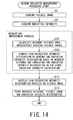
- Fig. 14 is a flowchart explaining processing steps (steps S1, S2, S11, S12, S3, and S4) of a second radiation measurement procedure performed by the radiation measurement apparatus 10B.
- the second radiation measurement procedure is different from the first radiation measurement procedure in that the second radiation measurement procedure further includes steps (steps S11 and S12) as to a resolution improvement process that improves resolution of the radiation intensity distribution, the radiation intensity distribution that becomes overlay object (which denotes object to be overlaid before the overlay processing step is performed or overlaid object after the overlay processing step is performed), and data that becomes storage object (which denotes object to be stored before the data storing step is performed and stored object after the data storing step is performed). Meanwhile, the second radiation measurement procedure is not substantially different from the first radiation measurement procedure in the other points. Thus, in description of the second radiation measurement procedure, the same step number in the second radiation measurement procedure are assigned to the same or similar steps as those in the first radiation measurement procedure, and the duplicated description thereof is omitted.
- the second radiation measurement procedure includes the visible image acquisition step (step S1), the radiation intensity acquisition step (step S2), the resolution improvement process (steps S11 and S12) having a movement distance calculation step (step S11) and a high resolution intensity distribution acquisition step (step S12), an overlay processing step (step S13), and a data storing step (step S14).
- the steps S1 and S2 is performed.
- the visible image acquisition unit 11 acquires the visible images in the step S1.
- the radiation intensity acquisition unit 12 acquires radiation intensity distributions in the step S2.
- the visible images acquired by the visible image acquisition unit 11 are transmitted to the intensity display unit 15B.
- the radiation intensity distributions acquired by the radiation intensity acquisition unit 12 are transmitted to the resolution improvement unit 63.
- step S11 the movement distance calculation step in the resolution improvement process is performed.
- the movement distance calculation unit 62 successively calculates the movement distance of the radiation detector 2B (the visible image acquisition unit 11).
- the high resolution intensity distribution acquisition step step S12.
- plural radiation intensity distributions being acquired nearly simultaneously with the visible images used in the movement distance calculation step (step S11) are overlaid by the resolution improvement unit 63 with a situation where the movement distance calculated in the step S11 is shifted, thereby being acquired the high resolution intensity distribution.
- the overlay processing step (step S13) is performed.
- the intensity display unit 15B creates (obtains) display data (image data for display) by overlaying the high resolution intensity distribution acquired in the step S12 on the visible image acquired in the step S1, and transmits the image data to the output unit. Then, in the display as the output unit, a display (an indication) based on the display data transmitted to the output unit. That is, the high resolution intensity distribution is displayed with a situation where the high resolution intensity distribution is overlaid on the visible image in the output unit.
- step S14 the data storage unit 16 stores the visible images and the radiation intensity distributions therein together with the movement distance during single-measurement performed by the radiation intensity acquisition unit 12.
- step S14 all processing steps of the second radiation measurement procedure are completed, hence the second radiation measurement procedure is finished (END).
- Fig. 15 is an explanation diagram of two visible images 31a and 31b successively acquired in the radiation detector 2B.
- Fig. 16 is an explanation diagram explaining a case where the movement distance calculation unit 62 calculates from two visible images 31a and 31b successively acquired in the radiation detector 2B.
- the movement distance calculation unit 62 sets at least one comparison region 72 to compare the visible image 31a with the visible image 31b on the visible image 31a.
- the movement distance calculation unit 62 scans the comparison region 72 with respect to the visible image 31b in a direction of arrow L illustrated in Fig. 16 with each completion of one-pixel shift.
- the movement distance calculation unit 62 performs a matching process which calculates a correlative value of brightness in each position of the comparison region 72.
- the movement distance calculation unit 62 calculates a gap quantity between the visible images 31a and 31b when the brightness correlation value becomes maximum value in the matching process, as movement distance.
- Fig. 17 is an explanation diagram explaining positional relation of two visible images 31a and 31b when correlation value becomes maximum value.
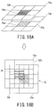
- Fig. 18 (which includes Figs. 18A and 18B ) is an explanation diagram explaining a case where radiation intensity distribution (high resolution intensity distribution) 75 having twice as high resolution as resolution of original radiation intensity distribution is created.
- Fig. 18A is an explanation diagram explaining a state before two radiation intensity distributions 73a and 73b are overlapped.
- Fig. 18B is an explanation diagram explaining a state after two radiation intensity distributions 73a and 73b are overlapped.
- the movement distance calculation unit 62 calculates a gap quantity x1 ( Fig. 17 ) as movement distance in x axis direction and a gap quantity y1 ( Fig. 17 ) as movement distance in y axis direction.
- a unit of the gap is the number of pixels (pixel number).
- the resolution improvement unit 63 overlaps a plurality of (two) radiation intensity distributions which are acquired nearly simultaneously with the visible images 31 (31a and 31b) used in a case where the movement distance calculation unit 62 calculates the movement distance, and thereby acquires the high resolution intensity distribution 75.
- the resolution improvement unit 63 uses the movement distance calculated by the movement distance calculation unit 62, i.e., the gap quantities x1 and y1, and thereby overlays one of two (plural) radiation intensity distributions on the other of them.
- the resolution improvement unit 63 can shift the radiation intensity distribution by a unit being smaller than one cell of the radiation intensity distribution, i.e., pixel unit of the visible image by using space resolution differences between the visible image and the radiation intensity distribution, and can then overlay one radiation intensity distribution on a radiation intensity distribution other than the one radiation intensity distribution, the resolution improvement unit 63 creates the radiation intensity distribution (which will be hereinafter referred to as "high resolution intensity distribution") 75 which is expressed by a cell (which will be hereinafter referred to as "high resolution cell”) 76 being smaller than the original cell of the radiation intensity distribution.
- high resolution intensity distribution which is expressed by a cell (which will be hereinafter referred to as "high resolution cell"
- the high resolution cell 76 in the high resolution intensity distribution 75 of which space resolution is improved has two intensity values of the original cells 74a and 74b.
- the resolution improvement unit 63 calculates, for example, average intensity (average value of intensity) of two original cells 74a and 74b, whereby the intensity value of the high resolution cell 76 can be most easily specified (calculated). Needless to say, the resolution improvement unit 63 may decide the intensity value of the high resolution cell 76 having plural intensity values by other ways than the way of calculating average of the intensity values of the original cells 74a and 74b.
- the radiation intensity acquisition unit 12 measures radiation by waiting radiation incoming from measurement direction a predetermined time and then counting quantity of incoming radiation. Therefore, if a direction to which the radiation intensity acquisition unit 12 faces is changed on the radiation measurement, the radiation intensity acquisition unit 12 cannot precisely count quantity of incoming radiation from the same direction. Therefore, the radiation intensity distribution acquired by measuring radiation while user takes the radiation detector 2B significantly decreases reliability thereof. Further, even if the radiation intensity distribution of which reliability is significantly decreased is input to the resolution improvement unit 63, the resolution cannot be normally improved.
- Fig. 19 is a timeline explaining a timing example when processing steps (steps S1 and S2) of the second radiation measurement procedure performed by the radiation measurement apparatus according to second embodiment are performed.
- the intensity necessity acquisition time 54 that is the necessary time in a case where the radiation intensity acquisition unit 12 acquires the radiation intensity distribution is longer than the image necessity acquisition time 53 that is the necessary time in a case where the visible image acquisition unit 11 acquires the visible image.
- the visible image acquisition unit 11 needs the image necessary acquisition time 53 for the sake of acquiring the visible image at the image acquisition rate 51.
- the image necessary acquisition time 53 corresponds to exposure time.
- the radiation intensity acquisition unit 12 acquires radiation intensity in the intensity acquisition rate 52, and therefore needs the intensity necessity acquisition time 54. That is, the intensity acquisition rate 52 and the intensity necessity acquisition time 54, in the step S2 is longer than the image acquisition rate 51 and the image necessary acquisition time 53, in the step S1.
- times excluding the necessary acquisition times 53 and 54 in the acquisition rates 51 and 52 corresponds to data transfer time. That is, since the radiation intensity acquisition unit 12, there is no problem with moving the radiation detector 2B on the data transfer time.
- the operation display unit 61 monitors the operational state of the radiation intensity acquisition unit 12 and displays the operational state for user. For example, the operation display unit 61 displays a message such as "now measuring” or “now data transferring” in the radiation detector 2B, or the message together with the visible image and the radiation intensity distribution in the display unit of the information processer 3B.
- the radiation measurement apparatus 10B can prevent unnecessary movement, and therefore acquire the radiation intensity distribution with better accuracy.
- the movement alarm unit 64 outputs the alarm to user, and thereby notifies user whether there is data reliability or not.
- the movement distance calculation unit 62 successively calculates the movement distance in measuring radiation intensity in synchronization with the image acquisition rate 51 by using a difference between the image acquisition rate 51 and the intensity acquisition rate 52.
- the movement alarm unit 64 acquires the movement distance calculated by the movement distance calculation unit 62 from the movement distance calculation unit 62.
- the movement alarm unit 64 monitors whether the movement distance acquired by the movement distance calculation unit 62 exceeds the than the threshold value.
- the movement alarm unit 64 may be configured to enable user to arbitrarily set the threshold value.
- As general threshold value if N is the pixel number of the visible image corresponding to one cell of the radiation intensity distribution, the threshold value is preferable to be less than N/2.
- the movement alarm unit 64 In a case where the movement distance being larger (longer) than the threshold value is detected, the movement alarm unit 64 outputs an alarm notifying user a situation where the movement distance of the radiation intensity acquisition unit 12 (the radiation measurement apparatus 10B) exceeds than the threshold value.
- the movement alarm unit 64 allows the information processer 3B to display the alarm together with the visible image and the radiation intensity distribution in own display unit, or to output alarm sound. While user can check whether the radiation intensity distribution currently acquired by the radiation intensity acquisition unit 12 is reliable by only checking whether there is the alarm or not, user can perform the measurement operation.
- the movement alarm unit 64 enables the resolution improvement unit 63 to only collect the radiation intensity distribution acquired when the movement distance does not exceed the threshold value, by excluding the radiation intensity distribution acquired when the movement distance of the radiation intensity acquisition unit 12 exceeds the threshold value as well as to notify user the situation where the movement distance of the radiation intensity acquisition unit 12 (the radiation measurement apparatus 10B) exceeds than the threshold value. That is, the resolution improvement unit 63 acquires the high resolution intensity distribution by using the radiation intensity distribution acquired when the movement distance does not exceed the threshold value. Meanwhile, the resolution improvement unit 63 does not acquire the high resolution intensity distribution when the movement distance exceeds the threshold value.
- the radiation measurement apparatus 10B only use accurate radiation intensity distribution, and can thereby improve the space resolution of the radiation intensity distribution.
- user can measure radiation intensity without paying attention to an effect on measurement accuracy caused by moving the radiation measurement apparatus 10B.
- the radiation measurement apparatus 10B includes the movement alarm unit 64, and therefore use the movement distance as an index showing liability of radiation intensity distribution measured by the radiation measurement apparatus 10B.
- the radiation measurement apparatus 10B can improve the space resolution of the radiation intensity distribution without increasing the arrangement number of radiation detectors, and thereby acquire the radiation intensity distribution with better accuracy without losing portability. Therefore, the radiation measurement apparatus 10B can improve resolution as well as portability.
- the radiation measurement apparatus 10B can acquire the radiation intensity distribution that is preferable to improve the space resolution of the radiation intensity distribution by using the movement distance of the radiation measurement apparatus 10B (the visible image acquisition unit 11 and the radiation intensity acquisition unit 12) as an index.
- the radiation measurement apparatus 10B can preferably notice user of the reliability of the radiation intensity distribution as measurement result.
- the radiation measurement apparatus 10B can quantify the reliability of the radiation intensity distribution by using the movement distance. Since the radiation measurement apparatus 10B stores the visible images and the radiation intensity distribution together with the movement distance, the radiation measurement apparatus 10B enables user to select the radiation intensity distribution that is preferable to improve the space resolution by using the index even if the radiation measurement has completed. Therefore, the radiation measurement apparatus 10B can anew improve the space resolution of the radiation intensity distribution even if the radiation measurement has completed.
- the radiation measurement apparatus 10B described above is merely an example of the radiation measurement apparatus according to second embodiment. Therefore, it is not necessarily limited to configuration illustrated in the accompanying drawings such as Fig. 13 .
- Figs. 20 and 21 are configuration diagrams of the radiation measurement apparatus 10B as the other examples of the radiation measurement apparatus.
- the radiation measurement apparatus 10B may the radiation detector 2B that is configured by omitting the operation display unit 61 from the radiation detector 2B of the radiation measurement apparatus 10B illustrated in Fig. 13 , and the information processer 3B that is configured by omitting the data storage unit 16 and the movement alarm unit 64 from the information processer 3B of the radiation measurement apparatus 10B illustrated in Fig. 13 .
- the radiation measurement apparatus 10B includes the radiation detector 2B at least having the visible image acquisition unit 11 and the radiation intensity acquisition unit 12 and the information processer 3B at least having the movement distance calculation unit 62 and the resolution improvement unit 63, the radiation measurement apparatus 10B can arbitrarily be configured.
- the radiation measurement apparatus 10B above-described is an example where FOV of acquired visible image (and radiation intensity) is changed by using so-called camera shake caused by user.
- the radiation measurement apparatus 10B may include the radiation detector 2B being provided with a moving device 80 that is configured to intently move the radiation measurement apparatus 10B a predetermined distance.
- the radiation measurement apparatuses 10A and 10B, and the methods by using the radiation measurement apparatuses 10A and 10B enables user to intuitively recognize measurement result of radiation. Further, the radiation measurement apparatuses 10A and 10B, and the methods by using the radiation measurement apparatuses 10A and 10B can improve space resolution as well as portability.
- a manner described in each embodiment is written in a memory medium such as a magnetic disk, an optical disk, a semiconductor memory, or the like, or transmitted through transmission medium as a computer readable program.
- the computer readable program can be applied to various devices.
- a computer which realizes the apparatus reads out program held in the memory medium, thereby controls operation, and performs above-mentioned procedures.
- Figs. 22 and 23 are configuration diagrams of other examples of the radiation measurement apparatus according to the embodiments.
- the radiation measurement apparatus 10C that includes the radiation detector 2C having the visible image acquisition unit 11 and the radiation intensity acquisition unit 12, and the information processor 3C having the intensity display unit 15B, the movement distance calculation unit 62, and the resolution improvement unit 63 may be configured as the radiation measurement apparatus according to one embodiment.
- the radiation measurement apparatus 10D that includes the radiation detector 2D having the visible image acquisition unit 11, the radiation intensity acquisition unit 12, the position information acquisition unit 13, and the operation display unit 61, and the information processor 3D having the intensity display unit 15B, the movement distance calculation unit 62, the resolution improvement unit 63, the data storage unit 16, the data search unit 17, the movement alarm unit 64 may be configured as the radiation measurement apparatus according to one embodiment.
Description
- The present invention relates to a radiation measurement apparatus that measures an intensity distribution of radiation.
- It is important for operators working in a nuclear electricity generation plant or citizens living in a neighborhood of the nuclear electricity generation plant to reduce radiation exposure. Further, in a case where user wants to determine a position of radiation source in some place such as operation site, it is required that a radiation measurement apparatus that has a high portability or enables user to take it anywhere. Conventionally, radiation measurement technology disclosed in
patent document 1 has known as an example of radiation measurement technology. - The radiation measurement technology disclosed in
patent document 1 includes a radiation detector that is arranged in two-dimensional arrangement such as a matrix or the like and a collimator that arranges in front of the radiation detector and limits incoming direction of radiation, and visualizes radiation intensity as two dimensional distribution. - Patent Document 1: Publication of (Unexamined) Japanese Patent Application No.
2005-49136 - Patent document
WO03/046611 line 25 to p.16, line 2). Patent documentJP2008188164 - If conventional radiation measurement technology is used, radiation intensity distribution which has certain view angle with respect to facing direction of radiation measurement apparatus can be acquired at one time. Accordingly, conventional radiation measurement technology reduces workload in measurement operation.
- However, in the site where many structures are provided to an apparatus, such as the nuclear power plant, when user merely observes two-dimensional (2D) radiation distribution, it is difficult for the user to determine and intuitively understand desired information such as members being radiation source and/or incoming direction of radiation.
- Further, if user uses the radiation measurement apparatus at site where many structures are provided to an apparatus, such as the nuclear power plant, it is important that the radiation measurement apparatus has a high portability or enables user to easily take it anywhere as well as that the radiation measurement apparatus can measure radiation with better precision.
- Here, there is an idea which improves space resolution of radiation intensity distribution as an example of idea further increasing measurement accuracy of radiation. If space resolution of radiation intensity distribution is improved, it is required to increase the arrangement number of radiation detectors.
- However, if the arrangement number of radiation detectors is merely increased, housing size of the radiation measurement apparatus gets larger. If carries the radiation measurement apparatus and uses it while user moves, since portability of the radiation measurement apparatus should be considered, it is required that the housing size fits within required size. As described above, since relation between portability and space resolution is incompatible (trade-off), there is a problem in that it become difficult to acquire radiation intensity distribution which has high resolution if the housing size is limited.
- The present invention has been made in consideration of the circumstances mentioned above, and an object thereof is to provide a radiation measurement apparatus that enables user to intuitively recognize a radiation measurement result. Further, the object of the present invention is to provide a radiation measurement apparatus that can improve resolution as well as portability.
- In order to solve the problem in the conventional art mentioned above, the present invention provides a radiation measurement apparatus according to
claim 1. - According to the present invention, user can intuitively recognize a radiation measurement result. Further, the present invention can improve resolution as well as portability.
-
- [
Fig. 1 ] is a configuration diagram of a radiation measurement apparatus. - [
Fig. 2 ] is a configuration diagram of first example of a visible image acquisition unit and a radiation intensity acquisition unit, in a radiation detector included in the radiation measurement apparatus. - [
Fig. 3 ] is a configuration diagram of second example of a visible image acquisition unit and a radiation intensity acquisition unit, in a radiation detector included in the radiation measurement apparatus. - [
Fig. 4 ] is a flowchart explaining processing steps of a first radiation measurement procedure performed by the radiation measurement apparatus. - [
Fig. 5 ] (which includesFigs. 5A, 5B, and 5C ) is an explanation diagram explaining contents of overlay processing in a first radiation measurement procedure performed by the radiation measurement apparatus.Fig. 5A is an explanation diagram illustrating an example of a visible image,Fig. 5B is an explanation diagram illustrating an example of a distribution image, andFig. 5C is an explanation diagram illustrating an example of displayed image which is acquired by overlaying the distribution image on the visible image. - [
Fig. 6 ] (which includesFigs. 6A and 6B ) is an explanation diagram explaining allocation of colors with respect to radiation intensity distribution performed by a intensity display unit of the radiation measurement apparatus.Fig. 6A is an explanation diagram illustrating a radiation intensity distribution in x axis direction, andFig. 6B is an explanation diagram illustrating color allocation of the radiation intensity distribution, based on a maximum value of radiation intensity. - [
Fig. 7 ] (which includesFigs. 7A and 7B ) is an explanation diagram explaining allocation of colors with respect to radiation intensity distribution performed by a intensity display unit of the radiation measurement apparatus.Fig. 7A is an explanation diagram illustrating a radiation intensity distribution in x axis direction, andFig. 7B is an explanation diagram illustrating color allocation of the radiation intensity distribution, based on a user maximum value set by user. - [
Fig. 8 ] (which includesFigs. 8A and 8B ) is an explanation diagram explaining allocation of colors with respect to radiation intensity distribution performed by a intensity display unit of the radiation measurement apparatus.Fig. 8A is an explanation diagram illustrating a radiation intensity distribution in x axis direction, andFig. 8B is an explanation diagram illustrating color allocation of the radiation intensity distribution, based on an average value of radiation intensity. - [
Fig. 9 ] is a timeline explaining a first timing example when processing steps (steps S1 to S4) of the first radiation measurement procedure are performed by the measurement apparatus. - [
Fig. 10 ] is a timeline explaining a second timing example when processing steps (steps S1 to S4) of the first radiation measurement procedure are performed by the measurement apparatus. - [
Fig. 11 ] is a timeline explaining a third timing example when processing steps (steps S1 to S4) of the first radiation measurement procedure are performed by the measurement apparatus. - [
Fig. 12 ] is a configuration diagram of another example of the radiation measurement apparatus. - [
Fig. 13 ] is a configuration diagram of a radiation measurement apparatus according to an embodiment of the invention. - [
Fig. 14 ] is a flowchart explaining processing steps of a second radiation measurement procedure performed by the radiation measurement apparatus. - [
Fig. 15 ] is an explanation diagram of two visible images successively acquired in the radiation detector included in the radiation measurement apparatus. - [
Fig. 16 ] is an explanation diagram explaining movement distance calculated from two visible images successively acquired in the radiation detector included in the radiation measurement apparatus according to the embodiment. - [
Fig. 17 ] is an explanation diagram explaining positional relation of two visible images when correlation value becomes maximum value in the radiation measurement apparatus. - [
Fig. 18 ] (which includesFigs. 18A and 18B ) is an explanation diagram explaining a case where radiation intensity distribution (high resolution intensity distribution) having twice as high resolution as resolution of original radiation intensity distribution is created.Fig. 18A is an explanation diagram explaining a state before two radiation intensity distributions are overlapped.Fig. 18B is an explanation diagram explaining a state after two radiation intensity distributions are overlapped. - [
Fig. 19 ] is a timeline explaining a timing example when processing steps (steps S1 and S2) of the second radiation measurement procedure performed by the radiation measurement apparatus are performed. - [
Fig. 20 ] is a circuit configuration diagram of another example of a radiation measurement apparatus. - [
Fig. 21 ] is a circuit configuration diagram of still another example of a radiation measurement apparatus. - [
Fig. 22 ] is a circuit configuration diagram of another example of a radiation measurement apparatus. - [
Fig. 23 ] is a circuit configuration diagram of still another example of the radiation measurement apparatus. - Hereunder, embodiments of the present invention will be described with reference to the accompanying drawings.
-
Fig. 1 is a configuration diagram of aradiation measurement apparatus 10A that is an example of a radiation measurement apparatus. - The
radiation measurement apparatus 10A (Fig. 1 ) includes aradiation detector 2A and aninformation processor 3A. Theradiation detector 2A and theinformation processor 3A are connected so as to be capable of transmitting information each other. - For example, the
radiation detector 2A has a visibleimage acquisition unit 11, a radiationintensity acquisition unit 12, and a positioninformation acquisition unit 13. For example, the visibleimage acquisition unit 11, the radiationintensity acquisition unit 12, and the positioninformation acquisition unit 13 are accommodated in ahousing 5 together. - The visible
image acquisition unit 11 is, for example, a camera including imaging element such as CCD (Charged Couple Device) or CMOS (Complementary Metal Oxide Semiconductor), and acquires one or more visible images. The one or more visible images acquired by the visibleimage acquisition unit 11 are transmitted to theinformation processor 3A. - The radiation
intensity acquisition unit 12 measures a radiation intensity distribution on 2D (two-dimensional) plane. The radiationintensity acquisition unit 12 includes a collimator, a plurality of detection elements (detector group), and a signal substrate. The collimator and leads radiation to the detector group. In the detector group, for example, the detection elements are arranged on 2D plane or spherical surface in two-dimensional arrangement such as a matrix or the like. The detector group detect radiation such as gamma ray (y -ray). The signal substrate processes a detection signal output from the detector group. - The visible
image acquisition unit 11 and the radiationintensity acquisition unit 12 are respectively configured to be possible to acquire the visible image and the radiation intensity distribution from same direction. A unit configuration of theunits Figs. 2 and3 ). - The position
information acquisition unit 13 includes means for being possible to measure current position, such as GPS (Global Positioning System), and acquires position information of the radiation detector 2 (the visibleimage acquisition unit 11 and the radiation intensity acquisition unit 12). - The
information processor 3A is, for example, personal computer. Theinformation processor 3A has anintensity display unit 15A, adata storage unit 16, adata search unit 17, and a date-time management unit 18. Theinformation processor 3A further has an input unit that and an output unit that provides user with information such as processing result. Here, for example, the output unit has at least one unit selected from a display unit that visually outputs information, a sound output unit that soundly outputs information, and a print unit that outputs information as characters. - The
intensity display unit 15A allocates a plurality of colors to the radiation intensity acquired by the radiationintensity acquisition unit 12, and thereby expresses the radiation intensity by using allocated colors. Theintensity display unit 15A displays the radiation intensity distribution that is expressed by using allocated colors and overlaid on the visible image. Theintensity display unit 15A expresses the radiation intensity (image) by using grayscale or color (RGB) image. - When grayscale image is used for expressing the radiation intensity, the
intensity display unit 15A, for example, allocates black to maximum radiation intensity and white to minimum (zero) radiation intensity, and thereby expresses the radiation intensity by using black, white, and halftone between black and white in accordance with radiation intensity value. When color image is used for expressing radiation intensity, for example, theintensity display unit 15A allocates red (R) to maximum radiation intensity, green (G) to middle radiation intensity, and blue (B) to minimum radiation intensity, and expresses radiation intensity by using red (R), green (G), blue (B), half color between red (R) and green (G), and half color between green (G) and blue (B) in accordance with radiation intensity value. - The
data storage unit 16 stores various kinds of data such as visible images acquired by the visibleimage acquisition unit 11 or radiation intensity distribution acquired by the radiationintensity acquisition unit 12. - Further, the visible images and the radiation intensity distributions are stored in the
data storage unit 16 together with information which can be search key such as date-time (date and time) information acquired from the date-time management unit 18 holding information (which will be hereinafter referred to as "date-time information") of current date-time or position information of theradiation detector 2, acquired by the positioninformation acquisition unit 13. It is noted that thedata storage unit 16 may be set so as to store the visible images and the radiation intensity distributions in predetermined storage together with either time information or position information. - The
data search unit 17 extracts data stored in thedata storage unit 16 on the basis of search key such as the date-time information, being input by user, and provides user with extracted data. - The
data search unit 17 may be configured to extract data of which time is the closest time from time obtained by user, and display extracted data if there is not data of which time information is completely consistent with time information input by user. - The
data search unit 17 may receive time information for predetermined period as search key (search condition) being input by user. In case, thedata search unit 17 extracts the visible image and the radiation intensity distribution acquired on the time representing time information in sequence, and successively displays extracted visible image and extracted radiation intensity distribution. Intervals of displaying them may be arbitrarily set by user. - The date-
time management unit 18 has information of current date-time (date and time). If thedata storage unit 16 is set so as to store information together with date-time information in storage, as data storage setting thereof, the date-time management unit 18 transmits current date-time information to thedata storage unit 16. Incidentally, display means may be provided to theradiation detector 2A. The display means may be configured to display current date-time based on the current date-time information. - Here, configurations of the
acquisition units - Since the radiation measurement apparatus according to embodiments displays image acquired by overlaying the radiation intensity distribution on the view image so that user can intuitively recognize measurement result of radiation intensity, it is required to acquire the view image taken from a direction and the radiation intensity distribution acquired from a direction substantially being equal to the direction from which the view image is taken (picked up). Thus, the visible
image acquisition unit 11 and the radiationintensity acquisition unit 12 are configured as illustrated inFigs. 2 and3 described hereunder. -
Figs. 2 and3 are configuration diagrams of first and second examples of the visibleimage acquisition unit 11 and the radiationintensity acquisition unit 12, in a radiation detector 2 (2A to 2D) included in the radiation measurement apparatus. - Each of the visible
image acquisition unit 11 and the radiation intensity acquisition unit 12 (Fig. 2 ) as first configuration are respectively accommodated incommon housing 5, and are adjacently mounted as close as possible so that incoming direction of visible light is directed parallel to incoming direction of radiation. However, there is a gap between aview angle 22 of the visibleimage acquisition unit 11 and aview angle 23 of the radiationintensity acquisition unit 12. Therefore, in the visibleimage acquisition unit 11 and the radiationintensity acquisition unit 12, a calibration process is performed before a radiation measurement. - For example, a
predetermined size object 25 that includes apoint radiation source 24 which irradiates radiation having higher radiation intensity than peripheral environment is arranged within both view angles 22 and 23. The visibleimage acquisition unit 11 and the radiationintensity acquisition unit 12 sequentially acquire the visible images and the radiation intensity with reference to theobject 25. Theinformation processor 3A can accurately overlay radiation intensity distribution on visible image in accurate position based on position relation between both view angles 22 and 23 (the visibleimage acquisition unit 11 and the radiation intensity acquisition unit 12). - Further, the visible
image acquisition unit 11 and the radiation intensity acquisition unit 12 (Fig. 3 ) can acquire the visible images and the radiation intensity distributions in a direction substantially being equal to a direction from which the visible images are taken (picked up) even if an influence of a parallax is not considered. - The
radiation detector 2A (housing 5) has areflector 27 that passes through radiation and reflects a visible light on a line (line of sight 26) along incident direction of radiation with respect to the radiationintensity acquisition unit 12. The visibleimage acquisition unit 11 is mounted in a direction of reflecting the visible light. The radiation coming from a direction of line ofsight 26 passes through thereflector 27, and is thereby detected at the radiationintensity acquisition unit 12. Meanwhile, since the visible light is reflected by thereflector 27, an optical path of the visible light is changed. As a result, the visibleimage acquisition unit 11 acquires the visible image on the basis of the visible light reflected by thereflector 27. Next, operations of theradiation measurement apparatus 10A will be described. -
Fig. 4 is a flowchart explaining processing steps (steps S1 to S4) of first radiation measurement procedure performed by theradiation measurement apparatus 10A. Namely, timings (which are hereunder illustrated inFigs. 9, 10 , and11 ) when each of steps S1 to S4 is performed will be described hereunder. - The first radiation measurement procedure, for example, includes a visible image acquisition step (step S1), a radiation intensity acquisition step (step S2), an overlay processing step (step S3), and a data storing step (step S4).
- In the step S1, the visible
image acquisition unit 11 acquires the visible image of object to be measured at predetermined acquisition rate or arbitrary acquisition rate being set by user. The acquisition rate is set by user within a range being equal to and less than maximum acquisition rate. For example, since general video camera can acquire video (image) single having 30 frames per 1 second (30 frames/sec), the static image is acquired at acquisition rate being set within 30 frames/sec. The visibleimage acquisition unit 11 acquires visible images and transmits visible images acquired to theintensity display unit 15A. - Subsequently, in the step S2, the radiation
intensity acquisition unit 12 acquires radiation intensity distribution being expressed as two-dimensional arrangement at predetermined acquisition rate or arbitrary acquisition rate being set by user. The radiationintensity acquisition unit 12 transmits the radiation intensity distribution to theintensity display unit 15A. - Subsequently, in the step S3, the
intensity display unit 15A creates (obtains) display data (image data for display) by overlaying the radiation intensity distribution acquired in the step S2 on the visible image acquired in the step S1, and transmits the image data to display means as output unit. In the output unit, a display (an indication) based on the display data transmitted to the output unit is displayed. That is, the radiation intensity distribution is displayed with a situation where the radiation intensity distribution is overlaid on the visible image in the output unit. - The
intensity display unit 15A may display a display (an indication) representing a maximum value of the radiation intensity on the visible image of a place where the radiation intensity becomes the maximum value in the step S3. Display (Indication) representing maximum of the radiation intensity, such as a point, a figure, a literature, maximum value or the like can be used. - Subsequently, in the step S4, the
data storage unit 16 stores thevisible image 31 and the radiation intensity distribution (the distribution image 32) therein together with information such as a time and position information of each image data. Thedata storage unit 16 may store the displayedimage 33 therein. For example, the time and position information is used as file name based on time and position representing the time and position information. A time when acquisition step is started or completed is used as the time information. If format of each data stored in thedata storage unit 16 is JPEG format, the position information may be further written in EXIF (Exchangeable Image Format) and be thereby managed as image property. - The
data search unit 17 arbitrarily extracts various data stored in thedata storage unit 16 in the step S4 based on the time or position information. Since thedata storage unit 16 stores each of data together with the time or position information therein, it becomes easy for thedata search unit 17 to perform ex-post facto data search (extraction) from data stored in thedata storage unit 16. A storing timing of each various data will be described (Figs. 9, 10 , and11 ). - If the step S4 is completed, all processing steps of the first radiation measurement procedure are completed, hence the first radiation measurement procedure is finished (END).
- Namely, although the first radiation measurement procedure above-described includes the data storing step (step S4), the first radiation measurement procedure does not necessarily include the data storing step. For example, in case of performing the first radiation measurement procedure by using
radiation measurement apparatus 10A does not include thedata storage unit 16, the data storing step may be omitted. - Next, the overlay processing step (step S3) that overlays an image (which will be hereinafter referred to as "distribution image") 32 of the radiation intensity distribution on the
visible image 31 and will be described in detail. -
Fig. 5 (which includesFigs. 5A to 5C ) is an explanation diagram explaining contents of overlaying processing step (step S3).Fig. 5A is an explanation diagram illustrating an example of thevisible image 31,Fig. 5B is an explanation diagram illustrating an example of thedistribution image 32, andFig. 5C is an explanation diagram illustrating an example of a displayedimage 33 which is created (obtained) by overlapping thevisible image 31 and thedistribution image 32. - For example, the
intensity display unit 15A creates image data of the displayedimage 33 illustrated inFig. 5C by overlaying the distribution image 32 (image of radiation intensity distribution) which is converted into two-dimensional static image and is illustrated inFig. 5B on thevisible image 31 illustrated inFig. 5A . After the image data of the displayedimage 33 is provided to output (display) element, the displayedimage 33 is displayed in the output element. Incidentally, the image data of the displayedimage 33 can be acquired by performing overlay operation (calculation) of thedistribution image 32 with respect to thevisible image 31. - Further, for the sake of acquiring the
distribution image 32, theintensity display unit 15A converts two-dimensional arrangement of radiation intensity distribution into two-dimensional static image. - In an example illustrated in
Fig. 5B , theintensity display unit 15A expresses the radiation intensity distribution by using grayscale (monochrome). In the example illustrated inFig. 5B , if radiation intensity becomes weaker, display (indication) in accordance with radiation intensity becomes closer from white. Meanwhile, if radiation intensity becomes stronger, display (indication) in accordance with radiation intensity becomes closer from black. Theintensity display unit 15A displays radiation intensity by using color instead of monochrome, and can thereby expand range which user can recognize the radiation intensity in comparison with a case where grayscale is used. An example which allocates some colors to radiation intensity will be described hereunder (Figs. 6 to 8 ). - Further, the
intensity display unit 15A may display thevisible image 31 as monochrome image, thedistribution image 32 as color image. In this case, a visibility in theintensity display unit 15A can be improved without mutually interfering with thevisible image 31 and thedistribution image 32. - Furthermore, in case of displaying image displayed in the
intensity display unit 15A as display means, theintensity display unit 15A may have a function of selecting one as image displayed in theintensity display unit 15A from thevisible image 31, thedistribution image 32, and the displayed image 33 (which is created by overlaying thedistribution image 32 on the visible image 31). - Subsequently, a color assignment of radiation intensity distribution, performed by the
intensity display unit 15A will be described. For the sake of simplifying explanation, a description described hereunder explains a case where the radiation intensity distribution is one dimensional distribution as an example. -
Fig. 6 (which includesFigs. 6A and 6B), Fig. 7 (which includesFigs. 7A and 7B), and Fig. 8 (which includesFigs. 8A and 8B ) are explanations diagram explaining allocation of colors with respect to radiation intensity distribution performed by theintensity display unit 15A. - For detail,
Figs. 6A, 7A, and 8A are the explanation diagram illustrating the radiation intensity distribution in x axis direction.Fig. 6B is the explanation diagram illustrating color allocation of the radiation intensity distribution, based on a maximum value of radiation intensity.Fig. 7B is the explanation diagram illustrating color allocation of the radiation intensity distribution, based on a usermaximum value 43 set by user.Fig. 8B is the explanation diagram illustrating color allocation of the radiation intensity distribution, based on an average value of radiation intensity. - For example, if the radiation intensity distribution in a direction along x axis illustrated in
Fig. 6A is transmits to theintensity display unit 15A, theintensity display unit 15A extracts themaximum value 41 from the radiation intensity distribution and decides color allocation (coloration) 42 to the radiation intensity (Fig. 6B ) based on themaximum value 41 extracted by theintensity display unit 15A. - In case of using grayscale, the
intensity display unit 15A allocates black as first color representing strongest radiation intensity tomaximum value 41, and white to radiation intensity being zero. In case of using color, theintensity display unit 15A allocates red tomaximum value 41, and blue to radiation intensity being zero. - Further, the
intensity display unit 15A may use a value 43 (which will be hereinafter referred to as "user maximum value") which is arbitrarily set by user as maximum value of radiation intensity for allocating colors to radiation intensity instead ofmaximum value 41, and decide color allocation to the radiation intensity (Fig. 7B ) based on the usermaximum value 43. - For example, if the radiation intensity distribution in a direction along x axis illustrated in
Fig. 7A is transmits to theintensity display unit 15A and the usermaximum value 43 is set, theintensity display unit 15A decidescolor allocation 44 to the radiation intensity (Fig. 7B ) based on the usermaximum value 43. For example, theintensity display unit 15A allocates black representing radiation intensity being stronger than radiation intensity of which value is equal to the usermaximum value 43, and evenly allocates other colors to radiation intensity of which value is larger than zero. - Further, the
intensity display unit 15A may use an average value (Fig. 8B ) of radiation intensity for allocating colors to radiation intensity instead of maximum value 41 (Fig. 6B ) or user maximum value 43 (Fig. 7B ). - For example, if the radiation intensity distribution in a direction along x axis illustrated in
Fig. 8A is transmits to theintensity display unit 15A and the average value of the radiation intensity is used, theintensity display unit 15A calculates the average value "µ" of the radiation intensity. Theintensity display unit 15A uses the average value "µ" as athreshold value 45 for displaying the radiation intensity, and decides color allocation (coloration) 46 with respect to a cell representing radiation intensity of which value is equal to and less than thethreshold value 45 so as not to display the cell representing radiation intensity of which value is equal to and less than thethreshold value 45 in theintensity display unit 15A. That is, the radiation intensity which is not larger than thethreshold value 45 is not considered when thedistribution image 32 is created. - When the
distribution image 32 is created, since the radiation intensity which is not larger than thethreshold value 45 is ignored, at a place where radiation intensity is weak, only thevisible image 31 is displayed. As a result, since the displayedimage 33 of the visibility is improved, user can easily recognize a direction being high radiation intensity. - Incidentally, instead of the average value "µ", a value being predetermined percentage of maximum value may be used as the
threshold value 45. For example, if there is a pinpoint area (hotspot) of which radiation intensity is high in a field of view, there is a case where the average value "µ" is affected by the radiation intensity in the pinpoint area, and thereby increases. In this case, if the average value "µ" is used as thethreshold value 45, most of area excluding the pinpoint area are displayed. Thus, if the value being predetermined percentage of maximum value is used as thethreshold value 45 which is less than the average value "µ", a range displayed inintensity display unit 15A is flexibly increased (expanded) even if there is the hotspot in a field of view. Thethreshold value 45 may be arbitrarily set by user. - Next, a timing when each of processing steps (steps S1 to S4) in the first radiation measurement procedure is performed will be described.
- Next,
Fig. 9 is a timeline explaining a first timing example in a case where processing steps (steps S1 to S4) of the first radiation measurement procedure are performed. - An acquisition rate 51 (image acquisition rate 51) of visible image in the visible image acquisition step (step S1) and an acquisition rate 52 (intensity acquisition rate 52) of the radiation intensity distribution in the radiation intensity acquisition step (step S2) can arbitrarily be set by user. Provided that the
image acquisition rate 51 can be set so as not to be less than a necessary time 53 (image necessary acquisition time 53) for acquiring the visible image in the visible image acquisition step (step S1), and theintensity acquisition rate 52 can be set so as not to be less than a necessary time 54 (intensity necessary acquisition time 54) for acquiring the radiation intensity distribution. - In the case, since the
image acquisition rate 51 is larger than theintensity acquisition rate 52, the overlay processing step (step S3) and the data storing step (step S4) are performed in accordance with theimage acquisition rate 51 being larger one of theimage acquisition rate 51 and theintensity acquisition rate 52. - In general, the image
necessity acquisition time 53 is shorter than the intensitynecessity acquisition time 54. Accordingly, if the step S4 is performed in synchronization with theimage acquisition rate 51, information of radiation intensity is redundantly stored in thedata storage unit 16. As a result, redundant storing operation causes storage capacity of thedata storage unit 16 to be increased. In this case, it is preferable that the step S4 is performed with a timing illustrated inFig. 10 which is described hereunder. -
Fig. 10 is a timeline explaining a second timing example in a case where processing steps (steps S1 to S4) of the first radiation measurement procedure are performed. - In the second timing, the visible image acquisition step (step S1) is performed in synchronization with a time when the radiation intensity acquisition step (step S2) is started. Further, when the radiation intensity acquisition step is completed, the overlay processing step (step S3) and the data storing step (step S4) are simultaneously started and performed.
- If each processing step (steps S1 to S4) in the first radiation measurement procedure is performed with the second timing as above-described, used amount of storage capacity in the
data storage unit 16 can keep to a necessary minimum amount. - Further, as illustrated in
Fig. 11 , the overlay processing step (step S3) may be performed in synchronization with theimage acquisition rate 51, and the data storing step (step S4) may be performed in synchronization with theintensity acquisition rate 52. -
Fig. 11 is a timeline explaining a third timing example in a case where processing steps (steps S1 to S4) of the first radiation measurement procedure are performed. - If each processing step in the first radiation measurement procedure is performed with the third timing as above-described, a display rate of the displayed
image 33 is performed without feeling a discomfort. Meanwhile, since the data storing step is performed in synchronization with theintensity acquisition rate 52 being less one of theacquisition rates - Further, in a case where there is a difference between a start timing of the visible image acquisition step (step S1) and a start timing of the radiation intensity acquisition step (step S2), caused by the difference between the visible image acquisition rate and the radiation intensity acquisition rate, the visible image acquisition step (step S1b) is performed in synchronization with a time when the radiation intensity acquisition step (step S2b) is started. Therefore, the
radiation measurement apparatus 10A can display with overlaying the radiation intensity on the visible image of which the acquirement start time is synchronized with the acquirement start time of the radiation intensity. - The
radiation measurement apparatus 10A can display the displayedimage 33 acquired by overlaying thedistribution image 32 of the radiation intensity on thevisible image 31 being acquired simultaneously with thedistribution image 32. Therefore, theradiation measurement apparatus 10A relates user's real field of view to the radiation intensity, and thereby enables user to intuitively recognize incoming direction of radiation which has high radiation intensity. - Further, since the
radiation measurement apparatus 10A accurately relates the view angle of the visibleimage acquisition unit 11 that acquires the visible images to the view angle of the radiationintensity acquisition unit 12 that acquires the radiation intensity, and accurately synchronizes the acquisition timing of each of data. Therefore, theradiation measurement apparatus 10A can provide user with accurate radiation intensity information. - Further, since the
radiation measurement apparatus 10A holds data obtained by performing radiation measurement together with the time information and the position information, trace of obtained data can be easy. Therefore theradiation measurement apparatus 10A can improve a traceability of obtained data. - Furthermore, when user works under radiation environment, user takes the
radiation measurement apparatus 10A, measures radiation intensity with displaying measurement result on own display unit, and thereby enables user to intuitively determine whether a place where user works is safe for user or not. As a result, theradiation measurement apparatus 10A makes it easy to manage safe of operator. Further, theradiation measurement apparatus 10A makes it easy to visually determine that a direction and/or a member, of irradiating a radiation of which radiation dose is high, and can thereby make it easy for user to built effective shield. - Incidentally, since the
radiation measurement apparatus 10A above-mentioned that is an example of a radiation measurement apparatus according to first embodiment, theradiation measurement apparatus 10A is necessarily not limited to a configuration illustrated inFig. 1 . For example, as illustrated inFig. 12 , theradiation measurement apparatus 10A may be configured by theradiation detector 2A that omits the positioninformation acquisition unit 13 from theradiation detector 2A illustrated inFig. 1 and theinformation processor 3A that omits thedata storage unit 16, thedata search unit 17, and the date-time management unit 18 from theinformation processor 3A illustrated inFig. 1 . - That is, as far as the
radiation measurement apparatus 10A includes theradiation detector 2A that at least has the visibleimage acquisition unit 11 and the radiationintensity acquisition unit 12, and theinformation processor 3A that at least has theintensity display unit 15A, theradiation measurement apparatus 10A may arbitrarily be configured. - Further, the
radiation measurement apparatus 10A may include theradiation detector 2A having a part or whole of theinformation processor 3A as a configuration example. The configuration example can be adopted in above-mentioned another embodiment or other examples as well as in theradiation measurement apparatus 10A. -
Fig. 13 is a configuration diagram of aradiation measurement apparatus 10B that is an example of a radiation measurement apparatus according to an embodiment of the invention. - The
radiation measurement apparatus 10B as the example of the radiation measurement apparatus is different from theradiation measurement apparatus 10A in that theradiation measurement apparatus 10B includes aradiation detector 2B and aninformation processor 3B instead of theradiation detector 2A and theinformation processor 3A. Meanwhile, theradiation measurement apparatus 10B is not substantially different from theradiation measurement apparatus 10A in the other points. Thus, in description of the second embodiment, the same reference numerals or characters in theradiation measurement apparatus 10B are assigned to the same or similar components and parts as those in theradiation measurement apparatus 10A, and the duplicated description thereof is omitted. - For example, the
radiation detector 2B has the visibleimage acquisition unit 11, the radiationintensity acquisition unit 12, and anoperation display unit 13. For example, the visibleimage acquisition unit 11, the radiationintensity acquisition unit 12, and theoperation display unit 13 are accommodated in ahousing 5 together. - In the
radiation detector 2B, the visibleimage acquisition unit 11 acquires a video signal, and then acquires static images (freeze-frames) by freezing the video signal. The static images are successively transmitted from the visibleimage acquisition unit 11 to a movementdistance calculation unit 62. Further, the radiation intensity distribution acquired as a result of measurement performed by the radiationintensity acquisition unit 12 is successively transmitted to aresolution improvement unit 63. - The radiation
intensity acquisition unit 12 acquires the radiation intensity distribution 32 (Fig. 5B ) which has lower resolution than resolution of the visible image 31 (Fig. 5A ) acquired by the visibleimage acquisition unit 11. - In general, if a number of detection elements are arranged in the radiation
intensity acquisition unit 12, cost of the apparatus tends to increase, and size of the apparatus tends to enlarge. Therefore, it is often that the detection elements are arranged in a state where the arrangement number of the detection elements is limited. As a result, it is often that thedistribution image 32 can be acquired with a space resolution being lower than a space resolution of thevisible image 31. - Meanwhile, in the radiation detector 2 (2A and 2B) of the radiation measurement apparatus according to embodiments, as illustrated in above-described
Figs. 2 and3 , since the visibleimage acquisition unit 11 and the radiationintensity acquisition unit 12 are configured so that the visible images and the radiation intensity distributions in a direction substantially being equal to a direction from which the visible images are taken can be acquired, theradiation detector 2 can make a cell of the radiation intensity distribution (image) 32 responsive to a coordinate on thevisible image 31 as with the displayed image 33 (Fig. 5C ). That is, theradiation detector 2 enables one (1) cell of thedistribution image 32 to correspond to N × N (N> 1) pixels of thevisible image 31. - The operation display unit 61 (operational state inform unit) monitors an operational state of the radiation
intensity acquisition unit 12, displays the operational state, and thereby provides user with the operational state. Incidentally, theoperation display unit 61 may inform user by sound notifying user of operational state instead of indication. - The
information processor 3B is, for example, personal computer. Theinformation processor 3B has anintensity display unit 15B, the movementdistance calculation unit 62, theresolution improvement unit 63, thedata storage unit 16, and amovement alarm unit 64. Theinformation processor 3B further has an input unit that and an output unit that provides user with information such as processing result. - The
intensity display unit 15B is different from theintensity display unit 15A that allocates a plurality of colors to the radiation intensity acquired by the radiationintensity acquisition unit 12, and thereby expresses the radiation intensity by using allocated colors in that theintensity display unit 15B further having a function that allocates a plurality of colors to the radiation intensity distribution (high resolution intensity distribution) of which resolution is improved by theresolution improvement unit 63, and thereby expresses the radiation intensity by using allocated colors. However, theintensity display unit 15B is configured as the same conditions as theintensity display unit 15A except of further having the resolution improvement function. - For example, the
intensity display unit 15B can be acquired by performing overlay operation (calculation) of an image of the high resolution intensity distribution, and express the high resolution intensity distribution (image) by using grayscale or color (RGB) image in accordance with radiation intensity value. Theintensity display unit 15B can express the high resolution intensity distribution (image) by using grayscale or color (RGB) image, and thereby provides user with the high resolution intensity distribution having higher resolution than original (the distribution image 32) together with the visible image in a state where the high resolution intensity distribution has good visibility. - The movement
distance calculation unit 62 calculates a movement distance (movement quantity) between visible images that are successively acquired by the visibleimage acquisition unit 11. - The
resolution improvement unit 63 acquires the radiation intensity distribution (image) (which will be hereinafter referred to as "high resolution intensity distribution") having higher resolution than original (the distribution image 32) by moving (shifting) one of the radiation intensity distributions that is nearly simultaneously acquired with the visible images the movement distance (movement quantity) calculated by the movementdistance calculation unit 62 and overlaying one radiation intensity distribution on the other radiation intensity distribution. - The
data storage unit 16 stores the visible images and the radiation intensity distributions therein together with the movement distance during single-measurement performed by the radiationintensity acquisition unit 12. - The
movement alarm unit 64 determines whether the movement distance calculated by the movementdistance calculation unit 62 when the radiationintensity acquisition unit 12 measures the radiation intensity, exceeds threshold value which is a maximum movement distance in a range where theresolution improvement unit 63 can acquire the high resolution intensity distribution. If themovement alarm unit 64 determines the movement distance is larger than the threshold value, themovement alarm unit 64 provides user with warning. In order to provide user with warning, for example, theinformation processor 3B displays result determined by themovement alarm unit 64 together with measurement result of the radiation intensity distribution in display means such as own display unit, or outputs sound such as an alarm. Next, operations of theradiation measurement apparatus 10B will be described. -
Fig. 14 is a flowchart explaining processing steps (steps S1, S2, S11, S12, S3, and S4) of a second radiation measurement procedure performed by theradiation measurement apparatus 10B. - The second radiation measurement procedure is different from the first radiation measurement procedure in that the second radiation measurement procedure further includes steps (steps S11 and S12) as to a resolution improvement process that improves resolution of the radiation intensity distribution, the radiation intensity distribution that becomes overlay object (which denotes object to be overlaid before the overlay processing step is performed or overlaid object after the overlay processing step is performed), and data that becomes storage object (which denotes object to be stored before the data storing step is performed and stored object after the data storing step is performed). Meanwhile, the second radiation measurement procedure is not substantially different from the first radiation measurement procedure in the other points. Thus, in description of the second radiation measurement procedure, the same step number in the second radiation measurement procedure are assigned to the same or similar steps as those in the first radiation measurement procedure, and the duplicated description thereof is omitted.
- The second radiation measurement procedure, for example, includes the visible image acquisition step (step S1), the radiation intensity acquisition step (step S2), the resolution improvement process (steps S11 and S12) having a movement distance calculation step (step S11) and a high resolution intensity distribution acquisition step (step S12), an overlay processing step (step S13), and a data storing step (step S14).
- In the second radiation measurement procedure, if the second radiation measurement procedure starts, at first, the steps S1 and S2 is performed. The visible
image acquisition unit 11 acquires the visible images in the step S1. The radiationintensity acquisition unit 12 acquires radiation intensity distributions in the step S2. The visible images acquired by the visibleimage acquisition unit 11 are transmitted to theintensity display unit 15B. The radiation intensity distributions acquired by the radiationintensity acquisition unit 12 are transmitted to theresolution improvement unit 63. - Following the step S2, the movement distance calculation step (step S11) in the resolution improvement process is performed. In the step S11, the movement
distance calculation unit 62 successively calculates the movement distance of theradiation detector 2B (the visible image acquisition unit 11). - Following the movement distance calculation step (step S11), the high resolution intensity distribution acquisition step (step S12). In the step S12, plural radiation intensity distributions being acquired nearly simultaneously with the visible images used in the movement distance calculation step (step S11) are overlaid by the
resolution improvement unit 63 with a situation where the movement distance calculated in the step S11 is shifted, thereby being acquired the high resolution intensity distribution. - Following the high resolution intensity distribution acquisition step (step S12), the overlay processing step (step S13) is performed. In the step S13, the
intensity display unit 15B creates (obtains) display data (image data for display) by overlaying the high resolution intensity distribution acquired in the step S12 on the visible image acquired in the step S1, and transmits the image data to the output unit. Then, in the display as the output unit, a display (an indication) based on the display data transmitted to the output unit. That is, the high resolution intensity distribution is displayed with a situation where the high resolution intensity distribution is overlaid on the visible image in the output unit. - Following the overlay processing step (step S13), the data storing step (step S14) is performed. In the step S14, the
data storage unit 16 stores the visible images and the radiation intensity distributions therein together with the movement distance during single-measurement performed by the radiationintensity acquisition unit 12. - If the step S14 is completed, all processing steps of the second radiation measurement procedure are completed, hence the second radiation measurement procedure is finished (END).
- Next, more detailed contents of process performed in the resolution improvement step (steps S11 and S12) will be described.
-
Fig. 15 is an explanation diagram of twovisible images radiation detector 2B.Fig. 16 is an explanation diagram explaining a case where the movementdistance calculation unit 62 calculates from twovisible images radiation detector 2B. - In the resolution improvement process, it is assumed that user carries the
radiation detector 2B and measures radiation by using theradiation detector 2B. Further, it is assumed that an acquired objection (a field of view: FOV) of thevisible images Fig. 15 by using so-called "hand movement (camera shake)". - As illustrated in
Fig. 16 , the movementdistance calculation unit 62 sets at least onecomparison region 72 to compare thevisible image 31a with thevisible image 31b on thevisible image 31a. The movementdistance calculation unit 62 scans thecomparison region 72 with respect to thevisible image 31b in a direction of arrow L illustrated inFig. 16 with each completion of one-pixel shift. The movementdistance calculation unit 62 performs a matching process which calculates a correlative value of brightness in each position of thecomparison region 72. The movementdistance calculation unit 62 calculates a gap quantity between thevisible images -
Fig. 17 is an explanation diagram explaining positional relation of twovisible images Fig. 18 (which includesFigs. 18A and 18B ) is an explanation diagram explaining a case where radiation intensity distribution (high resolution intensity distribution) 75 having twice as high resolution as resolution of original radiation intensity distribution is created.Fig. 18A is an explanation diagram explaining a state before tworadiation intensity distributions Fig. 18B is an explanation diagram explaining a state after tworadiation intensity distributions - The movement
distance calculation unit 62 calculates a gap quantity x1 (Fig. 17 ) as movement distance in x axis direction and a gap quantity y1 (Fig. 17 ) as movement distance in y axis direction. A unit of the gap is the number of pixels (pixel number). - The
resolution improvement unit 63 overlaps a plurality of (two) radiation intensity distributions which are acquired nearly simultaneously with the visible images 31 (31a and 31b) used in a case where the movementdistance calculation unit 62 calculates the movement distance, and thereby acquires the highresolution intensity distribution 75. - For example, if an example illustrated in
Fig. 17 is explained, theresolution improvement unit 63 uses the movement distance calculated by the movementdistance calculation unit 62, i.e., the gap quantities x1 and y1, and thereby overlays one of two (plural) radiation intensity distributions on the other of them. - If the
resolution improvement unit 63 can shift the radiation intensity distribution by a unit being smaller than one cell of the radiation intensity distribution, i.e., pixel unit of the visible image by using space resolution differences between the visible image and the radiation intensity distribution, and can then overlay one radiation intensity distribution on a radiation intensity distribution other than the one radiation intensity distribution, theresolution improvement unit 63 creates the radiation intensity distribution (which will be hereinafter referred to as "high resolution intensity distribution") 75 which is expressed by a cell (which will be hereinafter referred to as "high resolution cell") 76 being smaller than the original cell of the radiation intensity distribution. - When two
radiation intensity distributions high resolution cell 76 in the highresolution intensity distribution 75 of which space resolution is improved, has two intensity values of theoriginal cells - In this case, the
resolution improvement unit 63 calculates, for example, average intensity (average value of intensity) of twooriginal cells high resolution cell 76 can be most easily specified (calculated). Needless to say, theresolution improvement unit 63 may decide the intensity value of thehigh resolution cell 76 having plural intensity values by other ways than the way of calculating average of the intensity values of theoriginal cells - Next, the
operation display unit 61 and themovement alarm unit 64 will be described. - Normally, the radiation
intensity acquisition unit 12 measures radiation by waiting radiation incoming from measurement direction a predetermined time and then counting quantity of incoming radiation. Therefore, if a direction to which the radiationintensity acquisition unit 12 faces is changed on the radiation measurement, the radiationintensity acquisition unit 12 cannot precisely count quantity of incoming radiation from the same direction. Therefore, the radiation intensity distribution acquired by measuring radiation while user takes theradiation detector 2B significantly decreases reliability thereof. Further, even if the radiation intensity distribution of which reliability is significantly decreased is input to theresolution improvement unit 63, the resolution cannot be normally improved. - Here,
Fig. 19 is a timeline explaining a timing example when processing steps (steps S1 and S2) of the second radiation measurement procedure performed by the radiation measurement apparatus according to second embodiment are performed. - Generally, the intensity
necessity acquisition time 54 that is the necessary time in a case where the radiationintensity acquisition unit 12 acquires the radiation intensity distribution is longer than the imagenecessity acquisition time 53 that is the necessary time in a case where the visibleimage acquisition unit 11 acquires the visible image. - As illustrated in
Fig. 19 , in the visible image acquisition step (step S1), the visibleimage acquisition unit 11 needs the imagenecessary acquisition time 53 for the sake of acquiring the visible image at theimage acquisition rate 51. Here, if popular camera is applied to the visibleimage acquisition unit 11, the imagenecessary acquisition time 53 corresponds to exposure time. - Meanwhile, in the radiation intensity acquisition step (step S2), the radiation
intensity acquisition unit 12 acquires radiation intensity in theintensity acquisition rate 52, and therefore needs the intensitynecessity acquisition time 54. That is, theintensity acquisition rate 52 and the intensitynecessity acquisition time 54, in the step S2 is longer than theimage acquisition rate 51 and the imagenecessary acquisition time 53, in the step S1. - Here, times excluding the
necessary acquisition times acquisition rates intensity acquisition unit 12, there is no problem with moving theradiation detector 2B on the data transfer time. - Therefore, the
operation display unit 61 monitors the operational state of the radiationintensity acquisition unit 12 and displays the operational state for user. For example, theoperation display unit 61 displays a message such as "now measuring" or "now data transferring" in theradiation detector 2B, or the message together with the visible image and the radiation intensity distribution in the display unit of theinformation processer 3B. - User can determine whether the
radiation detector 2B can be moved or not. As a result, theradiation measurement apparatus 10B can prevent unnecessary movement, and therefore acquire the radiation intensity distribution with better accuracy. - Furthermore, in a case where the movement distance of the radiation
intensity acquisition unit 12 exceeds the threshold value, themovement alarm unit 64 outputs the alarm to user, and thereby notifies user whether there is data reliability or not. Concretely, the movementdistance calculation unit 62 successively calculates the movement distance in measuring radiation intensity in synchronization with theimage acquisition rate 51 by using a difference between theimage acquisition rate 51 and theintensity acquisition rate 52. Themovement alarm unit 64 acquires the movement distance calculated by the movementdistance calculation unit 62 from the movementdistance calculation unit 62. - The
movement alarm unit 64 monitors whether the movement distance acquired by the movementdistance calculation unit 62 exceeds the than the threshold value. Themovement alarm unit 64 may be configured to enable user to arbitrarily set the threshold value. As general threshold value, if N is the pixel number of the visible image corresponding to one cell of the radiation intensity distribution, the threshold value is preferable to be less than N/2. - In a case where the movement distance being larger (longer) than the threshold value is detected, the
movement alarm unit 64 outputs an alarm notifying user a situation where the movement distance of the radiation intensity acquisition unit 12 (theradiation measurement apparatus 10B) exceeds than the threshold value. Themovement alarm unit 64 allows theinformation processer 3B to display the alarm together with the visible image and the radiation intensity distribution in own display unit, or to output alarm sound. While user can check whether the radiation intensity distribution currently acquired by the radiationintensity acquisition unit 12 is reliable by only checking whether there is the alarm or not, user can perform the measurement operation. - Further, the
movement alarm unit 64 enables theresolution improvement unit 63 to only collect the radiation intensity distribution acquired when the movement distance does not exceed the threshold value, by excluding the radiation intensity distribution acquired when the movement distance of the radiationintensity acquisition unit 12 exceeds the threshold value as well as to notify user the situation where the movement distance of the radiation intensity acquisition unit 12 (theradiation measurement apparatus 10B) exceeds than the threshold value. That is, theresolution improvement unit 63 acquires the high resolution intensity distribution by using the radiation intensity distribution acquired when the movement distance does not exceed the threshold value. Meanwhile, theresolution improvement unit 63 does not acquire the high resolution intensity distribution when the movement distance exceeds the threshold value. - As a result, the
radiation measurement apparatus 10B only use accurate radiation intensity distribution, and can thereby improve the space resolution of the radiation intensity distribution. In addition, user can measure radiation intensity without paying attention to an effect on measurement accuracy caused by moving theradiation measurement apparatus 10B. - Accordingly, the
radiation measurement apparatus 10B includes themovement alarm unit 64, and therefore use the movement distance as an index showing liability of radiation intensity distribution measured by theradiation measurement apparatus 10B. - As described above, the
radiation measurement apparatus 10B can improve the space resolution of the radiation intensity distribution without increasing the arrangement number of radiation detectors, and thereby acquire the radiation intensity distribution with better accuracy without losing portability. Therefore, theradiation measurement apparatus 10B can improve resolution as well as portability. - Further, the
radiation measurement apparatus 10B can acquire the radiation intensity distribution that is preferable to improve the space resolution of the radiation intensity distribution by using the movement distance of theradiation measurement apparatus 10B (the visibleimage acquisition unit 11 and the radiation intensity acquisition unit 12) as an index. Theradiation measurement apparatus 10B can preferably notice user of the reliability of the radiation intensity distribution as measurement result. - Furthermore, the
radiation measurement apparatus 10B can quantify the reliability of the radiation intensity distribution by using the movement distance. Since theradiation measurement apparatus 10B stores the visible images and the radiation intensity distribution together with the movement distance, theradiation measurement apparatus 10B enables user to select the radiation intensity distribution that is preferable to improve the space resolution by using the index even if the radiation measurement has completed. Therefore, theradiation measurement apparatus 10B can anew improve the space resolution of the radiation intensity distribution even if the radiation measurement has completed. - Incidentally, the
radiation measurement apparatus 10B described above is merely an example of the radiation measurement apparatus according to second embodiment. Therefore, it is not necessarily limited to configuration illustrated in the accompanying drawings such asFig. 13 . -
Figs. 20 and21 are configuration diagrams of theradiation measurement apparatus 10B as the other examples of the radiation measurement apparatus. - For example, as illustrated in
Fig. 20 , theradiation measurement apparatus 10B may theradiation detector 2B that is configured by omitting theoperation display unit 61 from theradiation detector 2B of theradiation measurement apparatus 10B illustrated inFig. 13 , and theinformation processer 3B that is configured by omitting thedata storage unit 16 and themovement alarm unit 64 from theinformation processer 3B of theradiation measurement apparatus 10B illustrated inFig. 13 . - That is, if the
radiation measurement apparatus 10B includes theradiation detector 2B at least having the visibleimage acquisition unit 11 and the radiationintensity acquisition unit 12 and theinformation processer 3B at least having the movementdistance calculation unit 62 and theresolution improvement unit 63, theradiation measurement apparatus 10B can arbitrarily be configured. - Further, the
radiation measurement apparatus 10B above-described is an example where FOV of acquired visible image (and radiation intensity) is changed by using so-called camera shake caused by user. However, as illustrated inFig. 21 , theradiation measurement apparatus 10B may include theradiation detector 2B being provided with a movingdevice 80 that is configured to intently move theradiation measurement apparatus 10B a predetermined distance. - As described above, the
radiation measurement apparatuses radiation measurement apparatuses radiation measurement apparatuses radiation measurement apparatuses - It is noted that a manner described in each embodiment is written in a memory medium such as a magnetic disk, an optical disk, a semiconductor memory, or the like, or transmitted through transmission medium as a computer readable program. The computer readable program can be applied to various devices. A computer which realizes the apparatus reads out program held in the memory medium, thereby controls operation, and performs above-mentioned procedures.
- Further, the present invention is not limited to the above-described embodiments as they are and, in an implementation phase, can be embodied in various forms other than the specific embodiments described above. Various changes may be made without departing from the scope of the invention. These embodiments and modifications thereof are included within the scope of the invention as defined by the appended claims.
- For example,
Figs. 22 and23 are configuration diagrams of other examples of the radiation measurement apparatus according to the embodiments. As illustrated inFig. 22 , by arbitrarily combining theradiation measurement apparatus 10A and theradiation measurement apparatus 10B, the radiation measurement apparatus 10C that includes theradiation detector 2C having the visibleimage acquisition unit 11 and the radiationintensity acquisition unit 12, and the information processor 3C having theintensity display unit 15B, the movementdistance calculation unit 62, and theresolution improvement unit 63 may be configured as the radiation measurement apparatus according to one embodiment. - Further, as illustrated in
Fig. 23 , theradiation measurement apparatus 10D that includes theradiation detector 2D having the visibleimage acquisition unit 11, the radiationintensity acquisition unit 12, the positioninformation acquisition unit 13, and theoperation display unit 61, and theinformation processor 3D having theintensity display unit 15B, the movementdistance calculation unit 62, theresolution improvement unit 63, thedata storage unit 16, thedata search unit 17, themovement alarm unit 64 may be configured as the radiation measurement apparatus according to one embodiment. -
- 10A, 10B, 10C, 10D
- radiation measurement apparatus
- 2 (2A-2D)
- radiation detector
- 3A, 3B, 3C, 3D
- information processor
- 5
- housing
- 11
- visible image acquisition unit
- 12
- radiation intensity acquisition unit
- 13
- position information acquisition unit
- 15A, 15B
- intensity display unit
- 16
- data storage unit
- 17
- data search unit
- 18
- date-time management unit
- 22, 23
- view angle
- 24
- point radiation source
- 25
- object
- 27
- reflector
- 31 (31a, 31b)
- visible image
- 32
- distribution image
- 33
- display image
- 41
- maximum value
- 42, 46
- coloration
- 43
- user maximum value
- 45
- display threshold
- 51
- image acquisition rate
- 52
- intensity acquisition rate
- 53
- image necessity acquisition time
- 54
- intensity necessity acquisition time
- 61
- operation display unit
- 62
- movement distance calculation unit
- 63
- resolution improvement unit
- 64
- movement alarm unit
- 72
- comparison region
- 73a, 73b
- radiation intensity distribution
- 74a, 74b
- original cell
- 75
- high resolution intensity distribution
- 76
- high resolution cell
Claims (14)
- A nuclear radiation measurement apparatus (10B; 10C; 10D) comprising:a visible image acquisition unit (11) that is configured to pick up a visible image (31);a radiation intensity acquisition unit (12) that is configured to measure intensity distributions of nuclear radiation (32) coming from a direction being substantially equal to an image picking up direction of the visible image acquisition unit (11);an intensity display unit (15B) that is configured to display an image (33) obtained by overlaying an intensity distribution of radiation (32), which is represented by using a plurality of colors being allocated to the intensity distribution of radiation (32) on the visible image (31), characterized in thatthe radiation measurement apparatus (10B; 10C; 10D) further comprises a movement distance calculation unit (62) that is configured to calculate a movement distance between the visible images (31) successively picked up by the visible image acquisition unit (11), the visible images having a higher space resolution than the radiation intensity distributions, and a resolution improvement unit (63) that is configured to obtain a higher resolution intensity distribution (75) of the radiation intensity distribution (32) by using the movement distance calculated by the movement distance calculation unit (62) and thereby overlaying one of two of the acquired radiation intensity distributions (32), which are acquired nearly simultaneously with the visual images, on the other, and wherein one radiation intensity distribution is shifted by a unit smaller than one cell of the radiation intensity distributions.
- The radiation measurement apparatus (10B; 10C; 10D) according to claim 1, wherein the intensity display unit (15B) is configured to allocate a first color (42, 44) representing maximum intensity either to a maximum value (41) of an intensity of the radiation or to a user maximum value (43).
- The radiation measurement apparatus (10B; 10C; 10D) according to claim 1, wherein the intensity display unit (15B) is configured to display the image (33) obtained by overlaying an intensity distribution (32) having intensities larger than a threshold value (45), wherein the threshold value (45) is represented by either an average (p) obtained by calculating an intensity of the radiation or a predetermined percentage of a maximum value (41) of the intensity of the radiation.
- The radiation measurement apparatus (10B; 10C; 10D) according to claim 1, wherein the intensity display unit (15B) is configured to display an indication representing a maximum of the radiation intensity on the visible image (31) at a place where the intensity of the radiation is maximum.
- The radiation measurement apparatus (10B; 10C; 10D) according to claim 1, wherein the visible image acquisition unit (11) and the radiation intensity acquisition unit (12) are accommodated in a common housing (5) that has a reflector (27) transmitting the radiation, reflecting a visible light on a line along an incident direction of the radiation coming into the radiation intensity acquisition unit (12), and wherein the visible image acquisition unit (11) is configured to acquire the visible image (31) from visible light reflected by the reflector (27).
- The radiation measurement apparatus (10B; 10C; 10D) according to claim 1, further comprising a storage unit (16) that is configured to store the visible image (31) and the radiation intensity distribution (32), wherein the storage unit (16) is configured to store the visible image (31) and the radiation intensity distribution (32) together with a time when the visible image acquisition unit (11) acquires the visible image (31) and a time when the radiation intensity acquisition unit (12) acquires the radiation intensity distribution (32).
- The radiation measurement apparatus (10B; 10C; 10D) according to claim 6, further comprising a position information acquisition unit (13) that is configured to acquire a position information of the visible image acquisition unit (11) and the radiation intensity acquisition unit (12), wherein the storage unit (16) is configured to store the visible image (31) and the radiation intensity distribution (32) together with the position information.
- The radiation measurement apparatus (10B; 10C; 10D) according to claim 6, wherein the storage unit (16) is configured to store the visible image (31) and the radiation intensity distribution (32) in synchronization with a smaller acquisition rate acquired by comparing between an acquisition rate of the visible image (31) and an acquisition rate of the radiation intensity distribution (32).
- The radiation measurement apparatus (10B; 10C; 10D) according to claim 1, wherein the visible image acquisition unit (11) and the radiation intensity acquisition unit (12) are configured to operate in synchronization at a time when the visible image acquisition unit (11) starts to acquire the visible image (31) and a time when the radiation intensity acquisition unit (12) starts to acquire the radiation intensity distribution (32).
- The radiation measurement apparatus (10B; 10C; 10D) according to claim 1, wherein the intensity display unit (15B) is configured to display an image (33) acquired by overlaying the high resolution intensity distribution (75) which is represented by using a plurality of colors being allocated to the high resolution intensity distribution (75) in accordance with a radiation intensity on the visible image (31).
- The radiation measurement apparatus (10B; 10C; 1OD) according to claim 1, further comprising an operation state notice unit (61) that is configured to notice an operational state of the radiation intensity acquisition unit (12).
- The radiation measurement apparatus (10B; 10C; 10D) according to claim 1, further comprising an alarm notice unit (64) that is configured to output an alarm if the movement distance is larger than a threshold value to determine whether the resolution improvement unit (63) can acquire the high resolution intensity distribution (75) or not when the radiation intensity acquisition unit (12) measures the radiation intensity.
- The radiation measurement apparatus (10B; 10C; 10D) according to claim 1, wherein the resolution improvement unit (63) is configured to acquire the high resolution intensity distribution (75) by using the intensity distribution of the radiation (32), for which the movement distance is equal to and less than a threshold value to determine whether the resolution improvement unit (63) can acquire the high resolution intensity distribution (75) or not.
- The radiation measurement apparatus (10B; 10C; 10D) according to claim 1, further comprising a storage unit (16) that is configured to store the visible image (31) and the radiation intensity distribution (32), wherein the storage unit (16) is configured to store the radiation intensity distribution (32) together with the movement distance.
Applications Claiming Priority (3)
| Application Number | Priority Date | Filing Date | Title |
|---|---|---|---|
| JP2011276363A JP2013127380A (en) | 2011-12-16 | 2011-12-16 | Radiation measuring device |
| JP2011278374A JP5802541B2 (en) | 2011-12-20 | 2011-12-20 | Radiation measurement equipment |
| PCT/JP2012/082390 WO2013089193A1 (en) | 2011-12-16 | 2012-12-13 | Radiation measurement device |
Publications (3)
| Publication Number | Publication Date |
|---|---|
| EP2793055A1 EP2793055A1 (en) | 2014-10-22 |
| EP2793055A4 EP2793055A4 (en) | 2016-07-06 |
| EP2793055B1 true EP2793055B1 (en) | 2020-03-04 |
Family
ID=48612634
Family Applications (1)
| Application Number | Title | Priority Date | Filing Date |
|---|---|---|---|
| EP12857540.4A Active EP2793055B1 (en) | 2011-12-16 | 2012-12-13 | Radiation measurement device |
Country Status (3)
| Country | Link |
|---|---|
| US (1) | US9170339B2 (en) |
| EP (1) | EP2793055B1 (en) |
| WO (1) | WO2013089193A1 (en) |
Families Citing this family (8)
| Publication number | Priority date | Publication date | Assignee | Title |
|---|---|---|---|---|
| JP2015187567A (en) * | 2014-03-27 | 2015-10-29 | 日立Geニュークリア・エナジー株式会社 | radiation measuring device |
| KR101757263B1 (en) * | 2015-07-08 | 2017-07-12 | 현대자동차주식회사 | Apparatus and method for detecting object of short range, vehicle using the same |
| JP6656419B2 (en) * | 2016-12-21 | 2020-03-04 | 三菱電機株式会社 | Radioactivity distribution measuring device and method |
| WO2020002965A1 (en) * | 2018-06-25 | 2020-01-02 | Mirion Technologies (Canberra), Inc | Apparatus for visualizing a movable radiation source |
| CN113454706B (en) * | 2019-02-20 | 2022-07-08 | 富士胶片株式会社 | Display control device, imaging device, and display control method |
| JP6835151B2 (en) * | 2019-06-28 | 2021-02-24 | 株式会社安川電機 | Evaluation device, evaluation method, evaluation system and evaluation program |
| US20220375324A1 (en) * | 2021-05-24 | 2022-11-24 | Mpics Innovations Pte. Ltd | Sensor device for detecting disinfecting state |
| CN114390373B (en) * | 2021-11-30 | 2023-09-15 | 中国辐射防护研究院 | Multifunctional radiation protection digital signpost system |
Family Cites Families (19)
| Publication number | Priority date | Publication date | Assignee | Title |
|---|---|---|---|---|
| US5307113A (en) * | 1986-11-20 | 1994-04-26 | Canon Kabushiki Kaisha | Imaging apparatus with means for detecting and preventing hand shake |
| JPS63151884A (en) * | 1986-12-17 | 1988-06-24 | Toshiba Corp | Method and apparatus for remotely measuring surface dosage rate |
| JPH0627819B2 (en) * | 1989-10-25 | 1994-04-13 | 関西電力株式会社 | Method and device for measuring distribution of radiation dose rate |
| JPH0664148B2 (en) * | 1992-01-29 | 1994-08-22 | 財団法人九州環境管理協会 | Measurement information insertion device |
| US5591976A (en) * | 1994-09-26 | 1997-01-07 | The Babcock & Wilcox Company | Gamma camera system for imaging contamination |
| JPH0921704A (en) | 1995-07-10 | 1997-01-21 | Nippon Avionics Co Ltd | Method and system for monitoring temperature using pseudo-color thermal image in alarm display |
| JPH09101371A (en) | 1995-10-06 | 1997-04-15 | Rikagaku Kenkyusho | Gamma ray detection method and device |
| JPH09178566A (en) | 1995-12-26 | 1997-07-11 | Tokai Carbon Co Ltd | Method and apparatus for displaying thermal image |
| JPH11231063A (en) * | 1998-02-10 | 1999-08-27 | Shozo Takemoto | Restructuring device for radiation source image |
| JP2001311791A (en) | 2000-04-28 | 2001-11-09 | Hitachi Engineering & Services Co Ltd | Method and device for monitoring radiation contamination situation |
| JP2002214047A (en) * | 2001-01-17 | 2002-07-31 | Noritake Co Ltd | Measuring method and device for temperature distribution |
| GB0128361D0 (en) * | 2001-11-27 | 2002-01-16 | British Nuclear Fuels Plc | Improvements in and relating to instruments |
| JP2004037281A (en) * | 2002-07-04 | 2004-02-05 | Toshiba Corp | Contamination inspection device |
| JP4371723B2 (en) | 2003-07-30 | 2009-11-25 | 株式会社東芝 | γ-ray activity distribution imaging method and γ-ray activity distribution imaging apparatus |
| JP4552672B2 (en) * | 2005-01-31 | 2010-09-29 | コニカミノルタエムジー株式会社 | Radiation image detector and radiation image capturing system |
| JP2007017323A (en) * | 2005-07-08 | 2007-01-25 | Chugoku Electric Power Co Inc:The | Reactor local power measuring device |
| JP4938480B2 (en) * | 2007-02-02 | 2012-05-23 | 富士フイルム株式会社 | Radiation imaging apparatus, radiation imaging method, and program |
| JP5057839B2 (en) | 2007-04-27 | 2012-10-24 | 株式会社東芝 | Structure visual inspection device and inspection method thereof |
| FR2932573B1 (en) * | 2008-06-16 | 2014-09-05 | Commissariat Energie Atomique | IMPROVED GAMMA IMAGING DEVICE FOR PRECISE LOCATION OF IRRADIANT SOURCES IN SPACE |
-
2012
- 2012-12-13 US US14/365,732 patent/US9170339B2/en active Active
- 2012-12-13 WO PCT/JP2012/082390 patent/WO2013089193A1/en active Application Filing
- 2012-12-13 EP EP12857540.4A patent/EP2793055B1/en active Active
Non-Patent Citations (1)
| Title |
|---|
| None * |
Also Published As
| Publication number | Publication date |
|---|---|
| EP2793055A4 (en) | 2016-07-06 |
| US20150117613A1 (en) | 2015-04-30 |
| EP2793055A1 (en) | 2014-10-22 |
| US9170339B2 (en) | 2015-10-27 |
| WO2013089193A1 (en) | 2013-06-20 |
Similar Documents
| Publication | Publication Date | Title |
|---|---|---|
| EP2793055B1 (en) | Radiation measurement device | |
| US8599264B2 (en) | Comparison of infrared images | |
| JP4657313B2 (en) | Stereoscopic image display apparatus and method, and program | |
| EP3783885B1 (en) | Image display device and image display method | |
| CN105310707B (en) | Managing device and its control method | |
| US20160104310A1 (en) | Systems and methods of blending machine-readable and human-readable elements on a display | |
| US20120075293A1 (en) | Adjustment method of stereoscopic display, adjustment device used therefore, stereoscopic image display method, and display device use therefore | |
| US10129471B2 (en) | Method, apparatus and system for detecting location of laser point on screen | |
| EP2635019B1 (en) | Image processing device, image processing method, and program | |
| US20210231502A1 (en) | Information processing apparatus for helping intuitive and easy recognition of temperature of heat source | |
| JP2013232730A (en) | Image display device, method and program | |
| JP2012015642A (en) | Imaging device | |
| CN104840210A (en) | Image display apparatus and control method therefor | |
| EP3757945A1 (en) | Device for generating an augmented reality image | |
| JP5802541B2 (en) | Radiation measurement equipment | |
| JP2013127380A (en) | Radiation measuring device | |
| JP2017040542A (en) | Information processing device, information processing method, and program | |
| JP5642561B2 (en) | House change interpretation support device, house change interpretation support method, and house change interpretation support program | |
| WO2013186960A1 (en) | Image-data processing device and image-data processing method | |
| CN114119696A (en) | Method, device and system for acquiring depth image and computer readable storage medium | |
| JP2019129960A (en) | Control apparatus, radiation imaging system, control method, and program | |
| JP2014017543A (en) | Image processing device, method for controlling the same, and program | |
| KR20130116623A (en) | Event picture display apparatus and method thereof | |
| EP3686786A1 (en) | Apparatus and method for congestion visualization | |
| US10477104B1 (en) | Image sensor selection in a multiple image sensor device |
Legal Events
| Date | Code | Title | Description |
|---|---|---|---|
| PUAI | Public reference made under article 153(3) epc to a published international application that has entered the european phase |
Free format text: ORIGINAL CODE: 0009012 |
|
| 17P | Request for examination filed |
Effective date: 20140701 |
|
| AK | Designated contracting states |
Kind code of ref document: A1 Designated state(s): AL AT BE BG CH CY CZ DE DK EE ES FI FR GB GR HR HU IE IS IT LI LT LU LV MC MK MT NL NO PL PT RO RS SE SI SK SM TR |
|
| DAX | Request for extension of the european patent (deleted) | ||
| RIC1 | Information provided on ipc code assigned before grant |
Ipc: G01T 1/29 20060101AFI20150728BHEP Ipc: G01T 1/16 20060101ALI20150728BHEP Ipc: G01T 1/169 20060101ALI20150728BHEP |
|
| RA4 | Supplementary search report drawn up and despatched (corrected) |
Effective date: 20150817 |
|
| RIC1 | Information provided on ipc code assigned before grant |
Ipc: G01T 1/29 20060101AFI20150811BHEP Ipc: G01T 1/169 20060101ALI20150811BHEP Ipc: G01T 1/16 20060101ALI20150811BHEP |
|
| DA4 | Supplementary search report drawn up and despatched (deleted) | ||
| RIC1 | Information provided on ipc code assigned before grant |
Ipc: G01T 1/16 20060101ALI20160304BHEP Ipc: G01T 1/29 20060101AFI20160304BHEP Ipc: G01T 1/169 20060101ALI20160304BHEP |
|
| RA4 | Supplementary search report drawn up and despatched (corrected) |
Effective date: 20160603 |
|
| RIC1 | Information provided on ipc code assigned before grant |
Ipc: G01T 1/169 20060101ALI20160530BHEP Ipc: G01T 1/16 20060101ALI20160530BHEP Ipc: G01T 1/29 20060101AFI20160530BHEP Ipc: H04N 5/232 20060101ALI20160530BHEP |
|
| STAA | Information on the status of an ep patent application or granted ep patent |
Free format text: STATUS: EXAMINATION IS IN PROGRESS |
|
| 17Q | First examination report despatched |
Effective date: 20190409 |
|
| GRAP | Despatch of communication of intention to grant a patent |
Free format text: ORIGINAL CODE: EPIDOSNIGR1 |
|
| STAA | Information on the status of an ep patent application or granted ep patent |
Free format text: STATUS: GRANT OF PATENT IS INTENDED |
|
| INTG | Intention to grant announced |
Effective date: 20190930 |
|
| RIN1 | Information on inventor provided before grant (corrected) |
Inventor name: KUME, NAOTO Inventor name: MAKINO, SHUNICHIRO Inventor name: AIKAWA, TETSURO Inventor name: SATOH, YOSHINORI Inventor name: ONODERA, TORU |
|
| GRAS | Grant fee paid |
Free format text: ORIGINAL CODE: EPIDOSNIGR3 |
|
| GRAJ | Information related to disapproval of communication of intention to grant by the applicant or resumption of examination proceedings by the epo deleted |
Free format text: ORIGINAL CODE: EPIDOSDIGR1 |
|
| GRAL | Information related to payment of fee for publishing/printing deleted |
Free format text: ORIGINAL CODE: EPIDOSDIGR3 |
|
| STAA | Information on the status of an ep patent application or granted ep patent |
Free format text: STATUS: EXAMINATION IS IN PROGRESS |
|
| GRAR | Information related to intention to grant a patent recorded |
Free format text: ORIGINAL CODE: EPIDOSNIGR71 |
|
| STAA | Information on the status of an ep patent application or granted ep patent |
Free format text: STATUS: GRANT OF PATENT IS INTENDED |
|
| GRAA | (expected) grant |
Free format text: ORIGINAL CODE: 0009210 |
|
| STAA | Information on the status of an ep patent application or granted ep patent |
Free format text: STATUS: THE PATENT HAS BEEN GRANTED |
|
| INTG | Intention to grant announced |
Effective date: 20200123 |
|
| AK | Designated contracting states |
Kind code of ref document: B1 Designated state(s): AL AT BE BG CH CY CZ DE DK EE ES FI FR GB GR HR HU IE IS IT LI LT LU LV MC MK MT NL NO PL PT RO RS SE SI SK SM TR |
|
| REG | Reference to a national code |
Ref country code: GB Ref legal event code: FG4D |
|
| REG | Reference to a national code |
Ref country code: CH Ref legal event code: EP |
|
| REG | Reference to a national code |
Ref country code: AT Ref legal event code: REF Ref document number: 1241038 Country of ref document: AT Kind code of ref document: T Effective date: 20200315 |
|
| REG | Reference to a national code |
Ref country code: DE Ref legal event code: R096 Ref document number: 602012068294 Country of ref document: DE |
|
| REG | Reference to a national code |
Ref country code: IE Ref legal event code: FG4D |
|
| PG25 | Lapsed in a contracting state [announced via postgrant information from national office to epo] |
Ref country code: FI Free format text: LAPSE BECAUSE OF FAILURE TO SUBMIT A TRANSLATION OF THE DESCRIPTION OR TO PAY THE FEE WITHIN THE PRESCRIBED TIME-LIMIT Effective date: 20200304 Ref country code: NO Free format text: LAPSE BECAUSE OF FAILURE TO SUBMIT A TRANSLATION OF THE DESCRIPTION OR TO PAY THE FEE WITHIN THE PRESCRIBED TIME-LIMIT Effective date: 20200604 Ref country code: RS Free format text: LAPSE BECAUSE OF FAILURE TO SUBMIT A TRANSLATION OF THE DESCRIPTION OR TO PAY THE FEE WITHIN THE PRESCRIBED TIME-LIMIT Effective date: 20200304 |
|
| REG | Reference to a national code |
Ref country code: NL Ref legal event code: MP Effective date: 20200304 |
|
| PG25 | Lapsed in a contracting state [announced via postgrant information from national office to epo] |
Ref country code: BG Free format text: LAPSE BECAUSE OF FAILURE TO SUBMIT A TRANSLATION OF THE DESCRIPTION OR TO PAY THE FEE WITHIN THE PRESCRIBED TIME-LIMIT Effective date: 20200604 Ref country code: GR Free format text: LAPSE BECAUSE OF FAILURE TO SUBMIT A TRANSLATION OF THE DESCRIPTION OR TO PAY THE FEE WITHIN THE PRESCRIBED TIME-LIMIT Effective date: 20200605 Ref country code: SE Free format text: LAPSE BECAUSE OF FAILURE TO SUBMIT A TRANSLATION OF THE DESCRIPTION OR TO PAY THE FEE WITHIN THE PRESCRIBED TIME-LIMIT Effective date: 20200304 Ref country code: LV Free format text: LAPSE BECAUSE OF FAILURE TO SUBMIT A TRANSLATION OF THE DESCRIPTION OR TO PAY THE FEE WITHIN THE PRESCRIBED TIME-LIMIT Effective date: 20200304 Ref country code: HR Free format text: LAPSE BECAUSE OF FAILURE TO SUBMIT A TRANSLATION OF THE DESCRIPTION OR TO PAY THE FEE WITHIN THE PRESCRIBED TIME-LIMIT Effective date: 20200304 |
|
| REG | Reference to a national code |
Ref country code: LT Ref legal event code: MG4D |
|
| PG25 | Lapsed in a contracting state [announced via postgrant information from national office to epo] |
Ref country code: NL Free format text: LAPSE BECAUSE OF FAILURE TO SUBMIT A TRANSLATION OF THE DESCRIPTION OR TO PAY THE FEE WITHIN THE PRESCRIBED TIME-LIMIT Effective date: 20200304 |
|
| PG25 | Lapsed in a contracting state [announced via postgrant information from national office to epo] |
Ref country code: EE Free format text: LAPSE BECAUSE OF FAILURE TO SUBMIT A TRANSLATION OF THE DESCRIPTION OR TO PAY THE FEE WITHIN THE PRESCRIBED TIME-LIMIT Effective date: 20200304 Ref country code: PT Free format text: LAPSE BECAUSE OF FAILURE TO SUBMIT A TRANSLATION OF THE DESCRIPTION OR TO PAY THE FEE WITHIN THE PRESCRIBED TIME-LIMIT Effective date: 20200729 Ref country code: RO Free format text: LAPSE BECAUSE OF FAILURE TO SUBMIT A TRANSLATION OF THE DESCRIPTION OR TO PAY THE FEE WITHIN THE PRESCRIBED TIME-LIMIT Effective date: 20200304 Ref country code: CZ Free format text: LAPSE BECAUSE OF FAILURE TO SUBMIT A TRANSLATION OF THE DESCRIPTION OR TO PAY THE FEE WITHIN THE PRESCRIBED TIME-LIMIT Effective date: 20200304 Ref country code: ES Free format text: LAPSE BECAUSE OF FAILURE TO SUBMIT A TRANSLATION OF THE DESCRIPTION OR TO PAY THE FEE WITHIN THE PRESCRIBED TIME-LIMIT Effective date: 20200304 Ref country code: IS Free format text: LAPSE BECAUSE OF FAILURE TO SUBMIT A TRANSLATION OF THE DESCRIPTION OR TO PAY THE FEE WITHIN THE PRESCRIBED TIME-LIMIT Effective date: 20200704 Ref country code: SK Free format text: LAPSE BECAUSE OF FAILURE TO SUBMIT A TRANSLATION OF THE DESCRIPTION OR TO PAY THE FEE WITHIN THE PRESCRIBED TIME-LIMIT Effective date: 20200304 Ref country code: LT Free format text: LAPSE BECAUSE OF FAILURE TO SUBMIT A TRANSLATION OF THE DESCRIPTION OR TO PAY THE FEE WITHIN THE PRESCRIBED TIME-LIMIT Effective date: 20200304 Ref country code: SM Free format text: LAPSE BECAUSE OF FAILURE TO SUBMIT A TRANSLATION OF THE DESCRIPTION OR TO PAY THE FEE WITHIN THE PRESCRIBED TIME-LIMIT Effective date: 20200304 |
|
| REG | Reference to a national code |
Ref country code: AT Ref legal event code: MK05 Ref document number: 1241038 Country of ref document: AT Kind code of ref document: T Effective date: 20200304 |
|
| REG | Reference to a national code |
Ref country code: DE Ref legal event code: R097 Ref document number: 602012068294 Country of ref document: DE |
|
| PLBE | No opposition filed within time limit |
Free format text: ORIGINAL CODE: 0009261 |
|
| STAA | Information on the status of an ep patent application or granted ep patent |
Free format text: STATUS: NO OPPOSITION FILED WITHIN TIME LIMIT |
|
| PG25 | Lapsed in a contracting state [announced via postgrant information from national office to epo] |
Ref country code: AT Free format text: LAPSE BECAUSE OF FAILURE TO SUBMIT A TRANSLATION OF THE DESCRIPTION OR TO PAY THE FEE WITHIN THE PRESCRIBED TIME-LIMIT Effective date: 20200304 Ref country code: DK Free format text: LAPSE BECAUSE OF FAILURE TO SUBMIT A TRANSLATION OF THE DESCRIPTION OR TO PAY THE FEE WITHIN THE PRESCRIBED TIME-LIMIT Effective date: 20200304 Ref country code: IT Free format text: LAPSE BECAUSE OF FAILURE TO SUBMIT A TRANSLATION OF THE DESCRIPTION OR TO PAY THE FEE WITHIN THE PRESCRIBED TIME-LIMIT Effective date: 20200304 |
|
| 26N | No opposition filed |
Effective date: 20201207 |
|
| PG25 | Lapsed in a contracting state [announced via postgrant information from national office to epo] |
Ref country code: PL Free format text: LAPSE BECAUSE OF FAILURE TO SUBMIT A TRANSLATION OF THE DESCRIPTION OR TO PAY THE FEE WITHIN THE PRESCRIBED TIME-LIMIT Effective date: 20200304 Ref country code: SI Free format text: LAPSE BECAUSE OF FAILURE TO SUBMIT A TRANSLATION OF THE DESCRIPTION OR TO PAY THE FEE WITHIN THE PRESCRIBED TIME-LIMIT Effective date: 20200304 |
|
| REG | Reference to a national code |
Ref country code: DE Ref legal event code: R119 Ref document number: 602012068294 Country of ref document: DE |
|
| REG | Reference to a national code |
Ref country code: CH Ref legal event code: PL |
|
| GBPC | Gb: european patent ceased through non-payment of renewal fee |
Effective date: 20201213 |
|
| PG25 | Lapsed in a contracting state [announced via postgrant information from national office to epo] |
Ref country code: MC Free format text: LAPSE BECAUSE OF FAILURE TO SUBMIT A TRANSLATION OF THE DESCRIPTION OR TO PAY THE FEE WITHIN THE PRESCRIBED TIME-LIMIT Effective date: 20200304 |
|
| REG | Reference to a national code |
Ref country code: BE Ref legal event code: MM Effective date: 20201231 |
|
| PG25 | Lapsed in a contracting state [announced via postgrant information from national office to epo] |
Ref country code: IE Free format text: LAPSE BECAUSE OF NON-PAYMENT OF DUE FEES Effective date: 20201213 Ref country code: LU Free format text: LAPSE BECAUSE OF NON-PAYMENT OF DUE FEES Effective date: 20201213 |
|
| PG25 | Lapsed in a contracting state [announced via postgrant information from national office to epo] |
Ref country code: DE Free format text: LAPSE BECAUSE OF NON-PAYMENT OF DUE FEES Effective date: 20210701 Ref country code: CH Free format text: LAPSE BECAUSE OF NON-PAYMENT OF DUE FEES Effective date: 20201231 Ref country code: GB Free format text: LAPSE BECAUSE OF NON-PAYMENT OF DUE FEES Effective date: 20201213 Ref country code: LI Free format text: LAPSE BECAUSE OF NON-PAYMENT OF DUE FEES Effective date: 20201231 |
|
| PG25 | Lapsed in a contracting state [announced via postgrant information from national office to epo] |
Ref country code: TR Free format text: LAPSE BECAUSE OF FAILURE TO SUBMIT A TRANSLATION OF THE DESCRIPTION OR TO PAY THE FEE WITHIN THE PRESCRIBED TIME-LIMIT Effective date: 20200304 Ref country code: MT Free format text: LAPSE BECAUSE OF FAILURE TO SUBMIT A TRANSLATION OF THE DESCRIPTION OR TO PAY THE FEE WITHIN THE PRESCRIBED TIME-LIMIT Effective date: 20200304 Ref country code: CY Free format text: LAPSE BECAUSE OF FAILURE TO SUBMIT A TRANSLATION OF THE DESCRIPTION OR TO PAY THE FEE WITHIN THE PRESCRIBED TIME-LIMIT Effective date: 20200304 |
|
| PG25 | Lapsed in a contracting state [announced via postgrant information from national office to epo] |
Ref country code: MK Free format text: LAPSE BECAUSE OF FAILURE TO SUBMIT A TRANSLATION OF THE DESCRIPTION OR TO PAY THE FEE WITHIN THE PRESCRIBED TIME-LIMIT Effective date: 20200304 Ref country code: AL Free format text: LAPSE BECAUSE OF FAILURE TO SUBMIT A TRANSLATION OF THE DESCRIPTION OR TO PAY THE FEE WITHIN THE PRESCRIBED TIME-LIMIT Effective date: 20200304 |
|
| PG25 | Lapsed in a contracting state [announced via postgrant information from national office to epo] |
Ref country code: BE Free format text: LAPSE BECAUSE OF NON-PAYMENT OF DUE FEES Effective date: 20201231 |
|
| PGFP | Annual fee paid to national office [announced via postgrant information from national office to epo] |
Ref country code: FR Payment date: 20231009 Year of fee payment: 12 |