EP2792918A1 - Appareil de réglage pour une installation technologique - Google Patents
Appareil de réglage pour une installation technologique Download PDFInfo
- Publication number
- EP2792918A1 EP2792918A1 EP14001243.6A EP14001243A EP2792918A1 EP 2792918 A1 EP2792918 A1 EP 2792918A1 EP 14001243 A EP14001243 A EP 14001243A EP 2792918 A1 EP2792918 A1 EP 2792918A1
- Authority
- EP
- European Patent Office
- Prior art keywords
- valve housing
- actuator
- deformation
- valve
- engagement
- Prior art date
- Legal status (The legal status is an assumption and is not a legal conclusion. Google has not performed a legal analysis and makes no representation as to the accuracy of the status listed.)
- Granted
Links
- 238000000034 method Methods 0.000 claims abstract description 8
- 230000008878 coupling Effects 0.000 claims abstract description 7
- 238000010168 coupling process Methods 0.000 claims abstract description 7
- 238000005859 coupling reaction Methods 0.000 claims abstract description 7
- 230000008569 process Effects 0.000 claims abstract description 6
- 239000007787 solid Substances 0.000 claims description 3
- 230000000295 complement effect Effects 0.000 claims description 2
- 239000012528 membrane Substances 0.000 description 4
- 230000008901 benefit Effects 0.000 description 3
- 238000007789 sealing Methods 0.000 description 3
- 238000005452 bending Methods 0.000 description 2
- 239000000463 material Substances 0.000 description 2
- 238000003825 pressing Methods 0.000 description 2
- 230000007704 transition Effects 0.000 description 2
- 230000008859 change Effects 0.000 description 1
- 230000006835 compression Effects 0.000 description 1
- 238000007906 compression Methods 0.000 description 1
- 238000010276 construction Methods 0.000 description 1
- 230000003111 delayed effect Effects 0.000 description 1
- 230000005489 elastic deformation Effects 0.000 description 1
- 238000004049 embossing Methods 0.000 description 1
- 238000007373 indentation Methods 0.000 description 1
- 238000012856 packing Methods 0.000 description 1
- 238000003466 welding Methods 0.000 description 1
Images

Classifications
-
- F—MECHANICAL ENGINEERING; LIGHTING; HEATING; WEAPONS; BLASTING
- F16—ENGINEERING ELEMENTS AND UNITS; GENERAL MEASURES FOR PRODUCING AND MAINTAINING EFFECTIVE FUNCTIONING OF MACHINES OR INSTALLATIONS; THERMAL INSULATION IN GENERAL
- F16K—VALVES; TAPS; COCKS; ACTUATING-FLOATS; DEVICES FOR VENTING OR AERATING
- F16K27/00—Construction of housing; Use of materials therefor
- F16K27/02—Construction of housing; Use of materials therefor of lift valves
- F16K27/0254—Construction of housing; Use of materials therefor of lift valves with conical shaped valve members
-
- F—MECHANICAL ENGINEERING; LIGHTING; HEATING; WEAPONS; BLASTING
- F16—ENGINEERING ELEMENTS AND UNITS; GENERAL MEASURES FOR PRODUCING AND MAINTAINING EFFECTIVE FUNCTIONING OF MACHINES OR INSTALLATIONS; THERMAL INSULATION IN GENERAL
- F16K—VALVES; TAPS; COCKS; ACTUATING-FLOATS; DEVICES FOR VENTING OR AERATING
- F16K31/00—Actuating devices; Operating means; Releasing devices
- F16K31/12—Actuating devices; Operating means; Releasing devices actuated by fluid
- F16K31/126—Actuating devices; Operating means; Releasing devices actuated by fluid the fluid acting on a diaphragm, bellows, or the like
-
- F—MECHANICAL ENGINEERING; LIGHTING; HEATING; WEAPONS; BLASTING
- F16—ENGINEERING ELEMENTS AND UNITS; GENERAL MEASURES FOR PRODUCING AND MAINTAINING EFFECTIVE FUNCTIONING OF MACHINES OR INSTALLATIONS; THERMAL INSULATION IN GENERAL
- F16K—VALVES; TAPS; COCKS; ACTUATING-FLOATS; DEVICES FOR VENTING OR AERATING
- F16K27/00—Construction of housing; Use of materials therefor
- F16K27/02—Construction of housing; Use of materials therefor of lift valves
- F16K27/0281—Housings in two parts which can be orientated in different positions
-
- F—MECHANICAL ENGINEERING; LIGHTING; HEATING; WEAPONS; BLASTING
- F16—ENGINEERING ELEMENTS AND UNITS; GENERAL MEASURES FOR PRODUCING AND MAINTAINING EFFECTIVE FUNCTIONING OF MACHINES OR INSTALLATIONS; THERMAL INSULATION IN GENERAL
- F16B—DEVICES FOR FASTENING OR SECURING CONSTRUCTIONAL ELEMENTS OR MACHINE PARTS TOGETHER, e.g. NAILS, BOLTS, CIRCLIPS, CLAMPS, CLIPS OR WEDGES; JOINTS OR JOINTING
- F16B2200/00—Constructional details of connections not covered for in other groups of this subclass
- F16B2200/99—Fasteners with means for avoiding incorrect assembly or positioning
-
- F—MECHANICAL ENGINEERING; LIGHTING; HEATING; WEAPONS; BLASTING
- F16—ENGINEERING ELEMENTS AND UNITS; GENERAL MEASURES FOR PRODUCING AND MAINTAINING EFFECTIVE FUNCTIONING OF MACHINES OR INSTALLATIONS; THERMAL INSULATION IN GENERAL
- F16B—DEVICES FOR FASTENING OR SECURING CONSTRUCTIONAL ELEMENTS OR MACHINE PARTS TOGETHER, e.g. NAILS, BOLTS, CIRCLIPS, CLAMPS, CLIPS OR WEDGES; JOINTS OR JOINTING
- F16B39/00—Locking of screws, bolts or nuts
- F16B39/02—Locking of screws, bolts or nuts in which the locking takes place after screwing down
- F16B39/10—Locking of screws, bolts or nuts in which the locking takes place after screwing down by a plate, spring, wire or ring immovable with regard to the bolt or object and mainly perpendicular to the axis of the bolt
- F16B39/108—Locking of screws, bolts or nuts in which the locking takes place after screwing down by a plate, spring, wire or ring immovable with regard to the bolt or object and mainly perpendicular to the axis of the bolt with a locking washer under the nut or bolt head having at least one tongue or lug folded against the nut or bolt head, or against the object itself
-
- F—MECHANICAL ENGINEERING; LIGHTING; HEATING; WEAPONS; BLASTING
- F16—ENGINEERING ELEMENTS AND UNITS; GENERAL MEASURES FOR PRODUCING AND MAINTAINING EFFECTIVE FUNCTIONING OF MACHINES OR INSTALLATIONS; THERMAL INSULATION IN GENERAL
- F16K—VALVES; TAPS; COCKS; ACTUATING-FLOATS; DEVICES FOR VENTING OR AERATING
- F16K27/00—Construction of housing; Use of materials therefor
Definitions
- the invention relates to a control device or a valve arrangement for a process plant, such as a petrochemical plant, a brewery, a nuclear facility or the like.
- the actuator includes a control valve, with a valve housing, a valve seat and a valve member, and a top, such as a yoke, a lantern or a drive rod or drive shaft guide.
- the top is adapted to be screwed into a passage opening in the valve housing to serve as a supporting structure for connecting an actuator housing.
- the actuator does not necessarily have to be equipped with an actuator attached to the bonnet, such as a pneumatic actuator.
- the actuator can also be retrofitted. Usually, however, the actuator is a unit of control valve, upper part and actuator.
- An example of a positioning device is off US 6,905,108 B2 in which the upper part realizes both a yoke function and a drive-rod guiding function in a support structure made in one piece.
- a seal assembly such as a seal pack, is housed in an actuating rod passageway of the top to seal the control valve interior in the area of the actuator rod or actuator drive shaft passageway.
- a proven actuator is off DE 10 2010 025 635 B4 known, in which the upper part receives the seal package and compression springs for the axial bias of the packing.
- the upper part is screwed to the passage opening of the valve housing.
- the top serves to guide the actuating rod of the actuator for actuating the valve member with respect to the valve seat.
- an actuating device or a valve arrangement for a process plant, such as a petrochemical plant, a brewery, a nuclear facility or the like, is provided.
- the actuating device comprises a control valve with a valve housing which can be connected to pipelines of the system and structurally defines a valve seat in the interior, with which an adjustable valve member of the control valve occlusive, sometimes even completely open, works together.
- the valve housing actuator side comprises a passage opening in particular for performing a actuated by the actuator control rod which carries the valve member at the valve seat side end.
- the actuator has an upper part, which can be referred to in the field of process field equipment as a yoke, lantern or drive rod or drive shaft guide.
- the top is made as a separate mounting part of the actuator to provide the ability to incorporate a large access opening for easy access opening in the valve housing.
- the upper part can be in one or more parts in order to realize the yoke, lantern or guide function.
- the upper part is designed to be screwed into the lead-through opening, the upper part serving at least partially as a coupling structure for supporting the actuator to the valve housing can.
- a deformation buffer is arranged or formed on opposing screw stop surfaces of the upper part and of the valve housing, which can be de-deformed in a predetermined manner during screwing, in particular when screwing in the upper part.
- the deformation buffer serves to avoid a sudden generation of axial ringpress adoptedn between the fferanschlags vom by the construction of axial Verschraubungspress principle is progressively delayed in the course of screwing. In this way, it is also possible for an inexperienced assembly personnel to produce a sufficient Montagefeststellkraft between the upper part and the valve housing, wherein a desired rotational position of the upper part relative to the valve housing can be taken accurately position.
- An advantage of the deformation buffer is, in particular, to dampen pressure surges occurring in the process medium such that the upper part does not loosen. This advantage results from the buffer compliance by means of elastic deformation of the deformation buffer.
- the fferably, the fferanschlags simulation of the valve housing is formed by a respect to an axial extension direction of an actuating rod or actuating shaft of the actuator radial end face of a protruding housing neck, while the screw stop surface of the upper part may be formed by a radially outer or radially inner annular shoulder, depending on the Whether the upper part is screwed into the passage opening of the valve housing or the annular shoulder radially surrounds the housing neck of the valve housing.
- the deformation buffer is formed as a separate base ring structure, which may have as a basic shape a disc shape, which can provide even with this basic shape a non-negligible deformation volume to achieve the desired Vercardverzögerung when building the Verschraubpresskraft.
- the deformation buffer may have a predetermined profile in the form of an annular disk, such as a wave structure, in order to increase the desired deformation volume.
- the deformation buffer can also be formed on the upper side or on the valve housing side from one piece with the upper part or with the valve housing.
- the deformation buffer is coupled to the upper part or the valve housing such that when the upper part is screwed, the deformation buffer is held stationary relative to the upper part or the valve housing.
- the deformation buffer can be equipped with an anti-rotation, the one Mitvermosen when screwing the upper part against either the upper part or the valve housing prevented.
- the deformation buffer is inserted as a separate mounting part between the upper part and the valve housing.
- the deformation buffer preferably has a valve housing facing in particular annular clamping side and the upper part facing particular annular clamping side.
- the deformation buffer is designed as a disk-shaped, in particular closed, base ring structure, the two clamping sides of which are preferably planar in sections.
- the deformation buffer may have at least one protruding engagement nose, in particular for forming the anti-twist device.
- the engagement nose preferably protrudes from one or both clamping sides of the base ring structure.
- the least one engaging lug can preferably engage loosely in a recess complementary to the shape on the screw stop surface of the upper part or of the valve housing.
- the at least one engagement nose can be designed as a solid body or a draft.
- the engagement recess can be designed as a blind hole.
- the at least one engagement nose can be fixed as a solid body by welding.
- a plurality of engagement lugs are formed in particular with a constant circumferential section of 120 °, 90 ° or 60 ° between adjacent engagement lugs on the base ring structure.
- all engagement lugs are formed on one of the two clamping sides of the base structure.
- the upper part or the valve housing may have the same number of engagement recesses or a larger number of engagement recesses with respect to the number of engagement lugs.
- the engagement recesses are arranged such that in a certain rotational position, the base ring structure is held stationary on the upper part or the valve housing, while all engagement lugs are received in engagement recesses.
- the deformation buffer has at least one predetermined deformation zone on a clamping side facing the upper part and / or the valve housing, in particular the respective screw stop surfaces.
- the target deformation zone is a opposite the particular flat clamping side localized area and includes a predetermined deformation volume.
- the at least one desired deformation zone is preferably formed only on one of the two clamping sides, while the other clamping side is designed without deformation zones. The desired deformation zone comes when screwing the upper part into contact with the respective steranschlags Type and is gradually deformed during subsequent further screwing.
- the geometry of the deformation zone can predeterminably set the structure of axial clamping forces between the upper part and the valve housing.
- the at least one desired deformation zone is realized by at least one localized raised dome projecting from one of the planar clamping sides of the base structure.
- the protrusion is formed by an impression of the disk-shaped base ring structure, so that the at least one desired deformation zone has the same cross-sectional thickness as the remaining part of the base ring structure. This is intended to ensure that, when the set deformation zone deforms, one of the protrusions is provided with corresponding concavity, wherein the material of the at least one set deformation zone can escape into the concave free space. In this way, a homogeneous surface pressing force transfer between the upper part, the deformation buffer and the valve housing can be achieved.
- a plurality of predetermined deformation zones are preferably formed with a constant circumferential distance of 120 °, 90 ° or 60 ° to the base structure.
- four or more deformation zones, in particular six deformation zones are arranged.
- both the at least one engagement lug of the anti-twist device and the at least one predetermined deformation zone project from the same flat clamping side of the base ring structure.
- the at least one engagement lug and the at least one predetermined deformation zone are opposite to a flat clamping side of the base ring structure.
- the engagement nose preferably faces the valve housing.
- the opposite, in particular the upper part facing the flat clamping side is provided with the concavity of the at least one predetermined deformation zone opposite concave embossing.
- the at least one engagement lug of the anti-twist device and the at least one predetermined deformation zone protrude from the same side of the base structure and preferably face the valve housing.
- the deformation buffer has a securing tab, which is arranged in particular on the outer circumference of the base ring structure.
- the locking tab is bent over to the upper part or the valve body after completing the screwing procedure.
- the bending direction of the securing tab should be opposite to the Vorstehraum the at least one engagement nose and / or the at least one target deformation zone.
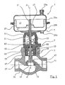
- FIG. 1 In general, a control device according to the invention is provided with the reference numeral 1.
- the actuator 1 comprises three main components, namely the control valve 3, a bolted to the control valve 3 upper part 5 and a rigidly coupled to the control valve 3 actuator, which is optionally grown for the realization of the actuator or can be added later.
- the actuator 7 is realized as a pneumatic drive and equipped with two pneumatic working chambers 11, 13 which are separated from each other by a membrane 15 airtight.
- a coupling ring 17 is attached, which allows a rigid coupling of the diaphragm 15 to a drive rod 21 of the actuator 7.
- the membrane 15 is clamped between two drive housing halves 23a, 23b, which limit the working chambers 11, 13, and in which pneumatic connections 25a, 25b are provided.
- a lower drive housing half 23 b has an output opening for passing through the two-part drive rod 21, which comprises an actuator-side drive rod part 31 and a valve-side output rod part 33. Both rod parts 31, 33 are frictionally and / or positively coupled to each other by a rod coupler 35, wherein the rod coupler 35 may be formed by two clamps screwed together. The clamps engage in a rod coupler near recess of the output rod portion 33 a.
- the control valve 3 has a valve housing 54 which defines an inlet 37 and a drain 41, wherein the inlet 37 is separated from the drain 41 via a valve seat passage 43.
- the valve seat passage 43 receives a valve seat ring 45, which cooperates with a valve member 47 closing and opening, so that a flow through the control valve 3 either approved, partially approved or can be locked.
- the valve member 47 is fixed to one end of the output rod member 33.
- the valve housing 54 is rigidly coupled to the housing of the actuator 7, with the aid of the upper part 5, which may be formed as a yoke, lantern and / or drive rod or drive shaft guide.
- the upper part 5 is realized as a one-piece component, which forms both a laterally accessible yoke structure 51 and a rod or waveguide insert 53.
- the upper part 5 is an upper through-opening 55, which is provided with an internal thread, the valve housing 54 is screwed, for which the rod or wave guide insert 53 of the upper part 5 has a corresponding external thread.
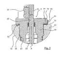
- the passage opening 55 is realized on the valve housing 54 by a neck 57, on the inner surface of which both the internal thread and the sealing surfaces are formed, wherein a leakage channel 61 extends radially through the vertical neck 57.
- the leakage channel 61 opens at an inner surface of the vertical neck 57 directly axially below the internal thread, wherein further below the sealing surfaces are formed, which cooperate with O-rings 63 of the rod or shaft guide insert 53.
- the rod or wave guide insert 53 has a sealed passage 65 for the implementation of the output rod portion 33.
- the passage 65 is extended in the form of a blind hole in the course towards the valve member 47, wherein in the blind hole-shaped extension an optionally axially biased seal package is arranged, which is connected by a plurality of sealing elements connected in series can be realized (see FIG. 2 ).
- the neck 57 has at its upper, the actuator 7 facing mounting side an annular, planar, radial screw abutment surface 71, which is perpendicular to the axial direction A, which corresponds to the translational adjustment direction of the control rod 21.
- the screw stop surface 71 has at a constant circumferential distance a plurality, preferably three receiving recesses 73, which may be formed, for example, as a blind hole. It is also possible for more than three such engagement recesses 73 to be formed on the screw stop surface 71.
- the screw abutment surface 71 cooperates with an opposite screw abutment counter surface 77 of a Montageradialabsatzes 75 of the upper part 5, which extends in the radial direction and the radial screw abutment counter surface 77 determines. Between the screw abutment counter surface 77 and the screw abutment surface 71 a forming a deformation buffer ring and disc-shaped base ring structure 81 is inserted. When screwing the upper part, the base ring structure 81 between the upper part 5 and the valve housing 54 is gradually deformed.
- the deformation buffer 81 has two basic functions, namely to achieve an anti-rotation lock and a predetermined setpoint position from upper part to valve part by means of a tolerated set deformation of the deformation buffer.
- the rotation ensures that the deformation buffer 81 is not rotated when screwing the upper part 5 in the valve housing 54 in the direction of rotation.
- the target deformation is realized by a plurality of target deformation zones formed by a part of the deformation buffer 81.
- the deformation zone is realized by a localized stamping, resulting in a convex curvature on one clamping side of the deformation buffer 81 and a concave impression on the other clamping side.
- the predetermined deformation zones are gradually deformed during the screwing of the upper part 5, that is to say when the deformation buffer 81 is braced. By means of this nominal deformation it is ensured that no excessive axial screwing forces possibly damaging the thread are applied and a sudden build-up of axial clamping forces is prevented.
- the inner diameter of the deformation buffer 81 substantially corresponds to the inner diameter of the passage 55.
- the outer diameter of the deformation buffer 81 substantially corresponds to the outer diameter of the radial shoulder 75.
- the ring width is substantially constant.
- the axial ring thickness is constant in the circumferential course.
- the deformation buffer 81 comprises on its annular surface (clamping side) 83 facing the valve housing 54 at least two, preferably three engagement lugs 85, all of which engage in the associated engagement recesses 73 in the screw abutment surface 71, thus when screwing and applying rotary Mit Meeting, the deformation buffer 81 whose circumferential position does not change.
- a corresponding engagement lug 85 can also be formed on the annular surface of the deformation buffer 81 facing the actuator 7, in which case the corresponding engagement depression on the screw stop counter surface 77 of the upper part 5 is to be formed.
- the deformation buffer 81 includes a plurality of indentations projecting convexly on an annular surface 83 and engaging with the screw abutment surface 71 or screw abutment counter surface 77.
- the protrusions 87 are plastically predetermined deformed to the Delay generation of clamping forces between the upper part 5 and the valve housing 54 with respect to the rotational path.
- the bulges 87 are concave on the annular surface side 89 of the base ring structure 81, while they are convex on the opposite annular surface 83.
- the engagement lugs 85 differ from the cambers 87 in that the axial strength of the engagement lug is greater than that of the camber 87, the camber 87 having a material thickness corresponding to the ring structure of the base ring structure 81, and the engagement lugs 85 the bulges 87 on the opposite side of the base ring structure 81 protrude.
- more than four such separate desired deformation zones in the form of bulges 87 at the same circumferential angular distances (about 60 °) are formed on the deformation buffer 81.
- the annular deformation buffer 81 has a final mounting tab 91 which is bent toward the top 5 or toward the valve housing 54, depending on the orientation of the engagement lobes and / or the buckling portions 87 of the desired deformation zone.
- the bending direction depends on which direction the engagement lugs 85 are directed. In FIG. 4 the engagement lugs 85 are directed toward the valve housing 54, so that the final mounting tab 91 is bent vertically upwards to the upper part 5.
Landscapes
- Engineering & Computer Science (AREA)
- General Engineering & Computer Science (AREA)
- Mechanical Engineering (AREA)
- Valve Housings (AREA)
Applications Claiming Priority (1)
| Application Number | Priority Date | Filing Date | Title |
|---|---|---|---|
| DE102013006777.4A DE102013006777A1 (de) | 2013-04-18 | 2013-04-18 | Stellgerät für eine verfahrenstechnische Anlage |
Publications (2)
| Publication Number | Publication Date |
|---|---|
| EP2792918A1 true EP2792918A1 (fr) | 2014-10-22 |
| EP2792918B1 EP2792918B1 (fr) | 2016-10-26 |
Family
ID=50542762
Family Applications (1)
| Application Number | Title | Priority Date | Filing Date |
|---|---|---|---|
| EP14001243.6A Active EP2792918B1 (fr) | 2013-04-18 | 2014-04-03 | Appareil de réglage pour une installation technologique |
Country Status (3)
| Country | Link |
|---|---|
| US (1) | US9528623B2 (fr) |
| EP (1) | EP2792918B1 (fr) |
| DE (1) | DE102013006777A1 (fr) |
Cited By (1)
| Publication number | Priority date | Publication date | Assignee | Title |
|---|---|---|---|---|
| EP4134575A1 (fr) * | 2021-08-11 | 2023-02-15 | Gemü Gebr. Müller Apparatebau GmbH & Co. Kommanditgesellschaft | Entraînement de soupape, agencement de soupape et procédé |
Families Citing this family (2)
| Publication number | Priority date | Publication date | Assignee | Title |
|---|---|---|---|---|
| DE202018105378U1 (de) * | 2018-09-19 | 2019-12-20 | Samson Aktiengesellschaft | Halter für einen Magnet, Stellarmaturpositionserfassungseinrichtung und Stellarmatur |
| WO2023069583A1 (fr) * | 2021-10-20 | 2023-04-27 | Clementina Clemco Holdings, Inc. | Valve doseuse pour milieux abrasifs |
Citations (10)
| Publication number | Priority date | Publication date | Assignee | Title |
|---|---|---|---|---|
| GB540325A (en) * | 1941-02-10 | 1941-10-14 | John Banks Dunlop | Nut-lock |
| US2456493A (en) * | 1947-02-26 | 1948-12-14 | Phillips B Drane | Time controlled valve |
| US3204925A (en) * | 1962-05-15 | 1965-09-07 | Montuori Enrico | Valve with nonrotating valve stem |
| US4452428A (en) * | 1981-12-24 | 1984-06-05 | Scaramucci John P | Bonnet locking system for a valve |
| GB2138912A (en) * | 1983-04-26 | 1984-10-31 | British Nuclear Fuels Ltd | Locking tab washer |
| US4943033A (en) * | 1988-09-20 | 1990-07-24 | Pacson Limited | Flow control valve |
| FR2712645A1 (fr) * | 1993-11-18 | 1995-05-24 | Vanatome | Rondelle pour le freinage d'un assemblage vis-écrou. |
| US6905108B2 (en) | 2001-11-15 | 2005-06-14 | Fisher Controls International Llc. | Control valve flow adjustment device |
| DE102005060120A1 (de) * | 2005-12-16 | 2007-06-21 | Danfoss A/S | Heizkörper-Einbauventil |
| DE102010025635B4 (de) | 2010-06-30 | 2012-05-31 | Samson Ag | Stellgerät |
Family Cites Families (20)
| Publication number | Priority date | Publication date | Assignee | Title |
|---|---|---|---|---|
| US2307440A (en) * | 1940-11-07 | 1943-01-05 | Wylie G Wilson | Sealing ring |
| US2316974A (en) * | 1941-12-02 | 1943-04-20 | Dresser Mfg Company | Saddle gasket |
| US2449119A (en) * | 1944-10-14 | 1948-09-14 | John R Holicer | Control fitting for liquefied petroleum gas tanks |
| US2657078A (en) * | 1949-08-19 | 1953-10-27 | John R Virgil | Gasket seal for pipe joints |
| US3175573A (en) * | 1962-06-04 | 1965-03-30 | Manning Maxwell & Moore Inc | Packing-adjusting means for capped valve |
| US3257095A (en) * | 1962-12-12 | 1966-06-21 | Chester A Siver | Valve construction particularly packed or sealed |
| US3463196A (en) * | 1967-09-08 | 1969-08-26 | Ernest T Richardson | Flange protector |
| US3721452A (en) * | 1971-02-22 | 1973-03-20 | Psi Prod Inc | Gasket assembly for pipe flanges |
| US3993284A (en) * | 1975-06-26 | 1976-11-23 | Acf Industries, Incorporated | Connection of actuator cylinder housing to valve bonnet |
| US4101138A (en) * | 1976-11-25 | 1978-07-18 | Fiat Societa Per Azioni | Gasket for internal combustion engines, incorporating locating pins |
| US4436310A (en) * | 1981-09-18 | 1984-03-13 | Toyota Jidosha Kogyo Kabushiki Kaisha | Sealing device for joint |
| US4421293A (en) * | 1981-09-28 | 1983-12-20 | Whitey Co. | End cap assembly |
| US4522536A (en) * | 1983-08-08 | 1985-06-11 | Vidrine Sharon J | Apparatus for and method of fluid sealing channeled flange connectors of under-water pipe line sections |
| DE3610541A1 (de) * | 1986-03-27 | 1987-10-01 | Lechler Elring Dichtungswerke | Zylinderkopfdichtung |
| US5145219A (en) * | 1990-08-01 | 1992-09-08 | Cajon Company | Tube coupling with gasket retainer |
| JPH0826101A (ja) * | 1994-07-13 | 1996-01-30 | Sumitomo Electric Ind Ltd | ブレーキ液圧制御装置 |
| FR2775328B1 (fr) * | 1998-02-26 | 2000-04-28 | Christian Loth | Joint d'etancheite pour bride de tuyauterie |
| US7364166B2 (en) * | 2003-01-24 | 2008-04-29 | Applied Engineered Surfaces, Inc. | Seal and retainer for a fluid connection |
| US20050280214A1 (en) * | 2004-06-22 | 2005-12-22 | Richards Jeffrey L | Elastomer coated screen gasket |
| ITMI20060037U1 (it) * | 2006-02-01 | 2007-08-02 | Caleffi Spa | Valvola perfezionata di sicurezza per caldaie murali |
-
2013
- 2013-04-18 DE DE102013006777.4A patent/DE102013006777A1/de not_active Withdrawn
-
2014
- 2014-04-03 EP EP14001243.6A patent/EP2792918B1/fr active Active
- 2014-04-18 US US14/256,057 patent/US9528623B2/en active Active
Patent Citations (10)
| Publication number | Priority date | Publication date | Assignee | Title |
|---|---|---|---|---|
| GB540325A (en) * | 1941-02-10 | 1941-10-14 | John Banks Dunlop | Nut-lock |
| US2456493A (en) * | 1947-02-26 | 1948-12-14 | Phillips B Drane | Time controlled valve |
| US3204925A (en) * | 1962-05-15 | 1965-09-07 | Montuori Enrico | Valve with nonrotating valve stem |
| US4452428A (en) * | 1981-12-24 | 1984-06-05 | Scaramucci John P | Bonnet locking system for a valve |
| GB2138912A (en) * | 1983-04-26 | 1984-10-31 | British Nuclear Fuels Ltd | Locking tab washer |
| US4943033A (en) * | 1988-09-20 | 1990-07-24 | Pacson Limited | Flow control valve |
| FR2712645A1 (fr) * | 1993-11-18 | 1995-05-24 | Vanatome | Rondelle pour le freinage d'un assemblage vis-écrou. |
| US6905108B2 (en) | 2001-11-15 | 2005-06-14 | Fisher Controls International Llc. | Control valve flow adjustment device |
| DE102005060120A1 (de) * | 2005-12-16 | 2007-06-21 | Danfoss A/S | Heizkörper-Einbauventil |
| DE102010025635B4 (de) | 2010-06-30 | 2012-05-31 | Samson Ag | Stellgerät |
Cited By (1)
| Publication number | Priority date | Publication date | Assignee | Title |
|---|---|---|---|---|
| EP4134575A1 (fr) * | 2021-08-11 | 2023-02-15 | Gemü Gebr. Müller Apparatebau GmbH & Co. Kommanditgesellschaft | Entraînement de soupape, agencement de soupape et procédé |
Also Published As
| Publication number | Publication date |
|---|---|
| US20140312259A1 (en) | 2014-10-23 |
| US9528623B2 (en) | 2016-12-27 |
| DE102013006777A1 (de) | 2014-10-23 |
| EP2792918B1 (fr) | 2016-10-26 |
Similar Documents
| Publication | Publication Date | Title |
|---|---|---|
| DE2701744C2 (fr) | ||
| EP1260751A2 (fr) | Collier de serrage, notamment raccord de tuyaux | |
| EP2792918B1 (fr) | Appareil de réglage pour une installation technologique | |
| WO2017084992A1 (fr) | Élément de raccord pour un raccord destiné à relier des conduites de fluide sous pression | |
| EP2740874B1 (fr) | Procédé et dispositif de fermeture d'une ouverture dans un corps, notamment dans un actionneur de porte | |
| EP3877686B1 (fr) | Ensemble de liaison de blocs pour une installation frigorifique d'un véhicule automobile, installation frigorifique et véhicule automobile | |
| EP3332159A1 (fr) | Dispositif de régulation d'écoulement de fluide | |
| DE102016105840A1 (de) | Membranventil | |
| EP3153755B1 (fr) | Bride compressible à assemblage contrôlé | |
| EP0575340B1 (fr) | Soupape, de preference soupape a vide | |
| WO2014044667A1 (fr) | Dispositif d'arrêt de sécurité et son procédé de fabrication | |
| EP2738526B1 (fr) | Appareil de mesure de débit | |
| WO2011057702A1 (fr) | Soupape présentant une protection contre le démontage et une aide au montage | |
| DE2058688C3 (de) | Mehrstufiger Membranantrieb zur Steuerung eines Stellglieds, insbesondere eines Ventils | |
| DE202005010066U1 (de) | Vorgespanntes Federpaket | |
| WO2007028696A1 (fr) | Vissage de tubulure, tubulure et joint axial pour un vissage de tubulure de ce type, et utilisation d'un vissage de tubulure | |
| EP3626950B1 (fr) | Soupape ainsi que procédé de fabrication d'une soupape | |
| EP4018467B1 (fr) | Manostat à membrane | |
| EP4098919B1 (fr) | Plaque de soupape permettant de rendre étanche une ouverture de soupape d'une soupape à vide | |
| DE102012004467A1 (de) | Klemmvorrichtung und elastisches Klemmelement | |
| DE102022130770A1 (de) | Doppelter Membranantrieb mit Sicherheitsfunktion | |
| DE102015214830A1 (de) | Kopplungseinheit | |
| EP2917626B1 (fr) | Raccord à brides | |
| DE10141176A1 (de) | Lösbare Verbindung zum Kuppeln eines Gaswechselventils einer Brennkraftmaschine mit einem Aktor | |
| DE102014015892A1 (de) | Stellarmatur umfassend eine Dichtanordnung |
Legal Events
| Date | Code | Title | Description |
|---|---|---|---|
| PUAI | Public reference made under article 153(3) epc to a published international application that has entered the european phase |
Free format text: ORIGINAL CODE: 0009012 |
|
| 17P | Request for examination filed |
Effective date: 20140403 |
|
| AK | Designated contracting states |
Kind code of ref document: A1 Designated state(s): AL AT BE BG CH CY CZ DE DK EE ES FI FR GB GR HR HU IE IS IT LI LT LU LV MC MK MT NL NO PL PT RO RS SE SI SK SM TR |
|
| AX | Request for extension of the european patent |
Extension state: BA ME |
|
| R17P | Request for examination filed (corrected) |
Effective date: 20150303 |
|
| RBV | Designated contracting states (corrected) |
Designated state(s): AL AT BE BG CH CY CZ DE DK EE ES FI FR GB GR HR HU IE IS IT LI LT LU LV MC MK MT NL NO PL PT RO RS SE SI SK SM TR |
|
| RIC1 | Information provided on ipc code assigned before grant |
Ipc: F16K 27/02 20060101ALI20160428BHEP Ipc: F16B 39/10 20060101ALI20160428BHEP Ipc: F16K 31/126 20060101AFI20160428BHEP |
|
| GRAP | Despatch of communication of intention to grant a patent |
Free format text: ORIGINAL CODE: EPIDOSNIGR1 |
|
| INTG | Intention to grant announced |
Effective date: 20160711 |
|
| GRAS | Grant fee paid |
Free format text: ORIGINAL CODE: EPIDOSNIGR3 |
|
| GRAA | (expected) grant |
Free format text: ORIGINAL CODE: 0009210 |
|
| AK | Designated contracting states |
Kind code of ref document: B1 Designated state(s): AL AT BE BG CH CY CZ DE DK EE ES FI FR GB GR HR HU IE IS IT LI LT LU LV MC MK MT NL NO PL PT RO RS SE SI SK SM TR |
|
| REG | Reference to a national code |
Ref country code: GB Ref legal event code: FG4D Free format text: NOT ENGLISH |
|
| REG | Reference to a national code |
Ref country code: CH Ref legal event code: EP |
|
| REG | Reference to a national code |
Ref country code: AT Ref legal event code: REF Ref document number: 840270 Country of ref document: AT Kind code of ref document: T Effective date: 20161115 |
|
| REG | Reference to a national code |
Ref country code: IE Ref legal event code: FG4D Free format text: LANGUAGE OF EP DOCUMENT: GERMAN |
|
| REG | Reference to a national code |
Ref country code: DE Ref legal event code: R096 Ref document number: 502014001767 Country of ref document: DE |
|
| REG | Reference to a national code |
Ref country code: LT Ref legal event code: MG4D |
|
| PG25 | Lapsed in a contracting state [announced via postgrant information from national office to epo] |
Ref country code: LV Free format text: LAPSE BECAUSE OF FAILURE TO SUBMIT A TRANSLATION OF THE DESCRIPTION OR TO PAY THE FEE WITHIN THE PRESCRIBED TIME-LIMIT Effective date: 20161026 |
|
| REG | Reference to a national code |
Ref country code: NL Ref legal event code: MP Effective date: 20161026 |
|
| REG | Reference to a national code |
Ref country code: FR Ref legal event code: PLFP Year of fee payment: 4 |
|
| PG25 | Lapsed in a contracting state [announced via postgrant information from national office to epo] |
Ref country code: NO Free format text: LAPSE BECAUSE OF FAILURE TO SUBMIT A TRANSLATION OF THE DESCRIPTION OR TO PAY THE FEE WITHIN THE PRESCRIBED TIME-LIMIT Effective date: 20170126 Ref country code: SE Free format text: LAPSE BECAUSE OF FAILURE TO SUBMIT A TRANSLATION OF THE DESCRIPTION OR TO PAY THE FEE WITHIN THE PRESCRIBED TIME-LIMIT Effective date: 20161026 Ref country code: GR Free format text: LAPSE BECAUSE OF FAILURE TO SUBMIT A TRANSLATION OF THE DESCRIPTION OR TO PAY THE FEE WITHIN THE PRESCRIBED TIME-LIMIT Effective date: 20170127 Ref country code: LT Free format text: LAPSE BECAUSE OF FAILURE TO SUBMIT A TRANSLATION OF THE DESCRIPTION OR TO PAY THE FEE WITHIN THE PRESCRIBED TIME-LIMIT Effective date: 20161026 |
|
| PG25 | Lapsed in a contracting state [announced via postgrant information from national office to epo] |
Ref country code: PL Free format text: LAPSE BECAUSE OF FAILURE TO SUBMIT A TRANSLATION OF THE DESCRIPTION OR TO PAY THE FEE WITHIN THE PRESCRIBED TIME-LIMIT Effective date: 20161026 Ref country code: NL Free format text: LAPSE BECAUSE OF FAILURE TO SUBMIT A TRANSLATION OF THE DESCRIPTION OR TO PAY THE FEE WITHIN THE PRESCRIBED TIME-LIMIT Effective date: 20161026 Ref country code: ES Free format text: LAPSE BECAUSE OF FAILURE TO SUBMIT A TRANSLATION OF THE DESCRIPTION OR TO PAY THE FEE WITHIN THE PRESCRIBED TIME-LIMIT Effective date: 20161026 Ref country code: FI Free format text: LAPSE BECAUSE OF FAILURE TO SUBMIT A TRANSLATION OF THE DESCRIPTION OR TO PAY THE FEE WITHIN THE PRESCRIBED TIME-LIMIT Effective date: 20161026 Ref country code: IS Free format text: LAPSE BECAUSE OF FAILURE TO SUBMIT A TRANSLATION OF THE DESCRIPTION OR TO PAY THE FEE WITHIN THE PRESCRIBED TIME-LIMIT Effective date: 20170226 Ref country code: HR Free format text: LAPSE BECAUSE OF FAILURE TO SUBMIT A TRANSLATION OF THE DESCRIPTION OR TO PAY THE FEE WITHIN THE PRESCRIBED TIME-LIMIT Effective date: 20161026 Ref country code: RS Free format text: LAPSE BECAUSE OF FAILURE TO SUBMIT A TRANSLATION OF THE DESCRIPTION OR TO PAY THE FEE WITHIN THE PRESCRIBED TIME-LIMIT Effective date: 20161026 Ref country code: PT Free format text: LAPSE BECAUSE OF FAILURE TO SUBMIT A TRANSLATION OF THE DESCRIPTION OR TO PAY THE FEE WITHIN THE PRESCRIBED TIME-LIMIT Effective date: 20170227 |
|
| REG | Reference to a national code |
Ref country code: DE Ref legal event code: R097 Ref document number: 502014001767 Country of ref document: DE |
|
| PG25 | Lapsed in a contracting state [announced via postgrant information from national office to epo] |
Ref country code: SK Free format text: LAPSE BECAUSE OF FAILURE TO SUBMIT A TRANSLATION OF THE DESCRIPTION OR TO PAY THE FEE WITHIN THE PRESCRIBED TIME-LIMIT Effective date: 20161026 Ref country code: DK Free format text: LAPSE BECAUSE OF FAILURE TO SUBMIT A TRANSLATION OF THE DESCRIPTION OR TO PAY THE FEE WITHIN THE PRESCRIBED TIME-LIMIT Effective date: 20161026 Ref country code: EE Free format text: LAPSE BECAUSE OF FAILURE TO SUBMIT A TRANSLATION OF THE DESCRIPTION OR TO PAY THE FEE WITHIN THE PRESCRIBED TIME-LIMIT Effective date: 20161026 Ref country code: RO Free format text: LAPSE BECAUSE OF FAILURE TO SUBMIT A TRANSLATION OF THE DESCRIPTION OR TO PAY THE FEE WITHIN THE PRESCRIBED TIME-LIMIT Effective date: 20161026 Ref country code: CZ Free format text: LAPSE BECAUSE OF FAILURE TO SUBMIT A TRANSLATION OF THE DESCRIPTION OR TO PAY THE FEE WITHIN THE PRESCRIBED TIME-LIMIT Effective date: 20161026 |
|
| PG25 | Lapsed in a contracting state [announced via postgrant information from national office to epo] |
Ref country code: SM Free format text: LAPSE BECAUSE OF FAILURE TO SUBMIT A TRANSLATION OF THE DESCRIPTION OR TO PAY THE FEE WITHIN THE PRESCRIBED TIME-LIMIT Effective date: 20161026 Ref country code: IT Free format text: LAPSE BECAUSE OF FAILURE TO SUBMIT A TRANSLATION OF THE DESCRIPTION OR TO PAY THE FEE WITHIN THE PRESCRIBED TIME-LIMIT Effective date: 20161026 Ref country code: BG Free format text: LAPSE BECAUSE OF FAILURE TO SUBMIT A TRANSLATION OF THE DESCRIPTION OR TO PAY THE FEE WITHIN THE PRESCRIBED TIME-LIMIT Effective date: 20170126 |
|
| PLBE | No opposition filed within time limit |
Free format text: ORIGINAL CODE: 0009261 |
|
| STAA | Information on the status of an ep patent application or granted ep patent |
Free format text: STATUS: NO OPPOSITION FILED WITHIN TIME LIMIT |
|
| 26N | No opposition filed |
Effective date: 20170727 |
|
| PG25 | Lapsed in a contracting state [announced via postgrant information from national office to epo] |
Ref country code: SI Free format text: LAPSE BECAUSE OF FAILURE TO SUBMIT A TRANSLATION OF THE DESCRIPTION OR TO PAY THE FEE WITHIN THE PRESCRIBED TIME-LIMIT Effective date: 20161026 |
|
| REG | Reference to a national code |
Ref country code: CH Ref legal event code: PL |
|
| REG | Reference to a national code |
Ref country code: IE Ref legal event code: MM4A |
|
| PG25 | Lapsed in a contracting state [announced via postgrant information from national office to epo] |
Ref country code: MC Free format text: LAPSE BECAUSE OF FAILURE TO SUBMIT A TRANSLATION OF THE DESCRIPTION OR TO PAY THE FEE WITHIN THE PRESCRIBED TIME-LIMIT Effective date: 20161026 |
|
| PG25 | Lapsed in a contracting state [announced via postgrant information from national office to epo] |
Ref country code: CH Free format text: LAPSE BECAUSE OF NON-PAYMENT OF DUE FEES Effective date: 20170430 Ref country code: LU Free format text: LAPSE BECAUSE OF NON-PAYMENT OF DUE FEES Effective date: 20170403 Ref country code: LI Free format text: LAPSE BECAUSE OF NON-PAYMENT OF DUE FEES Effective date: 20170430 |
|
| REG | Reference to a national code |
Ref country code: BE Ref legal event code: MM Effective date: 20170430 |
|
| PG25 | Lapsed in a contracting state [announced via postgrant information from national office to epo] |
Ref country code: IE Free format text: LAPSE BECAUSE OF NON-PAYMENT OF DUE FEES Effective date: 20170403 |
|
| REG | Reference to a national code |
Ref country code: FR Ref legal event code: PLFP Year of fee payment: 5 |
|
| PG25 | Lapsed in a contracting state [announced via postgrant information from national office to epo] |
Ref country code: BE Free format text: LAPSE BECAUSE OF NON-PAYMENT OF DUE FEES Effective date: 20170430 |
|
| PG25 | Lapsed in a contracting state [announced via postgrant information from national office to epo] |
Ref country code: MT Free format text: LAPSE BECAUSE OF FAILURE TO SUBMIT A TRANSLATION OF THE DESCRIPTION OR TO PAY THE FEE WITHIN THE PRESCRIBED TIME-LIMIT Effective date: 20161026 |
|
| PG25 | Lapsed in a contracting state [announced via postgrant information from national office to epo] |
Ref country code: HU Free format text: LAPSE BECAUSE OF FAILURE TO SUBMIT A TRANSLATION OF THE DESCRIPTION OR TO PAY THE FEE WITHIN THE PRESCRIBED TIME-LIMIT; INVALID AB INITIO Effective date: 20140403 |
|
| PG25 | Lapsed in a contracting state [announced via postgrant information from national office to epo] |
Ref country code: CY Free format text: LAPSE BECAUSE OF FAILURE TO SUBMIT A TRANSLATION OF THE DESCRIPTION OR TO PAY THE FEE WITHIN THE PRESCRIBED TIME-LIMIT Effective date: 20161026 |
|
| PG25 | Lapsed in a contracting state [announced via postgrant information from national office to epo] |
Ref country code: MK Free format text: LAPSE BECAUSE OF FAILURE TO SUBMIT A TRANSLATION OF THE DESCRIPTION OR TO PAY THE FEE WITHIN THE PRESCRIBED TIME-LIMIT Effective date: 20161026 |
|
| PG25 | Lapsed in a contracting state [announced via postgrant information from national office to epo] |
Ref country code: TR Free format text: LAPSE BECAUSE OF FAILURE TO SUBMIT A TRANSLATION OF THE DESCRIPTION OR TO PAY THE FEE WITHIN THE PRESCRIBED TIME-LIMIT Effective date: 20161026 |
|
| PG25 | Lapsed in a contracting state [announced via postgrant information from national office to epo] |
Ref country code: AL Free format text: LAPSE BECAUSE OF FAILURE TO SUBMIT A TRANSLATION OF THE DESCRIPTION OR TO PAY THE FEE WITHIN THE PRESCRIBED TIME-LIMIT Effective date: 20161026 |
|
| REG | Reference to a national code |
Ref country code: AT Ref legal event code: MM01 Ref document number: 840270 Country of ref document: AT Kind code of ref document: T Effective date: 20190403 |
|
| PG25 | Lapsed in a contracting state [announced via postgrant information from national office to epo] |
Ref country code: AT Free format text: LAPSE BECAUSE OF NON-PAYMENT OF DUE FEES Effective date: 20190403 |
|
| PGFP | Annual fee paid to national office [announced via postgrant information from national office to epo] |
Ref country code: FR Payment date: 20210423 Year of fee payment: 8 |
|
| PGFP | Annual fee paid to national office [announced via postgrant information from national office to epo] |
Ref country code: GB Payment date: 20210422 Year of fee payment: 8 |
|
| GBPC | Gb: european patent ceased through non-payment of renewal fee |
Effective date: 20220403 |
|
| PG25 | Lapsed in a contracting state [announced via postgrant information from national office to epo] |
Ref country code: GB Free format text: LAPSE BECAUSE OF NON-PAYMENT OF DUE FEES Effective date: 20220403 Ref country code: FR Free format text: LAPSE BECAUSE OF NON-PAYMENT OF DUE FEES Effective date: 20220430 |
|
| REG | Reference to a national code |
Ref country code: DE Ref legal event code: R082 Ref document number: 502014001767 Country of ref document: DE Representative=s name: SKM-IP SCHMID KRAUSS KUTTENKEULER MALESCHA SCH, DE |
|
| P01 | Opt-out of the competence of the unified patent court (upc) registered |
Effective date: 20230713 |
|
| PGFP | Annual fee paid to national office [announced via postgrant information from national office to epo] |
Ref country code: DE Payment date: 20240418 Year of fee payment: 11 |