EP2792549A1 - Center console - Google Patents
Center console Download PDFInfo
- Publication number
- EP2792549A1 EP2792549A1 EP12858620.3A EP12858620A EP2792549A1 EP 2792549 A1 EP2792549 A1 EP 2792549A1 EP 12858620 A EP12858620 A EP 12858620A EP 2792549 A1 EP2792549 A1 EP 2792549A1
- Authority
- EP
- European Patent Office
- Prior art keywords
- box
- shock absorption
- wall
- console
- upper wall
- Prior art date
- Legal status (The legal status is an assumption and is not a legal conclusion. Google has not performed a legal analysis and makes no representation as to the accuracy of the status listed.)
- Withdrawn
Links
- 230000035939 shock Effects 0.000 claims abstract description 58
- 238000010521 absorption reaction Methods 0.000 claims abstract description 46
- 239000011347 resin Substances 0.000 description 4
- 229920005989 resin Polymers 0.000 description 4
- 239000000470 constituent Substances 0.000 description 3
- 238000000034 method Methods 0.000 description 2
- 238000012986 modification Methods 0.000 description 2
- 230000004048 modification Effects 0.000 description 2
- 230000006866 deterioration Effects 0.000 description 1
- 235000021189 garnishes Nutrition 0.000 description 1
Images



Classifications
-
- B—PERFORMING OPERATIONS; TRANSPORTING
- B60—VEHICLES IN GENERAL
- B60R—VEHICLES, VEHICLE FITTINGS, OR VEHICLE PARTS, NOT OTHERWISE PROVIDED FOR
- B60R21/00—Arrangements or fittings on vehicles for protecting or preventing injuries to occupants or pedestrians in case of accidents or other traffic risks
- B60R21/02—Occupant safety arrangements or fittings, e.g. crash pads
- B60R21/055—Padded or energy-absorbing fittings, e.g. seat belt anchors
-
- B—PERFORMING OPERATIONS; TRANSPORTING
- B60—VEHICLES IN GENERAL
- B60R—VEHICLES, VEHICLE FITTINGS, OR VEHICLE PARTS, NOT OTHERWISE PROVIDED FOR
- B60R7/00—Stowing or holding appliances inside vehicle primarily intended for personal property smaller than suit-cases, e.g. travelling articles, or maps
- B60R7/04—Stowing or holding appliances inside vehicle primarily intended for personal property smaller than suit-cases, e.g. travelling articles, or maps in driver or passenger space, e.g. using racks
-
- B—PERFORMING OPERATIONS; TRANSPORTING
- B60—VEHICLES IN GENERAL
- B60N—SEATS SPECIALLY ADAPTED FOR VEHICLES; VEHICLE PASSENGER ACCOMMODATION NOT OTHERWISE PROVIDED FOR
- B60N3/00—Arrangements or adaptations of other passenger fittings, not otherwise provided for
- B60N3/10—Arrangements or adaptations of other passenger fittings, not otherwise provided for of receptacles for food or beverages, e.g. refrigerated
- B60N3/105—Arrangements or adaptations of other passenger fittings, not otherwise provided for of receptacles for food or beverages, e.g. refrigerated for receptables of different size or shape
-
- B—PERFORMING OPERATIONS; TRANSPORTING
- B60—VEHICLES IN GENERAL
- B60R—VEHICLES, VEHICLE FITTINGS, OR VEHICLE PARTS, NOT OTHERWISE PROVIDED FOR
- B60R13/00—Elements for body-finishing, identifying, or decorating; Arrangements or adaptations for advertising purposes
- B60R13/02—Internal Trim mouldings ; Internal Ledges; Wall liners for passenger compartments; Roof liners
- B60R13/0262—Mid-console liners
-
- B—PERFORMING OPERATIONS; TRANSPORTING
- B60—VEHICLES IN GENERAL
- B60R—VEHICLES, VEHICLE FITTINGS, OR VEHICLE PARTS, NOT OTHERWISE PROVIDED FOR
- B60R11/00—Arrangements for holding or mounting articles, not otherwise provided for
- B60R2011/0001—Arrangements for holding or mounting articles, not otherwise provided for characterised by position
- B60R2011/0003—Arrangements for holding or mounting articles, not otherwise provided for characterised by position inside the vehicle
- B60R2011/0007—Mid-console
-
- B—PERFORMING OPERATIONS; TRANSPORTING
- B60—VEHICLES IN GENERAL
- B60R—VEHICLES, VEHICLE FITTINGS, OR VEHICLE PARTS, NOT OTHERWISE PROVIDED FOR
- B60R11/00—Arrangements for holding or mounting articles, not otherwise provided for
- B60R2011/0001—Arrangements for holding or mounting articles, not otherwise provided for characterised by position
- B60R2011/0003—Arrangements for holding or mounting articles, not otherwise provided for characterised by position inside the vehicle
- B60R2011/0012—Seats or parts thereof
- B60R2011/0014—Arm-rests
Definitions
- the present invention relates to a center console situated between the right and left front seats of an automobile. More specifically, the present invention relates to a center console provided with a structure capable of absorbing shock acting on a rear portion of the console cover from above.
- Japanese Laid-Open Patent Publication No. 2010-143502 discloses a technique in which a shock absorption bracket is provided at a rear portion of a box of a center console.
- the bracket has a shock absorption portion bent into an M-shape as seen from a side view.
- a console cover is mounted to an upper surface of the shock absorption bracket by a hinge.
- the shock absorption bracket is a member separate from the proper constituent member of the center console. This may lead to deterioration in the design property of the center console.
- a center console has a box, a console door and a shock absorption portion.
- the box is installed on a floor in a vehicle interior.
- the console door is connected to an upper wall of a rear portion of the box via a hinge shaft, and rotates using the hinge shaft as a fulcrum so that an opening of the box upper is opened and closed.
- the shock absorption portion divides the rear portion of the box into the upper wall and a lower wall.
- the shock absorption portion connects the upper wall and the lower wall to each other with a step therebetween.
- the shock absorption portion is set to be thinner than the upper wall and the lower wall.
- a center console is provided between the right and left front seats of an automobile.
- the center console has a box 10 and a console door 30.
- the box 10 is installed on a floor F.
- the box 10 has a storage space in its interior, and an opening in the upper of the storage space. The opening allows access to the storage space.
- the console door 30 has a configuration covering the opening of the box 10, and is connected to the box 10 via a hinge shaft 38 ( FIG. 3 ).
- a cup holder 40 is provided in a front portion (the left-hand side in the drawing) of the console door 30 on an upper surface of the box 10 ( FIG 1 ).
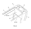
- the box 10 has a box outer 12 and a box inner 16 ( FIG. 2 ).
- the box outer 12 is formed of resin, and constitutes an outer shell of the box 10.
- the box inner 16 is formed of resin, and is situated within the box outer 12.
- the box inner 16 has a rear wall 16a erecting at the rear portion, side walls 16b continuous with both ends of the rear wall 16a, and corner portions 16c connecting the rear wall 16a and the side walls 16b to each other such that they are substantially orthogonal to each other.
- a shock absorption wall 20 is formed at the rear wall 16a and the rear portions of the side walls 16b, and is provided with a shock absorption portion 22.
- the shock absorption portion 22 has a rear portion 22a formed on the rear wall 16a, and side portions 22b and vertical portions 22c formed on the side walls 16b.
- the rear portion 22a extends horizontally along the rear wall 16a, dividing the rear wall 16a into upper and lower regions.
- the side portions 22b extend horizontally from the rear portion 22a, dividing the rear regions of the side portions 22b into upper and lower regions.
- the vertical portions 22c extend from the front ends of the side portions 22b down to the bottom of the storage space.
- the shock absorption wall 20 is divided into an upper wall portion (upper wall) 20U and a lower wall portion (lower wall) 20L.
- the upper wall portion 20U and the lower wall portion 20L are connected together, with a step created by the shock absorption portion 22 lying therebetween.
- the shock absorption portion 22 is set to be thinner than the upper wall portion 20U and the lower wall portion 20L of the shock absorption wall 20 ( FIG. 3 ). Due to the shock absorption portion 22, the lower wall portion 20L protrudes farther into the storage space of the box 10 than the upper wall portion 20U.
- a hinge bracket 24 is integrally formed with the upper portion of the rear wall 16a of the box inner 16. That is, the hinge bracket 24 is integrally formed with the upper wall portion 20U of the shock absorption portion 20.
- the console door 30 has a door outer 32 formed of resin, and a door inner 34 formed of resin ( FIG. 3 ).
- the door inner 34 is situated on the inner side of the door outer 32.
- a hinge bracket 36 is integrally formed with the rear lower surface (on the right-hand side in the drawing) of the door inner 34.
- the hinge bracket 36 and the hinge bracket 24 of the box inner 16 are connected by the hinge shaft 38.
- the hinge constituent member is accommodated on the inner side of a rear garnish 14 attached to the rear of the box outer 12 ( FIG. 3 ).
- the console door 30 has a rear portion connected to the box 10 by the hinge shaft 38.
- the console door 30 rotates using the hinge shaft 38 as the fulcrum. This makes it possible to open and close the opening of the box 10.
- a shock of not less than a predetermined value may be applied to the rear portion of the console door 30 due to the occupant seated in the rear seat.
- the shock is transmitted to the shock absorption wall 20 of the box 10 (the box inner 16) via the hinge shaft 38.
- the thin-walled shock absorption portion 22 of the shock absorption wall 20 is fractured.
- the upper wall portion 20U of the shock absorption wall 20 moves from the position shown in FIG. 4 to the position shown in FIG. 5 .
- the shock absorption portion 22 is continuous from the rear wall 16a of the box inner 16 to parts of both side walls 16b via the corner portions 16c on both sides.
- the fracture of the shock absorption portion 22 due to the shock occurs continuously from the rear wall 16a to part of both side walls 16b.
- this is apparent from the configuration of a continuous crack 22d generated in the shock absorption portion 22 after the shock absorption.
- the fracture of the shock absorption portion 22 occurs continuously from the rear wall 16a of the box inner 16 to parts of both side walls 16b.
- the upper wall portion 20U of the shock absorption wall 20 properly moves downwardly. This makes it possible to absorb the shock.
- the shock absorption wall 20 is formed on the rear wall 16a and both side walls 16b of the box inner 16.
- the upper wall portion 20U and the lower wall portion 20L are connected in a step-like configuration due to the shock absorption portion 22.
- the lower wall portion 20L may protrude further into the storage space of the box 10 than the upper wall portion 20U due to the shock absorption portion 22.
- the lower wall portion 20L may protrude further to the exterior of the box 10 than the upper wall portion 20U due to the shock absorption portion 22.
- the console door 30 may have a rear portion connected to the rear portion of the box 10 via the hinge shaft 38.
- the console door may have a side portion connected to the left portion or the right portion of the box 10 via a hinge shaft.
Landscapes
- Engineering & Computer Science (AREA)
- Mechanical Engineering (AREA)
- Vehicle Step Arrangements And Article Storage (AREA)
Abstract
Description
- The present invention relates to a center console situated between the right and left front seats of an automobile. More specifically, the present invention relates to a center console provided with a structure capable of absorbing shock acting on a rear portion of the console cover from above.
- Japanese Laid-Open Patent Publication No.
2010-143502 - The shock absorption bracket is a member separate from the proper constituent member of the center console. This may lead to deterioration in the design property of the center console. In view of this, it might be possible to adopt a technique in which the rigidity of the box, which is a constituent member of the center console, is reduced. A reduction in the rigidity of the box, however, would result in wobbling of the box when an elbow or the like were placed on an upper surface of a console door when using it as an armrest. This would create a loss in the stability of the box.
- Thus, there is a need in the art for a structure capable of absorbing a shock acting from above on a rear portion of a console cover while securing the adequate design property of the center console and the rigidity thereof as needed in the normal state.
- According to an aspect of the present invention, a center console has a box, a console door and a shock absorption portion. The box is installed on a floor in a vehicle interior. The console door is connected to an upper wall of a rear portion of the box via a hinge shaft, and rotates using the hinge shaft as a fulcrum so that an opening of the box upper is opened and closed. The shock absorption portion divides the rear portion of the box into the upper wall and a lower wall. The shock absorption portion connects the upper wall and the lower wall to each other with a step therebetween. The shock absorption portion is set to be thinner than the upper wall and the lower wall.
- As a result, it is possible to secure the design property of the center console and the rigidity thereof as required in the normal state. When a shock acts on the rear portion of the console door from above, the shock is transmitted to the upper wall of the shock absorption wall via the hinge shaft, and the shock absorption wall is fractured. As a result, the upper wall is separated from the lower wall at the shock absorption portion and moves downwards. This absorbs the shock.
-
-
FIG. 1 is a perspective view of a portion of a center console; -
FIG. 2 is a perspective view of a rear portion of a box of the center console; -
FIG. 3 is an enlarged vertical cross-sectional view of a rear upper portion of the center console; -
FIG. 4 is a schematic view of a shock absorption wall; -
FIG. 5 is a schematic view of the shock absorption wall after absorbing a shock; and -
FIG. 6 is an enlarged perspective view of a portion of the shock absorption wall after absorbing a shock. - An embodiment of the present invention will be described with reference to the drawings. A center console is provided between the right and left front seats of an automobile. The center console has a
box 10 and aconsole door 30. As shown inFIG. 1 , thebox 10 is installed on a floor F. Thebox 10 has a storage space in its interior, and an opening in the upper of the storage space. The opening allows access to the storage space. Theconsole door 30 has a configuration covering the opening of thebox 10, and is connected to thebox 10 via a hinge shaft 38 (FIG. 3 ). - A
cup holder 40 is provided in a front portion (the left-hand side in the drawing) of theconsole door 30 on an upper surface of the box 10 (FIG 1 ). - The
box 10 has a box outer 12 and a box inner 16 (FIG. 2 ). The box outer 12 is formed of resin, and constitutes an outer shell of thebox 10. The box inner 16 is formed of resin, and is situated within the box outer 12. The box inner 16 has a rear wall 16a erecting at the rear portion, side walls 16b continuous with both ends of the rear wall 16a, and corner portions 16c connecting the rear wall 16a and the side walls 16b to each other such that they are substantially orthogonal to each other. - As shown in
FIG. 2 , ashock absorption wall 20 is formed at the rear wall 16a and the rear portions of the side walls 16b, and is provided with ashock absorption portion 22. Theshock absorption portion 22 has arear portion 22a formed on the rear wall 16a, and side portions 22b and vertical portions 22c formed on the side walls 16b. Therear portion 22a extends horizontally along the rear wall 16a, dividing the rear wall 16a into upper and lower regions. The side portions 22b extend horizontally from therear portion 22a, dividing the rear regions of the side portions 22b into upper and lower regions. The vertical portions 22c extend from the front ends of the side portions 22b down to the bottom of the storage space. - With the
shock absorption portion 22 serving as a boundary, theshock absorption wall 20 is divided into an upper wall portion (upper wall) 20U and a lower wall portion (lower wall) 20L. Theupper wall portion 20U and thelower wall portion 20L are connected together, with a step created by theshock absorption portion 22 lying therebetween. Theshock absorption portion 22 is set to be thinner than theupper wall portion 20U and thelower wall portion 20L of the shock absorption wall 20 (FIG. 3 ). Due to theshock absorption portion 22, thelower wall portion 20L protrudes farther into the storage space of thebox 10 than theupper wall portion 20U. - A
hinge bracket 24 is integrally formed with the upper portion of the rear wall 16a of the box inner 16. That is, thehinge bracket 24 is integrally formed with theupper wall portion 20U of theshock absorption portion 20. - The
console door 30 has a door outer 32 formed of resin, and a door inner 34 formed of resin (FIG. 3 ). The door inner 34 is situated on the inner side of the door outer 32. Ahinge bracket 36 is integrally formed with the rear lower surface (on the right-hand side in the drawing) of the door inner 34. Thehinge bracket 36 and thehinge bracket 24 of the box inner 16 are connected by thehinge shaft 38. The hinge constituent member is accommodated on the inner side of arear garnish 14 attached to the rear of the box outer 12 (FIG. 3 ). - The
console door 30 has a rear portion connected to thebox 10 by thehinge shaft 38. Theconsole door 30 rotates using thehinge shaft 38 as the fulcrum. This makes it possible to open and close the opening of thebox 10. - In the case of back collision or the like of the automobile, a shock of not less than a predetermined value may be applied to the rear portion of the
console door 30 due to the occupant seated in the rear seat. In this case, the shock is transmitted to theshock absorption wall 20 of the box 10 (the box inner 16) via thehinge shaft 38. As a result, the thin-walledshock absorption portion 22 of theshock absorption wall 20 is fractured. In absorbing the shock, theupper wall portion 20U of theshock absorption wall 20 moves from the position shown inFIG. 4 to the position shown inFIG. 5 . - The
shock absorption portion 22 is continuous from the rear wall 16a of the box inner 16 to parts of both side walls 16b via the corner portions 16c on both sides. Thus, the fracture of theshock absorption portion 22 due to the shock occurs continuously from the rear wall 16a to part of both side walls 16b. As shown inFIG. 6 , this is apparent from the configuration of a continuous crack 22d generated in theshock absorption portion 22 after the shock absorption. - The fracture of the
shock absorption portion 22 occurs continuously from the rear wall 16a of the box inner 16 to parts of both side walls 16b. Thus, theupper wall portion 20U of theshock absorption wall 20 properly moves downwardly. This makes it possible to absorb the shock. - The
shock absorption wall 20 is formed on the rear wall 16a and both side walls 16b of the box inner 16. Theupper wall portion 20U and thelower wall portion 20L are connected in a step-like configuration due to theshock absorption portion 22. Thus, it is possible to maintain the adequate design property of the center console. It is also possible to secure the rigidity as required when an elbow or the like is placed on the upper surface of theconsole door 30 when using it as an armrest in the normal state. - While the embodiments of invention have been described with reference to specific configurations, it will be apparent to those skilled in the art that many alternatives, modifications and variations may be made without departing from the scope of the present invention. Accordingly, embodiments of the present invention are intended to embrace all such alternatives, modifications and variations that may fall within the spirit and scope of the appended claims. For example, embodiments of the present invention should not be limited to the representative configurations, but may be modified, for example, as described below.
- As shown in
FIG. 2 , thelower wall portion 20L may protrude further into the storage space of thebox 10 than theupper wall portion 20U due to theshock absorption portion 22. Alternatively, thelower wall portion 20L may protrude further to the exterior of thebox 10 than theupper wall portion 20U due to theshock absorption portion 22. - As shown in
FIG. 3 , theconsole door 30 may have a rear portion connected to the rear portion of thebox 10 via thehinge shaft 38. Alternatively, the console door may have a side portion connected to the left portion or the right portion of thebox 10 via a hinge shaft.
Claims (2)
- A center console comprising:a box installed on a floor in a vehicle interior;a console door connected to an upper wall of a rear portion of the box via a hinge shaft, and rotates using the hinge shaft as a fulcrum so that an opening of the box upper is opened and closed; anda shock absorption portion configured to divide the rear portion of the box into the upper wall and a lower wall, the shock absorption portion configured to connect the upper wall and the lower wall to each other with a step therebetween, the shock absorption portion set to be thinner than the upper wall and the lower wall.
- The center console as in claim 1, wherein the shock absorption portion is formed on a rear wall and side walls of the box, wherein the side walls are continuous with both sides of the rear wall via corner portions.
Applications Claiming Priority (2)
| Application Number | Priority Date | Filing Date | Title |
|---|---|---|---|
| JP2011275578A JP2013124069A (en) | 2011-12-16 | 2011-12-16 | center console |
| PCT/JP2012/080057 WO2013088919A1 (en) | 2011-12-16 | 2012-11-20 | Center console |
Publications (2)
| Publication Number | Publication Date |
|---|---|
| EP2792549A1 true EP2792549A1 (en) | 2014-10-22 |
| EP2792549A4 EP2792549A4 (en) | 2015-08-12 |
Family
ID=48612374
Family Applications (1)
| Application Number | Title | Priority Date | Filing Date |
|---|---|---|---|
| EP12858620.3A Withdrawn EP2792549A4 (en) | 2011-12-16 | 2012-11-20 | CENTRAL CONSOLE |
Country Status (5)
| Country | Link |
|---|---|
| US (1) | US9199595B2 (en) |
| EP (1) | EP2792549A4 (en) |
| JP (1) | JP2013124069A (en) |
| CN (1) | CN103998293A (en) |
| WO (1) | WO2013088919A1 (en) |
Cited By (1)
| Publication number | Priority date | Publication date | Assignee | Title |
|---|---|---|---|---|
| US9925927B2 (en) | 2014-05-29 | 2018-03-27 | Calsonic Kansei Corporation | Console box |
Families Citing this family (7)
| Publication number | Priority date | Publication date | Assignee | Title |
|---|---|---|---|---|
| JP6548444B2 (en) * | 2015-04-24 | 2019-07-24 | カルソニックカンセイ株式会社 | Console Box |
| JP2016203858A (en) * | 2015-04-24 | 2016-12-08 | カルソニックカンセイ株式会社 | Console box |
| JP2016203859A (en) * | 2015-04-24 | 2016-12-08 | カルソニックカンセイ株式会社 | Console box |
| DE102017208381A1 (en) * | 2016-05-27 | 2017-11-30 | Ford Global Technologies, Llc | MOUNTING HOLDER FOR CONSOLE |
| US9873382B1 (en) * | 2016-07-01 | 2018-01-23 | Toyota Motor Engineering & Manufacturing North America, Inc. | Console assemblies having support structures with side impact reinforcements |
| JP7064967B2 (en) * | 2018-06-05 | 2022-05-11 | トヨタ自動車東日本株式会社 | Rear console for automobiles |
| USD1060173S1 (en) * | 2022-02-07 | 2025-02-04 | Jaguar Land Rover Limited | Interior panel for a vehicle |
Family Cites Families (15)
| Publication number | Priority date | Publication date | Assignee | Title |
|---|---|---|---|---|
| GB1535347A (en) | 1975-11-03 | 1978-12-13 | Daimler Benz Ag | Glove compartment in a vehicle |
| JP2585730Y2 (en) * | 1992-06-01 | 1998-11-25 | 日産自動車株式会社 | Automotive glove box |
| DE19625295A1 (en) * | 1995-06-30 | 1997-01-02 | Volkswagen Ag | Deforming element for support of section added to structure |
| JP2004090739A (en) * | 2002-08-30 | 2004-03-25 | Imasen Electric Ind Co Ltd | Vehicle ashtray |
| JP4172231B2 (en) * | 2002-09-09 | 2008-10-29 | トヨタ紡織株式会社 | Shock absorption structure |
| JP4411430B2 (en) * | 2003-11-27 | 2010-02-10 | 内浜化成株式会社 | Resin parts for vehicles |
| US7731258B2 (en) * | 2005-06-14 | 2010-06-08 | Ford Global Technologies, Llc | Center floor console sliding armrest |
| JP4285525B2 (en) * | 2006-10-23 | 2009-06-24 | 三菱自動車エンジニアリング株式会社 | Vehicle floor console structure |
| DE102006051948B3 (en) * | 2006-11-01 | 2008-06-05 | Faurecia Innenraum Systeme Gmbh | Storage compartment i.e. glove compartment, for use in e.g. dash panel of motor vehicle, has walls formed for collapsing, which is telescopically carried out, where walls are designed as housing walls and partition walls |
| JP2008174027A (en) * | 2007-01-16 | 2008-07-31 | Inoac Corp | Console box |
| JP2008230587A (en) * | 2007-02-22 | 2008-10-02 | Calsonic Kansei Corp | Console mounting part structure |
| JP2009166599A (en) * | 2008-01-15 | 2009-07-30 | Toyoda Gosei Co Ltd | Console box |
| JP4485582B2 (en) * | 2008-07-11 | 2010-06-23 | 本田技研工業株式会社 | Vehicle load transmission |
| JP5165491B2 (en) * | 2008-07-31 | 2013-03-21 | ダイキョーニシカワ株式会社 | Rear console |
| JP5280829B2 (en) | 2008-12-22 | 2013-09-04 | カルソニックカンセイ株式会社 | Console shock absorber structure |
-
2011
- 2011-12-16 JP JP2011275578A patent/JP2013124069A/en active Pending
-
2012
- 2012-11-20 WO PCT/JP2012/080057 patent/WO2013088919A1/en not_active Ceased
- 2012-11-20 EP EP12858620.3A patent/EP2792549A4/en not_active Withdrawn
- 2012-11-20 US US14/364,663 patent/US9199595B2/en not_active Expired - Fee Related
- 2012-11-20 CN CN201280061756.6A patent/CN103998293A/en active Pending
Cited By (1)
| Publication number | Priority date | Publication date | Assignee | Title |
|---|---|---|---|---|
| US9925927B2 (en) | 2014-05-29 | 2018-03-27 | Calsonic Kansei Corporation | Console box |
Also Published As
| Publication number | Publication date |
|---|---|
| EP2792549A4 (en) | 2015-08-12 |
| JP2013124069A (en) | 2013-06-24 |
| US9199595B2 (en) | 2015-12-01 |
| WO2013088919A1 (en) | 2013-06-20 |
| CN103998293A (en) | 2014-08-20 |
| US20140333085A1 (en) | 2014-11-13 |
Similar Documents
| Publication | Publication Date | Title |
|---|---|---|
| US9199595B2 (en) | Center consoles | |
| ES2266223T3 (en) | ULTRALIGINAL SLIDING DOOR FOR A VEHICLE. | |
| EP2548787B1 (en) | Vehicle front part structure | |
| JP4938541B2 (en) | Console box bottom mounting structure | |
| EP2789526A1 (en) | Vehicle body lower structure | |
| US9925927B2 (en) | Console box | |
| US7891707B2 (en) | Steering hanger beam | |
| US8708387B2 (en) | Console box | |
| US9783132B2 (en) | Side door trim for vehicle | |
| JP2014205375A (en) | Vehicular interior member | |
| JP2014091488A (en) | Knee collision protective structure of vehicle | |
| KR20140032775A (en) | Upper vehicle body structure of vehicle with a sun roof | |
| US9873398B2 (en) | Vehicle interior structure | |
| JP6599928B2 (en) | Console assembly having a support structure with lateral impact reinforcement | |
| JP2005029120A (en) | Front body structure | |
| JP5801370B2 (en) | Vehicle door | |
| JP4265284B2 (en) | Vehicle armrest structure | |
| KR102114067B1 (en) | Cup holder for vehicle | |
| US20110089673A1 (en) | Vehicle passenger compartment cladding element for a column of a motor vehicle | |
| JP6548444B2 (en) | Console Box | |
| JP5257597B2 (en) | Mounting structure for vehicle article storage section | |
| JP2013220789A (en) | Vehicle upper part structure | |
| JP4228737B2 (en) | Vehicle side door | |
| JP2008087510A (en) | Car side body structure | |
| JP6308800B2 (en) | Car container structure |
Legal Events
| Date | Code | Title | Description |
|---|---|---|---|
| PUAI | Public reference made under article 153(3) epc to a published international application that has entered the european phase |
Free format text: ORIGINAL CODE: 0009012 |
|
| 17P | Request for examination filed |
Effective date: 20140616 |
|
| AK | Designated contracting states |
Kind code of ref document: A1 Designated state(s): AL AT BE BG CH CY CZ DE DK EE ES FI FR GB GR HR HU IE IS IT LI LT LU LV MC MK MT NL NO PL PT RO RS SE SI SK SM TR |
|
| DAX | Request for extension of the european patent (deleted) | ||
| RA4 | Supplementary search report drawn up and despatched (corrected) |
Effective date: 20150714 |
|
| RIC1 | Information provided on ipc code assigned before grant |
Ipc: B60R 7/04 20060101AFI20150708BHEP |
|
| GRAP | Despatch of communication of intention to grant a patent |
Free format text: ORIGINAL CODE: EPIDOSNIGR1 |
|
| STAA | Information on the status of an ep patent application or granted ep patent |
Free format text: STATUS: GRANT OF PATENT IS INTENDED |
|
| INTG | Intention to grant announced |
Effective date: 20170614 |
|
| STAA | Information on the status of an ep patent application or granted ep patent |
Free format text: STATUS: THE APPLICATION IS DEEMED TO BE WITHDRAWN |
|
| 18D | Application deemed to be withdrawn |
Effective date: 20171025 |