EP2792238A1 - Line roller and fishing line guide mechanism using same - Google Patents
Line roller and fishing line guide mechanism using same Download PDFInfo
- Publication number
- EP2792238A1 EP2792238A1 EP14162880.0A EP14162880A EP2792238A1 EP 2792238 A1 EP2792238 A1 EP 2792238A1 EP 14162880 A EP14162880 A EP 14162880A EP 2792238 A1 EP2792238 A1 EP 2792238A1
- Authority
- EP
- European Patent Office
- Prior art keywords
- guide
- peripheral surface
- line roller
- outer peripheral
- race
- Prior art date
- Legal status (The legal status is an assumption and is not a legal conclusion. Google has not performed a legal analysis and makes no representation as to the accuracy of the status listed.)
- Granted
Links
Images



Classifications
-
- A—HUMAN NECESSITIES
- A01—AGRICULTURE; FORESTRY; ANIMAL HUSBANDRY; HUNTING; TRAPPING; FISHING
- A01K—ANIMAL HUSBANDRY; AVICULTURE; APICULTURE; PISCICULTURE; FISHING; REARING OR BREEDING ANIMALS, NOT OTHERWISE PROVIDED FOR; NEW BREEDS OF ANIMALS
- A01K89/00—Reels
- A01K89/01—Reels with pick-up, i.e. with the guiding member rotating and the spool not rotating during normal retrieval of the line
- A01K89/0108—Pick-up details
-
- A—HUMAN NECESSITIES
- A01—AGRICULTURE; FORESTRY; ANIMAL HUSBANDRY; HUNTING; TRAPPING; FISHING
- A01K—ANIMAL HUSBANDRY; AVICULTURE; APICULTURE; PISCICULTURE; FISHING; REARING OR BREEDING ANIMALS, NOT OTHERWISE PROVIDED FOR; NEW BREEDS OF ANIMALS
- A01K89/00—Reels
- A01K89/01—Reels with pick-up, i.e. with the guiding member rotating and the spool not rotating during normal retrieval of the line
- A01K89/0108—Pick-up details
- A01K89/01085—Guiding members on rotor forward of spool
Definitions
- the present invention relates to a line roller and a fishing line guide mechanism using the same.
- a spinning reel includes a spool, a rotor having a pair of rotor arms, and a fishing line guide mechanism (so-called a bail arm mechanism) pivotally mounted to the tip ends of the pair of the rotor arms.
- the fishing line guide mechanism is a mechanism for guiding a fishing line onto the spool.
- the fishing line guide mechanism is mainly composed of a bail, a pair of bail support members for supporting the both ends of the bail, and a line roller.
- the line roller is generally mounted to a bearing through a bushing.
- JP-A-H04-316443 describes a type of line roller having a structure with a recess on the outer peripheral surface of the bearing in order to implement more smooth rotation of the line roller. Smoothness in rotation of the line roller is enhanced by thus reducing the number of components such as the bushing.
- a line roller for guiding a fishing line onto a spool of a spinning reel.
- the line roller includes a bearing member and a guide member.
- the bearing member includes an inner race, an outer race and a plurality of rolling elements.
- the inner race has a cylindrical shape.
- the outer race has a cylindrical shape, and is disposed on an outer peripheral side of the inner race.
- the rolling elements are circumferentially aligned at intervals between the inner race and the outer race.
- the guide member has a tubular shape.
- the guide member is made of a material of the same kind as a material of the outer race.
- the guide member has a guide surface for guiding the fishing line on an outer peripheral surface of the guide member. Further, the guide member is firmly fixed to the bearing member on an outer peripheral surface of the bearing member.
- the bearing member and the guide member are provided as separate members. Therefore, even when the guide surface, which is the outer peripheral surface of the guide member, is processed, this does not negatively affect smoothness in rotation of the bearing member. Further, the guide member is directly and firmly fixed onto the bearing member. Therefore, the line roller is smoothly rotated. It should be noted that occurrence of galvanic corrosion can be suppressed between the guide member and the bearing member, although the guide member is directly and firmly fixed onto the bearing member. This is due to the fact that the guide member and the bearing member are made of the same kind of materials.
- the line roller further includes a seal member having an annular shape.
- the guide member further has a protruded portion that protrudes axially more than the outer race in an axial direction of the bearing member.
- the seal member extends radially inwards from an inner peripheral surface of the protruded portion with respect to the axial direction of the bearing member.
- the annular seal member is disposed so as to extend radially inwards from the inner peripheral surface of the protruded portion of the guide member. Therefore, an axially lateral surface of the bearing can be covered with the seal member. As a result, it is possible to prevent troubles such as water intrusion into the bearing member by the seal member.
- the line roller further includes a restriction member having a cylindrical shape and that is disposed axially adjacent to the bearing member.
- the seal member extends toward an outer peripheral surface of the restriction member. According to the structure, an axially lateral surface of the bearing can be covered with the seal member that extends between the protruded portion and the restriction member. Therefore, it is possible to prevent troubles such as water intrusion into the bearing member.
- an inner peripheral of the seal member faces the outer peripheral surface of the restriction member with a gap between the inner peripheral end of the seal member and the outer peripheral surface of the restriction member.
- At least one of the inner peripheral end of the seal member and the outer peripheral surface of the restriction member has water repellency.
- the seal member and the restriction member do not make contact with each other. Therefore, this does not negatively affect smoothness in rotation of the bearing.
- at least one of the inner peripheral end of the seal member and the outer peripheral surface of the restriction member has water repellency. Therefore, it is possible to prevent water intrusion into the bearing member even though there is a gap between the seal member and the restriction member.
- the outer peripheral surface of the restriction member has water repellency in terms of aging, an effect of an external environment, and easy water repellent processing.
- the inner peripheral end of the seal member may contact the outer peripheral surface of the restriction member.
- At least one of the inner peripheral end of the seal member and the outer peripheral surface of the restriction member has water repellency.
- water is repelled by at least one of the inner peripheral end of the seal member and the outer peripheral surface of the restriction member. Therefore, it is possible to more reliably prevent water intrusion into the bearing member.
- the outer peripheral surface of the restriction member has water repellency in terms of aging, an effect of an external environment, and easy water repellent processing.
- the inner race of the bearing member has an axial length larger than an axial length of the outer race.
- the seal member preferably has an inner peripheral end that contacts an outer peripheral surface of the inner race. According to the structure, an axially lateral surface of the bearing member can be covered with the seal member that extends between the protruded portion and the inner race. Therefore, it is possible to prevent troubles such as water intrusion into the bearing member.
- the inner race, the outer race and the guide member are made of the same kind of materials. According to the structure, occurrence of galvanic corrosion can be further suppressed.
- the guide surface of the guide member has a circumferentially extending annular recess. According to the structure, the fishing line can be guided onto the spool using the recess formed on the guide surface.
- the guide member and the outer race are made of metals or alloys having the same ionization tendency. According to the structure, occurrence of galvanic corrosion can be suppressed.
- the outer race and the guide member are made of stainless steel.
- the guide member is press fitted onto the outer race. According to the structure, the guide member can be easily and firmly fixed onto the outer race.
- the guide member has an inner peripheral surface adhered onto an outer peripheral surface of the outer race. According to the structure, the guide member can be more reliably and firmly fixed onto the outer race.
- the guide member has a surface treated layer at least on the guide surface.
- the surface treated layer is formed by surface treating. According to the structure, it is possible to achieve enhancement in a variety of features such as enhancement in durability of the guide surface and reduction in frictional resistance with the fishing line. Further, the guide member and the bearing member are provided as separate members. Therefore, surface treating can be easily performed only for the guide member.
- a fishing line guide mechanism is provided with the line roller discussed above for guiding a fishing line onto a spool of a spinning reel.
- the fishing line guide mechanism is mounted to tip ends of a pair of rotor arms of a rotor of the spinning reel.
- the fishing line guide mechanism further includes a bail, a first bail support member, a second bail support member and a stationary shaft.
- the first bail support member is configured to be mounted to the tip end of one of the rotor arms and supports a first end of the bail.
- the second bail support member is configured to be mounted to the tip end of the other of the rotor arms and supports a second end of the bail.
- the stationary shaft extends between the first bail support member and the first end of the bail.
- the line roller is rotatably supported by the stationary shaft.
- FIG. 1 is a left side elevational view of the spinning reel
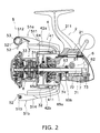
- FIG. 2 is a left side cross-sectional view of the spinning reel. It should be noted that in the following explanation, the left side in FIGS. 1 and 2 is defined as forward with respect to the spinning reel, while the right side in FIGS. 1 and 2 is defined as rearward with respect to the spinning reel.
- a spinning reel 10 includes a handle 1, a reel unit 2, a spool 3, a rotor 4 and a fishing line guide mechanism (so-called a bail arm) 5.
- the handle 1 is rotatably supported by the reel unit 2, and is attachable to either of the right and left sides of the reel unit 2.
- the reel unit 2 includes a housing 21 and a lid member 22.
- the housing 21 has an opening bored through a later part thereof.
- the lid member 22 closes the opening of the housing 21.
- the housing 21 contains an inner space to which various mechanisms are mounted.
- the housing 21 also has an attachment leg 211.
- the attachment leg 211 is a T-shaped portion that extends forwardly in an obliquely upward direction. As illustrated in FIG. 2 , a rotor drive mechanism 6 and an oscillating mechanism 7 are disposed in the inner space of the housing 21.
- the rotor drive mechanism 6 is a mechanism that is configured to rotate the rotor 4 in conjunction with rotation of the handle 1.
- the rotor drive mechanism 6 includes a drive shaft 61, a drive gear 62 and a pinion gear 63.
- the drive shaft 61 is disposed within the housing 21, and extends in the right-and-left direction of the spinning reel 10. Both ends of the drive shaft 61 are rotatably supported by the housing 21 through bearings.
- the drive shaft 61 has a female threaded portion on each ends thereof. The threaded direction and the diameter of one of the female threaded portions are different from those of the other female threaded portion.
- the handle 1 can be screwed and attached onto either one of the female threaded portions.
- the drive gear 62 is fixed onto the drive shaft 61, while being unitarily rotatable therewith.
- the drive gear 62 is made in the form of a face gear.
- the pinion gear 63 is formed in a tubular shape and is designed to be meshed with the drive gear 62.
- the pinion gear 63 is disposed within the housing 21, and extends in the back-and-front direction of the spinning reel 10.
- the front portion of the pinion gear 63 is fixed to the rotor 4 by a nut 64, while extending through the center part of the rotor 4.
- the pinion gear 63 is rotatably supported by the reel unit 2 through a pair of bearings 65a and 65b. Specifically, the axially intermediate portion of the pinion gear 63 is supported by the bearing 65a, while the axially rear end portion of the pinion gear 63 is supported by the bearing 65b.
- the oscillating mechanism 7 is a mechanism that is configured to move the spool 3 in the back-and-front direction of the spinning reel 10 in order to uniformly wind a fishing line.
- the oscillating mechanism 7 includes a spool shaft 71, a worm shaft 72, a slider 73 and an intermediate gear 74.
- the spool shaft 71 is disposed so as to extend in the back-and-front direction.
- the spool shaft 71 is disposed while extending through the center part of the pinion gear 63.
- the spool shaft 71 is allowed to be reciprocated back and forth in the inside of the pinion gear 63.
- the spool shaft 71 is supported in an axially movable state. Specifically, the intermediate portion of the spool shaft 71 is supported by a bearing 65c mounted to the inside of the nut 64, while the rear portion of the spool shaft 71 is supported by the inner peripheral surface of the rear portion of the pinion gear 63.
- the spool shaft 71 is non-rotatable, while the pinion gear 63 is rotatable relatively to the spool shaft 71. Electroless nickel plating is performed on the surface of the spool shaft 71 for preventing the spool shaft 71 from getting stuck with the pinion gear 63 when the spool shaft 71 is moved back and forth while being rotated relatively to the pinion gear 63.
- the worm shaft 72 is disposed below and parallel to the spool shaft 71.
- the slider 73 is configured to be moved back and forth along the worm shaft 72 in the back-and-front direction.
- the rear end of the spool shaft 71 is non-rotatably fixed to the slider 73.
- the intermediate gear 74 is fixed onto the tip end of the worm shaft 72, while being meshed with the pinion gear 63.
- the spool 3 is a member that the fishing line is wound onto the outer peripheral surface thereof.
- the spool 3 is disposed at the front of the reel unit 2, while being movable in the back-and-front direction.
- the spool 3 is disposed between a first rotor arm 42a and a second rotor arm 42b of the rotor 4 to be described.
- the center part of the spool 3 is coupled to the tip end of the spool shaft 71 through a drag mechanism 8.
- the spool 3 has a bobbin trunk 31, a skirt 32 and a flange 33.
- the bobbin trunk 31 is a cylindrical member that the fishing line is wound onto the outer peripheral surface thereof.
- the skirt 32 is formed in a cylindrical shape, and has a diameter larger than that of the bobbin trunk 31.
- the skirt 32 is disposed on the back of the bobbin trunk 31.
- the flange 33 is formed on the front end of the bobbin trunk 31. It should be noted that the bobbin trunk 31, the skirt 32 and the flange 33 are integrally formed.
- the rotor 4 is rotatably supported at the front of the reel unit 2.
- the rotor 4 has a cylindrical part 41, the first rotor arm 42a and the second rotor arm 42b.
- the cylindrical part 41 and the first and second rotor arms 42a and 42b are made of, for example, aluminum alloy, and are integrally formed.
- the cylindrical part 41, except for the rear end thereof, is accommodated in the skirt 32 of the spool 3.
- the cylindrical part 41 has a boss portion 411 in the inside thereof.
- the cylindrical part 41 is fixed onto the pinion gear 63 through the boss portion 411.
- the boss portion 411 has a through hole in the center part thereof.
- the pinion gear 63 extends through the through hole.
- the nut 64 is disposed at the front of the boss portion 411. The rotor 4 is fixed onto the pinion gear 63 by the nut 64.
- the first and second rotor arms 42a and 42b extend forwardly from the lateral sides of the cylindrical part 41.
- the first and second rotor arms 42a and 42b are disposed in the opposite positions with respect to the circumferential direction of the cylindrical part 41.
- FIG. 3 is a front elevational view of the spinning reel.
- FIG. 4 is a partial enlarged view of the fishing line guide mechanism 5
- FIG. 5 is a partial cross-sectional view of the fishing line guide mechanism 5.
- the fishing line guide mechanism 5 is a mechanism for guiding the fishing line onto the spool 3.
- the fishing line guide mechanism 5 is pivotally mounted to the tip ends of the first and second rotor arms 42a and 42b to pivot between a fishing-line guide position and a fishing-line release position.
- the fishing line guide mechanism 5 includes a first bail support member 51a, a second bail support member 51b, a bail 52, a stationary shaft 53, a line roller 9 and two restriction members 93a and 93b (see FIG. 5 ).
- the first bail support member 51a is pivotally mounted to the outer side of the tip end of the first rotor arm 42a.
- the second bail support member 51b is pivotally mounted to the outer side of the tip end of the second rotor arm 42b.
- the first bail support member 51a has a first end 511 and a second end 512.
- the first end 511 is pivotally mounted to the first rotor arm 42a.
- the second end 512 supports a cover portion 521 through the stationary shaft 53 and a fixation bolt 56.
- the cover portion 521 corresponds to a first end of the bail 52.
- the first bail support member 51a has a stepped through hole 513 bored in the second end 512.
- the fixation bolt 56 extends through the through hole 513 in order to fix the stationary shaft 53 to the first bail support member 51a.
- a first end 514 of the second bail support member 51b is pivotally mounted to the second rotor arm 42b, while a second end 515 of the second bail support member 51b supports a second end of the bail 52.
- the bail 52 is a roughly U-shaped member that is made of stainless alloy.
- the bail 52 is curved in an outwardly convex shape along the outer peripheral surface of the spool 3.
- the bail 52 has the cover portion 521 as the first end thereof.
- the cover portion 521 is supported by the first bail support member 51a through the stationary shaft 53 and the fixation bolt 56.
- the second end of the bail 52 is supported by the second bail support member 51b.
- the bail 52 is configured to lead the fishing line onto the line roller 9 through the cover portion 521 when the fishing line guide mechanism 5 is returned to the fishing-line guide position from the fishing-line release position.
- the stationary shaft 53 extends between the first bail support member 51a and the bail 52.
- the stationary shaft 53 has a shaft portion 531 and a head portion 532.
- the shaft portion 531 is formed in a cylindrical shape.
- the head portion 532 has a diameter larger than that of the shaft portion 531.
- a base end 5311 of the shaft portion 531 is supported by the cover portion 521 of the bail 52, while a tip end 5312 of the shaft portion 531 is supported by the second end 512 of the first bail support member 51a.
- the stationary shaft 53 has a female threaded portion formed on the inner peripheral surface of the shaft portion 531.
- the fixation bolt 56 is screwed into the female threaded portion.
- FIG. 6 is a cross-sectional view of the line roller 9.
- the line roller 9 includes a bearing member 91 and a guide member 92.
- the bearing member 91 includes a cylindrical inner race 911, a cylindrical outer race 912 and a plurality of rolling elements 913.
- the stationary shaft 53 is fitted into the inner race 911.
- the inner race 911 is firmly fixed onto the stationary shaft 53 such that relative rotation is prevented between the inner race 911 and the stationary shaft 53.
- the outer race 912 has a diameter larger than that of the cylindrical inner race 911.
- the outer race 912 is disposed on the outer peripheral side of the inner race 911.
- the rolling elements 913 are disposed between the inner race 911 and the outer race 912, while being circumferentially aligned at predetermined intervals.
- the inner race 911 and the outer race 912 are made of the same kind of metals or alloys, for example, stainless steel.
- the guide member 92 is formed in a generally cylindrical shape.
- the bearing member 91 is integrally and firmly fixed with the guide member 92 on the inner peripheral side of the guide member 92. Specifically, the bearing member 91 is press fitted into the guide member 92. Accordingly, the guide member 92 unitarily rotates with the outer race 912.
- the guide member 92 is preferably made of metal or alloy having the same ionization tendency as that of the outer race 912.
- the guide member 92 is made of stainless steel of which the outer race 912 is made.
- the outer peripheral surface of the guide member 92 is formed as a guide surface 921 for guiding the fishing line.
- the guide surface 921 has a circumferentially extending annular recess 922 on the center part thereof. It should be noted that the recess 922 is formed in a position offset from the center of the guide surface 921 towards the cover portion 521. To lead the fishing line to the recess 922, the guide surface 921 is slanted from the both ends thereof towards the recess 922.
- the guide member 92 has a first protruded portion 923a and a second protruded portion 923b.
- the first protruded portion 923a is a portion that axially protrudes more towards the cover portion 521 (i.e., leftward in FIG. 6 ) in comparison with the outer race 912.
- the first protruded portion 923a is formed in an annular shape, and is concentric to the stationary shaft 53.
- the second protruded portion 923b is a portion that axially protrudes more towards the second end 512 of the first bail support member 51a (i.e., rightward in FIG. 6 ) in comparison with the bearing member 91.
- the second protruded portion 923b is formed in an annular shape, and is concentric to the stationary shaft 53.
- the line roller 9 can further include the first and second restriction members 93a and 93b.
- the first and second restriction members 93a and 93b are formed in a cylindrical shape, and are supported by the stationary shaft 53.
- the first and second restriction members 93 and 93b are disposed so as to interpose the bearing member 91 therebetween.
- the first restriction member 93a is disposed between the cover portion 521 and the bearing member 91.
- the second restriction member 93b is disposed between the second end 512 of the first bail support member 51a and the bearing member 91.
- the fixation bolt 56 is screwed and tightened into the female threaded portion formed on the inner peripheral surface of the shaft portion 531 of the stationary shaft 53. Accordingly, the first and second restriction members 93a and 93b are fixed, while being interposed and held in the aforementioned positions.
- the first and second restriction members 93a and 93b restrict the line roller 9 from axially moving to a large amount.
- first and second restriction members 93a and 93b are larger than or equal to the outer diameter of the stationary shaft 53. Further, the outer diameters of the first and second restriction members 93a and 93b are larger than the outer diameter of the inner race of the bearing member 91.
- the rotor 4 is set in the reverse rotation prevented state, and the fishing line guide mechanism 5 is flipped over to the fishing-line release position while being held by the angler's hand.
- the fishing line can be easily reeled out of the spool 3 under the condition that the fishing line guide mechanism 5 is pivoted down to the fishing-line release position.
- the rotor drive mechanism 6 causes the rotor 4 to rotate in the fishing-line winding direction.
- the fishing line guide mechanism 5 is returned to the fishing-line guide position.
- the fishing line is led to the line roller 9 from the bail 52 through the cover portion 521, and is wound about the spool 3.
- the line roller 9 according to the present exemplary embodiment has the following features.
- the line roller 9 is a member for guiding the fishing line onto the spool 3 of the spinning reel 10.
- the line roller 9 includes the bearing member 91 and the guide member 92.
- the bearing member 91 includes the cylindrical inner race 911, the cylindrical outer race 912 disposed on the outer peripheral side of the inner race 911, and the rolling elements 913 that are disposed between the inner race 911 and the outer race 912 while being circumferentially aligned at intervals.
- the guide member 92 is made of material of the same kind as that of the outer race 912. Further, the guide member 92 is a tubular member having the guide surface 921 on the outer peripheral surface thereof in order to guide the fishing line. The guide member 92 is firmly fixed to the bearing member 91 on the outer peripheral surface of the bearing member 91.
- the bearing member 91 and the guide member 92 are produced as separate members. Therefore, even when the guide surface 921 as the outer peripheral surface of the guide member 92 is processed, this does not negatively affect smoothness in rotation of the bearing member 91. Further, the guide member 92 is directly and firmly fixed to the bearing member 91. Therefore, the line roller 9 is smoothly rotated. It should be noted that occurrence of galvanic corrosion can be suppressed between the guide member 92 and the bearing member 91, although the guide member 92 is directly and firmly fixed to the bearing member 91. This is due to the fact that the guide member 92 and the bearing member 91 are made of the same kind of materials.
- the inner race 911, the outer race 912 and the guide member 92 are made of the same kind of materials. According to the structure, occurrence of galvanic corrosion can be further suppressed among these elements.
- the guide member 92 has the annular recess 922 extending circumferentially on the guide surface 921. According to the structure, the fishing line can be guided to the spool 3 with use of the recess 922 formed on the guide surface 921.
- the guide member 92 and the outer race 912 are made of metals or alloys having the same ionization tendency. According to the structure, occurrence of galvanic corrosion can be suppressed between these elements.
- the guide member 92 is integrally and firmly fixed to the outer race 912 when the outer race 912 is press fitted into the guide member 92. According to the structure, the guide member 92 can be easily and firmly fixed onto the outer race 912.
- a line roller 9 according to the aforementioned exemplary embodiment can be alternatively structured as illustrated in FIG. 7 .
- a line roller 9a according to a first modification further includes a first seal member 94a and a second seal member 94b.
- the first and second seal members 94a and 94b are annular members made of material with elasticity, and serve to prevent water and so forth from entering the bearing member 91.
- the first and second seal members 94a and 94b may be preferably made of synthetic rubber, natural rubber, or so forth, and may be specifically made of NBR (Nitril-Butadiene Rubber, which is a copolymer of butadiene and acrylonitrile) or so forth.
- the first seal member 94a is disposed on the left side of the bearing member 91, while the second seal member 94b is disposed on the right side of the bearing member 91.
- An outer peripheral side end 941a of the first seal member 94a is attached to an inner peripheral surface 9231a of the first protruded portion 923a.
- the first seal member 94a has a first lip part 943a at the inner peripheral side thereof.
- the first lip part 943a is formed to become thinner toward the inner periphery.
- the first lip part 943a slants away from the bearing member 91 toward the inner periphery.
- An inner peripheral end 942a of the first lip part 943a contacts the outer peripheral surface of the first restriction member 93a.
- an annular groove is formed on the inner peripheral surface 9231a of the first protruded portion 923a so as to extend circumferentially thereon.
- the outer peripheral end 941a of the first seal member 94a is fitted into the annular groove. Accordingly, the first seal member 94a is configured to be attached to the first protruded portion 923a. Further, the inner peripheral end 942a of the first seal member 94a presses the outer peripheral surface of the first restriction member 93a to the extent that water can be prevented from entering from the side with the bearing member 91.
- An outer peripheral end 941b of the second seal member 94b is attached to an inner peripheral surface 9231b of the second protruded portion 923b.
- the second seal member 94b has a second lip part 943b at the inner peripheral side thereof.
- the second lip part 943b is formed to become thinner toward the inner periphery.
- the second lip part 943b slants away from the bearing member 91 toward the inner periphery.
- An inner peripheral end 942b of the second lip part 943b contacts the outer peripheral surface of the second restriction member 93b.
- an annular groove is formed on the inner peripheral surface 9231B of the second protruded portion 923b so as to extend circumferentially thereon.
- the outer peripheral end 941b of the second seal member 94b is fitted into the annular groove. Accordingly, the second seal member 94b is allowed to be attached to the second protruded portion 923b. Further, the inner peripheral end 942b of the second seal member 94b presses the outer peripheral surface of the second restriction member 93b to the extent that water can be prevented from entering from the side with the bearing member 91.
- the outer peripheral surfaces of the first and second restriction members 93a and 93b preferably have water repellency.
- a contact angle of 90 degrees or greater is formed by the outer peripheral surface thereof and a water droplet attached to the outer peripheral surface.
- the following may be performed for applying water repellency to the outer peripheral surfaces of the first and second restriction members 93a and 93b.
- material with water repellency may be applied to the outer peripheral surfaces of the first and second restriction members 93a and 93b.
- the first and second restriction members 93a and 93b may be made of material with water repellency.
- the material with water repellency is, for example, material containing fluorine resin, silicone resin or so forth.
- the line roller 9a according to the first modification as explained above has the following features.
- the line roller 9a is a component for guiding the fishing line onto the spool 3 of the spinning reel 10.
- the line roller 9a includes the bearing member 91, the guide member 92 and the first and second seal members 94a and 94b.
- the bearing member 91 includes the cylindrical inner race 911, the cylindrical outer race 912 disposed on the outer peripheral side of the inner race 911, and the rolling elements 913 that are disposed between the inner race 911 and the outer race 912 while being circumferentially aligned at intervals.
- the guide member 92 is formed in a tubular shape, and has the guide surface 921 on the outer peripheral surface in order to guide the fishing line.
- the guide member 92 is integrally and firmly fixed to the bearing member 91 on the outer peripheral surface of the bearing member 91.
- the guide member 92 has a first protruded portion 923a and a second protruded portion 923b.
- the first and second protruded portions 923a and 923b are axially protruded in comparison with the outer race 912.
- the first seal member 94a is an annular member that extends radially inwards from the inner peripheral surface 9231a of the first protruded portion 923a.
- the second seal member 94b is an annular member that extends radially inwards from the inner peripheral surface 9231b of the second protruded portion 923b.
- the annular first seal member 94a is mounted so as to extend radially inwards from the inner peripheral surface 9231a of the first protruded portion 923a of the guide member 92. Therefore, the axially lateral surface of the bearing member 91 can be covered with the first seal member 94a on the side with the cover portion 521.
- the annular second seal member 94b is mounted so as to extend radially inwards form the inner peripheral surface 9231b of the second protruded portion 923b of the guide member 92.
- the axially lateral surface of the bearing member 91 can be covered with the second seal member 94b on the side with the first bail support member 51a. As a result, it is possible to prevent troubles such as water intrusion into the bearing member 91 by the first and second seal members 94a and 94b.
- the line roller 9a according to the first modification further includes the first and second restriction members 93a and 93b that are cylindrically formed and disposed adjacently to the bearing member 91 in the axial direction.
- the inner peripheral end 942a of the first seal member 94a contacts the outer peripheral surface of the first restriction member 93a.
- the inner peripheral end 942b of the second seal member 94b contacts the outer peripheral surface of the second restriction member 93b.
- the lateral surface of the bearing member 91 on the cover portion 521 side can be covered with the first seal member 94a that extends between the first protruded portion 923a and the first restriction member 93a.
- the lateral surface of the bearing member 91 on the first bail support member 51a side can be covered with the second seal member 94b that extends between the second protruded portion 923b and the second restriction member 93b.
- the outer peripheral surfaces of the first and second restriction members 93a and 93b according to the first modification have water repellency. According to the structure, water is repelled by the outer peripheral surfaces of the first and second restriction members 93a and 93b. Therefore, it is possible to more reliably prevent water intrusion into the bearing member 91.
- FIG. 8 is a cross-sectional view of a line roller 9b according to a second modification.
- the first and second protruded portions 923a and 923b of the guide member 92 are formed on the radially outer peripheral side.
- the positions where the first and second protruded portions 923a and 923b are formed are not particularly limited to the above.
- the first and second protruded portions 923a and 923b can be entirely formed in the radial direction.
- the first and second protruded portions 923a and 923b may be formed on the radially inner side.
- FIG. 9 is a cross-sectional view of a line roller 9c according to a third modification.
- the inner peripheral end 942a of the first seal member 94a contacts the first restriction member 93a
- the inner peripheral end 942b of the second seal member 94b contacts the second restriction member 93b.
- the structure of the line roller of the present invention is not limited to the above.
- the bearing member 91 can be designed to have a structure that the axial length of the inner race 911 is longer than that of the outer race 912.
- the inner peripheral end 942a of the first seal member 94a and the inner peripheral end 942b of the second seal member 94b can be designed to contact the outer peripheral surface of the inner race 911.
- FIG. 10 is a cross-section view of a line roller 9d according a fourth modification.
- the inner peripheral end 942a of the first seal member 94a contacts the first restriction member 93a and the inner peripheral end 942b of the second seal member 94b contacts the second restriction member 93b.
- the structure of the line roller of the present invention is not limited to the above.
- the first seal member 94a can be configured not to contact the first restriction member 93a.
- the inner peripheral end 942a of the first seal member 94a faces the outer peripheral surface of the first restriction member 93a with an interval.
- the distance between the inner peripheral end 942a of the first seal member 94a and the outer peripheral surface of the first restriction member 93a is preferably around 0.05 mm to 0.3 mm, more preferably around 0.1 mm to 0.2mm.
- At least one of the inner peripheral end 942a of the first seal member 94a and the outer peripheral surface of the first restriction member 93a has water repellency.
- the second seal member 94b can be configured not to contact the second restriction member 93b.
- the inner peripheral end 942b of the second seal member 94b faces the outer peripheral surface of the second restriction member 93b with an interval.
- the distance between the inner peripheral end 942b of the second seal member 94b and the outer peripheral surface of the second restriction member 93b is preferably around 0.05 mm to 0.3 mm, more preferably around 0.1 mm to 0.2mm.
- At least one of the inner peripheral end 942b of the second seal member 94b and the outer peripheral surface of the second restriction member 93b has water repellency.
- the outer peripheral surface of the first restriction member 93a and the outer peripheral surface of the second restriction member 93b have water repellency in terms of in terms of aging, an effect of an external environment, and easy water repellent processing.
- the inner peripheral surface of the guide member 92 and the outer peripheral surface of the outer race 912 can be adhered to each other by an adhesive or so forth.
- the bearing member 91 may or may not be fitted into the guide member 92.
- a surface treated layer may be formed at least on the guide surface 921 of the guide member 92 by surface treating.
- a surface treated layer made of DLC (Diamond-Like Carbon) or so forth can be formed at least on the guide surface 921 of the guide member 92 by means of a CVD method, a PVD method or so forth.
- IP Ion Plating
- any suitable surface treating is preferably performed for the guide member 92 before the guide member 92 is firmly fixed onto the bearing member 91. Accordingly, surface treating can be performed only for the guide member 92 without being performed for the bearing member 91. As a result, deterioration in rotational smoothness of the bearing member 91 can be prevented.
- the outer race 912 of the bearing member 91 and the guide member 92 are made of metals or alloys having the same ionization tendency.
- the ionization tendencies of the metals or alloys may not be completely the same as long as they are the same to the extent that occurrence of galvanic corrosion can be prevented.
Landscapes
- Life Sciences & Earth Sciences (AREA)
- Environmental Sciences (AREA)
- Animal Husbandry (AREA)
- Biodiversity & Conservation Biology (AREA)
Abstract
Description
- This application claims priority to Japanese Patent Applications Nos.
2013-88336 filed on April 19, 2013 2013-88337 filed on April 19, 2013 2013-257607 filed on December 13, 2013 - The present invention relates to a line roller and a fishing line guide mechanism using the same.
- A spinning reel includes a spool, a rotor having a pair of rotor arms, and a fishing line guide mechanism (so-called a bail arm mechanism) pivotally mounted to the tip ends of the pair of the rotor arms. The fishing line guide mechanism is a mechanism for guiding a fishing line onto the spool. The fishing line guide mechanism is mainly composed of a bail, a pair of bail support members for supporting the both ends of the bail, and a line roller. The line roller is generally mounted to a bearing through a bushing. For example, Japanese Laid-Open Patent Application Publication No.
JP-A-H04-316443 - It has been discovered that certain drawbacks exists in the aforementioned line roller that has a structure with a recess on an outer peripheral surface of an outer race of the bearing. For example, when the recess is formed on the outer race of the bearing, this inevitably poses negative impact on, for example, contact between the outer race and rolling elements. As a result, chances are that smoothness in rotation of the bearing will likely deteriorate.
- It is an object of the present invention to provide a line roller that more smoothly rotates for guiding a fishing line onto a spool of a spinning reel.
- A line roller according to a first aspect of the present invention is provided for guiding a fishing line onto a spool of a spinning reel. The line roller includes a bearing member and a guide member. The bearing member includes an inner race, an outer race and a plurality of rolling elements. The inner race has a cylindrical shape. The outer race has a cylindrical shape, and is disposed on an outer peripheral side of the inner race. The rolling elements are circumferentially aligned at intervals between the inner race and the outer race. The guide member has a tubular shape. The guide member is made of a material of the same kind as a material of the outer race. The guide member has a guide surface for guiding the fishing line on an outer peripheral surface of the guide member. Further, the guide member is firmly fixed to the bearing member on an outer peripheral surface of the bearing member.
- According to the structure, the bearing member and the guide member are provided as separate members. Therefore, even when the guide surface, which is the outer peripheral surface of the guide member, is processed, this does not negatively affect smoothness in rotation of the bearing member. Further, the guide member is directly and firmly fixed onto the bearing member. Therefore, the line roller is smoothly rotated. It should be noted that occurrence of galvanic corrosion can be suppressed between the guide member and the bearing member, although the guide member is directly and firmly fixed onto the bearing member. This is due to the fact that the guide member and the bearing member are made of the same kind of materials.
- Preferably, the line roller further includes a seal member having an annular shape. Preferably, the guide member further has a protruded portion that protrudes axially more than the outer race in an axial direction of the bearing member. Preferably, the seal member extends radially inwards from an inner peripheral surface of the protruded portion with respect to the axial direction of the bearing member.
- According to the structure, the annular seal member is disposed so as to extend radially inwards from the inner peripheral surface of the protruded portion of the guide member. Therefore, an axially lateral surface of the bearing can be covered with the seal member. As a result, it is possible to prevent troubles such as water intrusion into the bearing member by the seal member.
- Preferably, the line roller further includes a restriction member having a cylindrical shape and that is disposed axially adjacent to the bearing member. Preferably, the seal member extends toward an outer peripheral surface of the restriction member. According to the structure, an axially lateral surface of the bearing can be covered with the seal member that extends between the protruded portion and the restriction member. Therefore, it is possible to prevent troubles such as water intrusion into the bearing member.
- Preferably, an inner peripheral of the seal member faces the outer peripheral surface of the restriction member with a gap between the inner peripheral end of the seal member and the outer peripheral surface of the restriction member. At least one of the inner peripheral end of the seal member and the outer peripheral surface of the restriction member has water repellency. According to the structure, the seal member and the restriction member do not make contact with each other. Therefore, this does not negatively affect smoothness in rotation of the bearing. Further, at least one of the inner peripheral end of the seal member and the outer peripheral surface of the restriction member has water repellency. Therefore, it is possible to prevent water intrusion into the bearing member even though there is a gap between the seal member and the restriction member. It is more preferable that the outer peripheral surface of the restriction member has water repellency in terms of aging, an effect of an external environment, and easy water repellent processing.
- Alternatively, the inner peripheral end of the seal member may contact the outer peripheral surface of the restriction member.
- Preferably, at least one of the inner peripheral end of the seal member and the outer peripheral surface of the restriction member has water repellency. According to the structure, water is repelled by at least one of the inner peripheral end of the seal member and the outer peripheral surface of the restriction member. Therefore, it is possible to more reliably prevent water intrusion into the bearing member. It is more preferable that the outer peripheral surface of the restriction member has water repellency in terms of aging, an effect of an external environment, and easy water repellent processing.
- Preferably, the inner race of the bearing member has an axial length larger than an axial length of the outer race. Further, the seal member preferably has an inner peripheral end that contacts an outer peripheral surface of the inner race. According to the structure, an axially lateral surface of the bearing member can be covered with the seal member that extends between the protruded portion and the inner race. Therefore, it is possible to prevent troubles such as water intrusion into the bearing member.
- Preferably, the inner race, the outer race and the guide member are made of the same kind of materials. According to the structure, occurrence of galvanic corrosion can be further suppressed.
- Preferably, the guide surface of the guide member has a circumferentially extending annular recess. According to the structure, the fishing line can be guided onto the spool using the recess formed on the guide surface.
- Preferably, the guide member and the outer race are made of metals or alloys having the same ionization tendency. According to the structure, occurrence of galvanic corrosion can be suppressed.
- Preferably, the outer race and the guide member are made of stainless steel.
- Preferably, the guide member is press fitted onto the outer race. According to the structure, the guide member can be easily and firmly fixed onto the outer race.
- Preferably, the guide member has an inner peripheral surface adhered onto an outer peripheral surface of the outer race. According to the structure, the guide member can be more reliably and firmly fixed onto the outer race.
- Preferably, the guide member has a surface treated layer at least on the guide surface. The surface treated layer is formed by surface treating. According to the structure, it is possible to achieve enhancement in a variety of features such as enhancement in durability of the guide surface and reduction in frictional resistance with the fishing line. Further, the guide member and the bearing member are provided as separate members. Therefore, surface treating can be easily performed only for the guide member.
- A fishing line guide mechanism according to a second aspect of the present invention is provided with the line roller discussed above for guiding a fishing line onto a spool of a spinning reel. The fishing line guide mechanism is mounted to tip ends of a pair of rotor arms of a rotor of the spinning reel. The fishing line guide mechanism further includes a bail, a first bail support member, a second bail support member and a stationary shaft. The first bail support member is configured to be mounted to the tip end of one of the rotor arms and supports a first end of the bail. The second bail support member is configured to be mounted to the tip end of the other of the rotor arms and supports a second end of the bail. The stationary shaft extends between the first bail support member and the first end of the bail. The line roller is rotatably supported by the stationary shaft.
- According to the present invention, it is possible to provide a line roller that can be more smoothly rotated.
- Referring now to the attached drawings which form a part of this original disclosure:
-
FIG. 1 is a left side elevational view of a spinning reel in accordance with a first illustrative embodiment; -
FIG. 2 is a left side cross-sectional view of the spinning reel illustrated inFIG. 1 ; -
FIG. 3 is a front elevational view of the spinning reel illustrated inFIGS. 1 and2 ; -
FIG. 4 is a partial enlarged view of a fishing line guide mechanism of the spinning reel illustrated inFIGS. 1-3 ; -
FIG. 5 is a partial enlarged cross-sectional view of the fishing line guide mechanism illustrated inFIG. 4 ; -
FIG. 6 is a further enlarged cross-sectional view of a line roller of the fishing line guide mechanism illustrated inFIG. 5 ; -
FIG. 7 is a cross-sectional view of a line roller according to a first modification; -
FIG. 8 is a cross-sectional view of a line roller according to a second modification; and -
FIG. 9 is a cross-sectional view of a line roller according to a third modification; and -
FIG. 10 is a cross-sectional view of a line roller according to a fourth modification. - With reference to the attached drawings, explanation will be hereinafter made for a line roller and a fishing line guide mechanism using the same according to an exemplary embodiment of the present invention.
FIG. 1 is a left side elevational view of the spinning reel, whereasFIG. 2 is a left side cross-sectional view of the spinning reel. It should be noted that in the following explanation, the left side inFIGS. 1 and2 is defined as forward with respect to the spinning reel, while the right side inFIGS. 1 and2 is defined as rearward with respect to the spinning reel. - As illustrated in
FIGS. 1 and2 , a spinningreel 10 includes ahandle 1, areel unit 2, aspool 3, arotor 4 and a fishing line guide mechanism (so-called a bail arm) 5. Thehandle 1 is rotatably supported by thereel unit 2, and is attachable to either of the right and left sides of thereel unit 2. - The
reel unit 2 includes ahousing 21 and alid member 22. Thehousing 21 has an opening bored through a later part thereof. Thelid member 22 closes the opening of thehousing 21. Thehousing 21 contains an inner space to which various mechanisms are mounted. Thehousing 21 also has anattachment leg 211. Theattachment leg 211 is a T-shaped portion that extends forwardly in an obliquely upward direction. As illustrated inFIG. 2 , arotor drive mechanism 6 and anoscillating mechanism 7 are disposed in the inner space of thehousing 21. - The
rotor drive mechanism 6 is a mechanism that is configured to rotate therotor 4 in conjunction with rotation of thehandle 1. Therotor drive mechanism 6 includes adrive shaft 61, adrive gear 62 and apinion gear 63. - The
drive shaft 61 is disposed within thehousing 21, and extends in the right-and-left direction of the spinningreel 10. Both ends of thedrive shaft 61 are rotatably supported by thehousing 21 through bearings. Thedrive shaft 61 has a female threaded portion on each ends thereof. The threaded direction and the diameter of one of the female threaded portions are different from those of the other female threaded portion. Thehandle 1 can be screwed and attached onto either one of the female threaded portions. Thedrive gear 62 is fixed onto thedrive shaft 61, while being unitarily rotatable therewith. Thedrive gear 62 is made in the form of a face gear. - The
pinion gear 63 is formed in a tubular shape and is designed to be meshed with thedrive gear 62. Thepinion gear 63 is disposed within thehousing 21, and extends in the back-and-front direction of the spinningreel 10. The front portion of thepinion gear 63 is fixed to therotor 4 by anut 64, while extending through the center part of therotor 4. Further, thepinion gear 63 is rotatably supported by thereel unit 2 through a pair ofbearings pinion gear 63 is supported by thebearing 65a, while the axially rear end portion of thepinion gear 63 is supported by thebearing 65b. - The
oscillating mechanism 7 is a mechanism that is configured to move thespool 3 in the back-and-front direction of the spinningreel 10 in order to uniformly wind a fishing line. Theoscillating mechanism 7 includes aspool shaft 71, aworm shaft 72, aslider 73 and anintermediate gear 74. - The
spool shaft 71 is disposed so as to extend in the back-and-front direction. Thespool shaft 71 is disposed while extending through the center part of thepinion gear 63. Thespool shaft 71 is allowed to be reciprocated back and forth in the inside of thepinion gear 63. Thespool shaft 71 is supported in an axially movable state. Specifically, the intermediate portion of thespool shaft 71 is supported by abearing 65c mounted to the inside of thenut 64, while the rear portion of thespool shaft 71 is supported by the inner peripheral surface of the rear portion of thepinion gear 63. It should be noted that thespool shaft 71 is non-rotatable, while thepinion gear 63 is rotatable relatively to thespool shaft 71. Electroless nickel plating is performed on the surface of thespool shaft 71 for preventing thespool shaft 71 from getting stuck with thepinion gear 63 when thespool shaft 71 is moved back and forth while being rotated relatively to thepinion gear 63. - The
worm shaft 72 is disposed below and parallel to thespool shaft 71. Theslider 73 is configured to be moved back and forth along theworm shaft 72 in the back-and-front direction. The rear end of thespool shaft 71 is non-rotatably fixed to theslider 73. Theintermediate gear 74 is fixed onto the tip end of theworm shaft 72, while being meshed with thepinion gear 63. - The
spool 3 is a member that the fishing line is wound onto the outer peripheral surface thereof. Thespool 3 is disposed at the front of thereel unit 2, while being movable in the back-and-front direction. When explained in more detail, as illustrated inFIGS. 1 and2 , thespool 3 is disposed between afirst rotor arm 42a and asecond rotor arm 42b of therotor 4 to be described. Further, the center part of thespool 3 is coupled to the tip end of thespool shaft 71 through adrag mechanism 8. Thespool 3 has abobbin trunk 31, askirt 32 and aflange 33. Thebobbin trunk 31 is a cylindrical member that the fishing line is wound onto the outer peripheral surface thereof. Theskirt 32 is formed in a cylindrical shape, and has a diameter larger than that of thebobbin trunk 31. Theskirt 32 is disposed on the back of thebobbin trunk 31. Theflange 33 is formed on the front end of thebobbin trunk 31. It should be noted that thebobbin trunk 31, theskirt 32 and theflange 33 are integrally formed. - The
rotor 4 is rotatably supported at the front of thereel unit 2. As illustrated inFIG. 2 , therotor 4 has acylindrical part 41, thefirst rotor arm 42a and thesecond rotor arm 42b. Thecylindrical part 41 and the first andsecond rotor arms cylindrical part 41, except for the rear end thereof, is accommodated in theskirt 32 of thespool 3. Further, thecylindrical part 41 has aboss portion 411 in the inside thereof. Thecylindrical part 41 is fixed onto thepinion gear 63 through theboss portion 411. When explained in detail, theboss portion 411 has a through hole in the center part thereof. Thepinion gear 63 extends through the through hole. Thenut 64 is disposed at the front of theboss portion 411. Therotor 4 is fixed onto thepinion gear 63 by thenut 64. - The first and
second rotor arms cylindrical part 41. The first andsecond rotor arms cylindrical part 41. -
FIG. 3 is a front elevational view of the spinning reel.FIG. 4 is a partial enlarged view of the fishingline guide mechanism 5, whereasFIG. 5 is a partial cross-sectional view of the fishingline guide mechanism 5. As illustrated inFIGS. 1 to 3 , the fishingline guide mechanism 5 is a mechanism for guiding the fishing line onto thespool 3. The fishingline guide mechanism 5 is pivotally mounted to the tip ends of the first andsecond rotor arms line guide mechanism 5 includes a firstbail support member 51a, a secondbail support member 51b, abail 52, astationary shaft 53, aline roller 9 and tworestriction members FIG. 5 ). - The first
bail support member 51a is pivotally mounted to the outer side of the tip end of thefirst rotor arm 42a. The secondbail support member 51b is pivotally mounted to the outer side of the tip end of thesecond rotor arm 42b. As illustrated inFIG. 4 , the firstbail support member 51a has afirst end 511 and asecond end 512. Thefirst end 511 is pivotally mounted to thefirst rotor arm 42a. Thesecond end 512 supports acover portion 521 through thestationary shaft 53 and afixation bolt 56. Thecover portion 521 corresponds to a first end of thebail 52. - As illustrated in
FIG. 5 , the firstbail support member 51a has a stepped throughhole 513 bored in thesecond end 512. Thefixation bolt 56 extends through the throughhole 513 in order to fix thestationary shaft 53 to the firstbail support member 51a. On the other hand, as illustrated inFIGS. 1 and2 , afirst end 514 of the secondbail support member 51b is pivotally mounted to thesecond rotor arm 42b, while asecond end 515 of the secondbail support member 51b supports a second end of thebail 52. - As illustrated in
FIG. 3 , thebail 52 is a roughly U-shaped member that is made of stainless alloy. Thebail 52 is curved in an outwardly convex shape along the outer peripheral surface of thespool 3. Thebail 52 has thecover portion 521 as the first end thereof. Thecover portion 521 is supported by the firstbail support member 51a through thestationary shaft 53 and thefixation bolt 56. On the other hand, the second end of thebail 52 is supported by the secondbail support member 51b. Thebail 52 is configured to lead the fishing line onto theline roller 9 through thecover portion 521 when the fishingline guide mechanism 5 is returned to the fishing-line guide position from the fishing-line release position. - As illustrated in
FIG. 5 , thestationary shaft 53 extends between the firstbail support member 51a and thebail 52. When explained in more detail, thestationary shaft 53 has ashaft portion 531 and ahead portion 532. Theshaft portion 531 is formed in a cylindrical shape. Thehead portion 532 has a diameter larger than that of theshaft portion 531. Abase end 5311 of theshaft portion 531 is supported by thecover portion 521 of thebail 52, while atip end 5312 of theshaft portion 531 is supported by thesecond end 512 of the firstbail support member 51a. Thestationary shaft 53 has a female threaded portion formed on the inner peripheral surface of theshaft portion 531. Thefixation bolt 56 is screwed into the female threaded portion. -
FIG. 6 is a cross-sectional view of theline roller 9. As illustrated inFIG. 6 , theline roller 9 includes a bearingmember 91 and aguide member 92. The bearingmember 91 includes a cylindricalinner race 911, a cylindricalouter race 912 and a plurality of rollingelements 913. Thestationary shaft 53 is fitted into theinner race 911. In other words, theinner race 911 is firmly fixed onto thestationary shaft 53 such that relative rotation is prevented between theinner race 911 and thestationary shaft 53. Theouter race 912 has a diameter larger than that of the cylindricalinner race 911. Theouter race 912 is disposed on the outer peripheral side of theinner race 911. The rollingelements 913 are disposed between theinner race 911 and theouter race 912, while being circumferentially aligned at predetermined intervals. Theinner race 911 and theouter race 912 are made of the same kind of metals or alloys, for example, stainless steel. - The
guide member 92 is formed in a generally cylindrical shape. The bearingmember 91 is integrally and firmly fixed with theguide member 92 on the inner peripheral side of theguide member 92. Specifically, the bearingmember 91 is press fitted into theguide member 92. Accordingly, theguide member 92 unitarily rotates with theouter race 912. Theguide member 92 is preferably made of metal or alloy having the same ionization tendency as that of theouter race 912. For example, theguide member 92 is made of stainless steel of which theouter race 912 is made. - The outer peripheral surface of the
guide member 92 is formed as aguide surface 921 for guiding the fishing line. Specifically, theguide surface 921 has a circumferentially extendingannular recess 922 on the center part thereof. It should be noted that therecess 922 is formed in a position offset from the center of theguide surface 921 towards thecover portion 521. To lead the fishing line to therecess 922, theguide surface 921 is slanted from the both ends thereof towards therecess 922. - Further, the
guide member 92 has a first protrudedportion 923a and a second protrudedportion 923b. The first protrudedportion 923a is a portion that axially protrudes more towards the cover portion 521 (i.e., leftward inFIG. 6 ) in comparison with theouter race 912. The first protrudedportion 923a is formed in an annular shape, and is concentric to thestationary shaft 53. On the other hand, the second protrudedportion 923b is a portion that axially protrudes more towards thesecond end 512 of the firstbail support member 51a (i.e., rightward inFIG. 6 ) in comparison with the bearingmember 91. The second protrudedportion 923b is formed in an annular shape, and is concentric to thestationary shaft 53. - Moreover, as illustrated in
FIG. 5 , theline roller 9 can further include the first andsecond restriction members second restriction members stationary shaft 53. The first andsecond restriction members 93 and 93b are disposed so as to interpose the bearingmember 91 therebetween. - Specifically, the
first restriction member 93a is disposed between thecover portion 521 and the bearingmember 91. On the other hand, thesecond restriction member 93b is disposed between thesecond end 512 of the firstbail support member 51a and the bearingmember 91. Further, thefixation bolt 56 is screwed and tightened into the female threaded portion formed on the inner peripheral surface of theshaft portion 531 of thestationary shaft 53. Accordingly, the first andsecond restriction members second restriction members line roller 9 from axially moving to a large amount. It should be noted that the inner diameters of the first andsecond restriction members stationary shaft 53. Further, the outer diameters of the first andsecond restriction members member 91. - Next, operations and actions of the reel will be hereinafter explained in detail. In casting, the
rotor 4 is set in the reverse rotation prevented state, and the fishingline guide mechanism 5 is flipped over to the fishing-line release position while being held by the angler's hand. The fishing line can be easily reeled out of thespool 3 under the condition that the fishingline guide mechanism 5 is pivoted down to the fishing-line release position. - After casting, when the
handle 1 is rotated in the fishing-line winding direction under the condition that the fishingline guide mechanism 5 is kept set in the fishing-line release position, therotor drive mechanism 6 causes therotor 4 to rotate in the fishing-line winding direction. When therotor 4 is rotated in the fishing-line winding direction, the fishingline guide mechanism 5 is returned to the fishing-line guide position. When thehandle 1 is herein further rotated in the fishing-line winding direction, the fishing line is led to theline roller 9 from thebail 52 through thecover portion 521, and is wound about thespool 3. - The
line roller 9 according to the present exemplary embodiment has the following features. - The
line roller 9 according to the present exemplary embodiment is a member for guiding the fishing line onto thespool 3 of the spinningreel 10. Theline roller 9 includes the bearingmember 91 and theguide member 92. The bearingmember 91 includes the cylindricalinner race 911, the cylindricalouter race 912 disposed on the outer peripheral side of theinner race 911, and the rollingelements 913 that are disposed between theinner race 911 and theouter race 912 while being circumferentially aligned at intervals. Theguide member 92 is made of material of the same kind as that of theouter race 912. Further, theguide member 92 is a tubular member having theguide surface 921 on the outer peripheral surface thereof in order to guide the fishing line. Theguide member 92 is firmly fixed to the bearingmember 91 on the outer peripheral surface of the bearingmember 91. - According to the structure, the bearing
member 91 and theguide member 92 are produced as separate members. Therefore, even when theguide surface 921 as the outer peripheral surface of theguide member 92 is processed, this does not negatively affect smoothness in rotation of the bearingmember 91. Further, theguide member 92 is directly and firmly fixed to the bearingmember 91. Therefore, theline roller 9 is smoothly rotated. It should be noted that occurrence of galvanic corrosion can be suppressed between theguide member 92 and the bearingmember 91, although theguide member 92 is directly and firmly fixed to the bearingmember 91. This is due to the fact that theguide member 92 and the bearingmember 91 are made of the same kind of materials. - The
inner race 911, theouter race 912 and theguide member 92 are made of the same kind of materials. According to the structure, occurrence of galvanic corrosion can be further suppressed among these elements. - The
guide member 92 has theannular recess 922 extending circumferentially on theguide surface 921. According to the structure, the fishing line can be guided to thespool 3 with use of therecess 922 formed on theguide surface 921. - The
guide member 92 and theouter race 912 are made of metals or alloys having the same ionization tendency. According to the structure, occurrence of galvanic corrosion can be suppressed between these elements. - The
guide member 92 is integrally and firmly fixed to theouter race 912 when theouter race 912 is press fitted into theguide member 92. According to the structure, theguide member 92 can be easily and firmly fixed onto theouter race 912. - An exemplary embodiment of the present invention has been described above. However, the present invention is not limited to the exemplary embodiment, and a variety of changes can be herein made without departing from the scope of the present invention.
- The
line roller 9 according to the aforementioned exemplary embodiment can be alternatively structured as illustrated inFIG. 7 . Specifically, unlike theline roller 9 according to the aforementioned exemplary embodiment, aline roller 9a according to a first modification further includes afirst seal member 94a and asecond seal member 94b. - The first and
second seal members member 91. For example, the first andsecond seal members first seal member 94a is disposed on the left side of the bearingmember 91, while thesecond seal member 94b is disposed on the right side of the bearingmember 91. - An outer
peripheral side end 941a of thefirst seal member 94a is attached to an innerperipheral surface 9231a of the first protrudedportion 923a. Thefirst seal member 94a has afirst lip part 943a at the inner peripheral side thereof. Thefirst lip part 943a is formed to become thinner toward the inner periphery. Thefirst lip part 943a slants away from the bearingmember 91 toward the inner periphery. An innerperipheral end 942a of thefirst lip part 943a contacts the outer peripheral surface of thefirst restriction member 93a. For example, an annular groove is formed on the innerperipheral surface 9231a of the first protrudedportion 923a so as to extend circumferentially thereon. Further, the outerperipheral end 941a of thefirst seal member 94a is fitted into the annular groove. Accordingly, thefirst seal member 94a is configured to be attached to the first protrudedportion 923a. Further, the innerperipheral end 942a of thefirst seal member 94a presses the outer peripheral surface of thefirst restriction member 93a to the extent that water can be prevented from entering from the side with the bearingmember 91. - An outer
peripheral end 941b of thesecond seal member 94b is attached to an innerperipheral surface 9231b of the second protrudedportion 923b. Thesecond seal member 94b has asecond lip part 943b at the inner peripheral side thereof. Thesecond lip part 943b is formed to become thinner toward the inner periphery. Thesecond lip part 943b slants away from the bearingmember 91 toward the inner periphery. An innerperipheral end 942b of thesecond lip part 943b contacts the outer peripheral surface of thesecond restriction member 93b. For example, an annular groove is formed on the inner peripheral surface 9231B of the second protrudedportion 923b so as to extend circumferentially thereon. Further, the outerperipheral end 941b of thesecond seal member 94b is fitted into the annular groove. Accordingly, thesecond seal member 94b is allowed to be attached to the second protrudedportion 923b. Further, the innerperipheral end 942b of thesecond seal member 94b presses the outer peripheral surface of thesecond restriction member 93b to the extent that water can be prevented from entering from the side with the bearingmember 91. - Further, in the
line roller 9a according to the first modification, the outer peripheral surfaces of the first andsecond restriction members second restriction members second restriction members second restriction members second restriction members - The
line roller 9a according to the first modification as explained above has the following features. - The
line roller 9a according to the first modification is a component for guiding the fishing line onto thespool 3 of the spinningreel 10. Theline roller 9a includes the bearingmember 91, theguide member 92 and the first andsecond seal members member 91 includes the cylindricalinner race 911, the cylindricalouter race 912 disposed on the outer peripheral side of theinner race 911, and the rollingelements 913 that are disposed between theinner race 911 and theouter race 912 while being circumferentially aligned at intervals. Theguide member 92 is formed in a tubular shape, and has theguide surface 921 on the outer peripheral surface in order to guide the fishing line. Theguide member 92 is integrally and firmly fixed to the bearingmember 91 on the outer peripheral surface of the bearingmember 91. Further, theguide member 92 has a first protrudedportion 923a and a second protrudedportion 923b. The first and second protrudedportions outer race 912. Thefirst seal member 94a is an annular member that extends radially inwards from the innerperipheral surface 9231a of the first protrudedportion 923a. On the other hand, thesecond seal member 94b is an annular member that extends radially inwards from the innerperipheral surface 9231b of the second protrudedportion 923b. - According to the structure, the following advantageous effects can be achieved in addition to those explained in the aforementioned exemplary embodiment. Specifically, the annular
first seal member 94a is mounted so as to extend radially inwards from the innerperipheral surface 9231a of the first protrudedportion 923a of theguide member 92. Therefore, the axially lateral surface of the bearingmember 91 can be covered with thefirst seal member 94a on the side with thecover portion 521. Likewise, the annularsecond seal member 94b is mounted so as to extend radially inwards form the innerperipheral surface 9231b of the second protrudedportion 923b of theguide member 92. Therefore, the axially lateral surface of the bearingmember 91 can be covered with thesecond seal member 94b on the side with the firstbail support member 51a. As a result, it is possible to prevent troubles such as water intrusion into the bearingmember 91 by the first andsecond seal members - Moreover, the
line roller 9a according to the first modification further includes the first andsecond restriction members member 91 in the axial direction. The innerperipheral end 942a of thefirst seal member 94a contacts the outer peripheral surface of thefirst restriction member 93a. Likewise, the innerperipheral end 942b of thesecond seal member 94b contacts the outer peripheral surface of thesecond restriction member 93b. - According to the structure, the lateral surface of the bearing
member 91 on thecover portion 521 side can be covered with thefirst seal member 94a that extends between the first protrudedportion 923a and thefirst restriction member 93a. Likewise, the lateral surface of the bearingmember 91 on the firstbail support member 51a side can be covered with thesecond seal member 94b that extends between the second protrudedportion 923b and thesecond restriction member 93b. As a result, it is possible to prevent troubles such as water intrusion into the bearingmember 91. - Further, the outer peripheral surfaces of the first and
second restriction members second restriction members member 91. -
FIG. 8 is a cross-sectional view of aline roller 9b according to a second modification. In theline roller 9a according to the aforementioned first modification, the first and second protrudedportions guide member 92 are formed on the radially outer peripheral side. However, the positions where the first and second protrudedportions FIG. 8 , the first and second protrudedportions portions -
FIG. 9 is a cross-sectional view of aline roller 9c according to a third modification. In theline roller 9a according to the first modification and theline roller 9b according to the second modification, the innerperipheral end 942a of thefirst seal member 94a contacts thefirst restriction member 93a, and the innerperipheral end 942b of thesecond seal member 94b contacts thesecond restriction member 93b. However, the structure of the line roller of the present invention is not limited to the above. For example, as illustrated inFIG. 9 , the bearingmember 91 can be designed to have a structure that the axial length of theinner race 911 is longer than that of theouter race 912. Further, the innerperipheral end 942a of thefirst seal member 94a and the innerperipheral end 942b of thesecond seal member 94b can be designed to contact the outer peripheral surface of theinner race 911. -
FIG. 10 is a cross-section view of aline roller 9d according a fourth modification. In theline roller 9a according to the first modification, theline roller 9b according to the second modification, and theline roller 9c according to the third modification, the innerperipheral end 942a of thefirst seal member 94a contacts thefirst restriction member 93a and the innerperipheral end 942b of thesecond seal member 94b contacts thesecond restriction member 93b. However, the structure of the line roller of the present invention is not limited to the above. - For example, as illustrated in
FIG. 10 , thefirst seal member 94a can be configured not to contact thefirst restriction member 93a. In particular, the innerperipheral end 942a of thefirst seal member 94a faces the outer peripheral surface of thefirst restriction member 93a with an interval. The distance between the innerperipheral end 942a of thefirst seal member 94a and the outer peripheral surface of thefirst restriction member 93a is preferably around 0.05 mm to 0.3 mm, more preferably around 0.1 mm to 0.2mm. At least one of the innerperipheral end 942a of thefirst seal member 94a and the outer peripheral surface of thefirst restriction member 93a has water repellency. - The
second seal member 94b can be configured not to contact thesecond restriction member 93b. In particular, the innerperipheral end 942b of thesecond seal member 94b faces the outer peripheral surface of thesecond restriction member 93b with an interval. The distance between the innerperipheral end 942b of thesecond seal member 94b and the outer peripheral surface of thesecond restriction member 93b is preferably around 0.05 mm to 0.3 mm, more preferably around 0.1 mm to 0.2mm. - At least one of the inner
peripheral end 942b of thesecond seal member 94b and the outer peripheral surface of thesecond restriction member 93b has water repellency. In the present modification, the outer peripheral surface of thefirst restriction member 93a and the outer peripheral surface of thesecond restriction member 93b have water repellency in terms of in terms of aging, an effect of an external environment, and easy water repellent processing. - To reliably and firmly fix the
guide member 92 to the bearingmember 91, the inner peripheral surface of theguide member 92 and the outer peripheral surface of theouter race 912 can be adhered to each other by an adhesive or so forth. In this case, the bearingmember 91 may or may not be fitted into theguide member 92. - A surface treated layer may be formed at least on the
guide surface 921 of theguide member 92 by surface treating. For example, a surface treated layer made of DLC (Diamond-Like Carbon) or so forth can be formed at least on theguide surface 921 of theguide member 92 by means of a CVD method, a PVD method or so forth. Alternatively, IP (Ion Plating) may be performed at least for theguide surface 921 of theguide member 92. It should be noted that any suitable surface treating is preferably performed for theguide member 92 before theguide member 92 is firmly fixed onto the bearingmember 91. Accordingly, surface treating can be performed only for theguide member 92 without being performed for the bearingmember 91. As a result, deterioration in rotational smoothness of the bearingmember 91 can be prevented. - In the aforementioned exemplary embodiment, the
outer race 912 of the bearingmember 91 and theguide member 92 are made of metals or alloys having the same ionization tendency. However, the ionization tendencies of the metals or alloys may not be completely the same as long as they are the same to the extent that occurrence of galvanic corrosion can be prevented.
Claims (15)
- A line roller (9) for guiding a fishing line onto a spool (3) of a spinning reel (10), comprising:a bearing member (91) including:an inner race (911) having a cylindrical shape;an outer race (912) having a cylindrical shape and being disposed on an outer peripheral side of the inner race (911); anda plurality of rolling elements (913) being circumferentially aligned at intervals between the inner race (911) and the outer race (912); anda guide member (92) having a tubular shape, the guide member being made of a material of the same kind as a material of the outer race (912), the guide member (92) having a guide surface (921) arranged to guide the fishing line on an outer peripheral surface of the guide member, the guide member (92) being fixed to the bearing member (91) on an outer peripheral surface of the bearing member.
- The line roller (9) according to claim 1, further comprising:a seal member (94a, 94b) having an annular shape,the guide member (92) further having a protruded portion (923a, 923b) that protrudes axially more than the outer race (912) in an axial direction of the bearing member (91), andthe seal member (94a, 94b) extending radially inwards from an inner peripheral surface of the protruded portion (923a, 923b).
- The line roller (9) according to claim 1 or 2, further comprising:a restriction member (93a, 93b) having a cylindrical shape and being disposed axially adjacent to the bearing member (91), andthe seal member (94a, 94b) extending toward an outer peripheral surface of the restriction member (93a, 93b).
- The line roller (9) according to claim 3, wherein
an inner peripheral end (942a, 942b) of the seal member (94a, 94b) faces the outer peripheral surface of the restriction member (93a, 93b) with a gap between the inner peripheral end (942a, 942b) of the seal member (94a, 94b) and the outer peripheral surface of the restriction member (93a, 93b), and
at least one of the inner peripheral end (942a, 942b) of the seal member (94a, 94b) and the outer peripheral surface of the restriction member (93a, 93b) has water repellency. - The line roller (9) according to claim 3, wherein
the inner peripheral end (942a, 942b) of the seal member (94a, 94b) contacts the outer peripheral surface of the restriction member (93a, 93b), and
at least one of the inner peripheral end (942a, 942b) of the seal member (94a, 94b) and the outer peripheral surface of the restriction member (93a, 93b) has water repellency. - The line roller (9) according to any of claims 3 to 5, wherein
the outer peripheral surface of the restriction member (93a, 93b) has water repellency. - The line roller (9) according to claim 2, wherein
the inner race (911) has an axial length that is larger than an axial length of the outer race (912), and
the seal member (94a, 94b) has an inner peripheral end that contacts an outer peripheral surface of the inner race (911). - The line roller (9) according to any one of claims 1 to 7, wherein
the inner race (911), the outer race (912) and the guide member (92) are made of the same kind of materials. - The line roller (9) according to any one of claims 1 to 8, wherein
the guide surface (921) of the guide member (92) has a circumferentially extending annular recess (922). - The line roller (9) according to any one of claims 1 to 9, wherein
the guide member (92) and the outer race (912) are made of metals or alloys having the same ionization tendency. - The line roller (9) according to any one of claims 1 to 10, wherein
the outer race (912) and the guide member (92) are made of stainless steel. - The line roller (9) according to any one of claims 1 to 11, wherein
the guide member (92) is press fitted onto the outer race (912). - The line roller (9) according to any one of claims 1 to 12, wherein
the guide member (92) has an inner peripheral surface adhered onto an outer peripheral surface of the outer race (912). - The line roller (9) according to any one of claims 1 to 13, wherein
the guide member (92) has a surface treated layer at least on the guide surface (921), the surface treated layer being formed by surface treating. - A fishing line guide mechanism (5) including the line roller (9) according to any one of claims 1 to 14 for guiding a fishing line onto a spool (3) of a spinning reel (10), the fishing line guide mechanism being configured to be mounted to tip ends of a pair of rotor arms (42a, 42b) of a rotor (4) of the spinning reel (10), the fishing line guide mechanism comprising:a bail (52);a first bail support member (51a) supporting a first end of the bail (52), the first bail support member being configured to be mounted to the tip end of one of the rotor arms (42a);a second bail support member (51b) supporting a second end of the bail (52), the second bail support member configured to be being mounted to the tip end of the other of the rotor arms (42b); anda stationary shaft (53) extending between the first bail support member (51a) and the first end of the bail (52), the line roller (9) being rotatably supported by the stationary shaft (53).
Applications Claiming Priority (3)
| Application Number | Priority Date | Filing Date | Title |
|---|---|---|---|
| JP2013088337 | 2013-04-19 | ||
| JP2013088336A JP6405081B2 (en) | 2013-04-19 | 2013-04-19 | Line roller and fishing line guide mechanism using the same |
| JP2013257607A JP6240491B2 (en) | 2013-04-19 | 2013-12-13 | Line roller and fishing line guide mechanism using the same |
Publications (2)
| Publication Number | Publication Date |
|---|---|
| EP2792238A1 true EP2792238A1 (en) | 2014-10-22 |
| EP2792238B1 EP2792238B1 (en) | 2017-08-09 |
Family
ID=50389988
Family Applications (1)
| Application Number | Title | Priority Date | Filing Date |
|---|---|---|---|
| EP14162880.0A Not-in-force EP2792238B1 (en) | 2013-04-19 | 2014-03-31 | Line roller and fishing line guide mechanism using same |
Country Status (4)
| Country | Link |
|---|---|
| US (1) | US9363987B2 (en) |
| EP (1) | EP2792238B1 (en) |
| KR (1) | KR102235551B1 (en) |
| CN (1) | CN104106553B (en) |
Cited By (2)
| Publication number | Priority date | Publication date | Assignee | Title |
|---|---|---|---|---|
| EP3028566A1 (en) * | 2014-12-02 | 2016-06-08 | Shimano Inc. | Line roller unit and fishing line guide mechanism |
| EP3183962A1 (en) * | 2015-12-25 | 2017-06-28 | Shimano Inc. | Line roller |
Families Citing this family (7)
| Publication number | Priority date | Publication date | Assignee | Title |
|---|---|---|---|---|
| US9210920B1 (en) | 2013-07-03 | 2015-12-15 | W.C. Bradley/Zebco Holdings, Inc. | Fishing reel with improved line management and control system and clicker mechanism |
| KR102656377B1 (en) * | 2015-12-11 | 2024-04-12 | 가부시키가이샤 시마노 | Line roller and spinning reel using the line roller |
| JP6668064B2 (en) * | 2015-12-15 | 2020-03-18 | 株式会社シマノ | Line roller |
| US10660322B1 (en) | 2016-07-12 | 2020-05-26 | W.C. Bradley/Zebco Holdings, Inc. | Bearing supported pick-up pin for spincast reel |
| JP7158271B2 (en) * | 2018-12-21 | 2022-10-21 | 株式会社シマノ | line roller |
| JP7227807B2 (en) * | 2019-03-18 | 2023-02-22 | シマノコンポネンツ マレーシア エスディーエヌ.ビーエッチディー. | fishing reel |
| JP7476123B2 (en) * | 2021-02-12 | 2024-04-30 | グローブライド株式会社 | Fishing spinning reel |
Citations (6)
| Publication number | Priority date | Publication date | Assignee | Title |
|---|---|---|---|---|
| JPH04316443A (en) | 1991-02-26 | 1992-11-06 | Abu Garcia Prod Ab | Bail mechanism for fixed spool type opening angling reel |
| EP0924318A1 (en) * | 1997-12-10 | 1999-06-23 | Shimano Inc. | Mechanical assembly with incompatible metallic materials |
| JP2001190192A (en) * | 2000-01-12 | 2001-07-17 | Shimano Inc | Fishing line guide device |
| JP2002186390A (en) * | 2000-12-25 | 2002-07-02 | Daiwa Seiko Inc | Fishing reel |
| JP2002209483A (en) * | 2001-01-19 | 2002-07-30 | Daiwa Seiko Inc | Components of fishing reel |
| JP2003265078A (en) * | 2002-03-15 | 2003-09-24 | Daiwa Seiko Inc | Fishing reel |
Family Cites Families (18)
| Publication number | Priority date | Publication date | Assignee | Title |
|---|---|---|---|---|
| JPH0529029Y2 (en) * | 1987-10-09 | 1993-07-26 | ||
| JP2581140Y2 (en) * | 1992-08-11 | 1998-09-21 | リョービ株式会社 | Bail arm lever roller support structure for fishing spinning reels |
| AU700270B2 (en) * | 1994-10-31 | 1998-12-24 | Daiwa Seiko Inc. | Fishline guide arrangement for spinning reel |
| US5560561A (en) * | 1995-01-27 | 1996-10-01 | Abu Ab | Bail mechanism in an open-face fishing reel of the fixed-spool type |
| JP3213679B2 (en) * | 1995-04-14 | 2001-10-02 | ダイワ精工株式会社 | Fishing line guide |
| JP2000102334A (en) * | 1998-07-27 | 2000-04-11 | Daiwa Seiko Inc | Spinning reel for fishing |
| US6336604B1 (en) * | 1998-11-12 | 2002-01-08 | Shimano Inc. | Fishing line guide mechanism for a spinning reel |
| JP4056217B2 (en) * | 2000-12-26 | 2008-03-05 | ダイワ精工株式会社 | Fishing spinning reel |
| TW504363B (en) * | 2001-01-24 | 2002-10-01 | Shimano Kk | Fishing-line guiding mechanism for spinning reel |
| JP4582919B2 (en) * | 2001-01-24 | 2010-11-17 | 株式会社シマノ | Fishing reel guide mechanism for spinning reel |
| JP2002223672A (en) * | 2001-02-01 | 2002-08-13 | Shimano Inc | Fishing line guide mechanism for spinning reel |
| JP2002267028A (en) * | 2001-03-07 | 2002-09-18 | Shimano Inc | Parts assembly |
| JP2003052282A (en) * | 2001-08-09 | 2003-02-25 | Johshuya Co Ltd | Spinning reel for fishing |
| JP3892697B2 (en) * | 2001-10-09 | 2007-03-14 | 株式会社シマノ | Fishing reel guide mechanism for spinning reel |
| JP4451743B2 (en) * | 2004-08-09 | 2010-04-14 | 株式会社シマノ | Fishing reel guide mechanism for spinning reel |
| JP2006275245A (en) * | 2005-03-30 | 2006-10-12 | Ntn Corp | Bearing for fishing tackle reel |
| US7967232B2 (en) * | 2009-10-28 | 2011-06-28 | Shimano Inc. | Spinning-reel fishing line guide mechanism |
| KR101930538B1 (en) * | 2010-08-27 | 2018-12-18 | 글로브라이드 가부시키가이샤 | Reel for fishing |
-
2014
- 2014-03-26 US US14/225,765 patent/US9363987B2/en active Active
- 2014-03-31 EP EP14162880.0A patent/EP2792238B1/en not_active Not-in-force
- 2014-04-10 KR KR1020140043008A patent/KR102235551B1/en not_active Expired - Fee Related
- 2014-04-17 CN CN201410154363.0A patent/CN104106553B/en not_active Expired - Fee Related
Patent Citations (6)
| Publication number | Priority date | Publication date | Assignee | Title |
|---|---|---|---|---|
| JPH04316443A (en) | 1991-02-26 | 1992-11-06 | Abu Garcia Prod Ab | Bail mechanism for fixed spool type opening angling reel |
| EP0924318A1 (en) * | 1997-12-10 | 1999-06-23 | Shimano Inc. | Mechanical assembly with incompatible metallic materials |
| JP2001190192A (en) * | 2000-01-12 | 2001-07-17 | Shimano Inc | Fishing line guide device |
| JP2002186390A (en) * | 2000-12-25 | 2002-07-02 | Daiwa Seiko Inc | Fishing reel |
| JP2002209483A (en) * | 2001-01-19 | 2002-07-30 | Daiwa Seiko Inc | Components of fishing reel |
| JP2003265078A (en) * | 2002-03-15 | 2003-09-24 | Daiwa Seiko Inc | Fishing reel |
Cited By (2)
| Publication number | Priority date | Publication date | Assignee | Title |
|---|---|---|---|---|
| EP3028566A1 (en) * | 2014-12-02 | 2016-06-08 | Shimano Inc. | Line roller unit and fishing line guide mechanism |
| EP3183962A1 (en) * | 2015-12-25 | 2017-06-28 | Shimano Inc. | Line roller |
Also Published As
| Publication number | Publication date |
|---|---|
| KR20140125723A (en) | 2014-10-29 |
| EP2792238B1 (en) | 2017-08-09 |
| CN104106553B (en) | 2019-02-15 |
| CN104106553A (en) | 2014-10-22 |
| KR102235551B1 (en) | 2021-04-01 |
| US9363987B2 (en) | 2016-06-14 |
| US20140312153A1 (en) | 2014-10-23 |
Similar Documents
| Publication | Publication Date | Title |
|---|---|---|
| EP2792238B1 (en) | Line roller and fishing line guide mechanism using same | |
| US9091350B2 (en) | Spinning reel waterproofing member and spinning reel using the same | |
| JP3961757B2 (en) | Parts support structure for fishing reel | |
| JP5205120B2 (en) | Handle handle for fishing reel | |
| US6679445B2 (en) | Spool for spinning reel | |
| JP2009261367A5 (en) | ||
| JP5961399B2 (en) | Spinning reel waterproofing material | |
| JP6240491B2 (en) | Line roller and fishing line guide mechanism using the same | |
| KR101736785B1 (en) | Spinning reel fishing line guide mechanism | |
| TW201340866A (en) | Spinning reel fishing line guide mechanism and spinning reel | |
| US7314192B2 (en) | Spinning reel | |
| TWI641317B (en) | Fishing reel, reel for fishing reel and reel shaft for fishing reel | |
| JP3840009B2 (en) | Spinning reel | |
| US7137585B2 (en) | Fishing line guide mechanism for a spinning reel | |
| JP3981219B2 (en) | Spinning reel rotor drive unit | |
| TWI613965B (en) | Wire roller and fishing line guiding mechanism using same | |
| US10321670B2 (en) | Dual-bearing reel | |
| CN106954600B (en) | Fishing line roller | |
| JP2003079289A (en) | One-way clutch for fishing reel | |
| US9295242B2 (en) | Spinning reel | |
| JP6405081B2 (en) | Line roller and fishing line guide mechanism using the same | |
| JP2006180831A (en) | Line guide mechanism of spinning reel | |
| JPH08289704A (en) | Spinning reel for fishing | |
| JP2007205576A (en) | Bearing of fishing reel | |
| JP2009022167A (en) | Spinning reel rotor |
Legal Events
| Date | Code | Title | Description |
|---|---|---|---|
| PUAI | Public reference made under article 153(3) epc to a published international application that has entered the european phase |
Free format text: ORIGINAL CODE: 0009012 |
|
| 17P | Request for examination filed |
Effective date: 20140331 |
|
| AK | Designated contracting states |
Kind code of ref document: A1 Designated state(s): AL AT BE BG CH CY CZ DE DK EE ES FI FR GB GR HR HU IE IS IT LI LT LU LV MC MK MT NL NO PL PT RO RS SE SI SK SM TR |
|
| AX | Request for extension of the european patent |
Extension state: BA ME |
|
| R17P | Request for examination filed (corrected) |
Effective date: 20150113 |
|
| RBV | Designated contracting states (corrected) |
Designated state(s): AL AT BE BG CH CY CZ DE DK EE ES FI FR GB GR HR HU IE IS IT LI LT LU LV MC MK MT NL NO PL PT RO RS SE SI SK SM TR |
|
| 17Q | First examination report despatched |
Effective date: 20160519 |
|
| GRAP | Despatch of communication of intention to grant a patent |
Free format text: ORIGINAL CODE: EPIDOSNIGR1 |
|
| STAA | Information on the status of an ep patent application or granted ep patent |
Free format text: STATUS: GRANT OF PATENT IS INTENDED |
|
| INTG | Intention to grant announced |
Effective date: 20170221 |
|
| GRAS | Grant fee paid |
Free format text: ORIGINAL CODE: EPIDOSNIGR3 |
|
| GRAJ | Information related to disapproval of communication of intention to grant by the applicant or resumption of examination proceedings by the epo deleted |
Free format text: ORIGINAL CODE: EPIDOSDIGR1 |
|
| GRAL | Information related to payment of fee for publishing/printing deleted |
Free format text: ORIGINAL CODE: EPIDOSDIGR3 |
|
| STAA | Information on the status of an ep patent application or granted ep patent |
Free format text: STATUS: EXAMINATION IS IN PROGRESS |
|
| GRAR | Information related to intention to grant a patent recorded |
Free format text: ORIGINAL CODE: EPIDOSNIGR71 |
|
| STAA | Information on the status of an ep patent application or granted ep patent |
Free format text: STATUS: GRANT OF PATENT IS INTENDED |
|
| GRAA | (expected) grant |
Free format text: ORIGINAL CODE: 0009210 |
|
| STAA | Information on the status of an ep patent application or granted ep patent |
Free format text: STATUS: THE PATENT HAS BEEN GRANTED |
|
| INTC | Intention to grant announced (deleted) | ||
| INTG | Intention to grant announced |
Effective date: 20170629 |
|
| AK | Designated contracting states |
Kind code of ref document: B1 Designated state(s): AL AT BE BG CH CY CZ DE DK EE ES FI FR GB GR HR HU IE IS IT LI LT LU LV MC MK MT NL NO PL PT RO RS SE SI SK SM TR |
|
| REG | Reference to a national code |
Ref country code: GB Ref legal event code: FG4D |
|
| REG | Reference to a national code |
Ref country code: CH Ref legal event code: EP Ref country code: AT Ref legal event code: REF Ref document number: 915799 Country of ref document: AT Kind code of ref document: T Effective date: 20170815 |
|
| REG | Reference to a national code |
Ref country code: IE Ref legal event code: FG4D |
|
| REG | Reference to a national code |
Ref country code: DE Ref legal event code: R096 Ref document number: 602014012742 Country of ref document: DE |
|
| REG | Reference to a national code |
Ref country code: NL Ref legal event code: MP Effective date: 20170809 |
|
| REG | Reference to a national code |
Ref country code: LT Ref legal event code: MG4D |
|
| REG | Reference to a national code |
Ref country code: AT Ref legal event code: MK05 Ref document number: 915799 Country of ref document: AT Kind code of ref document: T Effective date: 20170809 |
|
| PG25 | Lapsed in a contracting state [announced via postgrant information from national office to epo] |
Ref country code: HR Free format text: LAPSE BECAUSE OF FAILURE TO SUBMIT A TRANSLATION OF THE DESCRIPTION OR TO PAY THE FEE WITHIN THE PRESCRIBED TIME-LIMIT Effective date: 20170809 Ref country code: NO Free format text: LAPSE BECAUSE OF FAILURE TO SUBMIT A TRANSLATION OF THE DESCRIPTION OR TO PAY THE FEE WITHIN THE PRESCRIBED TIME-LIMIT Effective date: 20171109 Ref country code: LT Free format text: LAPSE BECAUSE OF FAILURE TO SUBMIT A TRANSLATION OF THE DESCRIPTION OR TO PAY THE FEE WITHIN THE PRESCRIBED TIME-LIMIT Effective date: 20170809 Ref country code: SE Free format text: LAPSE BECAUSE OF FAILURE TO SUBMIT A TRANSLATION OF THE DESCRIPTION OR TO PAY THE FEE WITHIN THE PRESCRIBED TIME-LIMIT Effective date: 20170809 Ref country code: FI Free format text: LAPSE BECAUSE OF FAILURE TO SUBMIT A TRANSLATION OF THE DESCRIPTION OR TO PAY THE FEE WITHIN THE PRESCRIBED TIME-LIMIT Effective date: 20170809 Ref country code: AT Free format text: LAPSE BECAUSE OF FAILURE TO SUBMIT A TRANSLATION OF THE DESCRIPTION OR TO PAY THE FEE WITHIN THE PRESCRIBED TIME-LIMIT Effective date: 20170809 Ref country code: NL Free format text: LAPSE BECAUSE OF FAILURE TO SUBMIT A TRANSLATION OF THE DESCRIPTION OR TO PAY THE FEE WITHIN THE PRESCRIBED TIME-LIMIT Effective date: 20170809 |
|
| PG25 | Lapsed in a contracting state [announced via postgrant information from national office to epo] |
Ref country code: ES Free format text: LAPSE BECAUSE OF FAILURE TO SUBMIT A TRANSLATION OF THE DESCRIPTION OR TO PAY THE FEE WITHIN THE PRESCRIBED TIME-LIMIT Effective date: 20170809 Ref country code: LV Free format text: LAPSE BECAUSE OF FAILURE TO SUBMIT A TRANSLATION OF THE DESCRIPTION OR TO PAY THE FEE WITHIN THE PRESCRIBED TIME-LIMIT Effective date: 20170809 Ref country code: GR Free format text: LAPSE BECAUSE OF FAILURE TO SUBMIT A TRANSLATION OF THE DESCRIPTION OR TO PAY THE FEE WITHIN THE PRESCRIBED TIME-LIMIT Effective date: 20171110 Ref country code: BG Free format text: LAPSE BECAUSE OF FAILURE TO SUBMIT A TRANSLATION OF THE DESCRIPTION OR TO PAY THE FEE WITHIN THE PRESCRIBED TIME-LIMIT Effective date: 20171109 Ref country code: PL Free format text: LAPSE BECAUSE OF FAILURE TO SUBMIT A TRANSLATION OF THE DESCRIPTION OR TO PAY THE FEE WITHIN THE PRESCRIBED TIME-LIMIT Effective date: 20170809 Ref country code: RS Free format text: LAPSE BECAUSE OF FAILURE TO SUBMIT A TRANSLATION OF THE DESCRIPTION OR TO PAY THE FEE WITHIN THE PRESCRIBED TIME-LIMIT Effective date: 20170809 Ref country code: IS Free format text: LAPSE BECAUSE OF FAILURE TO SUBMIT A TRANSLATION OF THE DESCRIPTION OR TO PAY THE FEE WITHIN THE PRESCRIBED TIME-LIMIT Effective date: 20171209 |
|
| REG | Reference to a national code |
Ref country code: FR Ref legal event code: PLFP Year of fee payment: 5 |
|
| PG25 | Lapsed in a contracting state [announced via postgrant information from national office to epo] |
Ref country code: DK Free format text: LAPSE BECAUSE OF FAILURE TO SUBMIT A TRANSLATION OF THE DESCRIPTION OR TO PAY THE FEE WITHIN THE PRESCRIBED TIME-LIMIT Effective date: 20170809 Ref country code: CZ Free format text: LAPSE BECAUSE OF FAILURE TO SUBMIT A TRANSLATION OF THE DESCRIPTION OR TO PAY THE FEE WITHIN THE PRESCRIBED TIME-LIMIT Effective date: 20170809 Ref country code: RO Free format text: LAPSE BECAUSE OF FAILURE TO SUBMIT A TRANSLATION OF THE DESCRIPTION OR TO PAY THE FEE WITHIN THE PRESCRIBED TIME-LIMIT Effective date: 20170809 |
|
| REG | Reference to a national code |
Ref country code: DE Ref legal event code: R097 Ref document number: 602014012742 Country of ref document: DE |
|
| PG25 | Lapsed in a contracting state [announced via postgrant information from national office to epo] |
Ref country code: IT Free format text: LAPSE BECAUSE OF FAILURE TO SUBMIT A TRANSLATION OF THE DESCRIPTION OR TO PAY THE FEE WITHIN THE PRESCRIBED TIME-LIMIT Effective date: 20170809 Ref country code: SK Free format text: LAPSE BECAUSE OF FAILURE TO SUBMIT A TRANSLATION OF THE DESCRIPTION OR TO PAY THE FEE WITHIN THE PRESCRIBED TIME-LIMIT Effective date: 20170809 Ref country code: EE Free format text: LAPSE BECAUSE OF FAILURE TO SUBMIT A TRANSLATION OF THE DESCRIPTION OR TO PAY THE FEE WITHIN THE PRESCRIBED TIME-LIMIT Effective date: 20170809 Ref country code: SM Free format text: LAPSE BECAUSE OF FAILURE TO SUBMIT A TRANSLATION OF THE DESCRIPTION OR TO PAY THE FEE WITHIN THE PRESCRIBED TIME-LIMIT Effective date: 20170809 |
|
| PLBE | No opposition filed within time limit |
Free format text: ORIGINAL CODE: 0009261 |
|
| STAA | Information on the status of an ep patent application or granted ep patent |
Free format text: STATUS: NO OPPOSITION FILED WITHIN TIME LIMIT |
|
| 26N | No opposition filed |
Effective date: 20180511 |
|
| PG25 | Lapsed in a contracting state [announced via postgrant information from national office to epo] |
Ref country code: SI Free format text: LAPSE BECAUSE OF FAILURE TO SUBMIT A TRANSLATION OF THE DESCRIPTION OR TO PAY THE FEE WITHIN THE PRESCRIBED TIME-LIMIT Effective date: 20170809 |
|
| REG | Reference to a national code |
Ref country code: CH Ref legal event code: PL |
|
| PG25 | Lapsed in a contracting state [announced via postgrant information from national office to epo] |
Ref country code: MC Free format text: LAPSE BECAUSE OF FAILURE TO SUBMIT A TRANSLATION OF THE DESCRIPTION OR TO PAY THE FEE WITHIN THE PRESCRIBED TIME-LIMIT Effective date: 20170809 |
|
| REG | Reference to a national code |
Ref country code: BE Ref legal event code: MM Effective date: 20180331 |
|
| REG | Reference to a national code |
Ref country code: IE Ref legal event code: MM4A |
|
| PG25 | Lapsed in a contracting state [announced via postgrant information from national office to epo] |
Ref country code: LU Free format text: LAPSE BECAUSE OF NON-PAYMENT OF DUE FEES Effective date: 20180331 |
|
| PG25 | Lapsed in a contracting state [announced via postgrant information from national office to epo] |
Ref country code: IE Free format text: LAPSE BECAUSE OF NON-PAYMENT OF DUE FEES Effective date: 20180331 |
|
| PG25 | Lapsed in a contracting state [announced via postgrant information from national office to epo] |
Ref country code: BE Free format text: LAPSE BECAUSE OF NON-PAYMENT OF DUE FEES Effective date: 20180331 Ref country code: LI Free format text: LAPSE BECAUSE OF NON-PAYMENT OF DUE FEES Effective date: 20180331 Ref country code: CH Free format text: LAPSE BECAUSE OF NON-PAYMENT OF DUE FEES Effective date: 20180331 |
|
| PG25 | Lapsed in a contracting state [announced via postgrant information from national office to epo] |
Ref country code: MT Free format text: LAPSE BECAUSE OF NON-PAYMENT OF DUE FEES Effective date: 20180331 |
|
| PG25 | Lapsed in a contracting state [announced via postgrant information from national office to epo] |
Ref country code: TR Free format text: LAPSE BECAUSE OF FAILURE TO SUBMIT A TRANSLATION OF THE DESCRIPTION OR TO PAY THE FEE WITHIN THE PRESCRIBED TIME-LIMIT Effective date: 20170809 |
|
| PG25 | Lapsed in a contracting state [announced via postgrant information from national office to epo] |
Ref country code: HU Free format text: LAPSE BECAUSE OF FAILURE TO SUBMIT A TRANSLATION OF THE DESCRIPTION OR TO PAY THE FEE WITHIN THE PRESCRIBED TIME-LIMIT; INVALID AB INITIO Effective date: 20140331 Ref country code: PT Free format text: LAPSE BECAUSE OF FAILURE TO SUBMIT A TRANSLATION OF THE DESCRIPTION OR TO PAY THE FEE WITHIN THE PRESCRIBED TIME-LIMIT Effective date: 20170809 |
|
| PG25 | Lapsed in a contracting state [announced via postgrant information from national office to epo] |
Ref country code: MK Free format text: LAPSE BECAUSE OF NON-PAYMENT OF DUE FEES Effective date: 20170809 Ref country code: CY Free format text: LAPSE BECAUSE OF FAILURE TO SUBMIT A TRANSLATION OF THE DESCRIPTION OR TO PAY THE FEE WITHIN THE PRESCRIBED TIME-LIMIT Effective date: 20170809 |
|
| PG25 | Lapsed in a contracting state [announced via postgrant information from national office to epo] |
Ref country code: AL Free format text: LAPSE BECAUSE OF FAILURE TO SUBMIT A TRANSLATION OF THE DESCRIPTION OR TO PAY THE FEE WITHIN THE PRESCRIBED TIME-LIMIT Effective date: 20170809 |
|
| PGFP | Annual fee paid to national office [announced via postgrant information from national office to epo] |
Ref country code: FR Payment date: 20210210 Year of fee payment: 8 |
|
| PGFP | Annual fee paid to national office [announced via postgrant information from national office to epo] |
Ref country code: GB Payment date: 20210318 Year of fee payment: 8 |
|
| GBPC | Gb: european patent ceased through non-payment of renewal fee |
Effective date: 20220331 |
|
| PG25 | Lapsed in a contracting state [announced via postgrant information from national office to epo] |
Ref country code: GB Free format text: LAPSE BECAUSE OF NON-PAYMENT OF DUE FEES Effective date: 20220331 Ref country code: FR Free format text: LAPSE BECAUSE OF NON-PAYMENT OF DUE FEES Effective date: 20220331 |
|
| P01 | Opt-out of the competence of the unified patent court (upc) registered |
Effective date: 20230428 |
|
| PGFP | Annual fee paid to national office [announced via postgrant information from national office to epo] |
Ref country code: DE Payment date: 20240206 Year of fee payment: 11 |
|
| REG | Reference to a national code |
Ref country code: DE Ref legal event code: R119 Ref document number: 602014012742 Country of ref document: DE |
|
| PG25 | Lapsed in a contracting state [announced via postgrant information from national office to epo] |
Ref country code: DE Free format text: LAPSE BECAUSE OF NON-PAYMENT OF DUE FEES Effective date: 20251001 |