EP2791040B1 - System for making electrical contact with tension members in load-bearing means - Google Patents
System for making electrical contact with tension members in load-bearing means Download PDFInfo
- Publication number
- EP2791040B1 EP2791040B1 EP12794952.7A EP12794952A EP2791040B1 EP 2791040 B1 EP2791040 B1 EP 2791040B1 EP 12794952 A EP12794952 A EP 12794952A EP 2791040 B1 EP2791040 B1 EP 2791040B1
- Authority
- EP
- European Patent Office
- Prior art keywords
- contact
- support means
- tension members
- contact element
- cutting side
- Prior art date
- Legal status (The legal status is an assumption and is not a legal conclusion. Google has not performed a legal analysis and makes no representation as to the accuracy of the status listed.)
- Active
Links
- 239000000969 carrier Substances 0.000 claims description 12
- 230000006378 damage Effects 0.000 claims description 7
- 238000009434 installation Methods 0.000 claims description 6
- 230000000149 penetrating effect Effects 0.000 claims description 2
- 239000000725 suspension Substances 0.000 description 48
- 238000000034 method Methods 0.000 description 3
- 230000001788 irregular Effects 0.000 description 2
- 108010074506 Transfer Factor Proteins 0.000 description 1
- 208000027418 Wounds and injury Diseases 0.000 description 1
- 239000004020 conductor Substances 0.000 description 1
- 230000000694 effects Effects 0.000 description 1
- 208000014674 injury Diseases 0.000 description 1
- 238000003780 insertion Methods 0.000 description 1
- 230000037431 insertion Effects 0.000 description 1
- 238000004519 manufacturing process Methods 0.000 description 1
- 239000002184 metal Substances 0.000 description 1
- 230000002093 peripheral effect Effects 0.000 description 1
- 238000010998 test method Methods 0.000 description 1
- 238000002604 ultrasonography Methods 0.000 description 1
Images


Classifications
-
- H—ELECTRICITY
- H01—ELECTRIC ELEMENTS
- H01R—ELECTRICALLY-CONDUCTIVE CONNECTIONS; STRUCTURAL ASSOCIATIONS OF A PLURALITY OF MUTUALLY-INSULATED ELECTRICAL CONNECTING ELEMENTS; COUPLING DEVICES; CURRENT COLLECTORS
- H01R12/00—Structural associations of a plurality of mutually-insulated electrical connecting elements, specially adapted for printed circuits, e.g. printed circuit boards [PCB], flat or ribbon cables, or like generally planar structures, e.g. terminal strips, terminal blocks; Coupling devices specially adapted for printed circuits, flat or ribbon cables, or like generally planar structures; Terminals specially adapted for contact with, or insertion into, printed circuits, flat or ribbon cables, or like generally planar structures
-
- B—PERFORMING OPERATIONS; TRANSPORTING
- B66—HOISTING; LIFTING; HAULING
- B66B—ELEVATORS; ESCALATORS OR MOVING WALKWAYS
- B66B7/00—Other common features of elevators
- B66B7/12—Checking, lubricating, or cleaning means for ropes, cables or guides
- B66B7/1207—Checking means
- B66B7/1215—Checking means specially adapted for ropes or cables
- B66B7/1223—Checking means specially adapted for ropes or cables by analysing electric variables
-
- B—PERFORMING OPERATIONS; TRANSPORTING
- B66—HOISTING; LIFTING; HAULING
- B66B—ELEVATORS; ESCALATORS OR MOVING WALKWAYS
- B66B5/00—Applications of checking, fault-correcting, or safety devices in elevators
- B66B5/0006—Monitoring devices or performance analysers
- B66B5/0018—Devices monitoring the operating condition of the elevator system
- B66B5/0025—Devices monitoring the operating condition of the elevator system for maintenance or repair
-
- B—PERFORMING OPERATIONS; TRANSPORTING
- B66—HOISTING; LIFTING; HAULING
- B66B—ELEVATORS; ESCALATORS OR MOVING WALKWAYS
- B66B5/00—Applications of checking, fault-correcting, or safety devices in elevators
- B66B5/0006—Monitoring devices or performance analysers
- B66B5/0018—Devices monitoring the operating condition of the elevator system
- B66B5/0031—Devices monitoring the operating condition of the elevator system for safety reasons
-
- H—ELECTRICITY
- H01—ELECTRIC ELEMENTS
- H01R—ELECTRICALLY-CONDUCTIVE CONNECTIONS; STRUCTURAL ASSOCIATIONS OF A PLURALITY OF MUTUALLY-INSULATED ELECTRICAL CONNECTING ELEMENTS; COUPLING DEVICES; CURRENT COLLECTORS
- H01R4/00—Electrically-conductive connections between two or more conductive members in direct contact, i.e. touching one another; Means for effecting or maintaining such contact; Electrically-conductive connections having two or more spaced connecting locations for conductors and using contact members penetrating insulation
- H01R4/24—Connections using contact members penetrating or cutting insulation or cable strands
- H01R4/2416—Connections using contact members penetrating or cutting insulation or cable strands the contact members having insulation-cutting edges, e.g. of tuning fork type
- H01R4/242—Connections using contact members penetrating or cutting insulation or cable strands the contact members having insulation-cutting edges, e.g. of tuning fork type the contact members being plates having a single slot
Definitions
- the invention relates to a system for electrical contacting of tension members in suspension means to monitor suspension means in elevator systems.
- belt-shaped suspension means In some conveyors such as elevator systems, cranes or hoists, belt-shaped suspension means are used. These support means generally comprise a plurality of beam wires consisting of tensile carriers which absorb the tensile forces to be absorbed by the suspension element.
- the tension members are generally surrounded by a plastic sheath.
- the jacket protects the tension members, for example against mechanical wear, because the support means are often guided over deflection points. In addition, the jacket improves the traction of the suspension element on deflection or drive rollers, and fixed the arrangement of the tension members with each other.
- Such suspension means are within a conveyor a safety-critical component. Their failure, or breakage can lead to a fall of the good to be promoted. This can lead to considerable property damage or personal injury. For this reason, test units are used in conveyors, which in particular check the mechanical condition of the tension members. Damage to the forces absorbing tension members should be able to be detected early, so that the support means can be replaced in case of damage to prevent failure of the conveyor.
- the tension members are surrounded by the electrically insulating jacket made of plastic.
- contacting of a contact element with the tension member is required in some methods.
- an electrical current is passed with the aid of the contact element through the tension members, which serves as a test current to determine the state of the tension members.
- other test methods that do not use electric current, e.g. Ultrasound, into consideration.
- the DE 3 934 654 A1 shows a generic support means.
- the ends of the tension members are connected in pairs conductive with a bridge part, so that the tension members of the support means are electrically connected in series.
- the tension members of the suspension element are over an ammeter connected to a voltage source, so that by means of the test current, which is passed through all train carrier due to the electrical circuit in series, the state of the tension members can be assessed.
- the WO 2005/094249 A2 shows a system for contacting a support means, wherein the contact elements perpendicular to a longitudinal axis of the tension members pierce the jacket of the suspension element and then penetrate into the tension members.
- the contact elements can miss the tension members due to the required piercing process through the jacket.
- An object of the present invention is to provide a system for electrical contacting of tension members in support means available, in which the tension members of the support means can be reliably and accurately contacted by a contact element to determine a state of the tension members can.
- the system should be easy to use and reliable and have low production costs.
- a system for electrical contacting of tension members in suspension means which comprises a support means and a contacting device.
- the suspension element has a jacket and at least four tension members, which are arranged parallel to one another in the jacket, and which lie essentially on one plane.
- the contacting device has a contact element.
- the contact element has a cutting side for penetrating the jacket, wherein the cutting side of the contact element is guided through the jacket such that the contact element contacts the at least four tension members at least with the cutting side.
- the contact element with the cutting side also has the advantage that the contact element can be driven like a knife through the jacket to contact the tension members.
- Such a cutting side may be formed, for example, as a straight edge, or as a serrated edge with contact tips or as an edge with contact recesses or contact increases.
- Such contact tips or contact recesses or contact increases have the advantage that the tension members can each be reliably contacted by a contact tip or contact recess or contact increase.
- a contact tip or contact depression or contact increase per tensile carrier is provided in each case. As a result, all tensile carriers of a suspension element can be reliably contacted with a single contact element.
- the contacting device comprises a first and a second holding element.
- the suspension element is arranged substantially between the first and the second holding element.
- the contact element is supported by one of the two holding elements, so that the cutting side of the contact element is directed against the support means.
- Such holding elements make it easier to guide the contact element in the desired manner by the jacket of the support means.
- first and second retaining element are connected to each other by a first and a second fastening element.
- the retaining elements can be guided relative to one another in order thereby to drive the contact element into the jacket of the suspension element.
- a hinge and a fastening element are provided in order to connect the first and the second retaining element to one another.
- the first and the second fastening element and the one fastening element are each designed as a screw with nut.
- other embodiments are possible.
- the suspension element has at least five tension members, wherein the contact element contacts the at least five tension members.
- an elevator installation is provided with such a system for the electrical contacting of tension members in suspension elements.
- the contacting devices are preferably arranged on non-overrolled areas of the support means.
- FIG. 1 two contacting devices 2 for contacting a support means 1 in an elevator installation 40 are installed.
- the schematic and exemplary elevator installation 40 includes at least one elevator car 41, a counterweight 42 and a suspension element 1 and a traction sheave 43 with associated drive motor 44.
- the traction sheave 43 drives the support means 1 and thus moves the elevator car 41 and the counterweight 42 gegentechnisch.
- the drive motor 44 is controlled by an elevator control 45.
- the cabin 41 is designed to receive people and / or goods and to transport between floors of a building. Cabin 41 and counterweight 42 are guided along guides (not shown). In the example, the cabin 41 and the counterweight 42 are each suspended on support rollers 46.
- the support means 1 is fastened to a first support means fastening device 47, and then first guided around the support roller 46 of the counterweight 42. Then the support means 1 is placed over the traction sheave 43, guided around the support roller 46 of the car 41 and finally connected by a second suspension means fastening device 47 with a fixed point.
- the wrap factor is 2: 1.
- a loose end 1.1 of the suspension element 1 is provided with the contacting device 2 for the temporary or permanent contacting of the suspension element 1.
- a contacting device 2 is arranged at both ends of the support means 1.
- only one contacting device 2 is arranged on one of the support means ends 1.1.
- the Tragstoffenden 1.1 are no longer burdened by the tensile force in the suspension element 1, since this tensile force is already passed through the support means fasteners 47 into the building.
- the contacting devices 2 are therefore arranged in a non-overrun area of the suspension element 1.
- the elevator installation 40 shown in FIG. 1 is exemplary. Other cap factors and arrangements are possible.
- the contacting device 2 for contacting the support means 1 is then arranged according to the placement of the support means fastenings 47.
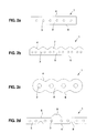
- FIGS. 2a to 2d different embodiments of support means 1 are shown, which can be used in a system for electrical contacting of tensile forces in suspension means.
- the support means 1 each have a jacket 5 and at least four tension members 3.
- the tension members 3 are arranged parallel to each other in the jacket 5, and lie substantially on one level.
- the number of tension members 3 and the shape of the shell 5 can be designed differently.
- FIG. 2a shows an exemplary support means 1 with a rectangular cross-section and six mutually parallel tension members 3.
- the support means 1 has a back 6 and a traction side 4.
- the support means 1 is designed symmetrically, ie the back 6 can be used as a traction side, or the traction side 4 can be used as a back.
- FIG. 2b is another exemplary suspension means 1 shown.
- the traction side 4 has longitudinal ribs 7.
- Such longitudinal ribs 7 improve the traction of the support means 1 and allow a precise lateral guidance of the support means 1 on drive or deflection rollers.
- the back 6 is as in FIG. 2a formed without additional structures.
- the support means 1 comprises six longitudinal ribs 7, wherein each longitudinal rib 7 are assigned two tension members 3. Thus, a total of twelve tension members 3 are arranged in the jacket 5 of the suspension element 1.
- FIG 2c is a further exemplary embodiment of a support means 1 is shown.
- the suspension element 1 comprises four tension members 3 in the jacket 5.
- the jacket 5 is contoured around the tension members 3, so that the traction side 4 and also the rear side 6 have a wave-like shape.
- FIG 2d is a further exemplary embodiment of a support means 1 is shown.
- This exemplary support means 1 comprises 8 mutually parallel tension members 3, which are surrounded by the jacket 5.
- the back 6 has a guide rib 8. This ensures that the support means 1, even if it is guided on its rear side 6 via deflection rollers, is laterally feasible.
- the support means 1 on its traction side 4 on two guide grooves 9. With appropriate guide grooves on a drive or deflection pulley, the suspension element 1 can thus be guided laterally.
- suspension means 1 are exemplary embodiments of a support means 1, which can be used in a system for electrical contacting of tension members in suspension means. It goes without saying that any other embodiments of suspension means can be used in such a system.
- FIGS. 3a to 3d are different embodiments of a contact element 10 for use in a system for electrical contacting of tension members shown in support means.
- These contact elements 10 each have a contact element body 12 and a cutting side 11.
- the cutting side 11 is adapted to penetrate the shell of a support means and thereby bring the contact element 10 to the tension members in the interior of the suspension element.
- the contact element body 12 is preferably made of an electrically conductive material, such as a metal.
- the contact element body 12 is also preferably sufficiently robust, so that the contact element 10 does not damage during insertion into the suspension element casing.
- the cutting side 11 is preferably constructed similar to a ridge of a knife edge to allow a corresponding cutting action.
- the cutting side 11 of the contact element 10 in FIG. 3b is essentially rectilinear.
- Such a contact element 10 can be used for many different support means, since the cutting side 11 is not tailored to a certain number and arrangement of the tension members in the support means.
- the cutting sides 11 in the FIGS. 3a, 3c and 3d an irregular shape.
- Such irregular shapes are matched to the support element to be used with the contact element 10.
- the contact element 10 is made FIG. 3a intended for a suspension with six tension members.
- the contact tips 13 enable reliable contacting of the individual tension members.
- the contact tips 13 facilitate a passage of the contact element 10 through the jacket of the suspension element.
- the contact recesses 14, or contact increases 15 in the Figures 3c and 3d serve a similar purpose as the contact tips 13 in FIG FIG. 3a ,
- the contact recesses 14 are arranged in a use state in each case by a tension member.
- the tension members are not contacted punctually, as is the case with contact tips, but the tension members are contacted on a larger part of their peripheral surface by the contact recesses 14 of the contact element 10.
- the contact increases 15 have a similar effect as the contact tips 13, with the difference that the contact increases 15 are rounded.
- the contact elements 10 in the FIGS. 3a to 3d are for use in a system for electrical contacting of tension members in suspension elements. It goes without saying that such a contact element 10 can be formed in various other ways, not shown.
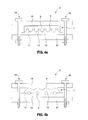
- FIGS. 4a and 4b In each case, a system for electrical contacting of tension members is shown in support means. It is in FIG. 4a a support means 1 with a rectangular cross section and six mutually parallel tension members 3 shown. In FIG. 4b is a support means 1 with a wave-shaped traction or back and four mutually parallel tension members 3 shown.
- the contact elements 10 used in the respective system are matched to the respective support means 1. So is in FIG. 4a contact element 10 is arranged with contact tips 13, wherein the number of contact tips 13 coincides with the number of tension members 3. In FIG. 4b Accordingly, a contact element 10 with contact recesses 14 is shown. Again, the number of contact recesses 14 with the number of tension members 3 is consistent.
- the support means 1 is in each case surrounded by a first and a second holding element 16, 17.
- the contact element 10 is supported in each case by the second holding element 17, so that the cutting side 11 of the contact element 10 is directed against the support means 1.
- the first and the second retaining element 16, 17 are connected to one another by a first fastening element 18 and a second fastening element 19.
- the fastening elements 18, 19 are mutually displaceable.
- the fastening elements 18, 19 are now operated until the contact element 10 contacts all tension members 3 of the suspension element 1.
- the fastening elements 18, 19 are each formed as a screw with nut. After contacting the tension members 3 by the contact element 10, a voltage is applied, so that a test current flows through the tension members 3 in order to determine the state of the tension members 3.
- only one fastener 18, 19 is provided, and the second fastener is replaced by a hinge.
- the two retaining elements 16, 17 are already connected to one another, which simplifies assembly, and only one fastening element 18, 19 has to be actuated in order to arrange the contacting device 2 on the suspension element 1.
Description
Gegenstand der Erfindung ist ein System zur elektrischen Kontaktierung von Zugträgern in Tragmitteln, um Tragmittel in Aufzugsanlagen zu überwachen.The invention relates to a system for electrical contacting of tension members in suspension means to monitor suspension means in elevator systems.
Bei manchen Fördereinrichtungen wie beispielsweise Aufzugsanlagen, Kranen oder Hebezügen, werden riemenförmige Tragmittel eingesetzt. Diese Tragmittel umfassen im Allgemeinen mehrere aus Strahldrähten bestehende Zugträger, welche die von dem Tragmittel aufzunehmenden Zugkräfte aufnehmen. Die Zugträger sind im Allgemeinen von einem Mantel aus Kunststoff umgeben. Der Mantel schützt die Zugträger beispielsweise vor mechanischem Verschleiss, weil die Tragmittel häufig über Umlenkstellen geführt werden. Zudem verbessert der Mantel die Traktion des Tragmittels auf Umlenk- oder Antriebsrollen, und fixiert die Anordnung der Zugträger untereinander.In some conveyors such as elevator systems, cranes or hoists, belt-shaped suspension means are used. These support means generally comprise a plurality of beam wires consisting of tensile carriers which absorb the tensile forces to be absorbed by the suspension element. The tension members are generally surrounded by a plastic sheath. The jacket protects the tension members, for example against mechanical wear, because the support means are often guided over deflection points. In addition, the jacket improves the traction of the suspension element on deflection or drive rollers, and fixed the arrangement of the tension members with each other.
Solche Tragmittel sind innerhalb einer Fördereinrichtung ein sicherheitskritisches Bauteil. Ihr Versagen, bzw. Bruch kann zu einem Herabfallen des zu fördernden Gutes führen. Dies kann zu erheblichen Sach- bzw. Personenschäden führen. Aus diesem Grund werden Prüfeinheiten in Fördereinrichtungen eingesetzt, welche insbesondere den mechanischen Zustand der Zugträger überprüfen. Schäden an den die Kräfte aufnehmenden Zugträgern sollen dadurch frühzeitig erkannt werden können, so dass das Tragmittel bei einer Beschädigung ausgewechselt werden kann, um ein Versagen der Fördereinrichtung zu verhindern.Such suspension means are within a conveyor a safety-critical component. Their failure, or breakage can lead to a fall of the good to be promoted. This can lead to considerable property damage or personal injury. For this reason, test units are used in conveyors, which in particular check the mechanical condition of the tension members. Damage to the forces absorbing tension members should be able to be detected early, so that the support means can be replaced in case of damage to prevent failure of the conveyor.
Die Zugträger sind von dem elektrisch isolierenden Mantel aus Kunststoff umgeben. Zur Durchführung einer Prüfung des Zustandes der Zugträger ist bei einigen Verfahren eine Kontaktierung eines Kontaktelementes mit dem Zugträger erforderlich. Bei einem bekannten Verfahren wird mit Hilfe des Kontaktelementes durch die Zugträger ein elektrischer Strom geleitet, der als Prüfstrom dazu dient, den Zustand der Zugträger festzustellen. Daneben kommen auch andere Prüfverfahren, die nicht mit elektrischem Strom arbeiten, z.B. Ultraschall, in Betracht.The tension members are surrounded by the electrically insulating jacket made of plastic. In order to carry out a test of the state of the tension members, contacting of a contact element with the tension member is required in some methods. In a known method, an electrical current is passed with the aid of the contact element through the tension members, which serves as a test current to determine the state of the tension members. In addition, other test methods that do not use electric current, e.g. Ultrasound, into consideration.
Die
Die
Eine Aufgabe der vorliegenden Erfindung besteht darin, ein System zur elektrischen Kontaktierung von Zugträgern in Tragmitteln zur Verfügung zu stellen, bei welchem die Zugträger des Tragmittels zuverlässig und in genauer Weise von einem Kontaktelement kontaktiert werden können, um einen Zustand der Zugträger ermitteln zu können. Das System soll in der Handhabung einfach und zuverlässig sein sowie geringe Herstellungskosten aufweisen.An object of the present invention is to provide a system for electrical contacting of tension members in support means available, in which the tension members of the support means can be reliably and accurately contacted by a contact element to determine a state of the tension members can. The system should be easy to use and reliable and have low production costs.
Zur Lösung dieser Aufgabe wird ein System zur elektrischen Kontaktierung von Zugträgern in Tragmitteln vorgeschlagen, welches ein Tragmittel und eine Kontaktierungsvorrichtung umfasst. Das Tragmittel hat einen Mantel und mindestens vier Zugträger, welche parallel zueinander im Mantel angeordnet sind, und welche im Wesentlichen auf einer Ebene liegen. Die Kontaktierungsvorrichtung hat ein Kontaktelement. Das Kontaktelement hat eine Schneidseite zur Durchdringung des Mantels, wobei die Schneidseite des Kontaktelements derart durch den Mantel geführt ist, dass das Kontaktelement die mindestens vier Zugträger zumindest mit der Schneidseite kontaktiert.To solve this problem, a system for electrical contacting of tension members in suspension means is proposed, which comprises a support means and a contacting device. The suspension element has a jacket and at least four tension members, which are arranged parallel to one another in the jacket, and which lie essentially on one plane. The contacting device has a contact element. The contact element has a cutting side for penetrating the jacket, wherein the cutting side of the contact element is guided through the jacket such that the contact element contacts the at least four tension members at least with the cutting side.
Diese Lösung hat den Vorteil, dass alle Zugträger eines Tragmittels mit nur einem Kontaktelement kontaktiert werden können. Somit muss nur ein Kontaktelement durch den Mantel des Tragmittels geführt werden. Dies vereinfacht die Anwendung dieses Systems zur elektrischen Kontaktierung von Zugträgern in Tragmitteln wesentlich. Zudem können durch ein solches System alle Zugträger im Tragmittel auf einfache Art und Weise parallel geschaltet werden.This solution has the advantage that all tension members of a suspension element can be contacted with only one contact element. Thus, only one contact element has to be guided through the jacket of the suspension element. This significantly simplifies the application of this system for the electrical contacting of tension members in suspension elements. In addition, by means of such a system, all tension members in the suspension element can be connected in parallel in a simple manner.
Das Kontaktelement mit der Schneidseite hat zudem den Vorteil, dass das Kontaktelement messerartig durch den Mantel getrieben werden kann, um die Zugträger zu kontaktieren.The contact element with the cutting side also has the advantage that the contact element can be driven like a knife through the jacket to contact the tension members.
Eine solche Schneidseite kann beispielsweise als geradlinige Kante ausgebildet sein, oder aber als gezackte Kante mit Kontaktspitzen oder als Kante mit Kontaktvertiefungen oder Kontakterhöhungen. Solche Kontaktspitzen oder Kontaktvertiefungen bzw. Kontakterhöhungen haben den Vorteil, dass die Zugträger jeweils von einer Kontaktspitze bzw. Kontaktvertiefung oder Kontakterhöhung zuverlässig kontaktiert werden können. Vorteilhafterweise ist jeweils eine Kontaktspitze bzw. Kontaktvertiefung bzw. Kontakterhöhung pro Zugträger vorgesehen. Dadurch können alle Zugträger eines Tragmittels mit einem einzigen Kontaktelement zuverlässig kontaktiert werden.Such a cutting side may be formed, for example, as a straight edge, or as a serrated edge with contact tips or as an edge with contact recesses or contact increases. Such contact tips or contact recesses or contact increases have the advantage that the tension members can each be reliably contacted by a contact tip or contact recess or contact increase. Advantageously, a contact tip or contact depression or contact increase per tensile carrier is provided in each case. As a result, all tensile carriers of a suspension element can be reliably contacted with a single contact element.
In einer weiteren vorteilhaften Ausführungsform umfasst die Kontaktierungsvorrichtung ein erstes und ein zweites Halteelement. Das Tragmittel ist dabei im Wesentlichen zwischen dem ersten und dem zweiten Halteelement angeordnet. Das Kontaktelement ist von einem der beiden Halteelemente gestützt, so dass die Schneidseite des Kontaktelementes gegen das Tragmittel gerichtet ist. Solche Halteelemente vereinfachen es, das Kontaktelement in gewünschter Weise durch den Mantel des Tragmittels zu führen.In a further advantageous embodiment, the contacting device comprises a first and a second holding element. The suspension element is arranged substantially between the first and the second holding element. The contact element is supported by one of the two holding elements, so that the cutting side of the contact element is directed against the support means. Such holding elements make it easier to guide the contact element in the desired manner by the jacket of the support means.
In einer weiteren vorteilhaften Ausführungsform sind das erste und zweite Halteelement durch ein erstes und ein zweites Befestigungselement miteinander verbunden. Vorteilhafterweise sind durch eine Betätigung des ersten und des zweiten Befestigungselementes das erste und zweite Halteelement zueinander verschiebbar. Dadurch können die Halteelemente zueinander geführt werden, um dadurch das Kontaktelement in den Mantel des Tragmittels zu treiben.In a further advantageous embodiment, the first and second retaining element are connected to each other by a first and a second fastening element. Advantageously, the actuation of the first and the second fastening element, the first and second retaining element to each other. As a result, the retaining elements can be guided relative to one another in order thereby to drive the contact element into the jacket of the suspension element.
In einer weiteren vorteilhaften Ausführungsform sind ein Scharnier und ein Befestigungselement vorgesehen, um das erste und das zweite Halteelement miteinander zu verbinden. Dies hat den Vorteil, dass nur ein Befestigungselement betätigt werden muss, um das erste und zweite Halteelement zueinander zu verschieben und dadurch das Kontaktelement in den Mantel des Tragmittels zu treiben.In a further advantageous embodiment, a hinge and a fastening element are provided in order to connect the first and the second retaining element to one another. This has the advantage that only one fastening element has to be actuated in order to displace the first and second retaining elements relative to one another and thereby to drive the contact element into the jacket of the suspension element.
In einer beispielhaften Ausführungsform sind das erste und das zweite Befestigungselement bzw. das eine Befestigungselement jeweils als Schraube mit Mutter ausgebildet. Es sind jedoch auch andere Ausführungsformen möglich.In an exemplary embodiment, the first and the second fastening element and the one fastening element are each designed as a screw with nut. However, other embodiments are possible.
In einer vorteilhaften Ausführungsform wird an einem ersten Kontaktelement, welches an einem ersten Tragmittelende angeordnet ist, in einem Verwendungszustand eine elektrische Spannung angelegt, wobei ein elektrischer Strom gemessen wird, welcher vom ersten Kontaktelement zu einem zweiten Kontaktelement, welches an einem zweiten Tragmittelende angeordnet ist, fliesst. Dadurch können allfällige Schäden in den Zugträgern festgestellt werden.In an advantageous embodiment, at a first contact element, which at a first end of the support means is arranged, applied in a use state, an electrical voltage, wherein an electric current is measured, which flows from the first contact element to a second contact element, which is arranged at a second Tragmittelende flows. As a result, any damage can be detected in the train carriers.
In einer weiteren vorteilhaften Ausführungsform weist das Tragmittel zumindest fünf Zugträger auf, wobei das Kontaktelement die zumindest fünf Zugträger kontaktiert.In a further advantageous embodiment, the suspension element has at least five tension members, wherein the contact element contacts the at least five tension members.
In einem weiteren vorteilhaften Ausführungsbeispiel wird eine Aufzugsanlage mit einem solchen System zur elektrischen Kontaktierung von Zugträgern in Tragmitteln zur Verfügung gestellt. Dabei sind die Kontaktierungsvorrichtungen vorzugsweise an nicht überrollten Bereichen des Tragmittels angeordnet.In a further advantageous embodiment, an elevator installation is provided with such a system for the electrical contacting of tension members in suspension elements. The contacting devices are preferably arranged on non-overrolled areas of the support means.
Einzelheiten und Vorteile der Erfindung werden im Folgenden anhand von Ausführungsbeispielen und mit Bezug auf die schematischen Zeichnungen beschrieben. Es zeigen:
- Fig. 1
- Eine beispielhafte Ausführungsform einer Aufzugsanlage mit einem System zur elektrischen Kontaktierung von Zugträgern in Tragmitteln;
- Fig. 2a bis 2d
- Beispielhafte Ausführungsformen von Tragmitteln zur Verwendung in einem System zur elektrischen Kontaktierung von Zugträgern in Tragmitteln;
- Fig. 3a bis 3d
- Beispielhafte Ausführungsformen eines Kontaktelementes zur Verwendung in einem System zur elektrischen Kontaktierung von Zugträgern in Tragmitteln; und
- Fig. 4a und 4b
- Beispielhafte Ausführungsformen eines Systems zur elektrischen Kontaktierung von Zugträgern in Tragmitteln mit einem Tragmittel und einer Kontaktierungsvorrichtung.
- Fig. 1
- An exemplary embodiment of an elevator installation with a system for the electrical contacting of tension members in suspension elements;
- Fig. 2a to 2d
- Exemplary embodiments of suspension elements for use in a system for electrical contacting of tension members in suspension elements;
- Fig. 3a to 3d
- Exemplary embodiments of a contact element for use in a system for the electrical contacting of tension members in suspension elements; and
- Fig. 4a and 4b
- Exemplary embodiments of a system for electrical contacting of tension members in suspension elements with a suspension element and a contacting device.
In
Ein loses Ende 1.1 des Tragmittels 1 ist mit der Kontaktierungsvorrichtung 2 zur temporären oder permanenten Kontaktierung des Tragmittels 1 versehen. Im dargestellten Beispiel ist an beiden Enden des Tragmittels 1 eine derartige Kontaktierungsvorrichtung 2 angeordnet. In einer alternativen nicht dargestellten Ausführungsform ist nur eine Kontaktierungsvorrichtung 2 an einem der Tragmittelenden 1.1 angeordnet. Die Tragmittelenden 1.1 sind von der Zugkraft im Tragmittel 1 nicht mehr belastet, da diese Zugkraft bereits vorgängig über die Tragmittelbefestigungen 47 in das Gebäude geleitet ist. Die Kontaktierungsvorrichtungen 2 sind also in einem nicht überrollten Bereich des Tragmittels 1 angeordnet.A loose end 1.1 of the
Die gezeigte Aufzugsanlage 40 in
In den
In
In
In
Die in den
In den
Die Schneidseite 11 des Kontaktelementes 10 in
Die Kontaktelemente 10 in den
In den
Das Tragmittel 1 ist jeweils von einem ersten und einem zweiten Halteelement 16, 17 umgeben. Dabei ist das Kontaktelement 10 jeweils vom zweiten Halteelement 17 gestützt, so dass die Schneidseite 11 des Kontaktelementes 10 gegen das Tragmittel 1 gerichtet ist. Das erste und das zweite Halteelement 16, 17 sind durch ein erstes Befestigungselement 18 und ein zweites Befestigungselement 19 miteinander verbunden. Durch eine Betätigung der Befestigungselemente 18, 19 sind das erste und das zweite Halteelement 16, 17 zueinander verschiebbar. Durch eine solche Betätigung der Befestigungselemente 18, 19 wird also das Kontaktelement 10 in den Mantel 5 des Tragmittels 1 geführt. Die Befestigungselemente 18, 19 werden nun solange betätigt, bis das Kontaktelement 10 alle Zugträger 3 des Tragmittels 1 kontaktiert. In diesem Ausführungsbeispiel sind die Befestigungselemente 18, 19 jeweils als Schraube mit Mutter ausgebildet. Nach erfolgter Kontaktierung der Zugträger 3 durch das Kontaktelement 10 wird eine Spannung angelegt, so dass ein Prüfstrom durch die Zugträger 3 fliesst, um den Zustand der Zugträger 3 zu ermitteln.The support means 1 is in each case surrounded by a first and a
In einer alternativen nicht dargestellten Ausführungsform ist nur ein Befestigungselement 18, 19 vorgesehen, und das zweite Befestigungselement ist durch ein Scharnier ersetzt. Dadurch sind die beiden Halteelement 16, 17 bereits miteinander verbunden, was eine Montage vereinfacht, und es muss nur ein Befestigungselement 18, 19 betätigt werden, um die Kontaktierungsvorrichtung 2 am Tragmittel 1 anzuordnen.In an alternative embodiment, not shown, only one
Claims (13)
- System for electrical contacting of tensile carriers (3) in support means (1), the system comprising:a support means (1) with a casing (5) and at least four tensile carriers (3), which are arranged parallel to one another in the casing (5) and which lie substantially in one plane, anda contacting device (2) with a contact element (10),characterised in that the contact element (10) has a cutting side (11) for penetrating the casing (5),wherein the cutting side (11) of the contact element (10) is so guided through the casing (5) that the contact element (10) contacts the at least four tensile carriers (3) at least by the cutting side (11).
- System according to claim 1, wherein the cutting side (11) is constructed as a substantially rectilinear edge.
- System according to claim 1, wherein the cutting side (11) is constructed as a serrated edge with at least four contact points (13) and wherein each tensile carrier (3) of the at least four tensile carriers (3) is contacted by a respective contact point (13).
- System according to claim 1, wherein the cutting side (11) has at least four contact depressions (14) and wherein each tensile carrier (3) of the at least four tensile carriers (3) is contacted by a respective contact depression (14).
- System according to claim 1, wherein the cutting side (11) has at least four contact elevations (15) and wherein each tensile carrier (3) of the at least four tensile carriers (3) is contacted by a respective contact elevation (15).
- System according to any one of the preceding claims, wherein the contacting device (2) further comprises a first holding element (16) and a second holding element (17) and wherein the support means (3) is arranged substantially between the first and second holding elements (16, 17).
- System according to claim 6, wherein the contact element (10) is supported at the second holding element (17) so that the cutting side (11) is directed towards the support means (1).
- System according to one of claims 6 and 7, wherein the first and second holding elements (16, 17) are connected together by at least one fastening element (18, 19).
- System according to claim 8, wherein the first and second holding elements (16, 17) are displaceable relative to one another by actuation of the at least one fastening element (18, 19).
- System according to claim 9, wherein the at least one fastening element (18, 19) is constructed as a screw with a nut.
- System according to any one of the preceding claims, wherein in a use state an electrical voltage is applied to the contact element (10) in order to detect damage of the tensile carriers (3).
- System according to any one of the preceding claims, wherein the support means (1) comprises at least five tensile carriers (3) and wherein the contact element (10) contacts the at least five tensile carriers (3).
- Lift installation (40) with a system according to any one of the preceding claims.
Priority Applications (1)
| Application Number | Priority Date | Filing Date | Title |
|---|---|---|---|
| EP12794952.7A EP2791040B1 (en) | 2011-12-16 | 2012-11-29 | System for making electrical contact with tension members in load-bearing means |
Applications Claiming Priority (3)
| Application Number | Priority Date | Filing Date | Title |
|---|---|---|---|
| EP11193958 | 2011-12-16 | ||
| PCT/EP2012/073987 WO2013087418A1 (en) | 2011-12-16 | 2012-11-29 | System for making electrical contact with tension members in load-bearing means |
| EP12794952.7A EP2791040B1 (en) | 2011-12-16 | 2012-11-29 | System for making electrical contact with tension members in load-bearing means |
Publications (2)
| Publication Number | Publication Date |
|---|---|
| EP2791040A1 EP2791040A1 (en) | 2014-10-22 |
| EP2791040B1 true EP2791040B1 (en) | 2015-04-15 |
Family
ID=47278824
Family Applications (1)
| Application Number | Title | Priority Date | Filing Date |
|---|---|---|---|
| EP12794952.7A Active EP2791040B1 (en) | 2011-12-16 | 2012-11-29 | System for making electrical contact with tension members in load-bearing means |
Country Status (7)
| Country | Link |
|---|---|
| US (1) | US9385447B2 (en) |
| EP (1) | EP2791040B1 (en) |
| CN (1) | CN103974892B (en) |
| AU (1) | AU2012350955B2 (en) |
| CA (1) | CA2855888C (en) |
| CO (1) | CO7051018A2 (en) |
| WO (1) | WO2013087418A1 (en) |
Families Citing this family (8)
| Publication number | Priority date | Publication date | Assignee | Title |
|---|---|---|---|---|
| BR112012000284A2 (en) * | 2009-07-06 | 2016-02-23 | Inventio Ag | contact device |
| WO2014064022A1 (en) | 2012-10-22 | 2014-05-01 | Inventio Ag | Monitoring of supporting means in elevator systems |
| EP2909124B1 (en) * | 2012-10-22 | 2016-12-14 | Inventio AG | Load-bearing medium for a lift system |
| US10730720B2 (en) | 2014-10-22 | 2020-08-04 | Inventio Ag | Method for monitoring elevator system suspension apparatus |
| CA2966952C (en) * | 2014-11-28 | 2023-05-23 | Inventio Ag | Suspension means monitoring in an elevator system |
| EP3028979A1 (en) * | 2014-12-01 | 2016-06-08 | KONE Corporation | Method for manufacturing an electrical contact arrangement and arrangement |
| EP3053867A1 (en) * | 2015-02-03 | 2016-08-10 | KONE Corporation | Rope terminal arrangement, arrangement for condition monitoring of an elevator rope and elevator |
| US11299370B2 (en) * | 2018-06-29 | 2022-04-12 | Otis Elevator Company | Data transmission via elevator system tension member |
Family Cites Families (12)
| Publication number | Priority date | Publication date | Assignee | Title |
|---|---|---|---|---|
| CH559433A5 (en) * | 1972-11-28 | 1975-02-28 | Sprecher & Schuh Ag | |
| DE3934654A1 (en) | 1989-10-14 | 1991-05-23 | Sondermaschinenbau Peter Suhli | Break testing of continuous carrier belt - using carrier strands in non-conducting strap interconnected to form continuous conducting body |
| EP1530040B1 (en) * | 2003-11-04 | 2012-09-12 | Inventio AG | Method and device for checking carrying means |
| EP1730065B1 (en) * | 2004-03-16 | 2011-04-27 | Otis Elevator Company | Electrical connector and restraining device for use with elevator belts |
| ES2356739T3 (en) * | 2004-03-16 | 2011-04-12 | Otis Elevator Company | AN ELECTRICAL CONNECTOR DEVICE FOR USE WITH ELEVATOR LOAD SUPPORT MEMBERS. |
| WO2005094249A2 (en) | 2004-03-16 | 2005-10-13 | Otis Elevator Company | Electrical connector device for use with elevator load bearing members |
| JP2006182566A (en) * | 2004-12-24 | 2006-07-13 | Inventio Ag | Device with belt-shaped driving means and method for transmitting electric energy or signal therein |
| WO2006127059A2 (en) * | 2005-05-20 | 2006-11-30 | Otis Elevator Company | Electrical connector for piercing a conductive member |
| JP4916982B2 (en) * | 2007-09-19 | 2012-04-18 | スタンレー電気株式会社 | Connector for multi-core flat cable |
| MY154186A (en) * | 2008-11-19 | 2015-05-15 | Inventio Ag | Supporting belt |
| EP2451735B1 (en) * | 2009-07-06 | 2014-02-26 | Inventio AG | Contacting device |
| JP5514328B2 (en) * | 2010-02-10 | 2014-06-04 | オーチス エレベータ カンパニー | Elevator system belt with connecting device |
-
2012
- 2012-11-29 CA CA2855888A patent/CA2855888C/en active Active
- 2012-11-29 EP EP12794952.7A patent/EP2791040B1/en active Active
- 2012-11-29 AU AU2012350955A patent/AU2012350955B2/en active Active
- 2012-11-29 WO PCT/EP2012/073987 patent/WO2013087418A1/en active Application Filing
- 2012-11-29 CN CN201280060669.9A patent/CN103974892B/en active Active
- 2012-12-14 US US13/714,507 patent/US9385447B2/en active Active
-
2014
- 2014-06-13 CO CO14128711A patent/CO7051018A2/en unknown
Also Published As
| Publication number | Publication date |
|---|---|
| CN103974892A (en) | 2014-08-06 |
| EP2791040A1 (en) | 2014-10-22 |
| CO7051018A2 (en) | 2014-09-10 |
| WO2013087418A1 (en) | 2013-06-20 |
| CA2855888A1 (en) | 2013-06-20 |
| US20130157497A1 (en) | 2013-06-20 |
| AU2012350955A1 (en) | 2014-07-10 |
| AU2012350955B2 (en) | 2017-08-10 |
| CA2855888C (en) | 2020-09-29 |
| CN103974892B (en) | 2016-10-12 |
| US9385447B2 (en) | 2016-07-05 |
Similar Documents
| Publication | Publication Date | Title |
|---|---|---|
| EP2791040B1 (en) | System for making electrical contact with tension members in load-bearing means | |
| EP2346768B1 (en) | Supporting belt | |
| EP2451734B1 (en) | Contacting device | |
| EP2909123B1 (en) | Monitoring of load-bearing devices in lift systems | |
| EP2925656B1 (en) | Lift assembly | |
| EP2935071B1 (en) | Lift assembly with monitoring device and method for monitoring a lift assembly | |
| EP3083479B1 (en) | Method for installing a lift system and a device | |
| DE2330038A1 (en) | CONTACT PIECE FOR ELECTRICAL CONNECTION OF A FLAT CABLE | |
| EP2794448A1 (en) | Elevator system | |
| WO2016046052A1 (en) | Elevator system | |
| EP2679522A1 (en) | Transport belt element for conveying goods, method for guiding a transport belt element and an assembly consisting of a transport belt element and a guiding and/or drive roller device | |
| EP2451735B1 (en) | Contacting device | |
| WO2016062454A1 (en) | Elevator system | |
| EP3555369B1 (en) | Method for installing a tensioning element in an anchor block, holder, in particular for carrying out the method and combination of a holder with a prestressing element | |
| EP3224181B1 (en) | Elevator system | |
| EP3433198B1 (en) | Lift system with load-bearing means partially surrounded by an electrically conductive housing, in particular at a deflection roller assembly | |
| DE19958734B4 (en) | Fall protection system and trolley for use in such a system | |
| EP3288886B1 (en) | Lift system | |
| EP3681834A1 (en) | Method for electrical attachment of a connecting element to a belt for a lift system and corresponding belt assembly | |
| DE102019201783A1 (en) | Elevator system with car earthing | |
| EP2230732B1 (en) | Device for attaching a cable to a connection element | |
| EP2535157A1 (en) | Belt or chain drive | |
| EP3042874A1 (en) | Lift belt monitoring | |
| DE102010023783A1 (en) | Heating device i.e. heater, for heating user-affected surface in passenger compartment of passenger car, has carrier provided for carrying conductor or conductor lead, and unloading device decreasing mechanical load of conductor or lead | |
| WO2014191374A1 (en) | Elevator system |
Legal Events
| Date | Code | Title | Description |
|---|---|---|---|
| PUAI | Public reference made under article 153(3) epc to a published international application that has entered the european phase |
Free format text: ORIGINAL CODE: 0009012 |
|
| 17P | Request for examination filed |
Effective date: 20140513 |
|
| AK | Designated contracting states |
Kind code of ref document: A1 Designated state(s): AL AT BE BG CH CY CZ DE DK EE ES FI FR GB GR HR HU IE IS IT LI LT LU LV MC MK MT NL NO PL PT RO RS SE SI SK SM TR |
|
| GRAP | Despatch of communication of intention to grant a patent |
Free format text: ORIGINAL CODE: EPIDOSNIGR1 |
|
| DAX | Request for extension of the european patent (deleted) | ||
| INTG | Intention to grant announced |
Effective date: 20141127 |
|
| GRAS | Grant fee paid |
Free format text: ORIGINAL CODE: EPIDOSNIGR3 |
|
| GRAA | (expected) grant |
Free format text: ORIGINAL CODE: 0009210 |
|
| AK | Designated contracting states |
Kind code of ref document: B1 Designated state(s): AL AT BE BG CH CY CZ DE DK EE ES FI FR GB GR HR HU IE IS IT LI LT LU LV MC MK MT NL NO PL PT RO RS SE SI SK SM TR |
|
| REG | Reference to a national code |
Ref country code: GB Ref legal event code: FG4D Free format text: NOT ENGLISH Ref country code: CH Ref legal event code: EP |
|
| REG | Reference to a national code |
Ref country code: IE Ref legal event code: FG4D Free format text: LANGUAGE OF EP DOCUMENT: GERMAN |
|
| REG | Reference to a national code |
Ref country code: AT Ref legal event code: REF Ref document number: 721833 Country of ref document: AT Kind code of ref document: T Effective date: 20150515 |
|
| REG | Reference to a national code |
Ref country code: DE Ref legal event code: R096 Ref document number: 502012002883 Country of ref document: DE Effective date: 20150528 |
|
| REG | Reference to a national code |
Ref country code: NL Ref legal event code: VDEP Effective date: 20150415 |
|
| REG | Reference to a national code |
Ref country code: LT Ref legal event code: MG4D |
|
| PG25 | Lapsed in a contracting state [announced via postgrant information from national office to epo] |
Ref country code: NL Free format text: LAPSE BECAUSE OF FAILURE TO SUBMIT A TRANSLATION OF THE DESCRIPTION OR TO PAY THE FEE WITHIN THE PRESCRIBED TIME-LIMIT Effective date: 20150415 |
|
| PG25 | Lapsed in a contracting state [announced via postgrant information from national office to epo] |
Ref country code: HR Free format text: LAPSE BECAUSE OF FAILURE TO SUBMIT A TRANSLATION OF THE DESCRIPTION OR TO PAY THE FEE WITHIN THE PRESCRIBED TIME-LIMIT Effective date: 20150415 Ref country code: ES Free format text: LAPSE BECAUSE OF FAILURE TO SUBMIT A TRANSLATION OF THE DESCRIPTION OR TO PAY THE FEE WITHIN THE PRESCRIBED TIME-LIMIT Effective date: 20150415 Ref country code: NO Free format text: LAPSE BECAUSE OF FAILURE TO SUBMIT A TRANSLATION OF THE DESCRIPTION OR TO PAY THE FEE WITHIN THE PRESCRIBED TIME-LIMIT Effective date: 20150715 Ref country code: FI Free format text: LAPSE BECAUSE OF FAILURE TO SUBMIT A TRANSLATION OF THE DESCRIPTION OR TO PAY THE FEE WITHIN THE PRESCRIBED TIME-LIMIT Effective date: 20150415 Ref country code: PT Free format text: LAPSE BECAUSE OF FAILURE TO SUBMIT A TRANSLATION OF THE DESCRIPTION OR TO PAY THE FEE WITHIN THE PRESCRIBED TIME-LIMIT Effective date: 20150817 Ref country code: LT Free format text: LAPSE BECAUSE OF FAILURE TO SUBMIT A TRANSLATION OF THE DESCRIPTION OR TO PAY THE FEE WITHIN THE PRESCRIBED TIME-LIMIT Effective date: 20150415 |
|
| REG | Reference to a national code |
Ref country code: FR Ref legal event code: PLFP Year of fee payment: 4 |
|
| PG25 | Lapsed in a contracting state [announced via postgrant information from national office to epo] |
Ref country code: IS Free format text: LAPSE BECAUSE OF FAILURE TO SUBMIT A TRANSLATION OF THE DESCRIPTION OR TO PAY THE FEE WITHIN THE PRESCRIBED TIME-LIMIT Effective date: 20150815 Ref country code: RS Free format text: LAPSE BECAUSE OF FAILURE TO SUBMIT A TRANSLATION OF THE DESCRIPTION OR TO PAY THE FEE WITHIN THE PRESCRIBED TIME-LIMIT Effective date: 20150415 Ref country code: LV Free format text: LAPSE BECAUSE OF FAILURE TO SUBMIT A TRANSLATION OF THE DESCRIPTION OR TO PAY THE FEE WITHIN THE PRESCRIBED TIME-LIMIT Effective date: 20150415 Ref country code: GR Free format text: LAPSE BECAUSE OF FAILURE TO SUBMIT A TRANSLATION OF THE DESCRIPTION OR TO PAY THE FEE WITHIN THE PRESCRIBED TIME-LIMIT Effective date: 20150716 |
|
| REG | Reference to a national code |
Ref country code: DE Ref legal event code: R097 Ref document number: 502012002883 Country of ref document: DE |
|
| PG25 | Lapsed in a contracting state [announced via postgrant information from national office to epo] |
Ref country code: EE Free format text: LAPSE BECAUSE OF FAILURE TO SUBMIT A TRANSLATION OF THE DESCRIPTION OR TO PAY THE FEE WITHIN THE PRESCRIBED TIME-LIMIT Effective date: 20150415 Ref country code: DK Free format text: LAPSE BECAUSE OF FAILURE TO SUBMIT A TRANSLATION OF THE DESCRIPTION OR TO PAY THE FEE WITHIN THE PRESCRIBED TIME-LIMIT Effective date: 20150415 |
|
| PLBE | No opposition filed within time limit |
Free format text: ORIGINAL CODE: 0009261 |
|
| STAA | Information on the status of an ep patent application or granted ep patent |
Free format text: STATUS: NO OPPOSITION FILED WITHIN TIME LIMIT |
|
| PG25 | Lapsed in a contracting state [announced via postgrant information from national office to epo] |
Ref country code: CZ Free format text: LAPSE BECAUSE OF FAILURE TO SUBMIT A TRANSLATION OF THE DESCRIPTION OR TO PAY THE FEE WITHIN THE PRESCRIBED TIME-LIMIT Effective date: 20150415 Ref country code: RO Free format text: LAPSE BECAUSE OF NON-PAYMENT OF DUE FEES Effective date: 20150415 Ref country code: PL Free format text: LAPSE BECAUSE OF FAILURE TO SUBMIT A TRANSLATION OF THE DESCRIPTION OR TO PAY THE FEE WITHIN THE PRESCRIBED TIME-LIMIT Effective date: 20150415 Ref country code: SK Free format text: LAPSE BECAUSE OF FAILURE TO SUBMIT A TRANSLATION OF THE DESCRIPTION OR TO PAY THE FEE WITHIN THE PRESCRIBED TIME-LIMIT Effective date: 20150415 |
|
| 26N | No opposition filed |
Effective date: 20160118 |
|
| PG25 | Lapsed in a contracting state [announced via postgrant information from national office to epo] |
Ref country code: SI Free format text: LAPSE BECAUSE OF FAILURE TO SUBMIT A TRANSLATION OF THE DESCRIPTION OR TO PAY THE FEE WITHIN THE PRESCRIBED TIME-LIMIT Effective date: 20150415 |
|
| PG25 | Lapsed in a contracting state [announced via postgrant information from national office to epo] |
Ref country code: MC Free format text: LAPSE BECAUSE OF FAILURE TO SUBMIT A TRANSLATION OF THE DESCRIPTION OR TO PAY THE FEE WITHIN THE PRESCRIBED TIME-LIMIT Effective date: 20150415 Ref country code: LU Free format text: LAPSE BECAUSE OF FAILURE TO SUBMIT A TRANSLATION OF THE DESCRIPTION OR TO PAY THE FEE WITHIN THE PRESCRIBED TIME-LIMIT Effective date: 20151129 |
|
| REG | Reference to a national code |
Ref country code: CH Ref legal event code: PL |
|
| PG25 | Lapsed in a contracting state [announced via postgrant information from national office to epo] |
Ref country code: LI Free format text: LAPSE BECAUSE OF NON-PAYMENT OF DUE FEES Effective date: 20151130 Ref country code: CH Free format text: LAPSE BECAUSE OF NON-PAYMENT OF DUE FEES Effective date: 20151130 |
|
| REG | Reference to a national code |
Ref country code: IE Ref legal event code: MM4A |
|
| PG25 | Lapsed in a contracting state [announced via postgrant information from national office to epo] |
Ref country code: IE Free format text: LAPSE BECAUSE OF NON-PAYMENT OF DUE FEES Effective date: 20151129 |
|
| REG | Reference to a national code |
Ref country code: FR Ref legal event code: PLFP Year of fee payment: 5 |
|
| PG25 | Lapsed in a contracting state [announced via postgrant information from national office to epo] |
Ref country code: BG Free format text: LAPSE BECAUSE OF FAILURE TO SUBMIT A TRANSLATION OF THE DESCRIPTION OR TO PAY THE FEE WITHIN THE PRESCRIBED TIME-LIMIT Effective date: 20150415 Ref country code: SM Free format text: LAPSE BECAUSE OF FAILURE TO SUBMIT A TRANSLATION OF THE DESCRIPTION OR TO PAY THE FEE WITHIN THE PRESCRIBED TIME-LIMIT Effective date: 20150415 |
|
| PG25 | Lapsed in a contracting state [announced via postgrant information from national office to epo] |
Ref country code: CY Free format text: LAPSE BECAUSE OF FAILURE TO SUBMIT A TRANSLATION OF THE DESCRIPTION OR TO PAY THE FEE WITHIN THE PRESCRIBED TIME-LIMIT Effective date: 20150415 Ref country code: SE Free format text: LAPSE BECAUSE OF FAILURE TO SUBMIT A TRANSLATION OF THE DESCRIPTION OR TO PAY THE FEE WITHIN THE PRESCRIBED TIME-LIMIT Effective date: 20150415 Ref country code: HU Free format text: LAPSE BECAUSE OF FAILURE TO SUBMIT A TRANSLATION OF THE DESCRIPTION OR TO PAY THE FEE WITHIN THE PRESCRIBED TIME-LIMIT; INVALID AB INITIO Effective date: 20121129 |
|
| GBPC | Gb: european patent ceased through non-payment of renewal fee |
Effective date: 20161129 |
|
| PG25 | Lapsed in a contracting state [announced via postgrant information from national office to epo] |
Ref country code: BE Free format text: LAPSE BECAUSE OF NON-PAYMENT OF DUE FEES Effective date: 20151130 |
|
| PG25 | Lapsed in a contracting state [announced via postgrant information from national office to epo] |
Ref country code: MT Free format text: LAPSE BECAUSE OF FAILURE TO SUBMIT A TRANSLATION OF THE DESCRIPTION OR TO PAY THE FEE WITHIN THE PRESCRIBED TIME-LIMIT Effective date: 20150415 |
|
| REG | Reference to a national code |
Ref country code: FR Ref legal event code: PLFP Year of fee payment: 6 |
|
| PG25 | Lapsed in a contracting state [announced via postgrant information from national office to epo] |
Ref country code: GB Free format text: LAPSE BECAUSE OF NON-PAYMENT OF DUE FEES Effective date: 20161129 |
|
| PG25 | Lapsed in a contracting state [announced via postgrant information from national office to epo] |
Ref country code: MK Free format text: LAPSE BECAUSE OF FAILURE TO SUBMIT A TRANSLATION OF THE DESCRIPTION OR TO PAY THE FEE WITHIN THE PRESCRIBED TIME-LIMIT Effective date: 20150415 |
|
| PG25 | Lapsed in a contracting state [announced via postgrant information from national office to epo] |
Ref country code: TR Free format text: LAPSE BECAUSE OF FAILURE TO SUBMIT A TRANSLATION OF THE DESCRIPTION OR TO PAY THE FEE WITHIN THE PRESCRIBED TIME-LIMIT Effective date: 20150415 Ref country code: AL Free format text: LAPSE BECAUSE OF FAILURE TO SUBMIT A TRANSLATION OF THE DESCRIPTION OR TO PAY THE FEE WITHIN THE PRESCRIBED TIME-LIMIT Effective date: 20150415 |
|
| REG | Reference to a national code |
Ref country code: AT Ref legal event code: MM01 Ref document number: 721833 Country of ref document: AT Kind code of ref document: T Effective date: 20171129 |
|
| PG25 | Lapsed in a contracting state [announced via postgrant information from national office to epo] |
Ref country code: AT Free format text: LAPSE BECAUSE OF NON-PAYMENT OF DUE FEES Effective date: 20171129 |
|
| PGFP | Annual fee paid to national office [announced via postgrant information from national office to epo] |
Ref country code: IT Payment date: 20231124 Year of fee payment: 12 Ref country code: FR Payment date: 20231123 Year of fee payment: 12 Ref country code: DE Payment date: 20231127 Year of fee payment: 12 |