EP2790484B1 - Link holder - Google Patents
Link holder Download PDFInfo
- Publication number
- EP2790484B1 EP2790484B1 EP12775010.7A EP12775010A EP2790484B1 EP 2790484 B1 EP2790484 B1 EP 2790484B1 EP 12775010 A EP12775010 A EP 12775010A EP 2790484 B1 EP2790484 B1 EP 2790484B1
- Authority
- EP
- European Patent Office
- Prior art keywords
- link
- holder
- rail
- vehicle
- machine
- Prior art date
- Legal status (The legal status is an assumption and is not a legal conclusion. Google has not performed a legal analysis and makes no representation as to the accuracy of the status listed.)
- Not-in-force
Links
Images

Classifications
-
- A—HUMAN NECESSITIES
- A01—AGRICULTURE; FORESTRY; ANIMAL HUSBANDRY; HUNTING; TRAPPING; FISHING
- A01B—SOIL WORKING IN AGRICULTURE OR FORESTRY; PARTS, DETAILS, OR ACCESSORIES OF AGRICULTURAL MACHINES OR IMPLEMENTS, IN GENERAL
- A01B59/00—Devices specially adapted for connection between animals or tractors and agricultural machines or implements
- A01B59/06—Devices specially adapted for connection between animals or tractors and agricultural machines or implements for machines mounted on tractors
- A01B59/066—Devices specially adapted for connection between animals or tractors and agricultural machines or implements for machines mounted on tractors of the type comprising at least two lower arms and one upper arm generally arranged in a triangle, e.g. three-point hitches
-
- A—HUMAN NECESSITIES
- A01—AGRICULTURE; FORESTRY; ANIMAL HUSBANDRY; HUNTING; TRAPPING; FISHING
- A01B—SOIL WORKING IN AGRICULTURE OR FORESTRY; PARTS, DETAILS, OR ACCESSORIES OF AGRICULTURAL MACHINES OR IMPLEMENTS, IN GENERAL
- A01B59/00—Devices specially adapted for connection between animals or tractors and agricultural machines or implements
- A01B59/04—Devices specially adapted for connection between animals or tractors and agricultural machines or implements for machines pulled or pushed by a tractor
- A01B59/042—Devices specially adapted for connection between animals or tractors and agricultural machines or implements for machines pulled or pushed by a tractor having pulling means arranged on the rear part of the tractor
- A01B59/043—Devices specially adapted for connection between animals or tractors and agricultural machines or implements for machines pulled or pushed by a tractor having pulling means arranged on the rear part of the tractor supported at three points, e.g. by quick-release couplings
-
- A—HUMAN NECESSITIES
- A01—AGRICULTURE; FORESTRY; ANIMAL HUSBANDRY; HUNTING; TRAPPING; FISHING
- A01B—SOIL WORKING IN AGRICULTURE OR FORESTRY; PARTS, DETAILS, OR ACCESSORIES OF AGRICULTURAL MACHINES OR IMPLEMENTS, IN GENERAL
- A01B59/00—Devices specially adapted for connection between animals or tractors and agricultural machines or implements
- A01B59/002—Details, component parts
Definitions
- This invention relates to a link holder on a vehicle or machine. More specifically, this invention relates to a top link holder on a vehicle or machine.
- Vehicles or machines such as agricultural tractors are provided with hitch devices to enable an implement to be attached to them.
- a top link holder which can facilitate the handling of a top link of a three-point-hitch device on the rear of a tractor.
- the top link is pivotally attached to the tractor to allow movement about a horizontal axis. Movement about a vertical axis may also be possible. If the top link is not in use a top link holder holds the top link in a parking position which is a substantially vertical position so that it cannot move about the vertical or horizontal axis. If the operator has to couple the top link to an implement, the top link is released from the holder and the top link is pulled downwards to a coupling point of the implement. The top link is heavy and if the operator drops the top link during coupling the link can cause damage to the operator or a part of the tractor, or be damaged itself.
- top link holders comprise a crude metal rod fixed to a part of the tractor and which extends in a substantially vertical direction.
- the rod is provided with a simple securing mechanism to secure the top link to the rod in the parking position.
- the securing mechanism may be a hook for example.
- To release the top link the securing mechanism is released and the operator pulls and supports the top link to lower it safely.
- Other known top link holders comprise a metal rod which is movably fixed to the tractor and is provided with a ball element and the hook of the top link can be attached to hold the top link in the parking position.
- EP1982854 discloses another example of a link holder.
- a link holder for controlling movement of an extendible pivotable link on a vehicle or machine, said holder comprising a first elongated element and a second elongated element which are moveably connected together at each end, wherein a free end of the first elongated element is attachable to the vehicle or machine and a free end of the second element is pivotally attachable to the link, said holder further comprising a connecting element which connects an extendible part of the link to the second element, wherein the link is pivotally raised by extending the link and pivotally lowered by retracting the link.
- the link is automatically pivoted to a parking position upon extension of the extendible part of the link.
- parking position it is meant a link storage position for when the top link is not in use in which the link is secured in a substantially vertical position.
- the link holder is attached to a rail on the vehicle or machine.
- the rail is preferably formed so that the first element can pivot about a fixed point in the rail and (if necessary) can move linearly along the rail.
- the link holder may be provided with serrated edges to engage with a protrusion on the first element. This way the link can be held at a desired position and if the operator removes the connecting element from the extendible part of the link, the link will not drop to the ground but be held within the serrations.
- the connecting element is preferably a link indication rod associated with the link. More preferably, the link is moved into a parking position by extending the link.
- the link is preferably a top link. More preferably, the vehicle is an agricultural tractor.
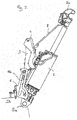
- a link holder 1 which is attached to a link 2.
- the link 2 is an extendible link on a machine or vehicle, such as a top link which is mounted on the rear of an agricultural tractor 1a.
- the link is provided with a hook 2a which can be extended or retracted.
- the link 2 is pivotably attached to the vehicle, or machine at pivot point 5b.
- the tractor 1a is provided with two other pivot points 5a and 5c to attach the top link to the tractor at different heights.
- the holder 1 comprises a first elongated element 3 and a second elongated element 4 which are moveably connected together at each end.
- the free end of the second element 4 is pivotably attached to the link 2 and the free end of the first element 3 is moveably connected to the tractor by way of a rail 6.
- the first element 3 is provided with two guiding elements 7a, 7b which slide within the rail 6.
- Rail 6 comprises two parallel plates having cut out portions. Each of the plates has a linear portion 6a and a curved portion 6b which allows both linear movement and pivotal movement of the first element 3.
- the outer edges of curved portions 6b are serrated 10, so that a notch, or notches 11 located on the first element 3 can engage with the serrations to as a safety feature to prevent the link falling.
- the link 2 is provided with a link indication rod 8 (as is common with extendible links) which shows the operator at a glance how much the link 2 is extended.
- link 2 may be partly extended so that the link indication rod 8 can be attached to the second element 4 as shown in figure 1 . If the link is attached to a different pivot point it is possible to connect the extendible part of the top link to the second element when in a fully retracted position.
- the position of link 2 in figure 1 is somewhere between the parking position in which the link is in a substantially vertical position and a coupling position in which the link is in a substantially horizontal position for attachment to a trailer, or implement.
- first element 3 moves upward in the curved portion 6b of the rail 6 and lifts the link indication rod 8 and thus the link 2. Since link 2 is pivotably attached to the tractor, first element 3 initially pivots about guiding element 7a in rail 6 as guiding element 7b moves along the curved portion 6b. As first element 3 moves, second element 4 also moves and thus lifts link 2.
- first element 3 slides to the upper end of the rail 6. If the link was less extended, the first element 3 would not be able to slide to the upper end of the rail 6 and thus in the parking position, the link would be at a greater angle to the vertical than that of the position shown in figure 2 .
- the rod is attached to the link and the notch or notches 11 on the first element 3 must be released with the serrations on rail 6 then the operator can retract the link 2 and thereby the link moves automatically to the coupling position. If necessary the link 2 can be stored in a desired height by latching the notch or notches 11 with serrations on rail 6.
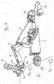
- Figure 3 is a perspective view from above of the holder 1.
- the link 2 is in a coupling position ready for connection to a trailer or implement 1b.
- the link indication rod 8 is disconnected from the second element 4.
- the second element 4 comprises two parallel plates which are attached to the link 2 by a pivot pin.
- Link indication rod 8 is provided with a hook at one end which is connectable to a cross bar 9 on the second element 4. The other end of the rod is pivotably attached to the link 2 and held in place with a fixing pin.
- the link indication rod 8 can be pivoted and stored parallel to the link 2 out of the way.
- link 2 is retracted and gravity acts to pivot the link downwards and in doing so pulls second element 4 away from the first element 3.
Landscapes
- Life Sciences & Earth Sciences (AREA)
- Zoology (AREA)
- Engineering & Computer Science (AREA)
- Mechanical Engineering (AREA)
- Soil Sciences (AREA)
- Environmental Sciences (AREA)
- Agricultural Machines (AREA)
Description
- This invention relates to a link holder on a vehicle or machine. More specifically, this invention relates to a top link holder on a vehicle or machine.
- Vehicles or machines such as agricultural tractors are provided with hitch devices to enable an implement to be attached to them.
- On an agricultural tractor, for example, a top link holder is provided which can facilitate the handling of a top link of a three-point-hitch device on the rear of a tractor. The top link is pivotally attached to the tractor to allow movement about a horizontal axis. Movement about a vertical axis may also be possible. If the top link is not in use a top link holder holds the top link in a parking position which is a substantially vertical position so that it cannot move about the vertical or horizontal axis. If the operator has to couple the top link to an implement, the top link is released from the holder and the top link is pulled downwards to a coupling point of the implement. The top link is heavy and if the operator drops the top link during coupling the link can cause damage to the operator or a part of the tractor, or be damaged itself.
- Typically, top link holders comprise a crude metal rod fixed to a part of the tractor and which extends in a substantially vertical direction. The rod is provided with a simple securing mechanism to secure the top link to the rod in the parking position. The securing mechanism may be a hook for example. To release the top link, the securing mechanism is released and the operator pulls and supports the top link to lower it safely. Other known top link holders comprise a metal rod which is movably fixed to the tractor and is provided with a ball element and the hook of the top link can be attached to hold the top link in the parking position.
EP1982854 discloses another example of a link holder. - It is an aim of the present invention to provide an improved link holder which improves the safety and ease of moving an extendible link.
- According to the invention there is provided a link holder for controlling movement of an extendible pivotable link on a vehicle or machine, said holder comprising a first elongated element and a second elongated element which are moveably connected together at each end, wherein a free end of the first elongated element is attachable to the vehicle or machine and a free end of the second element is pivotally attachable to the link, said holder further comprising a connecting element which connects an extendible part of the link to the second element, wherein the link is pivotally raised by extending the link and pivotally lowered by retracting the link.
- In this way the link is automatically pivoted to a parking position upon extension of the extendible part of the link. By parking position it is meant a link storage position for when the top link is not in use in which the link is secured in a substantially vertical position. Preferably, the link holder is attached to a rail on the vehicle or machine. The rail is preferably formed so that the first element can pivot about a fixed point in the rail and (if necessary) can move linearly along the rail. The link holder may be provided with serrated edges to engage with a protrusion on the first element. This way the link can be held at a desired position and if the operator removes the connecting element from the extendible part of the link, the link will not drop to the ground but be held within the serrations. The connecting element is preferably a link indication rod associated with the link. More preferably, the link is moved into a parking position by extending the link.
- The link is preferably a top link. More preferably, the vehicle is an agricultural tractor.
- The invention will now be described, by way of example only, with reference to the following drawings in which:
- Figure 1
- is side view of a link holder in accordance with the invention,
- Figure 2
- is side view of the link holder of
figure 1 in a parking position, and - Figure 3
- is a perspective view of the link holder of
figure 1 . - In
figure 1 a link holder 1 is shown which is attached to alink 2. Thelink 2 is an extendible link on a machine or vehicle, such as a top link which is mounted on the rear of an agricultural tractor 1a. The link is provided with ahook 2a which can be extended or retracted. Thelink 2 is pivotably attached to the vehicle, or machine atpivot point 5b. The tractor 1a is provided with twoother pivot points elongated element 3 and a secondelongated element 4 which are moveably connected together at each end. The free end of thesecond element 4 is pivotably attached to thelink 2 and the free end of thefirst element 3 is moveably connected to the tractor by way of arail 6. Thefirst element 3 is provided with two guiding elements 7a, 7b which slide within therail 6.Rail 6 comprises two parallel plates having cut out portions. Each of the plates has a linear portion 6a and acurved portion 6b which allows both linear movement and pivotal movement of thefirst element 3. The outer edges ofcurved portions 6b are serrated 10, so that a notch, ornotches 11 located on thefirst element 3 can engage with the serrations to as a safety feature to prevent the link falling. Thelink 2 is provided with a link indication rod 8 (as is common with extendible links) which shows the operator at a glance how much thelink 2 is extended. - Depending on the
pivot point link 2 may be partly extended so that thelink indication rod 8 can be attached to thesecond element 4 as shown infigure 1 . If the link is attached to a different pivot point it is possible to connect the extendible part of the top link to the second element when in a fully retracted position. The position oflink 2 infigure 1 is somewhere between the parking position in which the link is in a substantially vertical position and a coupling position in which the link is in a substantially horizontal position for attachment to a trailer, or implement. - To move the
link 2 from a coupling position to the parking position, the link is decoupled from the trailer or implement and thelink indication rod 8 attached to thesecond element 4. Aslink 2 is extended a force is exerted on thesecond element 4 causing it to move towardsfirst element 3 and causingfirst element 3 to pivot anti clockwise about guiding element 7a and forlink 2 pivot anti clockwise aboutpivot point 5b.First element 3 moves upward in thecurved portion 6b of therail 6 and lifts thelink indication rod 8 and thus thelink 2. Sincelink 2 is pivotably attached to the tractor,first element 3 initially pivots about guiding element 7a inrail 6 as guiding element 7b moves along thecurved portion 6b. Asfirst element 3 moves,second element 4 also moves and thus liftslink 2. If the link is coupled to the tractor onpivot point first element 3 is pivoted until guiding element 7b is positioned above guiding element 7a, thefirst element 3 slides vertically upwards along linear portion 6a ofrail 6 to bring thelink 2 to the parking position. The distance the first element slides up the linear portion will depend on the amount that thelink 2 is extended. If thelink 2 is coupled to the tractor onpivot point 5c and it is necessary to bring thelink 2 to the parking position, thefirst element 3 slides within thecurved portion 6b of therail 6 and does not need to slide within the linear part 6a.Figure 2 shows thelink 2 attached to the tractor bypivot point 5a in the parking position in which the link is in the fully extended position. In order for thelink 2 to be in the parking position,first element 3 slides to the upper end of therail 6. If the link was less extended, thefirst element 3 would not be able to slide to the upper end of therail 6 and thus in the parking position, the link would be at a greater angle to the vertical than that of the position shown infigure 2 . - To move from the parking position to the coupling position, the rod is attached to the link and the notch or
notches 11 on thefirst element 3 must be released with the serrations onrail 6 then the operator can retract thelink 2 and thereby the link moves automatically to the coupling position. If necessary thelink 2 can be stored in a desired height by latching the notch ornotches 11 with serrations onrail 6. -
Figure 3 is a perspective view from above of the holder 1. Thelink 2 is in a coupling position ready for connection to a trailer or implement 1b. Thelink indication rod 8 is disconnected from thesecond element 4. Forlink 2 to be held in that position it is necessary that the notch ornotches 11 on thefirst element 3 are engaged with theserrations 10 onrail 6. Thesecond element 4 comprises two parallel plates which are attached to thelink 2 by a pivot pin.Link indication rod 8 is provided with a hook at one end which is connectable to a cross bar 9 on thesecond element 4. The other end of the rod is pivotably attached to thelink 2 and held in place with a fixing pin. When not connected to thesecond element 4, thelink indication rod 8 can be pivoted and stored parallel to thelink 2 out of the way. - To move the link from the parking position shown in
figure 2 to the coupling position shown infigure 3 ,link 2 is retracted and gravity acts to pivot the link downwards and in doing so pullssecond element 4 away from thefirst element 3.
Claims (8)
- A link holder (1) for controlling movement of an extendible pivotable link (2) on a vehicle or machine, said holder (1) comprising a first elongated element (3) and a second elongated element (4) which are moveably connected together at each end, characterised in that a free end of the first elongated element (3) is attachable to the vehicle or machine and a free end of the second element (4) is pivotably attachable to the link (2), said holder (1) further comprising a connecting element (8) which connects an extendible part of the link (2) to the second element (4), wherein the link (2) is privotally raised by extending the link (2) and pivotally lowered by retracting the link (2).
- A link holder (1) as claimed in claim 1 where the link (2) is pivotable to a generally upright position.
- A link holder (1) as claimed in claim 1 or claim 2 wherein the first element (3) is attached to a rail (6) on the vehicle or machine.
- A link holder (1) as claimed in claim 3 wherein the rail (6) allows linear and/or pivotal movement of the first element (3).
- A link holder (1) as claimed in claim 3 or claim 4 wherein the rail (6) is provided with serrated edges (10) to engage with a protrusion (11) on the first element (3) to secure the link (2) at a desired position.
- A link holder (1) as claimed in any preceding claim wherein the connecting element (8) is a link indication rod.
- A link holder (1) as claimed in any preceding claim for use on an agricultural tractor.
- A link holder (1) as claimed in any preceding claim for a top link.
Applications Claiming Priority (3)
| Application Number | Priority Date | Filing Date | Title |
|---|---|---|---|
| GBGB1121552.2A GB201121552D0 (en) | 2011-12-15 | 2011-12-15 | Link holder on a vehicle or machine |
| GB201201667A GB201201667D0 (en) | 2011-12-15 | 2012-01-31 | Link holder |
| PCT/EP2012/070474 WO2013087260A1 (en) | 2011-12-15 | 2012-10-16 | Link holder |
Publications (2)
| Publication Number | Publication Date |
|---|---|
| EP2790484A1 EP2790484A1 (en) | 2014-10-22 |
| EP2790484B1 true EP2790484B1 (en) | 2016-06-08 |
Family
ID=45560496
Family Applications (2)
| Application Number | Title | Priority Date | Filing Date |
|---|---|---|---|
| EP12735808.3A Not-in-force EP2790483B1 (en) | 2011-12-15 | 2012-06-26 | Link holder on a vehicle or machine |
| EP12775010.7A Not-in-force EP2790484B1 (en) | 2011-12-15 | 2012-10-16 | Link holder |
Family Applications Before (1)
| Application Number | Title | Priority Date | Filing Date |
|---|---|---|---|
| EP12735808.3A Not-in-force EP2790483B1 (en) | 2011-12-15 | 2012-06-26 | Link holder on a vehicle or machine |
Country Status (3)
| Country | Link |
|---|---|
| EP (2) | EP2790483B1 (en) |
| GB (2) | GB201121552D0 (en) |
| WO (2) | WO2013087233A1 (en) |
Families Citing this family (4)
| Publication number | Priority date | Publication date | Assignee | Title |
|---|---|---|---|---|
| GB201617032D0 (en) | 2016-10-07 | 2016-11-23 | Agco International Gmbh | Link holder |
| IT201700007877A1 (en) * | 2017-01-25 | 2018-07-25 | Aries S R L | ATTACK WITH THREE POINTS FOR AGRICULTURAL MACHINES |
| EP3571908B1 (en) * | 2018-05-23 | 2022-08-10 | AGCO International GmbH | Folding hitch |
| DE202020001522U1 (en) * | 2020-04-11 | 2020-04-29 | Rudolf Gehrke | Holding device for a top link |
Family Cites Families (7)
| Publication number | Priority date | Publication date | Assignee | Title |
|---|---|---|---|---|
| US2755722A (en) * | 1952-12-03 | 1956-07-24 | Case Co J I | Tractor mounted rear tool bar |
| DE2217762A1 (en) * | 1972-04-13 | 1973-10-25 | Kloeckner Humboldt Deutz Ag | DEVICE MOUNTING DEVICE |
| DE3812198A1 (en) * | 1988-04-13 | 1989-10-26 | Walterscheid Gmbh Jean | THREE-POINT ATTACHMENT DEVICE |
| DE3839506C1 (en) * | 1988-11-23 | 1989-10-12 | J I Case Gmbh, 4040 Neuss, De | Device for fixing the unused upper link of a hydraulic three-point mounting apparatus on farm tractors |
| DE3839522C1 (en) * | 1988-11-23 | 1989-11-30 | J I Case Gmbh, 4040 Neuss, De | Device for fixing the unused upper link of a hydraulic three-point mounting apparatus on farm tractors |
| GB2247148A (en) * | 1990-08-22 | 1992-02-26 | Charterhouse Turf Machinery Li | An improved connection between an implement and a tractor |
| DE102007019128A1 (en) * | 2007-04-20 | 2008-10-23 | Deere & Company, Moline | Handlebar device for a three-point hitch device |
-
2011
- 2011-12-15 GB GBGB1121552.2A patent/GB201121552D0/en not_active Ceased
-
2012
- 2012-01-31 GB GB201201667A patent/GB201201667D0/en not_active Ceased
- 2012-06-26 EP EP12735808.3A patent/EP2790483B1/en not_active Not-in-force
- 2012-06-26 WO PCT/EP2012/062373 patent/WO2013087233A1/en not_active Ceased
- 2012-10-16 WO PCT/EP2012/070474 patent/WO2013087260A1/en not_active Ceased
- 2012-10-16 EP EP12775010.7A patent/EP2790484B1/en not_active Not-in-force
Non-Patent Citations (1)
| Title |
|---|
| None * |
Also Published As
| Publication number | Publication date |
|---|---|
| GB201121552D0 (en) | 2012-01-25 |
| WO2013087233A1 (en) | 2013-06-20 |
| WO2013087260A1 (en) | 2013-06-20 |
| EP2790483A1 (en) | 2014-10-22 |
| EP2790484A1 (en) | 2014-10-22 |
| GB201201667D0 (en) | 2012-03-14 |
| EP2790483B1 (en) | 2021-03-03 |
Similar Documents
| Publication | Publication Date | Title |
|---|---|---|
| EP1955974B1 (en) | Automatically deployable boom extension and method of deploying same | |
| EP2100757B1 (en) | Tractor hitches | |
| US20100289249A1 (en) | Hitch Apparatuses and Methods of Securing Hitch Apparatuses | |
| WO2013087260A1 (en) | Link holder | |
| EP2103458A1 (en) | A vehicle hitch | |
| JP7274791B2 (en) | lawn mower | |
| CN106114090B (en) | Traction coupling assembly and traction system | |
| US7878524B1 (en) | Gooseneck trailer hitch convertible to a lifting boom | |
| JP6419621B2 (en) | Bogie connection structure | |
| EP2340699B1 (en) | Linkage attachment means for a vehicle | |
| EP2399442A1 (en) | A tow bar having a pin with automatic coupling | |
| US10753063B2 (en) | Front loader | |
| US10508407B2 (en) | Front loader | |
| EP2790935B1 (en) | Towing attachment | |
| US20150030425A1 (en) | Front loader arrangement | |
| JP6856920B2 (en) | Mower | |
| US4018451A (en) | Tractor three-point connection having leaf springs | |
| EP1836062B1 (en) | Retractable tow hitch | |
| US9622410B2 (en) | Material collection parking system | |
| US1453059A (en) | Coupling | |
| US10420273B2 (en) | Releasable lock for rear folding implement wings | |
| JP2004130993A (en) | Sliding type coupler device | |
| US20050023012A1 (en) | Three point hitch | |
| GB1601738A (en) | Implement trailer | |
| JP2009159915A (en) | Rice transplanter |
Legal Events
| Date | Code | Title | Description |
|---|---|---|---|
| PUAI | Public reference made under article 153(3) epc to a published international application that has entered the european phase |
Free format text: ORIGINAL CODE: 0009012 |
|
| 17P | Request for examination filed |
Effective date: 20140715 |
|
| AK | Designated contracting states |
Kind code of ref document: A1 Designated state(s): AL AT BE BG CH CY CZ DE DK EE ES FI FR GB GR HR HU IE IS IT LI LT LU LV MC MK MT NL NO PL PT RO RS SE SI SK SM TR |
|
| DAX | Request for extension of the european patent (deleted) | ||
| GRAP | Despatch of communication of intention to grant a patent |
Free format text: ORIGINAL CODE: EPIDOSNIGR1 |
|
| INTG | Intention to grant announced |
Effective date: 20160210 |
|
| GRAS | Grant fee paid |
Free format text: ORIGINAL CODE: EPIDOSNIGR3 |
|
| GRAA | (expected) grant |
Free format text: ORIGINAL CODE: 0009210 |
|
| AK | Designated contracting states |
Kind code of ref document: B1 Designated state(s): AL AT BE BG CH CY CZ DE DK EE ES FI FR GB GR HR HU IE IS IT LI LT LU LV MC MK MT NL NO PL PT RO RS SE SI SK SM TR |
|
| REG | Reference to a national code |
Ref country code: GB Ref legal event code: FG4D |
|
| REG | Reference to a national code |
Ref country code: CH Ref legal event code: EP |
|
| REG | Reference to a national code |
Ref country code: IE Ref legal event code: FG4D |
|
| REG | Reference to a national code |
Ref country code: AT Ref legal event code: REF Ref document number: 804534 Country of ref document: AT Kind code of ref document: T Effective date: 20160715 |
|
| REG | Reference to a national code |
Ref country code: DE Ref legal event code: R096 Ref document number: 602012019424 Country of ref document: DE |
|
| REG | Reference to a national code |
Ref country code: LT Ref legal event code: MG4D |
|
| REG | Reference to a national code |
Ref country code: NL Ref legal event code: MP Effective date: 20160608 |
|
| REG | Reference to a national code |
Ref country code: FR Ref legal event code: PLFP Year of fee payment: 5 |
|
| PG25 | Lapsed in a contracting state [announced via postgrant information from national office to epo] |
Ref country code: FI Free format text: LAPSE BECAUSE OF FAILURE TO SUBMIT A TRANSLATION OF THE DESCRIPTION OR TO PAY THE FEE WITHIN THE PRESCRIBED TIME-LIMIT Effective date: 20160608 Ref country code: LT Free format text: LAPSE BECAUSE OF FAILURE TO SUBMIT A TRANSLATION OF THE DESCRIPTION OR TO PAY THE FEE WITHIN THE PRESCRIBED TIME-LIMIT Effective date: 20160608 Ref country code: NO Free format text: LAPSE BECAUSE OF FAILURE TO SUBMIT A TRANSLATION OF THE DESCRIPTION OR TO PAY THE FEE WITHIN THE PRESCRIBED TIME-LIMIT Effective date: 20160908 |
|
| REG | Reference to a national code |
Ref country code: AT Ref legal event code: MK05 Ref document number: 804534 Country of ref document: AT Kind code of ref document: T Effective date: 20160608 |
|
| PG25 | Lapsed in a contracting state [announced via postgrant information from national office to epo] |
Ref country code: SE Free format text: LAPSE BECAUSE OF FAILURE TO SUBMIT A TRANSLATION OF THE DESCRIPTION OR TO PAY THE FEE WITHIN THE PRESCRIBED TIME-LIMIT Effective date: 20160608 Ref country code: NL Free format text: LAPSE BECAUSE OF FAILURE TO SUBMIT A TRANSLATION OF THE DESCRIPTION OR TO PAY THE FEE WITHIN THE PRESCRIBED TIME-LIMIT Effective date: 20160608 Ref country code: HR Free format text: LAPSE BECAUSE OF FAILURE TO SUBMIT A TRANSLATION OF THE DESCRIPTION OR TO PAY THE FEE WITHIN THE PRESCRIBED TIME-LIMIT Effective date: 20160608 Ref country code: ES Free format text: LAPSE BECAUSE OF FAILURE TO SUBMIT A TRANSLATION OF THE DESCRIPTION OR TO PAY THE FEE WITHIN THE PRESCRIBED TIME-LIMIT Effective date: 20160608 Ref country code: GR Free format text: LAPSE BECAUSE OF FAILURE TO SUBMIT A TRANSLATION OF THE DESCRIPTION OR TO PAY THE FEE WITHIN THE PRESCRIBED TIME-LIMIT Effective date: 20160909 Ref country code: LV Free format text: LAPSE BECAUSE OF FAILURE TO SUBMIT A TRANSLATION OF THE DESCRIPTION OR TO PAY THE FEE WITHIN THE PRESCRIBED TIME-LIMIT Effective date: 20160608 Ref country code: RS Free format text: LAPSE BECAUSE OF FAILURE TO SUBMIT A TRANSLATION OF THE DESCRIPTION OR TO PAY THE FEE WITHIN THE PRESCRIBED TIME-LIMIT Effective date: 20160608 |
|
| PG25 | Lapsed in a contracting state [announced via postgrant information from national office to epo] |
Ref country code: RO Free format text: LAPSE BECAUSE OF FAILURE TO SUBMIT A TRANSLATION OF THE DESCRIPTION OR TO PAY THE FEE WITHIN THE PRESCRIBED TIME-LIMIT Effective date: 20160608 Ref country code: IS Free format text: LAPSE BECAUSE OF FAILURE TO SUBMIT A TRANSLATION OF THE DESCRIPTION OR TO PAY THE FEE WITHIN THE PRESCRIBED TIME-LIMIT Effective date: 20161008 Ref country code: SK Free format text: LAPSE BECAUSE OF FAILURE TO SUBMIT A TRANSLATION OF THE DESCRIPTION OR TO PAY THE FEE WITHIN THE PRESCRIBED TIME-LIMIT Effective date: 20160608 Ref country code: EE Free format text: LAPSE BECAUSE OF FAILURE TO SUBMIT A TRANSLATION OF THE DESCRIPTION OR TO PAY THE FEE WITHIN THE PRESCRIBED TIME-LIMIT Effective date: 20160608 Ref country code: CZ Free format text: LAPSE BECAUSE OF FAILURE TO SUBMIT A TRANSLATION OF THE DESCRIPTION OR TO PAY THE FEE WITHIN THE PRESCRIBED TIME-LIMIT Effective date: 20160608 |
|
| PG25 | Lapsed in a contracting state [announced via postgrant information from national office to epo] |
Ref country code: BE Free format text: LAPSE BECAUSE OF NON-PAYMENT OF DUE FEES Effective date: 20160608 Ref country code: PT Free format text: LAPSE BECAUSE OF FAILURE TO SUBMIT A TRANSLATION OF THE DESCRIPTION OR TO PAY THE FEE WITHIN THE PRESCRIBED TIME-LIMIT Effective date: 20161010 Ref country code: AT Free format text: LAPSE BECAUSE OF FAILURE TO SUBMIT A TRANSLATION OF THE DESCRIPTION OR TO PAY THE FEE WITHIN THE PRESCRIBED TIME-LIMIT Effective date: 20160608 Ref country code: SM Free format text: LAPSE BECAUSE OF FAILURE TO SUBMIT A TRANSLATION OF THE DESCRIPTION OR TO PAY THE FEE WITHIN THE PRESCRIBED TIME-LIMIT Effective date: 20160608 Ref country code: PL Free format text: LAPSE BECAUSE OF FAILURE TO SUBMIT A TRANSLATION OF THE DESCRIPTION OR TO PAY THE FEE WITHIN THE PRESCRIBED TIME-LIMIT Effective date: 20160608 |
|
| REG | Reference to a national code |
Ref country code: DE Ref legal event code: R097 Ref document number: 602012019424 Country of ref document: DE |
|
| PLBE | No opposition filed within time limit |
Free format text: ORIGINAL CODE: 0009261 |
|
| STAA | Information on the status of an ep patent application or granted ep patent |
Free format text: STATUS: NO OPPOSITION FILED WITHIN TIME LIMIT |
|
| 26N | No opposition filed |
Effective date: 20170309 |
|
| PG25 | Lapsed in a contracting state [announced via postgrant information from national office to epo] |
Ref country code: SI Free format text: LAPSE BECAUSE OF FAILURE TO SUBMIT A TRANSLATION OF THE DESCRIPTION OR TO PAY THE FEE WITHIN THE PRESCRIBED TIME-LIMIT Effective date: 20160608 Ref country code: DK Free format text: LAPSE BECAUSE OF FAILURE TO SUBMIT A TRANSLATION OF THE DESCRIPTION OR TO PAY THE FEE WITHIN THE PRESCRIBED TIME-LIMIT Effective date: 20160608 |
|
| REG | Reference to a national code |
Ref country code: CH Ref legal event code: PL |
|
| GBPC | Gb: european patent ceased through non-payment of renewal fee |
Effective date: 20161016 |
|
| REG | Reference to a national code |
Ref country code: IE Ref legal event code: MM4A |
|
| PG25 | Lapsed in a contracting state [announced via postgrant information from national office to epo] |
Ref country code: CH Free format text: LAPSE BECAUSE OF NON-PAYMENT OF DUE FEES Effective date: 20161031 Ref country code: LI Free format text: LAPSE BECAUSE OF NON-PAYMENT OF DUE FEES Effective date: 20161031 Ref country code: GB Free format text: LAPSE BECAUSE OF NON-PAYMENT OF DUE FEES Effective date: 20161016 |
|
| PG25 | Lapsed in a contracting state [announced via postgrant information from national office to epo] |
Ref country code: LU Free format text: LAPSE BECAUSE OF NON-PAYMENT OF DUE FEES Effective date: 20161016 |
|
| REG | Reference to a national code |
Ref country code: FR Ref legal event code: PLFP Year of fee payment: 6 |
|
| PG25 | Lapsed in a contracting state [announced via postgrant information from national office to epo] |
Ref country code: IE Free format text: LAPSE BECAUSE OF NON-PAYMENT OF DUE FEES Effective date: 20161016 |
|
| PG25 | Lapsed in a contracting state [announced via postgrant information from national office to epo] |
Ref country code: HU Free format text: LAPSE BECAUSE OF FAILURE TO SUBMIT A TRANSLATION OF THE DESCRIPTION OR TO PAY THE FEE WITHIN THE PRESCRIBED TIME-LIMIT; INVALID AB INITIO Effective date: 20121016 |
|
| PG25 | Lapsed in a contracting state [announced via postgrant information from national office to epo] |
Ref country code: CY Free format text: LAPSE BECAUSE OF FAILURE TO SUBMIT A TRANSLATION OF THE DESCRIPTION OR TO PAY THE FEE WITHIN THE PRESCRIBED TIME-LIMIT Effective date: 20160608 Ref country code: MK Free format text: LAPSE BECAUSE OF FAILURE TO SUBMIT A TRANSLATION OF THE DESCRIPTION OR TO PAY THE FEE WITHIN THE PRESCRIBED TIME-LIMIT Effective date: 20160608 Ref country code: MC Free format text: LAPSE BECAUSE OF FAILURE TO SUBMIT A TRANSLATION OF THE DESCRIPTION OR TO PAY THE FEE WITHIN THE PRESCRIBED TIME-LIMIT Effective date: 20160608 Ref country code: MT Free format text: LAPSE BECAUSE OF NON-PAYMENT OF DUE FEES Effective date: 20161031 |
|
| PG25 | Lapsed in a contracting state [announced via postgrant information from national office to epo] |
Ref country code: BG Free format text: LAPSE BECAUSE OF FAILURE TO SUBMIT A TRANSLATION OF THE DESCRIPTION OR TO PAY THE FEE WITHIN THE PRESCRIBED TIME-LIMIT Effective date: 20160608 |
|
| REG | Reference to a national code |
Ref country code: FR Ref legal event code: PLFP Year of fee payment: 7 |
|
| PG25 | Lapsed in a contracting state [announced via postgrant information from national office to epo] |
Ref country code: TR Free format text: LAPSE BECAUSE OF FAILURE TO SUBMIT A TRANSLATION OF THE DESCRIPTION OR TO PAY THE FEE WITHIN THE PRESCRIBED TIME-LIMIT Effective date: 20160608 Ref country code: AL Free format text: LAPSE BECAUSE OF FAILURE TO SUBMIT A TRANSLATION OF THE DESCRIPTION OR TO PAY THE FEE WITHIN THE PRESCRIBED TIME-LIMIT Effective date: 20160608 |
|
| PGFP | Annual fee paid to national office [announced via postgrant information from national office to epo] |
Ref country code: DE Payment date: 20211020 Year of fee payment: 10 |
|
| PGFP | Annual fee paid to national office [announced via postgrant information from national office to epo] |
Ref country code: IT Payment date: 20211022 Year of fee payment: 10 Ref country code: FR Payment date: 20211022 Year of fee payment: 10 |
|
| REG | Reference to a national code |
Ref country code: DE Ref legal event code: R119 Ref document number: 602012019424 Country of ref document: DE |
|
| PG25 | Lapsed in a contracting state [announced via postgrant information from national office to epo] |
Ref country code: FR Free format text: LAPSE BECAUSE OF NON-PAYMENT OF DUE FEES Effective date: 20221031 Ref country code: DE Free format text: LAPSE BECAUSE OF NON-PAYMENT OF DUE FEES Effective date: 20230503 |
|
| PG25 | Lapsed in a contracting state [announced via postgrant information from national office to epo] |
Ref country code: IT Free format text: LAPSE BECAUSE OF NON-PAYMENT OF DUE FEES Effective date: 20221016 |