EP2789916A1 - Method for operating a combustion chamber and combustion chamber - Google Patents
Method for operating a combustion chamber and combustion chamber Download PDFInfo
- Publication number
- EP2789916A1 EP2789916A1 EP14158597.6A EP14158597A EP2789916A1 EP 2789916 A1 EP2789916 A1 EP 2789916A1 EP 14158597 A EP14158597 A EP 14158597A EP 2789916 A1 EP2789916 A1 EP 2789916A1
- Authority
- EP
- European Patent Office
- Prior art keywords
- fuel
- combustion chamber
- supply duct
- carrier air
- turbine
- Prior art date
- Legal status (The legal status is an assumption and is not a legal conclusion. Google has not performed a legal analysis and makes no representation as to the accuracy of the status listed.)
- Granted
Links
Images

Classifications
-
- F—MECHANICAL ENGINEERING; LIGHTING; HEATING; WEAPONS; BLASTING
- F02—COMBUSTION ENGINES; HOT-GAS OR COMBUSTION-PRODUCT ENGINE PLANTS
- F02C—GAS-TURBINE PLANTS; AIR INTAKES FOR JET-PROPULSION PLANTS; CONTROLLING FUEL SUPPLY IN AIR-BREATHING JET-PROPULSION PLANTS
- F02C7/00—Features, components parts, details or accessories, not provided for in, or of interest apart form groups F02C1/00 - F02C6/00; Air intakes for jet-propulsion plants
- F02C7/04—Air intakes for gas-turbine plants or jet-propulsion plants
- F02C7/057—Control or regulation
-
- F—MECHANICAL ENGINEERING; LIGHTING; HEATING; WEAPONS; BLASTING
- F23—COMBUSTION APPARATUS; COMBUSTION PROCESSES
- F23N—REGULATING OR CONTROLLING COMBUSTION
- F23N1/00—Regulating fuel supply
- F23N1/02—Regulating fuel supply conjointly with air supply
-
- F—MECHANICAL ENGINEERING; LIGHTING; HEATING; WEAPONS; BLASTING
- F23—COMBUSTION APPARATUS; COMBUSTION PROCESSES
- F23N—REGULATING OR CONTROLLING COMBUSTION
- F23N1/00—Regulating fuel supply
- F23N1/02—Regulating fuel supply conjointly with air supply
- F23N1/022—Regulating fuel supply conjointly with air supply using electronic means
-
- F—MECHANICAL ENGINEERING; LIGHTING; HEATING; WEAPONS; BLASTING
- F23—COMBUSTION APPARATUS; COMBUSTION PROCESSES
- F23R—GENERATING COMBUSTION PRODUCTS OF HIGH PRESSURE OR HIGH VELOCITY, e.g. GAS-TURBINE COMBUSTION CHAMBERS
- F23R3/00—Continuous combustion chambers using liquid or gaseous fuel
- F23R3/02—Continuous combustion chambers using liquid or gaseous fuel characterised by the air-flow or gas-flow configuration
- F23R3/26—Controlling the air flow
-
- F—MECHANICAL ENGINEERING; LIGHTING; HEATING; WEAPONS; BLASTING
- F23—COMBUSTION APPARATUS; COMBUSTION PROCESSES
- F23R—GENERATING COMBUSTION PRODUCTS OF HIGH PRESSURE OR HIGH VELOCITY, e.g. GAS-TURBINE COMBUSTION CHAMBERS
- F23R3/00—Continuous combustion chambers using liquid or gaseous fuel
- F23R3/28—Continuous combustion chambers using liquid or gaseous fuel characterised by the fuel supply
- F23R3/34—Feeding into different combustion zones
- F23R3/346—Feeding into different combustion zones for staged combustion
-
- F—MECHANICAL ENGINEERING; LIGHTING; HEATING; WEAPONS; BLASTING
- F05—INDEXING SCHEMES RELATING TO ENGINES OR PUMPS IN VARIOUS SUBCLASSES OF CLASSES F01-F04
- F05D—INDEXING SCHEME FOR ASPECTS RELATING TO NON-POSITIVE-DISPLACEMENT MACHINES OR ENGINES, GAS-TURBINES OR JET-PROPULSION PLANTS
- F05D2240/00—Components
- F05D2240/35—Combustors or associated equipment
-
- F—MECHANICAL ENGINEERING; LIGHTING; HEATING; WEAPONS; BLASTING
- F23—COMBUSTION APPARATUS; COMBUSTION PROCESSES
- F23N—REGULATING OR CONTROLLING COMBUSTION
- F23N2221/00—Pretreatment or prehandling
- F23N2221/10—Analysing fuel properties, e.g. density, calorific
-
- F—MECHANICAL ENGINEERING; LIGHTING; HEATING; WEAPONS; BLASTING
- F23—COMBUSTION APPARATUS; COMBUSTION PROCESSES
- F23R—GENERATING COMBUSTION PRODUCTS OF HIGH PRESSURE OR HIGH VELOCITY, e.g. GAS-TURBINE COMBUSTION CHAMBERS
- F23R2900/00—Special features of, or arrangements for continuous combustion chambers; Combustion processes therefor
- F23R2900/03341—Sequential combustion chambers or burners
Definitions
- the present disclosure relates to a method for operating a combustion chamber and a combustion chamber.
- combustion chamber is a combustion chamber of a gas turbine.
- Gas turbines include a compressor, a combustion chamber and a turbine to expand the hot gas generated in the combustion chamber.
- gas turbines can have a second combustion chamber downstream of the turbine and a second turbine downstream of the second combustion chamber.
- the combustion chamber and second combustion chamber (when provided) are supplied with air from the compressor and fuel; the fuel is combusted to generate the hot gas.
- the fuel is natural gas
- its composition and features can largely change over time.
- the amount of nitrogen inert component because it does not take part in the combustion process
- the fuel mass flow injected into the combustion chamber can largely vary when the features of the fuel vary also if the gas turbine load is kept constant or substantially constant.
- An aspect of the disclosure includes providing a method and a gas turbine that allow a correct fuel jet penetration also when the fuel composition changes.
- Another aspect of the disclosure includes providing a method and a gas turbine that allow correct mixing, reduced emissions and efficient operation also in case the fuel composition changes over time.
- Figure 1 shows a gas turbine 1 having a compressor 2, a combustion chamber 3 and a turbine 4.
- the compressor 2 compresses air that is supplied into the combustion chamber 3 where it is mixed with a fuel such as natural gas; this mixture is combusted to generate hot gas that is expanded in the turbine 4.
- Figure 2 shows an example in which the gas turbine 1 has, downstream of the turbine 4, a second combustion chamber 5 and a second turbine 6.
- a fuel such as natural gas is injected into the exhaust gas partly expanded in the turbine 4 to generate hot gas that is expanded in the turbine 6.
- the combustion chambers 3 and 5 can have the same or similar features or can have different features. In the following specific reference to the combustion chamber 5 is done, the same considerations apply to the combustion chamber 3 independently of the fact that the combustion chambers 3 and 5 have the same, similar or different features.
- the combustion chamber 5 comprises a body 10 defining for example a rectangular, square or trapezoidal duct 11.
- the combustion chamber 5 has a fuel supply duct 14 for supplying a fuel such as natural gas into the body 10 and a carrier air supply duct 15 for supplying air into the body 10.
- Carrier air is an air mass flow that confines the fuel jet and adds momentum to it for enhanced penetration. It also shields the fuel from too rapid hot gas entrainment and delay the auto-ignition
- the combustion chamber 5 further comprises an adjusting system 17 for adjusting the carrier air mass flow supplied into the body 10 according to the features of the fuel.
- the fuel supply duct 14 and the carrier air supply duct 15 are connected to at least a common nozzle 19; in other words the flow through both the fuel supply duct 14 and the air supply duct 15 is injected into the body 10 through nozzles 19.
- the fuel supply duct 14 has openings 20 facing the central part the nozzles 19 and the air supply duct 15 has passages 21 around the apertures 20 over the border of the nozzles 19.
- the adjusting system 17 is arranged to keep the momentum of the fuel and carrier air injected through the common nozzles 19 substantially constant, preferably when the load of the gas turbine is substantially constant.
- a lance 24 is provided; the lance 24 protrudes into the body 10 and has the common nozzles 19.
- One or more such common nozzles 19 can be provided.
- the lance 24 houses the fuel supply duct 14 and the carrier air supply duct 15 and the fuel supply duct 14 and the carrier air supply duct 15 are connected to the common nozzles 19.
- the adjusting system 17 can include a sensor 25 for measuring a characteristic feature of the fuel, a throttling valve 27 connected to the carrier air supply duct 15, and a control unit 28 connected to the sensor 25 and throttling valve 27 for driving the throttling valve 27 on the basis of the characteristic feature measured by the sensor 25.
- the adjusting system can include the apertures 20 and/or the passages 21 having a shape and/or dimension producing an automatic regulation of the air flow when the fuel flow changes.
- the apertures 20 and nozzles 19 can have substantially overlapping axes 27, the area of the apertures 20 perpendicularly to the axes 27 can be smaller than the area of the nozzles 19 perpendicularly to the same axes 27.
- the feature of the fuel can be the mass flow and/or the composition and/or the Wobbe index of the fuel.
- the fuel such as natural gas passes through the fuel supply duct 14; the sensor 25 detects the required feature of the fuel and transmits it to the control unit 28.
- the control unit 28 drives the throttling valve 27 on the basis of the signal received by the sensor 25.
- the throttle valve 27 adjusts the carrier air flow on the basis of the fuel flow. Adjustment can include regulation of the momentum of air and fuel injected according to a prefixed function or to keep them constant.
- the momentum of air and fuel is: M a • V a + M f • V f wherein M a is the mass flow of carrier air, Va is the carrier air velocity at injection, M f is the mass flow of fuel, v f is the fuel velocity at injection.
- the fuel F passes through the fuel supply duct 14 and the carrier air A passes through the air supply duct 15. Thanks to the features of the aperture 20 and passages 21 and nozzles 19 an automatic adjustment of the carrier air flow occurs; in fact, the change of the features of the fuel results in a change of the mass flow of the fuel, because the energy (in terms of Lower Calorific Heating Value) is to be kept substantially constant at a substantially constant load; alternatively the mass flow of the fuel can be regulated according to the load desired.
- Reference M indicates the mixture that is formed by the carrier air A and fuel F; this mixture is formed at the nozzles 19.
- the change of the fuel mass flow influences the air flow through the passage 21 such that an automatic adjustment is achieved.
- the present disclosure also refers to a method for operating a combustion chamber 5.
- the method includes adjusting the carrier air mass flow supplied into the body 10 of the combustion chamber 5 according to the features of the fuel.
- both the fuel and the carrier air are injected via the common nozzles 19.
- the momentum of the fuel and carrier air injected through the common nozzle 19 is kept substantially constant when the load of the gas turbine is substantially constant.
Landscapes
- Engineering & Computer Science (AREA)
- Chemical & Material Sciences (AREA)
- Combustion & Propulsion (AREA)
- Mechanical Engineering (AREA)
- General Engineering & Computer Science (AREA)
- Fluidized-Bed Combustion And Resonant Combustion (AREA)
Abstract
Description
- The present disclosure relates to a method for operating a combustion chamber and a combustion chamber.
- In particular the combustion chamber is a combustion chamber of a gas turbine.
- Gas turbines include a compressor, a combustion chamber and a turbine to expand the hot gas generated in the combustion chamber.
- In addition, the gas turbines can have a second combustion chamber downstream of the turbine and a second turbine downstream of the second combustion chamber.
- The combustion chamber and second combustion chamber (when provided) are supplied with air from the compressor and fuel; the fuel is combusted to generate the hot gas.
- When the fuel is natural gas, its composition and features can largely change over time. For example, the amount of nitrogen (inert component because it does not take part in the combustion process) can largely change over time.
- Since the total energy provided into the combustion chambers (i.e. the Lower Calorific Heating Value of the fuel injected into the combustion chamber) defines the load of the gas turbines, the fuel mass flow injected into the combustion chamber can largely vary when the features of the fuel vary also if the gas turbine load is kept constant or substantially constant.
- When the fuel is injected into the combustion chamber, this large change in fuel mass flow caused by the change of fuel composition can cause a change in the fuel jet penetration into the combustion chamber and, thus, poor mixing, large emissions such as NOx emissions and reduced efficiency.
- An aspect of the disclosure includes providing a method and a gas turbine that allow a correct fuel jet penetration also when the fuel composition changes.
- Another aspect of the disclosure includes providing a method and a gas turbine that allow correct mixing, reduced emissions and efficient operation also in case the fuel composition changes over time.
- These and further aspects are attained by providing a method and a gas turbine in accordance with the accompanying claims.
- Further characteristics and advantages will be more apparent from the description of a preferred but non-exclusive embodiment of the method and gas turbine illustrated by way of non-limiting example in the accompanying drawings, in which:
-
Figures 1 and 2 show different embodiments of gas turbines; -
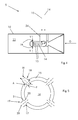
Figures 3 and4 show different embodiments of combustion chambers; -
Figure 5 shows a section through line V-V offigure 4 . - In the following two examples of gas turbines are described first.
-
Figure 1 shows agas turbine 1 having acompressor 2, acombustion chamber 3 and aturbine 4. - The
compressor 2 compresses air that is supplied into thecombustion chamber 3 where it is mixed with a fuel such as natural gas; this mixture is combusted to generate hot gas that is expanded in theturbine 4. -
Figure 2 shows an example in which thegas turbine 1 has, downstream of theturbine 4, asecond combustion chamber 5 and a second turbine 6. - In the second combustion chamber 5 a fuel such as natural gas is injected into the exhaust gas partly expanded in the
turbine 4 to generate hot gas that is expanded in the turbine 6. - The
combustion chambers combustion chamber 5 is done, the same considerations apply to thecombustion chamber 3 independently of the fact that thecombustion chambers - The
combustion chamber 5 comprises abody 10 defining for example a rectangular, square ortrapezoidal duct 11. In addition, thecombustion chamber 5 has afuel supply duct 14 for supplying a fuel such as natural gas into thebody 10 and a carrierair supply duct 15 for supplying air into thebody 10. - Carrier air is an air mass flow that confines the fuel jet and adds momentum to it for enhanced penetration. It also shields the fuel from too rapid hot gas entrainment and delay the auto-ignition
- The
combustion chamber 5 further comprises anadjusting system 17 for adjusting the carrier air mass flow supplied into thebody 10 according to the features of the fuel. - The
fuel supply duct 14 and the carrierair supply duct 15 are connected to at least acommon nozzle 19; in other words the flow through both thefuel supply duct 14 and theair supply duct 15 is injected into thebody 10 throughnozzles 19. Usually, thefuel supply duct 14 hasopenings 20 facing the central part thenozzles 19 and theair supply duct 15 haspassages 21 around theapertures 20 over the border of thenozzles 19. - Advantageously the adjusting
system 17 is arranged to keep the momentum of the fuel and carrier air injected through thecommon nozzles 19 substantially constant, preferably when the load of the gas turbine is substantially constant. - In a preferred embodiment, a
lance 24 is provided; thelance 24 protrudes into thebody 10 and has thecommon nozzles 19. One or more suchcommon nozzles 19 can be provided. Thelance 24 houses thefuel supply duct 14 and the carrierair supply duct 15 and thefuel supply duct 14 and the carrierair supply duct 15 are connected to thecommon nozzles 19. - The
adjusting system 17 can include asensor 25 for measuring a characteristic feature of the fuel, athrottling valve 27 connected to the carrierair supply duct 15, and acontrol unit 28 connected to thesensor 25 andthrottling valve 27 for driving thethrottling valve 27 on the basis of the characteristic feature measured by thesensor 25. - Alternatively, the adjusting system can include the
apertures 20 and/or thepassages 21 having a shape and/or dimension producing an automatic regulation of the air flow when the fuel flow changes. - For example, the
apertures 20 andnozzles 19 can have substantially overlappingaxes 27, the area of theapertures 20 perpendicularly to theaxes 27 can be smaller than the area of thenozzles 19 perpendicularly to thesame axes 27. - In different examples, the feature of the fuel can be the mass flow and/or the composition and/or the Wobbe index of the fuel.
- The operation of the gas turbine is apparent from that described and illustrated and is substantially the following.
- With reference to the example of
figure 3 , the fuel such as natural gas passes through thefuel supply duct 14; thesensor 25 detects the required feature of the fuel and transmits it to thecontrol unit 28. Thecontrol unit 28 drives thethrottling valve 27 on the basis of the signal received by thesensor 25. Thus thethrottle valve 27 adjusts the carrier air flow on the basis of the fuel flow. Adjustment can include regulation of the momentum of air and fuel injected according to a prefixed function or to keep them constant. The momentum of air and fuel is:
- With reference to the example of
figures 4 and 5 , the fuel F passes through thefuel supply duct 14 and the carrier air A passes through theair supply duct 15. Thanks to the features of theaperture 20 andpassages 21 andnozzles 19 an automatic adjustment of the carrier air flow occurs; in fact, the change of the features of the fuel results in a change of the mass flow of the fuel, because the energy (in terms of Lower Calorific Heating Value) is to be kept substantially constant at a substantially constant load; alternatively the mass flow of the fuel can be regulated according to the load desired. Reference M indicates the mixture that is formed by the carrier air A and fuel F; this mixture is formed at thenozzles 19. - The change of the fuel mass flow influences the air flow through the
passage 21 such that an automatic adjustment is achieved. - The present disclosure also refers to a method for operating a
combustion chamber 5. - The method includes adjusting the carrier air mass flow supplied into the
body 10 of thecombustion chamber 5 according to the features of the fuel. - Advantageously both the fuel and the carrier air are injected via the
common nozzles 19. - In addition, the momentum of the fuel and carrier air injected through the
common nozzle 19 is kept substantially constant when the load of the gas turbine is substantially constant. - In practice the materials used and the dimensions can be chosen at will according to requirements and to the state of the art.
-
- 1
- gas turbine
- 2
- compressor
- 3
- combustion chamber
- 4
- turbine
- 5
- combustion chamber
- 6
- turbine
- 10
- body
- 11
- duct
- 14
- fuel supply duct
- 15
- carrier air supply duct
- 17
- adjusting system
- 19
- nozzle
- 20
- aperture
- 21
- passage
- 24
- lance
- 25
- sensor
- 27
- throttling valve
- 28
- control unit
- 29
- axis
- A
- carrier air
- F
- fuel;
- M
- mixture
Claims (12)
- A combustion chamber (5) comprising a body (10) with a fuel supply duct (14) for supplying a fuel (F) into the body (10) and a carrier air supply duct (15) for supplying air (A) into the body (10), characterised by comprising an adjusting system (17) for adjusting the carrier air mass flow supplied into the body (10) according to the features of the fuel (F).
- The combustion chamber (5) of claim 1, characterised in that the fuel supply duct (14) and the carrier air supply duct (15) are connected to at least a common nozzle (19), the at least a common nozzle (19) for injecting both the fuel (F) and the carrier air (A).
- The combustion chamber (5) of claim 2, characterised in that the adjusting system (17) is arranged to keep the momentum of the fuel (F) and carrier air (A) injected through the at least a common nozzle (19) substantially constant.
- The combustion chamber (5) of claim 2, characterised by
comprising a lance (24) that protrudes into the body (10),
the lance (24) has the at least a common nozzle (19), the lance (24) houses the fuel supply duct (14) and the carrier air supply duct (15),
the fuel supply duct (14) and the carrier air supply duct (15) are connected to the common nozzles (19). - The combustion chamber (5) of claim 1, characterised in that the feature of the fuel is the mass flow and/or the composition and/or the Wobbe index.
- The combustion chamber (5) of claim 1 or 3, characterised in that the adjusting system (17) includes
a sensor (25) for measuring a characteristic feature of the fuel (F),
a throttling valve (27) connected to the carrier air supply duct (15),
a control unit (28) connected to the sensor (25) and throttling valve (27) for driving the throttling valve (27) on the basis of the characteristic feature measured by the sensor (25). - The combustion chamber (5) of claim 1, characterised in that it is a part of a gas turbine that includes a compressor (2), a first combustion chamber (3), a first turbine (4).
- The combustion chamber of claim 7, characterised in that downstream of the turbine (4), the gas turbine (1) includes a second combustion chamber (5) supplied with exhaust gases from the turbine (4) and a second turbine (6), the combustion chamber (5) being the first (3) and/or the second combustion chamber (5).
- A method for operating a combustion chamber (5),
the combustion chamber (5) comprising a body (10) with a fuel supply duct (14) for supplying a fuel (F) into the body (10) and a carrier air supply duct (15) for supplying air (A) into the body (10), characterised by
adjusting the carrier air mass flow supplied into the body (10) according to the features of the fuel (F). - The method of claim 9, characterised in that the fuel supply duct (14) and the carrier air supply duct (15) are connected to at least a common nozzle (19),
the method including injecting both the fuel (F) and the carrier air (A) via the at least a common nozzle (19). - The method of claim 10, characterised by maintaining the momentum of the fuel (F) and carrier air (A) injected through the at least a common nozzle (19) substantially constant.
- The method of claim 9, characterised in that the feature of the fuel (F) is the mass flow and/or the composition and/or the Wobbe index.
Priority Applications (1)
| Application Number | Priority Date | Filing Date | Title |
|---|---|---|---|
| EP14158597.6A EP2789916B1 (en) | 2013-04-10 | 2014-03-10 | Combustion chamber |
Applications Claiming Priority (2)
| Application Number | Priority Date | Filing Date | Title |
|---|---|---|---|
| EP13163212.7A EP2789915A1 (en) | 2013-04-10 | 2013-04-10 | Method for operating a combustion chamber and combustion chamber |
| EP14158597.6A EP2789916B1 (en) | 2013-04-10 | 2014-03-10 | Combustion chamber |
Publications (2)
| Publication Number | Publication Date |
|---|---|
| EP2789916A1 true EP2789916A1 (en) | 2014-10-15 |
| EP2789916B1 EP2789916B1 (en) | 2020-08-12 |
Family
ID=48047919
Family Applications (2)
| Application Number | Title | Priority Date | Filing Date |
|---|---|---|---|
| EP13163212.7A Withdrawn EP2789915A1 (en) | 2013-04-10 | 2013-04-10 | Method for operating a combustion chamber and combustion chamber |
| EP14158597.6A Active EP2789916B1 (en) | 2013-04-10 | 2014-03-10 | Combustion chamber |
Family Applications Before (1)
| Application Number | Title | Priority Date | Filing Date |
|---|---|---|---|
| EP13163212.7A Withdrawn EP2789915A1 (en) | 2013-04-10 | 2013-04-10 | Method for operating a combustion chamber and combustion chamber |
Country Status (6)
| Country | Link |
|---|---|
| US (1) | US10544736B2 (en) |
| EP (2) | EP2789915A1 (en) |
| JP (1) | JP5882387B2 (en) |
| KR (1) | KR101586639B1 (en) |
| CN (1) | CN104100999B (en) |
| RU (1) | RU2576287C2 (en) |
Families Citing this family (4)
| Publication number | Priority date | Publication date | Assignee | Title |
|---|---|---|---|---|
| US11578667B2 (en) * | 2018-08-30 | 2023-02-14 | Rolls-Royce Corporation | Efficiency-based machine control |
| US11174792B2 (en) | 2019-05-21 | 2021-11-16 | General Electric Company | System and method for high frequency acoustic dampers with baffles |
| US11156164B2 (en) | 2019-05-21 | 2021-10-26 | General Electric Company | System and method for high frequency accoustic dampers with caps |
| CN111894738B (en) * | 2020-07-16 | 2021-09-07 | 北京航空航天大学 | Injection device, engine and injection device design method |
Citations (5)
| Publication number | Priority date | Publication date | Assignee | Title |
|---|---|---|---|---|
| US4118172A (en) * | 1976-10-20 | 1978-10-03 | Battelle Development Corporation | Method and apparatus for controlling burner stoichiometry |
| US5487659A (en) * | 1993-08-10 | 1996-01-30 | Abb Management Ag | Fuel lance for liquid and/or gaseous fuels and method for operation thereof |
| US20090249792A1 (en) * | 2008-04-03 | 2009-10-08 | Alstom Technology Ltd. | Operation of a gas turbine |
| DE202011101763U1 (en) * | 2011-06-14 | 2011-09-30 | Alstom Technology Ltd. | Gas turbine with fuel lance and distribution system for the injection of liquid and / or gaseous fuels |
| WO2012165968A1 (en) * | 2011-05-31 | 2012-12-06 | Hamworthy Oil & Gas Systems As | Method and system for treating cargo vapors from crude oil and petroleum products tanks to produce electricity |
Family Cites Families (130)
| Publication number | Priority date | Publication date | Assignee | Title |
|---|---|---|---|---|
| US2812637A (en) * | 1951-12-21 | 1957-11-12 | Phillips Petroleum Co | Fuel air ratio regulation for combustion systems |
| US2780414A (en) * | 1952-11-27 | 1957-02-05 | Stamicarbon | Heat input stabilization |
| US2807933A (en) * | 1954-04-01 | 1957-10-01 | Martin Peter | Combustion chambers |
| US3366331A (en) * | 1965-05-03 | 1968-01-30 | Combustion Eng | Combustion control |
| GB1184683A (en) * | 1967-08-10 | 1970-03-18 | Mini Of Technology | Improvements in or relating to Combustion Apparatus. |
| US3975900A (en) * | 1972-02-18 | 1976-08-24 | Engelhard Minerals & Chemicals Corporation | Method and apparatus for turbine system combustor temperature |
| US3905192A (en) * | 1974-08-29 | 1975-09-16 | United Aircraft Corp | Combustor having staged premixing tubes |
| US3982392A (en) * | 1974-09-03 | 1976-09-28 | General Motors Corporation | Combustion apparatus |
| DE2517957C2 (en) * | 1975-04-23 | 1977-05-12 | Norddeutsche Affinerie | PROCEDURE FOR INDEPENDENT MIXTURE AND POWER ADJUSTMENT IN MULTI-BURNER MANHOLE FURNACES FOR MELTING METALS |
| CH587444A5 (en) * | 1975-12-15 | 1977-04-29 | Fascione Pietro | |
| US4033712A (en) * | 1976-02-26 | 1977-07-05 | Edmund D. Hollon | Fuel supply systems |
| DE2629761A1 (en) * | 1976-07-02 | 1978-01-05 | Volkswagenwerk Ag | COMBUSTION CHAMBER FOR GAS TURBINES |
| US4059385A (en) * | 1976-07-26 | 1977-11-22 | International Business Machines Corporation | Combustion monitoring and control system |
| SE439980B (en) * | 1978-06-02 | 1985-07-08 | United Stirling Ab & Co | METHOD AND DEVICE FOR REGULATING AIR / FUEL MIXTURE BY BURNER OF THE TYPE DESIGNED WITH AN EVAPORATOR TUBE |
| US4344280A (en) * | 1980-01-24 | 1982-08-17 | Hitachi, Ltd. | Combustor of gas turbine |
| US4435149A (en) * | 1981-12-07 | 1984-03-06 | Barnes Engineering Company | Method and apparatus for monitoring the burning efficiency of a furnace |
| US4447204A (en) * | 1982-06-10 | 1984-05-08 | Westinghouse Electric Corp. | Combustion control with flames |
| US4492559A (en) * | 1983-11-14 | 1985-01-08 | The Babcock & Wilcox Company | System for controlling combustibles and O2 in the flue gases from combustion processes |
| DE3408397A1 (en) * | 1984-03-08 | 1985-09-19 | Ruhrgas Ag, 4300 Essen | METHOD AND ARRANGEMENT FOR DETERMINING THE MIXING RATIO OF A MIXTURE CONTAINING OXYGEN CARRIER GAS AND A FUEL |
| US4498428A (en) * | 1984-04-10 | 1985-02-12 | Phillips Petroleum Company | Combustion control for a boiler |
| FR2572463B1 (en) * | 1984-10-30 | 1989-01-20 | Snecma | INJECTION SYSTEM WITH VARIABLE GEOMETRY. |
| US4749122A (en) * | 1986-05-19 | 1988-06-07 | The Foxboro Company | Combustion control system |
| NL8802791A (en) * | 1988-11-14 | 1990-06-01 | Fancom Bv | MODULATING CONTROLLED GAS RADIANT. |
| US5160069A (en) * | 1989-09-21 | 1992-11-03 | Allied-Signal Inc. | Integrated power unit combustion apparatus and method |
| EP0498809B2 (en) * | 1989-10-30 | 1997-10-29 | Honeywell Inc. | combustion control |
| US5037291A (en) * | 1990-07-25 | 1991-08-06 | Carrier Corporation | Method and apparatus for optimizing fuel-to-air ratio in the combustible gas supply of a radiant burner |
| US5112217A (en) * | 1990-08-20 | 1992-05-12 | Carrier Corporation | Method and apparatus for controlling fuel-to-air ratio of the combustible gas supply of a radiant burner |
| JP2894861B2 (en) * | 1991-04-18 | 1999-05-24 | 株式会社日立製作所 | Control device for gas turbine combustor |
| US5235814A (en) * | 1991-08-01 | 1993-08-17 | General Electric Company | Flashback resistant fuel staged premixed combustor |
| JPH05203146A (en) * | 1992-01-29 | 1993-08-10 | Hitachi Ltd | Gas turbine combustion apparatus and gas turbine power generator |
| DE4220060C2 (en) * | 1992-06-19 | 1996-10-17 | Mtu Muenchen Gmbh | Device for actuating a swirl device of a burner for gas turbine engines that controls the throughput of combustion air |
| US5309709A (en) * | 1992-06-25 | 1994-05-10 | Solar Turbines Incorporated | Low emission combustion system for a gas turbine engine |
| US5285676A (en) * | 1992-08-03 | 1994-02-15 | Motorola, Inc. | Air-fuel ratio measurement apparatus and method therefor |
| US6564556B2 (en) * | 1992-10-27 | 2003-05-20 | J. Lyell Ginter | High efficiency low pollution hybrid brayton cycle combustor |
| DE59402803D1 (en) * | 1993-04-08 | 1997-06-26 | Asea Brown Boveri | Combustion chamber |
| US5361586A (en) * | 1993-04-15 | 1994-11-08 | Westinghouse Electric Corporation | Gas turbine ultra low NOx combustor |
| JP3335713B2 (en) * | 1993-06-28 | 2002-10-21 | 株式会社東芝 | Gas turbine combustor |
| US6220034B1 (en) * | 1993-07-07 | 2001-04-24 | R. Jan Mowill | Convectively cooled, single stage, fully premixed controllable fuel/air combustor |
| US5428951A (en) * | 1993-08-16 | 1995-07-04 | Wilson; Kenneth | Method and apparatus for active control of combustion devices |
| US5402634A (en) * | 1993-10-22 | 1995-04-04 | United Technologies Corporation | Fuel supply system for a staged combustor |
| US5599179A (en) * | 1994-08-01 | 1997-02-04 | Mississippi State University | Real-time combustion controller |
| JPH0874604A (en) * | 1994-09-12 | 1996-03-19 | Hitachi Ltd | Liquid fuel combustion method and combustion apparatus |
| DE4446611A1 (en) * | 1994-12-24 | 1996-06-27 | Abb Management Ag | Combustion chamber |
| US5647215A (en) * | 1995-11-07 | 1997-07-15 | Westinghouse Electric Corporation | Gas turbine combustor with turbulence enhanced mixing fuel injectors |
| US5685707A (en) * | 1996-01-16 | 1997-11-11 | North American Manufacturing Company | Integrated burner assembly |
| JPH11183376A (en) * | 1997-12-19 | 1999-07-09 | Shimadzu Corp | Atomic absorption photometer |
| WO1999050580A1 (en) * | 1998-03-27 | 1999-10-07 | Maxon Corporation | Intelligent valve actuator |
| US5931652A (en) * | 1998-04-20 | 1999-08-03 | Complete Combusion Services | Control system for a gaseous fuel |
| JP3457907B2 (en) * | 1998-12-24 | 2003-10-20 | 三菱重工業株式会社 | Dual fuel nozzle |
| DE19905996A1 (en) * | 1999-02-15 | 2000-08-17 | Abb Alstom Power Ch Ag | Fuel lance for injecting liquid and / or gaseous fuels into a combustion chamber |
| DE19952885A1 (en) * | 1999-11-03 | 2001-05-10 | Alstom Power Schweiz Ag Baden | Process and operation of a power plant |
| US6299433B1 (en) * | 1999-11-05 | 2001-10-09 | Gas Research Institute | Burner control |
| US6652265B2 (en) * | 2000-12-06 | 2003-11-25 | North American Manufacturing Company | Burner apparatus and method |
| US6490858B2 (en) * | 2001-02-16 | 2002-12-10 | Ashley J. Barrett | Catalytic converter thermal aging method and apparatus |
| WO2002077528A1 (en) * | 2001-03-23 | 2002-10-03 | Gvp Gesellschaft Zur Vermarktung Der Porenbrennertechnik Mbh | Method and device for adjusting air ratio |
| US6780378B2 (en) * | 2001-06-28 | 2004-08-24 | Gas Technology Institute | Method for measuring concentrations of gases and vapors using controlled flames |
| US6640548B2 (en) * | 2001-09-26 | 2003-11-04 | Siemens Westinghouse Power Corporation | Apparatus and method for combusting low quality fuel |
| US6609380B2 (en) * | 2001-12-28 | 2003-08-26 | General Electric Company | Liquid fuel nozzle apparatus with passive protective purge |
| US6929469B2 (en) * | 2002-02-28 | 2005-08-16 | North American Manufacturing Company | Burner apparatus |
| US6742341B2 (en) * | 2002-07-16 | 2004-06-01 | Siemens Westinghouse Power Corporation | Automatic combustion control for a gas turbine |
| JP2004324618A (en) * | 2003-04-28 | 2004-11-18 | Kawasaki Heavy Ind Ltd | Gas turbine engine with intake air flow control mechanism |
| EP1664696A2 (en) * | 2003-09-05 | 2006-06-07 | Catalytica Energy Systems, Inc. | Catalyst module overheating detection and methods of response |
| EP1524473A1 (en) * | 2003-10-13 | 2005-04-20 | Siemens Aktiengesellschaft | Process and device to burn fuel |
| DE10360951A1 (en) * | 2003-12-23 | 2005-07-28 | Alstom Technology Ltd | Thermal power plant with sequential combustion and reduced CO2 emissions and method of operating such a plant |
| US7124591B2 (en) * | 2004-01-09 | 2006-10-24 | Siemens Power Generation, Inc. | Method for operating a gas turbine |
| DE102004010519B4 (en) * | 2004-03-04 | 2007-10-04 | Mehnert, Jens, Dr. Ing. | Method for controlling the air flow rate of internal combustion engines |
| US7624564B2 (en) * | 2004-07-23 | 2009-12-01 | Power Systems Mfg., Llc | Apparatus and method for providing an off-gas to a combustion system |
| US7162874B2 (en) * | 2004-07-30 | 2007-01-16 | Hija Holding B.V. | Apparatus and method for gas turbine engine fuel/air premixer exit velocity control |
| DE102004041272B4 (en) * | 2004-08-23 | 2017-07-13 | General Electric Technology Gmbh | Hybrid burner lance |
| FR2875585B1 (en) | 2004-09-23 | 2006-12-08 | Snecma Moteurs Sa | AERODYNAMIC SYSTEM WITH AIR / FUEL INJECTION EFFERVESCENCE IN A TURBOMACHINE COMBUSTION CHAMBER |
| US7421843B2 (en) * | 2005-01-15 | 2008-09-09 | Siemens Power Generation, Inc. | Catalytic combustor having fuel flow control responsive to measured combustion parameters |
| US8425224B2 (en) * | 2005-03-17 | 2013-04-23 | Southwest Research Institute | Mass air flow compensation for burner-based exhaust gas generation system |
| US7402038B2 (en) * | 2005-04-22 | 2008-07-22 | The North American Manufacturing Company, Ltd. | Combustion method and apparatus |
| EP1724528A1 (en) * | 2005-05-13 | 2006-11-22 | Siemens Aktiengesellschaft | Method and apparatus for regulating the functioning of a gas turbine combustor |
| US7549292B2 (en) | 2005-10-03 | 2009-06-23 | General Electric Company | Method of controlling bypass air split to gas turbine combustor |
| US7650744B2 (en) * | 2006-03-24 | 2010-01-26 | General Electric Company | Systems and methods of reducing NOx emissions in gas turbine systems and internal combustion engines |
| EP2002185B8 (en) * | 2006-03-31 | 2016-09-14 | General Electric Technology GmbH | Fuel lance for a gas turbine plant and a method of operating a fuel lance |
| US8001761B2 (en) * | 2006-05-23 | 2011-08-23 | General Electric Company | Method and apparatus for actively controlling fuel flow to a mixer assembly of a gas turbine engine combustor |
| RU2325588C2 (en) * | 2006-07-13 | 2008-05-27 | Федеральное государственное унитарное предприятие "Центральный институт авиационного моторостроения имени П.И. Баранова" | Device to control low emission combustion chamber of gas turbine |
| US20080081301A1 (en) * | 2006-10-03 | 2008-04-03 | Hannum Mark C | Low NOx combustion |
| DE102006051286A1 (en) * | 2006-10-26 | 2008-04-30 | Deutsches Zentrum für Luft- und Raumfahrt e.V. | Combustion device, has combustion chamber with combustion space and air injecting device including multiple nozzles arranged on circular line, where nozzles have openings formed as slotted holes in combustion space |
| US7950216B2 (en) * | 2007-01-30 | 2011-05-31 | Pratt & Whitney Canada Corp. | Gas turbine engine fuel control system |
| EP2115360A4 (en) * | 2007-03-02 | 2010-09-15 | Air Prod & Chem | Method and apparatus for oxy-fuel combustion |
| RU2347142C1 (en) * | 2007-07-03 | 2009-02-20 | Федеральное государственное образовательное учреждение высшего профессионального образования "Сибирский федеральный университет" (СФУ) | Method of steam-generating plant burning mode control |
| US20090064654A1 (en) * | 2007-09-11 | 2009-03-12 | General Electric Company | Turbine engine with modulated combustion and reheat chambers |
| JP4831836B2 (en) * | 2007-12-13 | 2011-12-07 | 三菱重工業株式会社 | Gas turbine control method and gas turbine power generator |
| EP2072899B1 (en) * | 2007-12-19 | 2016-03-30 | Alstom Technology Ltd | Fuel injection method |
| JP5107063B2 (en) * | 2008-01-08 | 2012-12-26 | アズビル株式会社 | Flow control device |
| EP2116766B1 (en) * | 2008-05-09 | 2016-01-27 | Alstom Technology Ltd | Burner with fuel lance |
| EP2116767B1 (en) * | 2008-05-09 | 2015-11-18 | Alstom Technology Ltd | Burner with lance |
| US9316413B2 (en) * | 2008-06-11 | 2016-04-19 | Honeywell International Inc. | Selectable efficiency versus comfort for modulating furnace |
| DE102008030650B4 (en) * | 2008-06-27 | 2011-06-16 | PROMECON Prozeß- und Meßtechnik Conrads GmbH | Apparatus and method for controlling the fuel-to-air ratio of pulverized coal in a coal fired power plant |
| US8220271B2 (en) * | 2008-09-30 | 2012-07-17 | Alstom Technology Ltd. | Fuel lance for a gas turbine engine including outer helical grooves |
| JP4997645B2 (en) * | 2008-10-14 | 2012-08-08 | 独立行政法人 宇宙航空研究開発機構 | Combustor with air flow distribution control mechanism by fluid element |
| EA026915B1 (en) * | 2008-10-14 | 2017-05-31 | Эксонмобил Апстрим Рисерч Компани | Methods and systems for controlling the products of combustion |
| US9028245B2 (en) * | 2008-11-25 | 2015-05-12 | Utc Fire & Security Corporation | Automated setup process for metered combustion control systems |
| EP2359064A1 (en) * | 2008-11-25 | 2011-08-24 | UTC Fire & Security Corporation | Oxygen trim controller tuning during combustion system commissioning |
| DE102008063990A1 (en) * | 2008-12-19 | 2010-06-24 | J. Eberspächer GmbH & Co. KG | vehicle burner |
| ES2400247T3 (en) * | 2008-12-19 | 2013-04-08 | Alstom Technology Ltd | Burner of a gas turbine that has a special lance configuration |
| US8701383B2 (en) * | 2009-01-07 | 2014-04-22 | General Electric Company | Late lean injection system configuration |
| US8701418B2 (en) * | 2009-01-07 | 2014-04-22 | General Electric Company | Late lean injection for fuel flexibility |
| US8701382B2 (en) * | 2009-01-07 | 2014-04-22 | General Electric Company | Late lean injection with expanded fuel flexibility |
| US8683808B2 (en) * | 2009-01-07 | 2014-04-01 | General Electric Company | Late lean injection control strategy |
| US8707707B2 (en) * | 2009-01-07 | 2014-04-29 | General Electric Company | Late lean injection fuel staging configurations |
| US8112216B2 (en) * | 2009-01-07 | 2012-02-07 | General Electric Company | Late lean injection with adjustable air splits |
| EP2211110B1 (en) * | 2009-01-23 | 2019-05-01 | Ansaldo Energia Switzerland AG | Burner for a gas turbine |
| CH700796A1 (en) * | 2009-04-01 | 2010-10-15 | Alstom Technology Ltd | Method for CO-emission operation of a gas turbine with sequential combustion and gas turbine with improved part-load emission behavior. |
| US8377232B2 (en) * | 2009-05-04 | 2013-02-19 | General Electric Company | On-line cleaning of turbine hot gas path deposits via pressure pulsations |
| US8281594B2 (en) * | 2009-09-08 | 2012-10-09 | Siemens Energy, Inc. | Fuel injector for use in a gas turbine engine |
| EP2348256A1 (en) * | 2010-01-26 | 2011-07-27 | Alstom Technology Ltd | Method for operating a gas turbine and gas turbine |
| JP5451455B2 (en) * | 2010-03-01 | 2014-03-26 | 大陽日酸株式会社 | Burner burning method |
| ES2611106T3 (en) * | 2010-05-20 | 2017-05-04 | General Electric Technology Gmbh | Lance of a gas turbine burner |
| US8627668B2 (en) * | 2010-05-25 | 2014-01-14 | General Electric Company | System for fuel and diluent control |
| US9017064B2 (en) * | 2010-06-08 | 2015-04-28 | Siemens Energy, Inc. | Utilizing a diluent to lower combustion instabilities in a gas turbine engine |
| EP2400216B1 (en) * | 2010-06-23 | 2014-12-24 | Alstom Technology Ltd | Lance of a Reheat Burner |
| EP2495496B1 (en) * | 2011-03-03 | 2015-04-29 | Siemens Aktiengesellschaft | Burner assembly |
| US9057523B2 (en) * | 2011-07-29 | 2015-06-16 | United Technologies Corporation | Microcircuit cooling for gas turbine engine combustor |
| US8904796B2 (en) * | 2011-10-19 | 2014-12-09 | General Electric Company | Flashback resistant tubes for late lean injector and method for forming the tubes |
| US20130213046A1 (en) * | 2012-02-16 | 2013-08-22 | General Electric Company | Late lean injection system |
| EP2828581B1 (en) * | 2012-03-23 | 2020-05-27 | Ansaldo Energia IP UK Limited | Combustion device |
| EP2644997A1 (en) * | 2012-03-26 | 2013-10-02 | Alstom Technology Ltd | Mixing arrangement for mixing fuel with a stream of oxygen containing gas |
| WO2014001230A1 (en) * | 2012-06-29 | 2014-01-03 | Alstom Technology Ltd | Method for a part load co reduction operation for a sequential gas turbine |
| EP2600063A3 (en) * | 2013-02-19 | 2014-05-07 | Alstom Technology Ltd | Method of operating a gas turbine with staged and/or sequential combustion |
| EP2767697A1 (en) * | 2013-02-19 | 2014-08-20 | Alstom Technology Ltd | Gas turbine with fuel composition control |
| EP2770182B1 (en) * | 2013-02-25 | 2015-10-14 | Alstom Technology Ltd | Method for adjusting a natural gas temperature for a fuel supply line of a gas turbine engine and gas turbine |
| US20160040881A1 (en) * | 2013-03-14 | 2016-02-11 | United Technologies Corporation | Gas turbine engine combustor |
| EP2835516A1 (en) * | 2013-08-08 | 2015-02-11 | Alstom Technology Ltd | Gas turbine with improved part load emissions behavior |
| EP2853719A1 (en) * | 2013-09-25 | 2015-04-01 | Alstom Technology Ltd | Gas turbine with staged fuel injection |
| US9599028B2 (en) * | 2014-09-08 | 2017-03-21 | General Electric Company | Bulk flame temperature regulator for dry low emission engines |
| CN106439904A (en) * | 2015-04-14 | 2017-02-22 | 奥隆技术有限公司 | Arrangement and burner automation for adjusting the ratio between supplied amounts of fuel and air in an industrial burner |
-
2013
- 2013-04-10 EP EP13163212.7A patent/EP2789915A1/en not_active Withdrawn
-
2014
- 2014-03-10 EP EP14158597.6A patent/EP2789916B1/en active Active
- 2014-03-31 RU RU2014112314/02A patent/RU2576287C2/en active
- 2014-04-01 KR KR1020140038484A patent/KR101586639B1/en not_active Expired - Fee Related
- 2014-04-04 US US14/245,639 patent/US10544736B2/en active Active
- 2014-04-10 CN CN201410141873.4A patent/CN104100999B/en active Active
- 2014-04-10 JP JP2014081091A patent/JP5882387B2/en not_active Expired - Fee Related
Patent Citations (5)
| Publication number | Priority date | Publication date | Assignee | Title |
|---|---|---|---|---|
| US4118172A (en) * | 1976-10-20 | 1978-10-03 | Battelle Development Corporation | Method and apparatus for controlling burner stoichiometry |
| US5487659A (en) * | 1993-08-10 | 1996-01-30 | Abb Management Ag | Fuel lance for liquid and/or gaseous fuels and method for operation thereof |
| US20090249792A1 (en) * | 2008-04-03 | 2009-10-08 | Alstom Technology Ltd. | Operation of a gas turbine |
| WO2012165968A1 (en) * | 2011-05-31 | 2012-12-06 | Hamworthy Oil & Gas Systems As | Method and system for treating cargo vapors from crude oil and petroleum products tanks to produce electricity |
| DE202011101763U1 (en) * | 2011-06-14 | 2011-09-30 | Alstom Technology Ltd. | Gas turbine with fuel lance and distribution system for the injection of liquid and / or gaseous fuels |
Also Published As
| Publication number | Publication date |
|---|---|
| JP2014206166A (en) | 2014-10-30 |
| US10544736B2 (en) | 2020-01-28 |
| JP5882387B2 (en) | 2016-03-09 |
| EP2789916B1 (en) | 2020-08-12 |
| KR20140122658A (en) | 2014-10-20 |
| CN104100999B (en) | 2016-09-21 |
| RU2576287C2 (en) | 2016-02-27 |
| EP2789915A1 (en) | 2014-10-15 |
| US20140305128A1 (en) | 2014-10-16 |
| KR101586639B1 (en) | 2016-01-19 |
| RU2014112314A (en) | 2015-10-10 |
| CN104100999A (en) | 2014-10-15 |
Similar Documents
| Publication | Publication Date | Title |
|---|---|---|
| US9052115B2 (en) | System and method for supplying a working fluid to a combustor | |
| US6715295B2 (en) | Gas turbine pilot burner water injection and method of operation | |
| US10151487B2 (en) | Sequential combustion arrangement with dilution gas | |
| JP2010117124A (en) | Integrated combustor and first stage nozzle in gas turbine and method relating to the same | |
| US9518511B2 (en) | Method for operating a gas turbine with sequential combustion and gas turbine for conducting said method | |
| EP1333228A3 (en) | Method and apparatus to decrease combustor emissions | |
| WO2004065777A3 (en) | Dynamic control system and method for multi-combustor catalytic gas turbine engine | |
| EP2348256A1 (en) | Method for operating a gas turbine and gas turbine | |
| EP2565427B1 (en) | Method for switching over a combustion device of a gas turbine engine from operation with a first premixed fuel to a second premixed fuel | |
| EP2789915A1 (en) | Method for operating a combustion chamber and combustion chamber | |
| US9366189B2 (en) | System and method for reducing pressure oscillations within a gas turbine engine | |
| PL1800060T3 (en) | Method for operation of a burner in particular a burner for a gas turbine and device for carrying out said method | |
| CN101377304A (en) | System and method for mixing fuel and air in gas turbine | |
| JP4815537B1 (en) | Gas turbine engine fuel supply system | |
| EP2573468A2 (en) | System for injecting fuel in a gas turbine engine | |
| CN106439821A (en) | Civil combustor test device and combustor test method applying same | |
| CN205979791U (en) | Civilian combustor test device | |
| US8950189B2 (en) | Gas turbine engine staged fuel injection using adjacent bluff body and swirler fuel injectors | |
| EP2853719A1 (en) | Gas turbine with staged fuel injection | |
| KR20250095296A (en) | Gas turbine hydrogen co-firing power generation system and hydrogen co-firing power generation method using the same | |
| KR20250122863A (en) | Ammonia co-firing gas turbine system | |
| JP3276260B2 (en) | Method and apparatus for suppressing combustion oscillation |
Legal Events
| Date | Code | Title | Description |
|---|---|---|---|
| PUAI | Public reference made under article 153(3) epc to a published international application that has entered the european phase |
Free format text: ORIGINAL CODE: 0009012 |
|
| 17P | Request for examination filed |
Effective date: 20140310 |
|
| AK | Designated contracting states |
Kind code of ref document: A1 Designated state(s): AL AT BE BG CH CY CZ DE DK EE ES FI FR GB GR HR HU IE IS IT LI LT LU LV MC MK MT NL NO PL PT RO RS SE SI SK SM TR |
|
| AX | Request for extension of the european patent |
Extension state: BA ME |
|
| R17P | Request for examination filed (corrected) |
Effective date: 20140310 |
|
| RAP1 | Party data changed (applicant data changed or rights of an application transferred) |
Owner name: GENERAL ELECTRIC TECHNOLOGY GMBH |
|
| RAP1 | Party data changed (applicant data changed or rights of an application transferred) |
Owner name: ANSALDO ENERGIA SWITZERLAND AG |
|
| STAA | Information on the status of an ep patent application or granted ep patent |
Free format text: STATUS: EXAMINATION IS IN PROGRESS |
|
| 17Q | First examination report despatched |
Effective date: 20180223 |
|
| GRAP | Despatch of communication of intention to grant a patent |
Free format text: ORIGINAL CODE: EPIDOSNIGR1 |
|
| STAA | Information on the status of an ep patent application or granted ep patent |
Free format text: STATUS: GRANT OF PATENT IS INTENDED |
|
| INTG | Intention to grant announced |
Effective date: 20200310 |
|
| GRAS | Grant fee paid |
Free format text: ORIGINAL CODE: EPIDOSNIGR3 |
|
| GRAA | (expected) grant |
Free format text: ORIGINAL CODE: 0009210 |
|
| STAA | Information on the status of an ep patent application or granted ep patent |
Free format text: STATUS: THE PATENT HAS BEEN GRANTED |
|
| AK | Designated contracting states |
Kind code of ref document: B1 Designated state(s): AL AT BE BG CH CY CZ DE DK EE ES FI FR GB GR HR HU IE IS IT LI LT LU LV MC MK MT NL NO PL PT RO RS SE SI SK SM TR |
|
| REG | Reference to a national code |
Ref country code: CH Ref legal event code: EP |
|
| REG | Reference to a national code |
Ref country code: IE Ref legal event code: FG4D |
|
| REG | Reference to a national code |
Ref country code: DE Ref legal event code: R096 Ref document number: 602014068809 Country of ref document: DE |
|
| REG | Reference to a national code |
Ref country code: AT Ref legal event code: REF Ref document number: 1301908 Country of ref document: AT Kind code of ref document: T Effective date: 20200915 |
|
| REG | Reference to a national code |
Ref country code: LT Ref legal event code: MG4D |
|
| REG | Reference to a national code |
Ref country code: NL Ref legal event code: MP Effective date: 20200812 |
|
| PG25 | Lapsed in a contracting state [announced via postgrant information from national office to epo] |
Ref country code: FI Free format text: LAPSE BECAUSE OF FAILURE TO SUBMIT A TRANSLATION OF THE DESCRIPTION OR TO PAY THE FEE WITHIN THE PRESCRIBED TIME-LIMIT Effective date: 20200812 Ref country code: LT Free format text: LAPSE BECAUSE OF FAILURE TO SUBMIT A TRANSLATION OF THE DESCRIPTION OR TO PAY THE FEE WITHIN THE PRESCRIBED TIME-LIMIT Effective date: 20200812 Ref country code: HR Free format text: LAPSE BECAUSE OF FAILURE TO SUBMIT A TRANSLATION OF THE DESCRIPTION OR TO PAY THE FEE WITHIN THE PRESCRIBED TIME-LIMIT Effective date: 20200812 Ref country code: BG Free format text: LAPSE BECAUSE OF FAILURE TO SUBMIT A TRANSLATION OF THE DESCRIPTION OR TO PAY THE FEE WITHIN THE PRESCRIBED TIME-LIMIT Effective date: 20201112 Ref country code: SE Free format text: LAPSE BECAUSE OF FAILURE TO SUBMIT A TRANSLATION OF THE DESCRIPTION OR TO PAY THE FEE WITHIN THE PRESCRIBED TIME-LIMIT Effective date: 20200812 Ref country code: GR Free format text: LAPSE BECAUSE OF FAILURE TO SUBMIT A TRANSLATION OF THE DESCRIPTION OR TO PAY THE FEE WITHIN THE PRESCRIBED TIME-LIMIT Effective date: 20201113 Ref country code: ES Free format text: LAPSE BECAUSE OF FAILURE TO SUBMIT A TRANSLATION OF THE DESCRIPTION OR TO PAY THE FEE WITHIN THE PRESCRIBED TIME-LIMIT Effective date: 20200812 Ref country code: NO Free format text: LAPSE BECAUSE OF FAILURE TO SUBMIT A TRANSLATION OF THE DESCRIPTION OR TO PAY THE FEE WITHIN THE PRESCRIBED TIME-LIMIT Effective date: 20201112 |
|
| REG | Reference to a national code |
Ref country code: AT Ref legal event code: MK05 Ref document number: 1301908 Country of ref document: AT Kind code of ref document: T Effective date: 20200812 |
|
| PG25 | Lapsed in a contracting state [announced via postgrant information from national office to epo] |
Ref country code: NL Free format text: LAPSE BECAUSE OF FAILURE TO SUBMIT A TRANSLATION OF THE DESCRIPTION OR TO PAY THE FEE WITHIN THE PRESCRIBED TIME-LIMIT Effective date: 20200812 Ref country code: RS Free format text: LAPSE BECAUSE OF FAILURE TO SUBMIT A TRANSLATION OF THE DESCRIPTION OR TO PAY THE FEE WITHIN THE PRESCRIBED TIME-LIMIT Effective date: 20200812 Ref country code: PL Free format text: LAPSE BECAUSE OF FAILURE TO SUBMIT A TRANSLATION OF THE DESCRIPTION OR TO PAY THE FEE WITHIN THE PRESCRIBED TIME-LIMIT Effective date: 20200812 Ref country code: LV Free format text: LAPSE BECAUSE OF FAILURE TO SUBMIT A TRANSLATION OF THE DESCRIPTION OR TO PAY THE FEE WITHIN THE PRESCRIBED TIME-LIMIT Effective date: 20200812 Ref country code: IS Free format text: LAPSE BECAUSE OF FAILURE TO SUBMIT A TRANSLATION OF THE DESCRIPTION OR TO PAY THE FEE WITHIN THE PRESCRIBED TIME-LIMIT Effective date: 20201212 |
|
| PG25 | Lapsed in a contracting state [announced via postgrant information from national office to epo] |
Ref country code: EE Free format text: LAPSE BECAUSE OF FAILURE TO SUBMIT A TRANSLATION OF THE DESCRIPTION OR TO PAY THE FEE WITHIN THE PRESCRIBED TIME-LIMIT Effective date: 20200812 Ref country code: DK Free format text: LAPSE BECAUSE OF FAILURE TO SUBMIT A TRANSLATION OF THE DESCRIPTION OR TO PAY THE FEE WITHIN THE PRESCRIBED TIME-LIMIT Effective date: 20200812 Ref country code: CZ Free format text: LAPSE BECAUSE OF FAILURE TO SUBMIT A TRANSLATION OF THE DESCRIPTION OR TO PAY THE FEE WITHIN THE PRESCRIBED TIME-LIMIT Effective date: 20200812 Ref country code: SM Free format text: LAPSE BECAUSE OF FAILURE TO SUBMIT A TRANSLATION OF THE DESCRIPTION OR TO PAY THE FEE WITHIN THE PRESCRIBED TIME-LIMIT Effective date: 20200812 Ref country code: RO Free format text: LAPSE BECAUSE OF FAILURE TO SUBMIT A TRANSLATION OF THE DESCRIPTION OR TO PAY THE FEE WITHIN THE PRESCRIBED TIME-LIMIT Effective date: 20200812 |
|
| REG | Reference to a national code |
Ref country code: DE Ref legal event code: R097 Ref document number: 602014068809 Country of ref document: DE |
|
| PG25 | Lapsed in a contracting state [announced via postgrant information from national office to epo] |
Ref country code: AL Free format text: LAPSE BECAUSE OF FAILURE TO SUBMIT A TRANSLATION OF THE DESCRIPTION OR TO PAY THE FEE WITHIN THE PRESCRIBED TIME-LIMIT Effective date: 20200812 Ref country code: AT Free format text: LAPSE BECAUSE OF FAILURE TO SUBMIT A TRANSLATION OF THE DESCRIPTION OR TO PAY THE FEE WITHIN THE PRESCRIBED TIME-LIMIT Effective date: 20200812 |
|
| PLBE | No opposition filed within time limit |
Free format text: ORIGINAL CODE: 0009261 |
|
| STAA | Information on the status of an ep patent application or granted ep patent |
Free format text: STATUS: NO OPPOSITION FILED WITHIN TIME LIMIT |
|
| PG25 | Lapsed in a contracting state [announced via postgrant information from national office to epo] |
Ref country code: SK Free format text: LAPSE BECAUSE OF FAILURE TO SUBMIT A TRANSLATION OF THE DESCRIPTION OR TO PAY THE FEE WITHIN THE PRESCRIBED TIME-LIMIT Effective date: 20200812 |
|
| 26N | No opposition filed |
Effective date: 20210514 |
|
| PG25 | Lapsed in a contracting state [announced via postgrant information from national office to epo] |
Ref country code: IT Free format text: LAPSE BECAUSE OF FAILURE TO SUBMIT A TRANSLATION OF THE DESCRIPTION OR TO PAY THE FEE WITHIN THE PRESCRIBED TIME-LIMIT Effective date: 20200812 |
|
| PG25 | Lapsed in a contracting state [announced via postgrant information from national office to epo] |
Ref country code: SI Free format text: LAPSE BECAUSE OF FAILURE TO SUBMIT A TRANSLATION OF THE DESCRIPTION OR TO PAY THE FEE WITHIN THE PRESCRIBED TIME-LIMIT Effective date: 20200812 |
|
| PG25 | Lapsed in a contracting state [announced via postgrant information from national office to epo] |
Ref country code: MC Free format text: LAPSE BECAUSE OF FAILURE TO SUBMIT A TRANSLATION OF THE DESCRIPTION OR TO PAY THE FEE WITHIN THE PRESCRIBED TIME-LIMIT Effective date: 20200812 |
|
| REG | Reference to a national code |
Ref country code: CH Ref legal event code: PL |
|
| GBPC | Gb: european patent ceased through non-payment of renewal fee |
Effective date: 20210310 |
|
| REG | Reference to a national code |
Ref country code: BE Ref legal event code: MM Effective date: 20210331 |
|
| PG25 | Lapsed in a contracting state [announced via postgrant information from national office to epo] |
Ref country code: IE Free format text: LAPSE BECAUSE OF NON-PAYMENT OF DUE FEES Effective date: 20210310 Ref country code: GB Free format text: LAPSE BECAUSE OF NON-PAYMENT OF DUE FEES Effective date: 20210310 Ref country code: FR Free format text: LAPSE BECAUSE OF NON-PAYMENT OF DUE FEES Effective date: 20210331 Ref country code: LU Free format text: LAPSE BECAUSE OF NON-PAYMENT OF DUE FEES Effective date: 20210310 Ref country code: LI Free format text: LAPSE BECAUSE OF NON-PAYMENT OF DUE FEES Effective date: 20210331 Ref country code: CH Free format text: LAPSE BECAUSE OF NON-PAYMENT OF DUE FEES Effective date: 20210331 |
|
| PG25 | Lapsed in a contracting state [announced via postgrant information from national office to epo] |
Ref country code: BE Free format text: LAPSE BECAUSE OF NON-PAYMENT OF DUE FEES Effective date: 20210331 |
|
| PG25 | Lapsed in a contracting state [announced via postgrant information from national office to epo] |
Ref country code: PT Free format text: LAPSE BECAUSE OF FAILURE TO SUBMIT A TRANSLATION OF THE DESCRIPTION OR TO PAY THE FEE WITHIN THE PRESCRIBED TIME-LIMIT Effective date: 20201214 |
|
| PG25 | Lapsed in a contracting state [announced via postgrant information from national office to epo] |
Ref country code: HU Free format text: LAPSE BECAUSE OF FAILURE TO SUBMIT A TRANSLATION OF THE DESCRIPTION OR TO PAY THE FEE WITHIN THE PRESCRIBED TIME-LIMIT; INVALID AB INITIO Effective date: 20140310 |
|
| PG25 | Lapsed in a contracting state [announced via postgrant information from national office to epo] |
Ref country code: CY Free format text: LAPSE BECAUSE OF FAILURE TO SUBMIT A TRANSLATION OF THE DESCRIPTION OR TO PAY THE FEE WITHIN THE PRESCRIBED TIME-LIMIT Effective date: 20200812 |
|
| PG25 | Lapsed in a contracting state [announced via postgrant information from national office to epo] |
Ref country code: MK Free format text: LAPSE BECAUSE OF FAILURE TO SUBMIT A TRANSLATION OF THE DESCRIPTION OR TO PAY THE FEE WITHIN THE PRESCRIBED TIME-LIMIT Effective date: 20200812 |
|
| P01 | Opt-out of the competence of the unified patent court (upc) registered |
Effective date: 20240430 |
|
| PG25 | Lapsed in a contracting state [announced via postgrant information from national office to epo] |
Ref country code: TR Free format text: LAPSE BECAUSE OF FAILURE TO SUBMIT A TRANSLATION OF THE DESCRIPTION OR TO PAY THE FEE WITHIN THE PRESCRIBED TIME-LIMIT Effective date: 20200812 |
|
| PG25 | Lapsed in a contracting state [announced via postgrant information from national office to epo] |
Ref country code: MT Free format text: LAPSE BECAUSE OF FAILURE TO SUBMIT A TRANSLATION OF THE DESCRIPTION OR TO PAY THE FEE WITHIN THE PRESCRIBED TIME-LIMIT Effective date: 20200812 |
|
| PGFP | Annual fee paid to national office [announced via postgrant information from national office to epo] |
Ref country code: DE Payment date: 20260320 Year of fee payment: 13 |