EP2789865A1 - Bearing for vertical axis wind turbine and vertical axis wind power generation device - Google Patents
Bearing for vertical axis wind turbine and vertical axis wind power generation device Download PDFInfo
- Publication number
- EP2789865A1 EP2789865A1 EP12853037.5A EP12853037A EP2789865A1 EP 2789865 A1 EP2789865 A1 EP 2789865A1 EP 12853037 A EP12853037 A EP 12853037A EP 2789865 A1 EP2789865 A1 EP 2789865A1
- Authority
- EP
- European Patent Office
- Prior art keywords
- bearing
- vertical axis
- windmill
- axis
- ball
- Prior art date
- Legal status (The legal status is an assumption and is not a legal conclusion. Google has not performed a legal analysis and makes no representation as to the accuracy of the status listed.)
- Granted
Links
Images



Classifications
-
- F—MECHANICAL ENGINEERING; LIGHTING; HEATING; WEAPONS; BLASTING
- F16—ENGINEERING ELEMENTS AND UNITS; GENERAL MEASURES FOR PRODUCING AND MAINTAINING EFFECTIVE FUNCTIONING OF MACHINES OR INSTALLATIONS; THERMAL INSULATION IN GENERAL
- F16C—SHAFTS; FLEXIBLE SHAFTS; ELEMENTS OR CRANKSHAFT MECHANISMS; ROTARY BODIES OTHER THAN GEARING ELEMENTS; BEARINGS
- F16C33/00—Parts of bearings; Special methods for making bearings or parts thereof
- F16C33/30—Parts of ball or roller bearings
- F16C33/58—Raceways; Race rings
- F16C33/583—Details of specific parts of races
- F16C33/585—Details of specific parts of races of raceways, e.g. ribs to guide the rollers
-
- F—MECHANICAL ENGINEERING; LIGHTING; HEATING; WEAPONS; BLASTING
- F03—MACHINES OR ENGINES FOR LIQUIDS; WIND, SPRING, OR WEIGHT MOTORS; PRODUCING MECHANICAL POWER OR A REACTIVE PROPULSIVE THRUST, NOT OTHERWISE PROVIDED FOR
- F03D—WIND MOTORS
- F03D3/00—Wind motors with rotation axis substantially perpendicular to the air flow entering the rotor
- F03D3/005—Wind motors with rotation axis substantially perpendicular to the air flow entering the rotor the axis being vertical
-
- F—MECHANICAL ENGINEERING; LIGHTING; HEATING; WEAPONS; BLASTING
- F03—MACHINES OR ENGINES FOR LIQUIDS; WIND, SPRING, OR WEIGHT MOTORS; PRODUCING MECHANICAL POWER OR A REACTIVE PROPULSIVE THRUST, NOT OTHERWISE PROVIDED FOR
- F03D—WIND MOTORS
- F03D80/00—Details, components or accessories not provided for in groups F03D1/00 - F03D17/00
- F03D80/70—Bearing or lubricating arrangements
-
- F—MECHANICAL ENGINEERING; LIGHTING; HEATING; WEAPONS; BLASTING
- F03—MACHINES OR ENGINES FOR LIQUIDS; WIND, SPRING, OR WEIGHT MOTORS; PRODUCING MECHANICAL POWER OR A REACTIVE PROPULSIVE THRUST, NOT OTHERWISE PROVIDED FOR
- F03D—WIND MOTORS
- F03D9/00—Adaptations of wind motors for special use; Combinations of wind motors with apparatus driven thereby; Wind motors specially adapted for installation in particular locations
- F03D9/20—Wind motors characterised by the driven apparatus
- F03D9/25—Wind motors characterised by the driven apparatus the apparatus being an electrical generator
-
- F—MECHANICAL ENGINEERING; LIGHTING; HEATING; WEAPONS; BLASTING
- F16—ENGINEERING ELEMENTS AND UNITS; GENERAL MEASURES FOR PRODUCING AND MAINTAINING EFFECTIVE FUNCTIONING OF MACHINES OR INSTALLATIONS; THERMAL INSULATION IN GENERAL
- F16C—SHAFTS; FLEXIBLE SHAFTS; ELEMENTS OR CRANKSHAFT MECHANISMS; ROTARY BODIES OTHER THAN GEARING ELEMENTS; BEARINGS
- F16C33/00—Parts of bearings; Special methods for making bearings or parts thereof
- F16C33/30—Parts of ball or roller bearings
- F16C33/32—Balls
-
- F—MECHANICAL ENGINEERING; LIGHTING; HEATING; WEAPONS; BLASTING
- F05—INDEXING SCHEMES RELATING TO ENGINES OR PUMPS IN VARIOUS SUBCLASSES OF CLASSES F01-F04
- F05B—INDEXING SCHEME RELATING TO WIND, SPRING, WEIGHT, INERTIA OR LIKE MOTORS, TO MACHINES OR ENGINES FOR LIQUIDS COVERED BY SUBCLASSES F03B, F03D AND F03G
- F05B2240/00—Components
- F05B2240/20—Rotors
- F05B2240/21—Rotors for wind turbines
- F05B2240/211—Rotors for wind turbines with vertical axis
-
- F—MECHANICAL ENGINEERING; LIGHTING; HEATING; WEAPONS; BLASTING
- F16—ENGINEERING ELEMENTS AND UNITS; GENERAL MEASURES FOR PRODUCING AND MAINTAINING EFFECTIVE FUNCTIONING OF MACHINES OR INSTALLATIONS; THERMAL INSULATION IN GENERAL
- F16C—SHAFTS; FLEXIBLE SHAFTS; ELEMENTS OR CRANKSHAFT MECHANISMS; ROTARY BODIES OTHER THAN GEARING ELEMENTS; BEARINGS
- F16C19/00—Bearings with rolling contact, for exclusively rotary movement
- F16C19/02—Bearings with rolling contact, for exclusively rotary movement with bearing balls essentially of the same size in one or more circular rows
- F16C19/04—Bearings with rolling contact, for exclusively rotary movement with bearing balls essentially of the same size in one or more circular rows for radial load mainly
- F16C19/06—Bearings with rolling contact, for exclusively rotary movement with bearing balls essentially of the same size in one or more circular rows for radial load mainly with a single row or balls
-
- F—MECHANICAL ENGINEERING; LIGHTING; HEATING; WEAPONS; BLASTING
- F16—ENGINEERING ELEMENTS AND UNITS; GENERAL MEASURES FOR PRODUCING AND MAINTAINING EFFECTIVE FUNCTIONING OF MACHINES OR INSTALLATIONS; THERMAL INSULATION IN GENERAL
- F16C—SHAFTS; FLEXIBLE SHAFTS; ELEMENTS OR CRANKSHAFT MECHANISMS; ROTARY BODIES OTHER THAN GEARING ELEMENTS; BEARINGS
- F16C2240/00—Specified values or numerical ranges of parameters; Relations between them
- F16C2240/40—Linear dimensions, e.g. length, radius, thickness, gap
- F16C2240/70—Diameters; Radii
- F16C2240/76—Osculation, i.e. relation between radii of balls and raceway groove
-
- F—MECHANICAL ENGINEERING; LIGHTING; HEATING; WEAPONS; BLASTING
- F16—ENGINEERING ELEMENTS AND UNITS; GENERAL MEASURES FOR PRODUCING AND MAINTAINING EFFECTIVE FUNCTIONING OF MACHINES OR INSTALLATIONS; THERMAL INSULATION IN GENERAL
- F16C—SHAFTS; FLEXIBLE SHAFTS; ELEMENTS OR CRANKSHAFT MECHANISMS; ROTARY BODIES OTHER THAN GEARING ELEMENTS; BEARINGS
- F16C2300/00—Application independent of particular apparatuses
- F16C2300/10—Application independent of particular apparatuses related to size
- F16C2300/14—Large applications, e.g. bearings having an inner diameter exceeding 500 mm
-
- F—MECHANICAL ENGINEERING; LIGHTING; HEATING; WEAPONS; BLASTING
- F16—ENGINEERING ELEMENTS AND UNITS; GENERAL MEASURES FOR PRODUCING AND MAINTAINING EFFECTIVE FUNCTIONING OF MACHINES OR INSTALLATIONS; THERMAL INSULATION IN GENERAL
- F16C—SHAFTS; FLEXIBLE SHAFTS; ELEMENTS OR CRANKSHAFT MECHANISMS; ROTARY BODIES OTHER THAN GEARING ELEMENTS; BEARINGS
- F16C2360/00—Engines or pumps
- F16C2360/31—Wind motors
-
- Y—GENERAL TAGGING OF NEW TECHNOLOGICAL DEVELOPMENTS; GENERAL TAGGING OF CROSS-SECTIONAL TECHNOLOGIES SPANNING OVER SEVERAL SECTIONS OF THE IPC; TECHNICAL SUBJECTS COVERED BY FORMER USPC CROSS-REFERENCE ART COLLECTIONS [XRACs] AND DIGESTS
- Y02—TECHNOLOGIES OR APPLICATIONS FOR MITIGATION OR ADAPTATION AGAINST CLIMATE CHANGE
- Y02E—REDUCTION OF GREENHOUSE GAS [GHG] EMISSIONS, RELATED TO ENERGY GENERATION, TRANSMISSION OR DISTRIBUTION
- Y02E10/00—Energy generation through renewable energy sources
- Y02E10/70—Wind energy
- Y02E10/72—Wind turbines with rotation axis in wind direction
-
- Y—GENERAL TAGGING OF NEW TECHNOLOGICAL DEVELOPMENTS; GENERAL TAGGING OF CROSS-SECTIONAL TECHNOLOGIES SPANNING OVER SEVERAL SECTIONS OF THE IPC; TECHNICAL SUBJECTS COVERED BY FORMER USPC CROSS-REFERENCE ART COLLECTIONS [XRACs] AND DIGESTS
- Y02—TECHNOLOGIES OR APPLICATIONS FOR MITIGATION OR ADAPTATION AGAINST CLIMATE CHANGE
- Y02E—REDUCTION OF GREENHOUSE GAS [GHG] EMISSIONS, RELATED TO ENERGY GENERATION, TRANSMISSION OR DISTRIBUTION
- Y02E10/00—Energy generation through renewable energy sources
- Y02E10/70—Wind energy
- Y02E10/74—Wind turbines with rotation axis perpendicular to the wind direction
Definitions
- the present invention relates to a bearing for a vertical axis windmill and a vertical axis wind power generator.
- Such a vertical axis wind power generator configured to perform power generation using a flow of a fluid, for example, a wind power generator using a flow of wind (a working fluid) has been developed.
- a vertical axis wind power generator includes a axis body, a plurality of blades (a windmill), a support body, and a power generator.
- the plurality of blades are arranged around a central axis of the axis body at intervals and connected to the axis body.
- the support body rotatably supports the axis body around the central axis via a bearing.
- the power generator converts mechanical energy obtained as the axis body rotates in a circumferential direction into electrical energy, generating electric power.
- a rotary mechanism an axis body to which vertical wings (blades) are connected extends in a direction perpendicular to the ground (a direction perpendicular to a horizontal plane).
- the rotary mechanism is rotatably supported with respect to an intermediate fixed axis (a support body) via a pair of bearings (ball bearings).
- Patent Literature 1 Japanese Unexamined Patent Application, First Publication No. 2006-207374
- the axis body is set to a diameter needed for securing strength. Then, a commercially available ball bearing such as 70XX or the like (JIS B 1512) is selected to correspond to the diameter of the axis body.
- a load rating is excessively increased (over engineered).
- a load capacity a dynamic load rating or a static load rating
- a torque resistance is also increased. For this reason, power generation efficiency may be decreased by interference with rotation of the axis body (in particular, rotation in a low wind speed area), and efficiency of the windmill may be degraded.
- the present invention provides a bearing for vertical axis windmill and a vertical axis wind power generator that are capable of reducing torque resistance, smoothly rotating an axis body, and increasing power generation efficiency.
- a bearing for vertical axis windmill configured to rotatably support a vertical axis of a vertical axis windmill, and the bearing includes a ball, a diameter of the ball and a curvature of a rolling groove of the ball are set to satisfy a predetermined starting torque and a load rating.
- the curvature of the rolling groove is 54% or more and 100% or less.
- the diameter of the ball has a ratio of 20% or less with respect to the vertical axis.
- the rolling groove of the ball is formed in an outer circumferential surface of the vertical axis.
- a vertical axis wind power generator includes: a windmill configured to rotate around a central axis extending in a vertical direction; an axis body configured to be disposed along the central axis and to be connected with the windmill; a support body configured to rotatably support the axis body around the central axis via a bearing; and a power generator configured to generate electric power by rotation of the axis body, and the bearing is the bearing according to any one of the first to four aspects.
- the bearing for a vertical axis windmill and the vertical axis wind power generator that are capable of reducing torque resistance, smoothly rotating the axis body and increasing power generation efficiency can be realized.
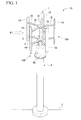
- Fig. 1 is an appearance view showing a vertical axis wind power generator 10 according to a first embodiment.
- Fig. 2 is a side cross-sectional view showing the vertical axis wind power generator 10.
- the vertical axis wind power generator (the vertical axis fluid power generator) 10 has a rotary mechanism 10A configured to be rotated by receiving wind (a working fluid) W, and a power generation mechanism 10B configured to convert mechanical energy obtained by the rotary mechanism 10A into electrical energy.
- the rotary mechanism 10A includes a windmill 1 configured to receive the wind W, a rotary axis (an axis body) 2 connected to the windmill 1, and a casing (a support body) 4 configured to rotatably support the rotary axis 2 around a central axis C via a bearing 3.
- the power generation mechanism 10B includes a power generator 5 configured to convert mechanical energy obtained as the rotary axis 2 rotates in a circumferential direction (around the central axis C) into electrical energy to generate electric power.
- the rotary mechanism 10A and the power generation mechanism 10B are disposed on a tower (a post) 6 standing on the ground F and extending in the vertical direction.
- the windmill 1 is a so-called gyro mill type windmill.
- the windmill 1 has a plurality of blades 1A formed in a rectangular plate shape or a strip shape and extending in the vertical direction.
- the plurality of blades 1A are disposed around the central axis C of the rotary axis 2 at equal intervals in the circumferential direction.
- the plurality of blades 1A are connected to the rotary axis 2 via a plurality of arms 1B configured to support the plurality of blades 1A.
- the blade 1A is formed in a shape to generate lift force when the blade 1A receives the wind W.
- the windmill 1 is rotated around the central axis C of the rotary axis 2 by the lift force.
- the windmill 1 has independent on a wind direction.
- the windmill 1 is set to be rotatable around the central axis C of the rotary axis 2 with respect to the wind W in all directions.
- the rotary axis 2 to which the windmill 1 (the blade 1A) is connected extends in the vertical direction such that the central axis C is perpendicular to the ground F.
- the rotary axis 2 is rotatably axially supported with respect to the casing 4 via the bearing 3.
- a first end of the arm 1B having a rectangular shape or a strip shape is connected to an outer circumferential surface of the rotary axis 2.
- the arms 1B protrude outward in the radial direction.
- the arms 1B are disposed in the circumferential direction of the rotary axis 2 at equal intervals.
- the blade 1A is connected to a second end of the arm 1B.
- the pair of arms 1B are installed at one blade 1A in parallel in the central axis C direction.
- the rotary axis 2 is rotatably supported with respect to the casing 4 as the bearings 3 are installed in the vicinity of a central section and a lower end section thereof.
- the bearings 3 are constituted by a radial bearing 13 which are spaced apart from each other in the central axis C direction of the rotary axis 2 and a double row of angular bearings 14Aand 14B.
- the radial bearing 13 is disposed at an end section near the power generator 5 of the central axis C direction in the rotary axis 2.
- An inner rim 15 of the radial bearing 13 is fixed to a lower end side of the rotary axis 2.
- the double row of angular bearings 14A and 14B are disposed at a side near the windmill 1 of the central axis C direction in the rotary axis 2.
- Inner rims 17 and 17 of the double row of angular bearings 14A and 14B are fixedly installed at a central section of the rotary axis 2.
- the casing 4 is formed in a multi-stage tubular shape in which an upper portion 4A near the windmill 1 (a first end side) has a diameter smaller than that of a lower portion 4B near a tower 6 (a second end side) opposite to the windmill 1. A lower end section of the lower portion 4B of the casing 4 is connected to an upper end section of the tower 6.
- Outer rims 18 of the angular bearings 14A and 14B are fixed to an upper end side of an inner circumferential surface of the upper portion 4A of the casing 4.
- An outer rim 16 of the radial bearing 13 is fixed to a lower end side of an inner circumferential surface of the upper portion 4A of the casing 4.
- the radial bearing 13 and the angular bearings 14A and 14B of the bearings 3 have a plurality of balls 7 having the same diameter.
- the radial bearing 13 and the angular bearings 14A and 14B may be set to be opposite to those described above.
- the radial bearing 13 may be disposed at a side near the windmill 1 of the rotary axis 2
- the angular bearings 14A and 14B may be disposed at a side near the power generator 5 of the rotary axis 2.
- the angular bearings 14A and 14B may be disposed in front alignment or parallel alignment rather than rear alignment.
- the power generator 5, a controller (not shown), and so on, are accommodated in the lower portion 4B of the casing 4.
- the power generator 5 is configured to convert a rotational force (mechanical energy) obtained by rotation of the rotary axis 2 into electrical energy to generate electric power.
- the power generator 5 includes a magnet rotor 8 connected to a lower end of the rotary axis 2 and rotated with the rotary axis 2, and a coil stator 9 disposed to surround an outer circumferential side of the magnet rotor 8.
- the magnet rotor 8 connected to the rotary axis 2 is also rotated around the central axis C.
- the magnet rotor 8 rotates concentrically with the windmill 1 and the rotary axis 2 (around the central axis C).
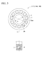
- Fig. 3 is a view showing the bearing 3 according to the first embodiment.
- the rotary axis 2 of the vertical axis wind turbine generator 10 may be efficiently and easily rotated.
- the bearing 3 used for the rotary axis 2 needs to axially support the rotary axis 2 to rotate even when the windmill 1 receives the wind W having a low wind speed. For this reason, the bearings 3 (the radial bearing 13 and the angular bearings 14A and 14B) require that starting torque and rotational torque be extremely low.
- the bearing 3 configured to axially support the rotary axis 2 should have performance such that a sufficient static load capacity (basic static load rating) and dynamic load capacity (basic dynamic load rating) are satisfied, because the bearing 3 receives an external force having large variation (the wind W received by the windmill 1) for a long time.
- the bearing 3 should have a low rotational torque while having a sufficient load rating.
- a diameter d1 of the rotary axis 2 is substantially consequently determined (a necessary minimum diameter or more) from conditions (working conditions) such as maximum wind power or the like received by the windmill 1.
- An inner diameter d of the bearing 3 is approximately consequently determined, because the inner diameter d is the same as the diameter d1 of the rotary axis 2.
- the ball center diameter Dpw is derived by determining (1) the ball diameter Dw.
- the bearing 3 in order to cause the bearing 3 to have a sufficient load capacity and a low rotational torque, the bearing 3 should satisfy the following conditions.
- performance required for the bearing 3 configured to axially support the rotary axis 2 is obtained from a specification (working conditions) of the windmill 1.
- Load ratings (a basic dynamic load rating and a basic static load rating) and starting torque required for the bearing 3 are obtained.
- a relation curve that can satisfy the obtained required performance (the basic dynamic load rating, the basic static load rating and the starting torque) is obtained. That is, a relation (a relation curve) between (1) the ball diameter Dw and (2) the rolling contact groove curvature ⁇ of the bearing is obtained.
- Fig. 4 is a graph showing the relation curve between the ball ratio ⁇ and the rolling contact groove curvature ⁇ in order to cause the bearing 3 to satisfy the required performance.
- Fig. 4 shows the case in which a wind receiving area of the windmill 1 is 9 m 2 .
- the wind condition is IEC61400-2 class IV.
- a windmill having a wind receiving area of 2 m 2 to less than 200 m 2 is referred to as a small windmill.
- a vertical axis represents a ball ratio ⁇
- a horizontal axis represents a rolling contact groove curvature ⁇ of the bearing.
- the vertical axis shows a ratio (the ball ratio ⁇ ) of the ball diameter Dw with respect to the diameter d1 of the rotary axis 2, not the ball diameter Dw itself represented by (1) above. Since the diameter d1 of the rotary axis 2 should not be limited to be designed to a necessary minimum dimension, the ball ratio ⁇ is used.
- the ball ratio ⁇ Dw / d the ball diameter Dw the rotary axis diameter d
- the bearing 3 should satisfy the load rating and the starting torque.
- the bearing 3 should satisfy at least one of the basic dynamic load rating and the basic static load rating, and further satisfy the starting torque. More preferably, the bearing 3 is desired to satisfy all of the basic dynamic load rating, the basic static load rating and the starting torque.
- the bearing 3 is appropriate as a bearing used for the rotary axis 2 of the vertical axis wind power generator 10.
- the ball diameter Dw and (2) the rolling contact groove curvature ⁇ be plotted in the region I.
- the ball diameter Dw is about 20% or less.
- the ball diameter Dw is 10% to 15%.
- the rolling contact groove curvature ⁇ is 54% to 100%.
- the rolling contact groove curvature ⁇ is 55% to 65%.
- the ball having an excessively small or large diameter (in particular, a diameter of 1 inch or more) has low marketability and increases cost. For this reason, the ball diameter Dw of 20% or less is appropriate.
- the ball diameter Dw is less than 10%, it is difficult to satisfy both of the load rating and the starting torque. For this reason, the ball diameter Dw of 10% or more is appropriate.
- the rolling contact groove curvature ⁇ of the bearing is less than 54%, similar to the case in which the ball diameter Dw is 10% or less, it is difficult to satisfy both of the load rating and the starting torque. For this reason, the rolling contact groove curvature ⁇ of the bearing of 54% or more is appropriate.
- the rolling contact groove curvature ⁇ of the bearing exceeds 100%, similar to the case in which the ball diameter Dw exceeds 20%, it is difficult to satisfy both of the load rating and the starting torque. For this reason, the rolling contact groove curvature ⁇ of the bearing of 100% or less is appropriate.
- the bearing 3 has a sufficient load rating and a small rotational torque, because (1) the ball diameter Dw is small and (2) the rolling contact groove curvature ⁇ of the bearing is large. Therefore, even when the windmill 1 receives the wind W having a very low wind speed, the rotary axis 2 can be rotated.
- the windmill 1 can receive an external force (the wind W received by the windmill 1) having a large variation for a long time. Accordingly, the vertical axis wind power generator 10 can generate power with high efficiency.
- Fig. 5 is a side cross-sectional view showing a vertical axis wind power generator 20 and a bearing 23 according to a second embodiment.
- the second embodiment will be described focusing on differences from the vertical axis wind power generator 10 and the bearing 3 according to the first embodiment, and description of the same members or the like as the vertical axis wind power generator 10 and the bearing 3 will be omitted.
- a rotary axis 22 of the vertical axis wind power generator 20 is axially supported by the bearing 23.
- the bearing 23 includes the above-mentioned radial bearing 13 and angular bearings 24A and 24B.
- a rolling contact groove 33 in which the plurality of balls 7 roll in contact therewith are formed at a portion in which the double row of angular bearings 24A and 24B are installed.
- the angular bearings 24A and 24B have only outer rims 28 and have no inner rim. For this reason, a rolling contact groove 33 in which the balls 7 roll in contact therewith is formed at an outer circumferential surface of the rotary axis 22.
- the rolling contact groove 33 is formed in an annular shape extending in a circumferential direction in an outer circumferential surface of the rotary axis 22.
- the rolling contact groove 33 is formed in a semi-circular shape recessed toward the central axis C.
- Vertical positions of the radial bearing 13 and the angular bearings 24A and 24B may be set to be opposite to the above-mentioned type.
- the radial bearing 13 may be disposed at a side near the windmill 1 of the rotary axis 2 and the angular bearings 24A and 24B may be disposed at a side near the power generator 5 of the rotary axis 2.
- the angular bearings 24A and 24B may be disposed in front alignment or parallel alignment rather than rear alignment.
- the bearings should be individually designed (employed).
- the inner diameter d of the angular bearings 24A and 24B is not the diameter d1 of the rotary axis 22 but becomes a diameter d2 of a portion thereof in which the rolling contact groove 33 is formed.
- the bearing 23 has a sufficient load rating and a small rotational torque, because (1) the ball diameter Dw is reduced and (2) the rolling contact groove curvature ⁇ is increased. Therefore, even when the windmill 1 receives the wind W having a very small wind speed, the rotary axis 22 can be rotated. In addition, the windmill 1 can receive an external force (the wind W received by the windmill 1) having a large variation for a long time. Accordingly, the vertical axis wind turbine generator 20 can generate power with high efficiency.
- the radial bearing may have no inner rim, and a rolling contact groove may be formed in the rotary axis 22.
- the radial bearing and the angular bearing may have only the inner rim and have no outer rim, and a rolling contact groove may be formed at an inner circumferential surface of the casing 4 (the upper portion 4A).
- the rotary axis 2 or 22 is not limited to an integrated structure but a plurality of axis members may be connected;
- the pair of arms 1B may be spaced apart from each other in the central axis C direction and may not be parallel.
- the ball diameters of the radial bearing 13 of the bearings 3 and 23 and the angular bearings 14A, 14B, 24A and 24B may have the same diameter or different diameters.
Landscapes
- Engineering & Computer Science (AREA)
- General Engineering & Computer Science (AREA)
- Mechanical Engineering (AREA)
- Life Sciences & Earth Sciences (AREA)
- Sustainable Development (AREA)
- Sustainable Energy (AREA)
- Chemical & Material Sciences (AREA)
- Combustion & Propulsion (AREA)
- Power Engineering (AREA)
- Wind Motors (AREA)
- Rolling Contact Bearings (AREA)
Abstract
Description
- The present invention relates to a bearing for a vertical axis windmill and a vertical axis wind power generator.
- Priority is claimed on Japanese Patent Application No.
2011-260317, filed November 29, 2011 - As a vertical axis fluid power generator configured to perform power generation using a flow of a fluid, for example, a wind power generator using a flow of wind (a working fluid) has been developed. Such a vertical axis wind power generator includes a axis body, a plurality of blades (a windmill), a support body, and a power generator.
- The plurality of blades are arranged around a central axis of the axis body at intervals and connected to the axis body. The support body rotatably supports the axis body around the central axis via a bearing. The power generator converts mechanical energy obtained as the axis body rotates in a circumferential direction into electrical energy, generating electric power.
- For example, in a wind power generator disclosed in
Patent Literature 1, a rotary mechanism (an axis body) to which vertical wings (blades) are connected extends in a direction perpendicular to the ground (a direction perpendicular to a horizontal plane). The rotary mechanism is rotatably supported with respect to an intermediate fixed axis (a support body) via a pair of bearings (ball bearings). - [Patent Literature 1] Japanese Unexamined Patent Application, First Publication No.
2006-207374 - However, in a vertical wind power generator of the related art, there are problems as described below. The axis body is set to a diameter needed for securing strength. Then, a commercially available ball bearing such as 70XX or the like (JIS B 1512) is selected to correspond to the diameter of the axis body. However, in the ball bearing selected as described above, a load rating is excessively increased (over engineered). In addition, since a load capacity (a dynamic load rating or a static load rating) of the ball bearing is also large, a torque resistance is also increased. For this reason, power generation efficiency may be decreased by interference with rotation of the axis body (in particular, rotation in a low wind speed area), and efficiency of the windmill may be degraded.
- The present invention provides a bearing for vertical axis windmill and a vertical axis wind power generator that are capable of reducing torque resistance, smoothly rotating an axis body, and increasing power generation efficiency.
- According to a first aspect of the present invention, a bearing for vertical axis windmill configured to rotatably support a vertical axis of a vertical axis windmill, and the bearing includes a ball, a diameter of the ball and a curvature of a rolling groove of the ball are set to satisfy a predetermined starting torque and a load rating.
- According to a second aspect of the present invention, in the bearing for vertical axis windmill according to the first aspect, the curvature of the rolling groove is 54% or more and 100% or less.
- According to a third aspect of the present invention, in the bearing for vertical axis windmill according to the first or second aspect, the diameter of the ball has a ratio of 20% or less with respect to the vertical axis.
- According to a fourth aspect of the present invention, in the bearing for vertical axis windmill according to any one of the first to third aspects, the rolling groove of the ball is formed in an outer circumferential surface of the vertical axis.
- According to a fifth aspect of the present invention, a vertical axis wind power generator includes: a windmill configured to rotate around a central axis extending in a vertical direction; an axis body configured to be disposed along the central axis and to be connected with the windmill; a support body configured to rotatably support the axis body around the central axis via a bearing; and a power generator configured to generate electric power by rotation of the axis body, and the bearing is the bearing according to any one of the first to four aspects.
- According to the present invention, the bearing for a vertical axis windmill and the vertical axis wind power generator that are capable of reducing torque resistance, smoothly rotating the axis body and increasing power generation efficiency can be realized.
-
-
Fig. 1 is an appearance view showing a vertical axis wind turbine generator according to a first embodiment of the present invention. -
Fig. 2 is a side cross-sectional view showing the vertical axis wind power generator according to the first embodiment of the present invention. -
Fig. 3 is a view showing a bearing according to the first embodiment of the present invention. -
Fig. 4 is a graph showing a relation curve between a curvature of a rolling groove and a ball ratio satisfying required performance of the bearing. -
Fig. 5 is a side cross-sectional view showing a vertical axis wind power generator and a bearing according to a second embodiment of the present invention. -
Fig. 1 is an appearance view showing a vertical axiswind power generator 10 according to a first embodiment.Fig. 2 is a side cross-sectional view showing the vertical axiswind power generator 10. - As shown in
Figs. 1 and2 , the vertical axis wind power generator (the vertical axis fluid power generator) 10 has arotary mechanism 10A configured to be rotated by receiving wind (a working fluid) W, and apower generation mechanism 10B configured to convert mechanical energy obtained by therotary mechanism 10A into electrical energy. - The
rotary mechanism 10A includes awindmill 1 configured to receive the wind W, a rotary axis (an axis body) 2 connected to thewindmill 1, and a casing (a support body) 4 configured to rotatably support therotary axis 2 around a central axis C via abearing 3. - The
power generation mechanism 10B includes apower generator 5 configured to convert mechanical energy obtained as therotary axis 2 rotates in a circumferential direction (around the central axis C) into electrical energy to generate electric power. - The
rotary mechanism 10A and thepower generation mechanism 10B are disposed on a tower (a post) 6 standing on the ground F and extending in the vertical direction. - The
windmill 1 is a so-called gyro mill type windmill. Thewindmill 1 has a plurality ofblades 1A formed in a rectangular plate shape or a strip shape and extending in the vertical direction. The plurality ofblades 1A are disposed around the central axis C of therotary axis 2 at equal intervals in the circumferential direction. The plurality ofblades 1A are connected to therotary axis 2 via a plurality ofarms 1B configured to support the plurality ofblades 1A. - The
blade 1A is formed in a shape to generate lift force when theblade 1A receives the wind W. Thewindmill 1 is rotated around the central axis C of therotary axis 2 by the lift force. - The
windmill 1 has independent on a wind direction. Thewindmill 1 is set to be rotatable around the central axis C of therotary axis 2 with respect to the wind W in all directions. - As shown in
Fig. 2 , therotary axis 2 to which the windmill 1 (theblade 1A) is connected extends in the vertical direction such that the central axis C is perpendicular to the ground F. Therotary axis 2 is rotatably axially supported with respect to thecasing 4 via thebearing 3. - A first end of the
arm 1B having a rectangular shape or a strip shape is connected to an outer circumferential surface of therotary axis 2. Thearms 1B protrude outward in the radial direction. Thearms 1B are disposed in the circumferential direction of therotary axis 2 at equal intervals. Then, theblade 1A is connected to a second end of thearm 1B. The pair ofarms 1B are installed at oneblade 1A in parallel in the central axis C direction. - The
rotary axis 2 is rotatably supported with respect to thecasing 4 as thebearings 3 are installed in the vicinity of a central section and a lower end section thereof. Thebearings 3 are constituted by aradial bearing 13 which are spaced apart from each other in the central axis C direction of therotary axis 2 and a double row ofangular bearings 14Aand 14B. - The
radial bearing 13 is disposed at an end section near thepower generator 5 of the central axis C direction in therotary axis 2. Aninner rim 15 of theradial bearing 13 is fixed to a lower end side of therotary axis 2. - The double row of
angular bearings windmill 1 of the central axis C direction in therotary axis 2.Inner rims angular bearings rotary axis 2. - The
casing 4 is formed in a multi-stage tubular shape in which anupper portion 4A near the windmill 1 (a first end side) has a diameter smaller than that of alower portion 4B near a tower 6 (a second end side) opposite to thewindmill 1. A lower end section of thelower portion 4B of thecasing 4 is connected to an upper end section of thetower 6. -
Outer rims 18 of theangular bearings upper portion 4A of thecasing 4. Anouter rim 16 of theradial bearing 13 is fixed to a lower end side of an inner circumferential surface of theupper portion 4A of thecasing 4. - The
radial bearing 13 and theangular bearings bearings 3 have a plurality ofballs 7 having the same diameter. - Vertical positions of the
radial bearing 13 and theangular bearings radial bearing 13 may be disposed at a side near thewindmill 1 of therotary axis 2, and theangular bearings power generator 5 of therotary axis 2. - The
angular bearings - The
power generator 5, a controller (not shown), and so on, are accommodated in thelower portion 4B of thecasing 4. - The
power generator 5 is configured to convert a rotational force (mechanical energy) obtained by rotation of therotary axis 2 into electrical energy to generate electric power. Thepower generator 5 includes amagnet rotor 8 connected to a lower end of therotary axis 2 and rotated with therotary axis 2, and acoil stator 9 disposed to surround an outer circumferential side of themagnet rotor 8. - When the
windmill 1 receives the wind W to rotate therotary axis 2 around the central axis C, themagnet rotor 8 connected to therotary axis 2 is also rotated around the central axis C. Themagnet rotor 8 rotates concentrically with thewindmill 1 and the rotary axis 2 (around the central axis C). - As the
magnet rotor 8 rotates around the central axis C with respect to thecoil stator 9, electromagnetic induction is generated between themagnet rotor 8 and thecoil stator 9, and then electric power is generated. - Required performance of the
bearing 3 configured to axially support therotary axis 2 will be described in detail. -
Fig. 3 is a view showing thebearing 3 according to the first embodiment. - The
rotary axis 2 of the vertical axiswind turbine generator 10 may be efficiently and easily rotated. Thebearing 3 used for therotary axis 2 needs to axially support therotary axis 2 to rotate even when thewindmill 1 receives the wind W having a low wind speed. For this reason, the bearings 3 (theradial bearing 13 and theangular bearings - Meanwhile, the
bearing 3 configured to axially support therotary axis 2 should have performance such that a sufficient static load capacity (basic static load rating) and dynamic load capacity (basic dynamic load rating) are satisfied, because thebearing 3 receives an external force having large variation (the wind W received by the windmill 1) for a long time. - Therefore, the
bearing 3 should have a low rotational torque while having a sufficient load rating. - In a specification (performance) of the
bearing 3, the following four parameters are known as shape parameters for determining rotational torque and load ratings (a basic static load rating and a basic dynamic load rating). - (1) A ball diameter Dw
- (2) A rolling contact groove curvature α (α = R/Dw, rolling contact groove radius R)
- (3) A ball center diameter Dpw
- (4) The number of balls z
- In general, when numerical values of(1), (3) and (4) are increased, the rotational torque and the load ratings are also increased. Meanwhile, it is known that, when a numerical value of (2) is increased, the rotational torque and the load ratings are decreased.
- For this reason, balance of these four parameters is important.
- A diameter d1 of the
rotary axis 2 is substantially consequently determined (a necessary minimum diameter or more) from conditions (working conditions) such as maximum wind power or the like received by thewindmill 1. An inner diameter d of thebearing 3 is approximately consequently determined, because the inner diameter d is the same as the diameter d1 of therotary axis 2. - When the inner diameter d of the
bearing 3 is determined, (3) the ball center diameter Dpw is derived by determining (1) the ball diameter Dw. - (4) The number of balls z is derived by determining (1) the ball diameter Dw and (3) the ball center diameter Dpw. This is because a maximum number of balls B that can be disposed on a trajectory is physically determined. When the number of balls z is reduced, since a load per ball B is increased and reliability decreased, reduction in the number of balls is not practical.
- As a result, it will be understood that, when an
optimal bearing 3 is to be designed (employed) in therotary axis 2 of thewindmill 1, two parameters of (1) the ball diameter Dw and (2) the rolling contact groove curvature α of the bearing become important parameters. - Accordingly, in order to cause the
bearing 3 to have a sufficient load capacity and a low rotational torque, thebearing 3 should satisfy the following conditions. - (Condition 1) The ball diameter Dw is reduced.
- (Condition 2) The rolling contact groove curvature α of the bearing is increased.
- Design (employment) of the
bearing 3 that satisfies the above-mentioned conditions is performed in the following sequence. - First, performance required for the
bearing 3 configured to axially support therotary axis 2 is obtained from a specification (working conditions) of thewindmill 1. Load ratings (a basic dynamic load rating and a basic static load rating) and starting torque required for thebearing 3 are obtained. - Next, a relation curve that can satisfy the obtained required performance (the basic dynamic load rating, the basic static load rating and the starting torque) is obtained. That is, a relation (a relation curve) between (1) the ball diameter Dw and (2) the rolling contact groove curvature α of the bearing is obtained.
-
Fig. 4 is a graph showing the relation curve between the ball ratio β and the rolling contact groove curvature α in order to cause thebearing 3 to satisfy the required performance.Fig. 4 shows the case in which a wind receiving area of thewindmill 1 is 9 m2. The wind condition is IEC61400-2 class IV. - In IEC61400-2, a windmill having a wind receiving area of 2 m2 to less than 200 m2 is referred to as a small windmill.
- In
Fig. 4 , a vertical axis represents a ball ratio β, and a horizontal axis represents a rolling contact groove curvature α of the bearing. The vertical axis shows a ratio (the ball ratio β) of the ball diameter Dw with respect to the diameter d1 of therotary axis 2, not the ball diameter Dw itself represented by (1) above. Since the diameter d1 of therotary axis 2 should not be limited to be designed to a necessary minimum dimension, the ball ratio β is used.
- As described above, the
bearing 3 should satisfy the load rating and the starting torque. Thebearing 3 should satisfy at least one of the basic dynamic load rating and the basic static load rating, and further satisfy the starting torque. More preferably, thebearing 3 is desired to satisfy all of the basic dynamic load rating, the basic static load rating and the starting torque. - In the case shown in
Fig. 4 , it can be understood that, as long as (1) the ball diameter Dw and (2) the rolling contact groove curvature α of the bearing are plotted in a region I, a region II and a region III, thebearing 3 is appropriate as a bearing used for therotary axis 2 of the vertical axiswind power generator 10. - Further, in the
bearing 3, it is appropriate that (1) the ball diameter Dw and (2) the rolling contact groove curvature α be plotted in the region I. (1) The ball diameter Dw is about 20% or less. Preferably, (1) the ball diameter Dw is 10% to 15%. (2) The rolling contact groove curvature α is 54% to 100%. Preferably, (2) the rolling contact groove curvature α is 55% to 65%. - For example, a bearing having a rolling contact groove curvature α = 60% and a ball ratio β=12% may be designed (employed) as the
bearing 3. - When the ball diameter Dw exceeds 20%, it is difficult to satisfy both of the load rating and the starting torque. When the ball diameter Dw is excessively larger than the diameter of the
rotary axis 2, the number ofballs 7 to be disposed in thebearing 3 is reduced, and a load applied to each of theballs 7 becomes excessive, which is not practical. - In general, the ball having an excessively small or large diameter (in particular, a diameter of 1 inch or more) has low marketability and increases cost. For this reason, the ball diameter Dw of 20% or less is appropriate.
- When the ball diameter Dw is less than 10%, it is difficult to satisfy both of the load rating and the starting torque. For this reason, the ball diameter Dw of 10% or more is appropriate.
- When the rolling contact groove curvature α of the bearing is less than 54%, similar to the case in which the ball diameter Dw is 10% or less, it is difficult to satisfy both of the load rating and the starting torque. For this reason, the rolling contact groove curvature α of the bearing of 54% or more is appropriate.
- When the rolling contact groove curvature α of the bearing exceeds 100%, similar to the case in which the ball diameter Dw exceeds 20%, it is difficult to satisfy both of the load rating and the starting torque. For this reason, the rolling contact groove curvature α of the bearing of 100% or less is appropriate.
- As described above, in the vertical axis
wind power generator 10 according to the first embodiment, thebearing 3 has a sufficient load rating and a small rotational torque, because (1) the ball diameter Dw is small and (2) the rolling contact groove curvature α of the bearing is large. Therefore, even when thewindmill 1 receives the wind W having a very low wind speed, therotary axis 2 can be rotated. - In addition, the
windmill 1 can receive an external force (the wind W received by the windmill 1) having a large variation for a long time. Accordingly, the vertical axiswind power generator 10 can generate power with high efficiency. -
Fig. 5 is a side cross-sectional view showing a vertical axiswind power generator 20 and abearing 23 according to a second embodiment. - The second embodiment will be described focusing on differences from the vertical axis
wind power generator 10 and thebearing 3 according to the first embodiment, and description of the same members or the like as the vertical axiswind power generator 10 and thebearing 3 will be omitted. - A
rotary axis 22 of the vertical axiswind power generator 20 is axially supported by thebearing 23. Thebearing 23 includes the above-mentionedradial bearing 13 andangular bearings - In the
rotary axis 22 to which thewindmill 1 is connected, a rollingcontact groove 33 in which the plurality ofballs 7 roll in contact therewith are formed at a portion in which the double row ofangular bearings angular bearings outer rims 28 and have no inner rim. For this reason, a rollingcontact groove 33 in which theballs 7 roll in contact therewith is formed at an outer circumferential surface of therotary axis 22. - The rolling
contact groove 33 is formed in an annular shape extending in a circumferential direction in an outer circumferential surface of therotary axis 22. The rollingcontact groove 33 is formed in a semi-circular shape recessed toward the central axis C. - Vertical positions of the
radial bearing 13 and theangular bearings radial bearing 13 may be disposed at a side near thewindmill 1 of therotary axis 2 and theangular bearings power generator 5 of therotary axis 2. - The
angular bearings - Required performance of the bearing 23 configured to axially support the
rotary axis 22 is the same as that of thebearing 3. Therefore, design (employment) of thebearing 23 that satisfies the above-mentioned condition may be formed in the same sequence as that of thebearing 3. - However, in the
radial bearing 13 and theangular bearings angular bearings rotary axis 22 but becomes a diameter d2 of a portion thereof in which the rollingcontact groove 33 is formed. - Even in the vertical axis
wind power generator 20 according to the second embodiment, thebearing 23 has a sufficient load rating and a small rotational torque, because (1) the ball diameter Dw is reduced and (2) the rolling contact groove curvature α is increased. Therefore, even when thewindmill 1 receives the wind W having a very small wind speed, therotary axis 22 can be rotated. In addition, thewindmill 1 can receive an external force (the wind W received by the windmill 1) having a large variation for a long time. Accordingly, the vertical axiswind turbine generator 20 can generate power with high efficiency. - The shapes or combinations shown in the above-mentioned embodiment are merely exemplary, and various modifications may be made based on design requirements without departing from the scope of the present invention.
- The radial bearing may have no inner rim, and a rolling contact groove may be formed in the
rotary axis 22. - The radial bearing and the angular bearing may have only the inner rim and have no outer rim, and a rolling contact groove may be formed at an inner circumferential surface of the casing 4 (the
upper portion 4A). - The
rotary axis - The pair of
arms 1B may be spaced apart from each other in the central axis C direction and may not be parallel. - The ball diameters of the
radial bearing 13 of thebearings angular bearings -
- 1
- windmill
- 2
- rotary axis (axis body)
- 3
- bearing (bearing for vertical axis windmill)
- 4
- casing (support body)
- 5
- power generator
- 7
- ball
- 10
- vertical axis wind power generator
- 13
- radial bearing
- 14A, 14B
- angular bearing
- 20
- vertical axis wind power generator
- 22
- rotary axis (axis body)
- 23
- bearing (bearing for vertical axis windmill)
- 24A, 24B
- angular bearing
- 33
- rolling contact groove
- C
- central axis
Claims (5)
- A bearing for vertical axis windmill configured to rotatably support a vertical axis of a vertical axis windmill, the bearing comprising:a ball,wherein a diameter of the ball and a curvature of a rolling groove of the bearing are set to satisfy a predetermined starting torque and a load rating.
- The bearing for vertical axis windmill according to claim 1, wherein the curvature of the rolling groove is 54% or more and 100% or less.
- The bearing for vertical axis windmill according to claim 1 or 2, wherein the diameter of the ball has a ratio of 20% or less with respect to the vertical axis.
- The bearing for vertical axis windmill according to any one of claims 1 to 3, wherein the rolling groove of the ball is formed in an outer circumferential surface of the vertical axis.
- A vertical axis wind power generator comprising:a windmill configured to rotate around a central shaft extending in a vertical direction;an axis body configured to be disposed along the central aixs and to be connected with the windmill;a support body configured to rotatably support the axis body around the central axis via a bearing for vertical axis windmill; anda power generator configured to generate electric power by rotation of the axis body,wherein the bearing for vertical axis windmill is the bearing according to any one of claims 1 to 4.
Applications Claiming Priority (2)
| Application Number | Priority Date | Filing Date | Title |
|---|---|---|---|
| JP2011260317A JP5509183B2 (en) | 2011-11-29 | 2011-11-29 | Vertical axis wind turbine bearing and vertical axis wind power generator |
| PCT/JP2012/080722 WO2013080998A1 (en) | 2011-11-29 | 2012-11-28 | Bearing for vertical axis wind turbine and vertical axis wind power generation device |
Publications (3)
| Publication Number | Publication Date |
|---|---|
| EP2789865A1 true EP2789865A1 (en) | 2014-10-15 |
| EP2789865A4 EP2789865A4 (en) | 2015-11-25 |
| EP2789865B1 EP2789865B1 (en) | 2021-04-14 |
Family
ID=48535449
Family Applications (1)
| Application Number | Title | Priority Date | Filing Date |
|---|---|---|---|
| EP12853037.5A Active EP2789865B1 (en) | 2011-11-29 | 2012-11-28 | Bearing for vertical axis wind turbine and vertical axis wind power generation device |
Country Status (6)
| Country | Link |
|---|---|
| US (1) | US9797447B2 (en) |
| EP (1) | EP2789865B1 (en) |
| JP (1) | JP5509183B2 (en) |
| CN (1) | CN103958910B (en) |
| TW (1) | TWI525250B (en) |
| WO (1) | WO2013080998A1 (en) |
Families Citing this family (12)
| Publication number | Priority date | Publication date | Assignee | Title |
|---|---|---|---|---|
| JP5509183B2 (en) | 2011-11-29 | 2014-06-04 | Thk株式会社 | Vertical axis wind turbine bearing and vertical axis wind power generator |
| JP5719416B2 (en) * | 2013-09-18 | 2015-05-20 | Thk株式会社 | Design method for vertical axis wind turbine bearings |
| FR3011285B1 (en) * | 2013-09-30 | 2018-03-16 | Electricfil Automotive | ROTOR FOR WIND TURBINE IN PARTICULAR VERTICAL AXIS |
| TWI558913B (en) * | 2014-01-23 | 2016-11-21 | 陳泰維 | The vertical axis wind turbine blades spin angular adjustment device synchronization |
| CN106762422A (en) * | 2015-11-20 | 2017-05-31 | 台湾垂直轴风电科技能源股份有限公司 | Vertical axis wind power plant |
| GB2545416B (en) * | 2015-12-12 | 2018-09-19 | Spinetic Energy Ltd | Wind turbine apparatuses |
| JP6447662B2 (en) | 2017-05-09 | 2019-01-09 | ダイキン工業株式会社 | Electric motor system and turbo compressor provided with the same |
| EP3951119B1 (en) | 2019-04-05 | 2025-02-19 | NTN Corporation | Portable facility provided with natural energy power generation unit |
| CN110439759B (en) * | 2019-08-17 | 2020-06-30 | 温州乾含节能科技有限公司 | Tower frame of vertical axis wind turbine |
| CN110671263A (en) * | 2019-10-30 | 2020-01-10 | 方晓峰 | Vertical axis wind turbine |
| WO2023146434A1 (en) * | 2022-01-25 | 2023-08-03 | Игорь Анатольевич ЕФРЕМОВ | Multi-row bearing |
| US12398751B2 (en) * | 2023-06-01 | 2025-08-26 | Aktiebolaget Skf | Optimized ball bearing and method of designing an optimized ball bearing |
Family Cites Families (17)
| Publication number | Priority date | Publication date | Assignee | Title |
|---|---|---|---|---|
| JP3419015B2 (en) * | 1992-02-24 | 2003-06-23 | 日本精工株式会社 | Manufacturing method of rolling bearing device to which preload is applied |
| JP2001059519A (en) | 1992-02-24 | 2001-03-06 | Nsk Ltd | Double row rolling bearing device |
| DE60022833T2 (en) | 1999-07-19 | 2006-03-23 | Nsk Ltd. | ball-bearing |
| JP2004124953A (en) * | 2002-08-02 | 2004-04-22 | Nsk Ltd | Ball bearing |
| JP2004270792A (en) * | 2003-03-07 | 2004-09-30 | Nsk Ltd | Multi-point contact ball bearing |
| JP2004316816A (en) | 2003-04-17 | 2004-11-11 | Nsk Ltd | Ball bearings and spindle devices for machine tools |
| KR101124854B1 (en) | 2003-06-09 | 2012-03-27 | 신포니아 테크놀로지 가부시끼가이샤 | Vertical shaft-type wind power generation device |
| JPWO2005095794A1 (en) | 2004-03-31 | 2008-07-31 | 株式会社アイ・ピー・ビー | Cantilever vertical axis wind turbine |
| JPWO2005111415A1 (en) | 2004-05-13 | 2008-07-31 | 株式会社アイ・ピー・ビー | Vertical axis wind turbine support arm mounting structure and vertical axis wind turbine |
| JP2006207374A (en) * | 2005-01-25 | 2006-08-10 | Ise:Kk | Wind power generation device |
| JP2006214456A (en) * | 2005-02-01 | 2006-08-17 | Nsk Ltd | Rolling bearing |
| US20100183256A1 (en) * | 2006-08-25 | 2010-07-22 | Nsk Ltd. | Angular ball bearing |
| CN101302994B (en) | 2008-07-10 | 2010-07-07 | 深圳市风发科技发展有限公司 | Vertical shaft wind motor |
| CN101435412B (en) * | 2008-12-19 | 2011-08-24 | 严强 | Vertical shaft wind power generator structure |
| JP5404493B2 (en) * | 2010-03-29 | 2014-01-29 | Ntn株式会社 | Rolling bearing |
| JP5197521B2 (en) | 2009-07-29 | 2013-05-15 | 京セラ株式会社 | Input device |
| JP5509183B2 (en) | 2011-11-29 | 2014-06-04 | Thk株式会社 | Vertical axis wind turbine bearing and vertical axis wind power generator |
-
2011
- 2011-11-29 JP JP2011260317A patent/JP5509183B2/en active Active
-
2012
- 2012-11-28 EP EP12853037.5A patent/EP2789865B1/en active Active
- 2012-11-28 US US14/360,848 patent/US9797447B2/en active Active
- 2012-11-28 CN CN201280058026.0A patent/CN103958910B/en active Active
- 2012-11-28 WO PCT/JP2012/080722 patent/WO2013080998A1/en not_active Ceased
- 2012-11-29 TW TW101144834A patent/TWI525250B/en active
Also Published As
| Publication number | Publication date |
|---|---|
| US9797447B2 (en) | 2017-10-24 |
| EP2789865B1 (en) | 2021-04-14 |
| JP2013113379A (en) | 2013-06-10 |
| CN103958910A (en) | 2014-07-30 |
| TW201333329A (en) | 2013-08-16 |
| WO2013080998A1 (en) | 2013-06-06 |
| JP5509183B2 (en) | 2014-06-04 |
| CN103958910B (en) | 2016-12-07 |
| US20140306459A1 (en) | 2014-10-16 |
| EP2789865A4 (en) | 2015-11-25 |
| TWI525250B (en) | 2016-03-11 |
Similar Documents
| Publication | Publication Date | Title |
|---|---|---|
| EP2789865B1 (en) | Bearing for vertical axis wind turbine and vertical axis wind power generation device | |
| US6975045B2 (en) | Wind power generating system | |
| US8008798B2 (en) | Wind turbine drivetrain system | |
| US20140008915A1 (en) | Gearless contra-rotating wind generator | |
| US20110025071A1 (en) | Hybrid type vertical shaft turbine for wind power generating devices | |
| EP2434150B2 (en) | A three row roller bearing, in particular for a wind turbine | |
| EP2386757A1 (en) | Fixing structure for generator shaft of wind driven generator of outer rotor coreless type | |
| JP5620941B2 (en) | Rotating shaft device of vertical axis type fluid power generation device and vertical shaft type fluid power generation device | |
| US20160312768A1 (en) | Wind Power Generating Apparatus | |
| US20150322922A1 (en) | Generator with stator supported on rotor | |
| US9831743B2 (en) | Machine with two co-axial rotors | |
| KR20170128315A (en) | Wing cars and natural energy generating devices equipped with them | |
| EP2447523B1 (en) | Wind power generator | |
| US9587624B2 (en) | Wind turbine rotor with improved hub system | |
| JP6130680B2 (en) | Vertical axis fluid power generator | |
| CN204967444U (en) | Electric machine | |
| JP2013257045A (en) | Method for designing vertical-axis wind turbine bearing and vertical-axis wind turbine bearing | |
| CN106469951A (en) | Motor | |
| US10495069B2 (en) | Stabilizing a wind turbine assembly | |
| JP2013227866A (en) | Wind power generation system | |
| CN114207997B (en) | Stator for a generator of a wind turbine | |
| JP2017180232A (en) | Air turbine device | |
| EP2889474A1 (en) | Flange connection for direct driven wind turbine | |
| EP2425133A1 (en) | Wind-power unit having a vertical turbine shaft |
Legal Events
| Date | Code | Title | Description |
|---|---|---|---|
| PUAI | Public reference made under article 153(3) epc to a published international application that has entered the european phase |
Free format text: ORIGINAL CODE: 0009012 |
|
| 17P | Request for examination filed |
Effective date: 20140618 |
|
| AK | Designated contracting states |
Kind code of ref document: A1 Designated state(s): AL AT BE BG CH CY CZ DE DK EE ES FI FR GB GR HR HU IE IS IT LI LT LU LV MC MK MT NL NO PL PT RO RS SE SI SK SM TR |
|
| DAX | Request for extension of the european patent (deleted) | ||
| RA4 | Supplementary search report drawn up and despatched (corrected) |
Effective date: 20151023 |
|
| RIC1 | Information provided on ipc code assigned before grant |
Ipc: F03D 9/00 20060101ALI20151019BHEP Ipc: F16C 33/58 20060101ALI20151019BHEP Ipc: F03D 3/00 20060101ALI20151019BHEP Ipc: F16C 33/32 20060101ALI20151019BHEP Ipc: F16C 19/06 20060101ALN20151019BHEP Ipc: F16C 19/14 20060101AFI20151019BHEP Ipc: F03D 3/06 20060101ALI20151019BHEP Ipc: F03D 11/00 20060101ALI20151019BHEP |
|
| STAA | Information on the status of an ep patent application or granted ep patent |
Free format text: STATUS: EXAMINATION IS IN PROGRESS |
|
| 17Q | First examination report despatched |
Effective date: 20190131 |
|
| REG | Reference to a national code |
Ref country code: DE Ref legal event code: R079 Ref document number: 602012075252 Country of ref document: DE Free format text: PREVIOUS MAIN CLASS: F16C0019140000 Ipc: F16C0033320000 |
|
| GRAP | Despatch of communication of intention to grant a patent |
Free format text: ORIGINAL CODE: EPIDOSNIGR1 |
|
| STAA | Information on the status of an ep patent application or granted ep patent |
Free format text: STATUS: GRANT OF PATENT IS INTENDED |
|
| RIC1 | Information provided on ipc code assigned before grant |
Ipc: F16C 33/58 20060101ALI20201023BHEP Ipc: F16C 33/32 20060101AFI20201023BHEP |
|
| INTG | Intention to grant announced |
Effective date: 20201125 |
|
| RIN1 | Information on inventor provided before grant (corrected) |
Inventor name: SAKUYAMA, TAKASHI Inventor name: AIDA, TOMOYUKI Inventor name: HAYASHI, YUKI Inventor name: IIDA, KATSUYA Inventor name: ASO, TOSHIYUKI |
|
| GRAS | Grant fee paid |
Free format text: ORIGINAL CODE: EPIDOSNIGR3 |
|
| GRAA | (expected) grant |
Free format text: ORIGINAL CODE: 0009210 |
|
| STAA | Information on the status of an ep patent application or granted ep patent |
Free format text: STATUS: THE PATENT HAS BEEN GRANTED |
|
| AK | Designated contracting states |
Kind code of ref document: B1 Designated state(s): AL AT BE BG CH CY CZ DE DK EE ES FI FR GB GR HR HU IE IS IT LI LT LU LV MC MK MT NL NO PL PT RO RS SE SI SK SM TR |
|
| REG | Reference to a national code |
Ref country code: GB Ref legal event code: FG4D |
|
| REG | Reference to a national code |
Ref country code: CH Ref legal event code: EP |
|
| REG | Reference to a national code |
Ref country code: DE Ref legal event code: R096 Ref document number: 602012075252 Country of ref document: DE |
|
| REG | Reference to a national code |
Ref country code: IE Ref legal event code: FG4D |
|
| REG | Reference to a national code |
Ref country code: AT Ref legal event code: REF Ref document number: 1382650 Country of ref document: AT Kind code of ref document: T Effective date: 20210515 |
|
| REG | Reference to a national code |
Ref country code: LT Ref legal event code: MG9D |
|
| REG | Reference to a national code |
Ref country code: AT Ref legal event code: MK05 Ref document number: 1382650 Country of ref document: AT Kind code of ref document: T Effective date: 20210414 |
|
| REG | Reference to a national code |
Ref country code: NL Ref legal event code: MP Effective date: 20210414 |
|
| PG25 | Lapsed in a contracting state [announced via postgrant information from national office to epo] |
Ref country code: NL Free format text: LAPSE BECAUSE OF FAILURE TO SUBMIT A TRANSLATION OF THE DESCRIPTION OR TO PAY THE FEE WITHIN THE PRESCRIBED TIME-LIMIT Effective date: 20210414 Ref country code: LT Free format text: LAPSE BECAUSE OF FAILURE TO SUBMIT A TRANSLATION OF THE DESCRIPTION OR TO PAY THE FEE WITHIN THE PRESCRIBED TIME-LIMIT Effective date: 20210414 Ref country code: FI Free format text: LAPSE BECAUSE OF FAILURE TO SUBMIT A TRANSLATION OF THE DESCRIPTION OR TO PAY THE FEE WITHIN THE PRESCRIBED TIME-LIMIT Effective date: 20210414 Ref country code: HR Free format text: LAPSE BECAUSE OF FAILURE TO SUBMIT A TRANSLATION OF THE DESCRIPTION OR TO PAY THE FEE WITHIN THE PRESCRIBED TIME-LIMIT Effective date: 20210414 Ref country code: BG Free format text: LAPSE BECAUSE OF FAILURE TO SUBMIT A TRANSLATION OF THE DESCRIPTION OR TO PAY THE FEE WITHIN THE PRESCRIBED TIME-LIMIT Effective date: 20210714 Ref country code: AT Free format text: LAPSE BECAUSE OF FAILURE TO SUBMIT A TRANSLATION OF THE DESCRIPTION OR TO PAY THE FEE WITHIN THE PRESCRIBED TIME-LIMIT Effective date: 20210414 |
|
| PG25 | Lapsed in a contracting state [announced via postgrant information from national office to epo] |
Ref country code: IS Free format text: LAPSE BECAUSE OF FAILURE TO SUBMIT A TRANSLATION OF THE DESCRIPTION OR TO PAY THE FEE WITHIN THE PRESCRIBED TIME-LIMIT Effective date: 20210814 Ref country code: GR Free format text: LAPSE BECAUSE OF FAILURE TO SUBMIT A TRANSLATION OF THE DESCRIPTION OR TO PAY THE FEE WITHIN THE PRESCRIBED TIME-LIMIT Effective date: 20210715 Ref country code: LV Free format text: LAPSE BECAUSE OF FAILURE TO SUBMIT A TRANSLATION OF THE DESCRIPTION OR TO PAY THE FEE WITHIN THE PRESCRIBED TIME-LIMIT Effective date: 20210414 Ref country code: SE Free format text: LAPSE BECAUSE OF FAILURE TO SUBMIT A TRANSLATION OF THE DESCRIPTION OR TO PAY THE FEE WITHIN THE PRESCRIBED TIME-LIMIT Effective date: 20210414 Ref country code: RS Free format text: LAPSE BECAUSE OF FAILURE TO SUBMIT A TRANSLATION OF THE DESCRIPTION OR TO PAY THE FEE WITHIN THE PRESCRIBED TIME-LIMIT Effective date: 20210414 Ref country code: PL Free format text: LAPSE BECAUSE OF FAILURE TO SUBMIT A TRANSLATION OF THE DESCRIPTION OR TO PAY THE FEE WITHIN THE PRESCRIBED TIME-LIMIT Effective date: 20210414 Ref country code: NO Free format text: LAPSE BECAUSE OF FAILURE TO SUBMIT A TRANSLATION OF THE DESCRIPTION OR TO PAY THE FEE WITHIN THE PRESCRIBED TIME-LIMIT Effective date: 20210714 Ref country code: PT Free format text: LAPSE BECAUSE OF FAILURE TO SUBMIT A TRANSLATION OF THE DESCRIPTION OR TO PAY THE FEE WITHIN THE PRESCRIBED TIME-LIMIT Effective date: 20210816 Ref country code: ES Free format text: LAPSE BECAUSE OF FAILURE TO SUBMIT A TRANSLATION OF THE DESCRIPTION OR TO PAY THE FEE WITHIN THE PRESCRIBED TIME-LIMIT Effective date: 20210414 |
|
| REG | Reference to a national code |
Ref country code: DE Ref legal event code: R097 Ref document number: 602012075252 Country of ref document: DE |
|
| PG25 | Lapsed in a contracting state [announced via postgrant information from national office to epo] |
Ref country code: CZ Free format text: LAPSE BECAUSE OF FAILURE TO SUBMIT A TRANSLATION OF THE DESCRIPTION OR TO PAY THE FEE WITHIN THE PRESCRIBED TIME-LIMIT Effective date: 20210414 Ref country code: DK Free format text: LAPSE BECAUSE OF FAILURE TO SUBMIT A TRANSLATION OF THE DESCRIPTION OR TO PAY THE FEE WITHIN THE PRESCRIBED TIME-LIMIT Effective date: 20210414 Ref country code: EE Free format text: LAPSE BECAUSE OF FAILURE TO SUBMIT A TRANSLATION OF THE DESCRIPTION OR TO PAY THE FEE WITHIN THE PRESCRIBED TIME-LIMIT Effective date: 20210414 Ref country code: SM Free format text: LAPSE BECAUSE OF FAILURE TO SUBMIT A TRANSLATION OF THE DESCRIPTION OR TO PAY THE FEE WITHIN THE PRESCRIBED TIME-LIMIT Effective date: 20210414 Ref country code: SK Free format text: LAPSE BECAUSE OF FAILURE TO SUBMIT A TRANSLATION OF THE DESCRIPTION OR TO PAY THE FEE WITHIN THE PRESCRIBED TIME-LIMIT Effective date: 20210414 Ref country code: RO Free format text: LAPSE BECAUSE OF FAILURE TO SUBMIT A TRANSLATION OF THE DESCRIPTION OR TO PAY THE FEE WITHIN THE PRESCRIBED TIME-LIMIT Effective date: 20210414 |
|
| PLBE | No opposition filed within time limit |
Free format text: ORIGINAL CODE: 0009261 |
|
| STAA | Information on the status of an ep patent application or granted ep patent |
Free format text: STATUS: NO OPPOSITION FILED WITHIN TIME LIMIT |
|
| 26N | No opposition filed |
Effective date: 20220117 |
|
| PG25 | Lapsed in a contracting state [announced via postgrant information from national office to epo] |
Ref country code: IS Free format text: LAPSE BECAUSE OF FAILURE TO SUBMIT A TRANSLATION OF THE DESCRIPTION OR TO PAY THE FEE WITHIN THE PRESCRIBED TIME-LIMIT Effective date: 20210814 Ref country code: AL Free format text: LAPSE BECAUSE OF FAILURE TO SUBMIT A TRANSLATION OF THE DESCRIPTION OR TO PAY THE FEE WITHIN THE PRESCRIBED TIME-LIMIT Effective date: 20210414 |
|
| PG25 | Lapsed in a contracting state [announced via postgrant information from national office to epo] |
Ref country code: MC Free format text: LAPSE BECAUSE OF FAILURE TO SUBMIT A TRANSLATION OF THE DESCRIPTION OR TO PAY THE FEE WITHIN THE PRESCRIBED TIME-LIMIT Effective date: 20210414 |
|
| REG | Reference to a national code |
Ref country code: CH Ref legal event code: PL |
|
| GBPC | Gb: european patent ceased through non-payment of renewal fee |
Effective date: 20211128 |
|
| PG25 | Lapsed in a contracting state [announced via postgrant information from national office to epo] |
Ref country code: LU Free format text: LAPSE BECAUSE OF NON-PAYMENT OF DUE FEES Effective date: 20211128 Ref country code: IT Free format text: LAPSE BECAUSE OF FAILURE TO SUBMIT A TRANSLATION OF THE DESCRIPTION OR TO PAY THE FEE WITHIN THE PRESCRIBED TIME-LIMIT Effective date: 20210414 Ref country code: BE Free format text: LAPSE BECAUSE OF NON-PAYMENT OF DUE FEES Effective date: 20211130 |
|
| REG | Reference to a national code |
Ref country code: BE Ref legal event code: MM Effective date: 20211130 |
|
| PG25 | Lapsed in a contracting state [announced via postgrant information from national office to epo] |
Ref country code: IE Free format text: LAPSE BECAUSE OF NON-PAYMENT OF DUE FEES Effective date: 20211128 Ref country code: GB Free format text: LAPSE BECAUSE OF NON-PAYMENT OF DUE FEES Effective date: 20211128 |
|
| PG25 | Lapsed in a contracting state [announced via postgrant information from national office to epo] |
Ref country code: FR Free format text: LAPSE BECAUSE OF NON-PAYMENT OF DUE FEES Effective date: 20211130 |
|
| PG25 | Lapsed in a contracting state [announced via postgrant information from national office to epo] |
Ref country code: HU Free format text: LAPSE BECAUSE OF FAILURE TO SUBMIT A TRANSLATION OF THE DESCRIPTION OR TO PAY THE FEE WITHIN THE PRESCRIBED TIME-LIMIT; INVALID AB INITIO Effective date: 20121128 Ref country code: CY Free format text: LAPSE BECAUSE OF FAILURE TO SUBMIT A TRANSLATION OF THE DESCRIPTION OR TO PAY THE FEE WITHIN THE PRESCRIBED TIME-LIMIT Effective date: 20210414 |
|
| PG25 | Lapsed in a contracting state [announced via postgrant information from national office to epo] |
Ref country code: LI Free format text: LAPSE BECAUSE OF NON-PAYMENT OF DUE FEES Effective date: 20220630 Ref country code: CH Free format text: LAPSE BECAUSE OF NON-PAYMENT OF DUE FEES Effective date: 20220630 |
|
| P01 | Opt-out of the competence of the unified patent court (upc) registered |
Effective date: 20230920 |
|
| PG25 | Lapsed in a contracting state [announced via postgrant information from national office to epo] |
Ref country code: MK Free format text: LAPSE BECAUSE OF FAILURE TO SUBMIT A TRANSLATION OF THE DESCRIPTION OR TO PAY THE FEE WITHIN THE PRESCRIBED TIME-LIMIT Effective date: 20210414 |
|
| PG25 | Lapsed in a contracting state [announced via postgrant information from national office to epo] |
Ref country code: TR Free format text: LAPSE BECAUSE OF FAILURE TO SUBMIT A TRANSLATION OF THE DESCRIPTION OR TO PAY THE FEE WITHIN THE PRESCRIBED TIME-LIMIT Effective date: 20210414 |
|
| PG25 | Lapsed in a contracting state [announced via postgrant information from national office to epo] |
Ref country code: MT Free format text: LAPSE BECAUSE OF FAILURE TO SUBMIT A TRANSLATION OF THE DESCRIPTION OR TO PAY THE FEE WITHIN THE PRESCRIBED TIME-LIMIT Effective date: 20210414 |
|
| PGFP | Annual fee paid to national office [announced via postgrant information from national office to epo] |
Ref country code: DE Payment date: 20251119 Year of fee payment: 14 |