EP2789491B1 - Disconnector-type clutch for rear wheel-driving device in four-wheel driving electric vehicle - Google Patents
Disconnector-type clutch for rear wheel-driving device in four-wheel driving electric vehicle Download PDFInfo
- Publication number
- EP2789491B1 EP2789491B1 EP14163679.5A EP14163679A EP2789491B1 EP 2789491 B1 EP2789491 B1 EP 2789491B1 EP 14163679 A EP14163679 A EP 14163679A EP 2789491 B1 EP2789491 B1 EP 2789491B1
- Authority
- EP
- European Patent Office
- Prior art keywords
- wheel driving
- driving shaft
- wheel
- disconnector
- type clutch
- Prior art date
- Legal status (The legal status is an assumption and is not a legal conclusion. Google has not performed a legal analysis and makes no representation as to the accuracy of the status listed.)
- Active
Links
Images

Classifications
-
- F—MECHANICAL ENGINEERING; LIGHTING; HEATING; WEAPONS; BLASTING
- F16—ENGINEERING ELEMENTS AND UNITS; GENERAL MEASURES FOR PRODUCING AND MAINTAINING EFFECTIVE FUNCTIONING OF MACHINES OR INSTALLATIONS; THERMAL INSULATION IN GENERAL
- F16D—COUPLINGS FOR TRANSMITTING ROTATION; CLUTCHES; BRAKES
- F16D48/00—External control of clutches
- F16D48/06—Control by electric or electronic means, e.g. of fluid pressure
-
- F—MECHANICAL ENGINEERING; LIGHTING; HEATING; WEAPONS; BLASTING
- F16—ENGINEERING ELEMENTS AND UNITS; GENERAL MEASURES FOR PRODUCING AND MAINTAINING EFFECTIVE FUNCTIONING OF MACHINES OR INSTALLATIONS; THERMAL INSULATION IN GENERAL
- F16D—COUPLINGS FOR TRANSMITTING ROTATION; CLUTCHES; BRAKES
- F16D23/00—Details of mechanically-actuated clutches not specific for one distinct type
- F16D23/12—Mechanical clutch-actuating mechanisms arranged outside the clutch as such
-
- B—PERFORMING OPERATIONS; TRANSPORTING
- B60—VEHICLES IN GENERAL
- B60K—ARRANGEMENT OR MOUNTING OF PROPULSION UNITS OR OF TRANSMISSIONS IN VEHICLES; ARRANGEMENT OR MOUNTING OF PLURAL DIVERSE PRIME-MOVERS IN VEHICLES; AUXILIARY DRIVES FOR VEHICLES; INSTRUMENTATION OR DASHBOARDS FOR VEHICLES; ARRANGEMENTS IN CONNECTION WITH COOLING, AIR INTAKE, GAS EXHAUST OR FUEL SUPPLY OF PROPULSION UNITS IN VEHICLES
- B60K23/00—Arrangement or mounting of control devices for vehicle transmissions, or parts thereof, not otherwise provided for
- B60K23/08—Arrangement or mounting of control devices for vehicle transmissions, or parts thereof, not otherwise provided for for changing number of driven wheels, for switching from driving one axle to driving two or more axles
-
- F—MECHANICAL ENGINEERING; LIGHTING; HEATING; WEAPONS; BLASTING
- F16—ENGINEERING ELEMENTS AND UNITS; GENERAL MEASURES FOR PRODUCING AND MAINTAINING EFFECTIVE FUNCTIONING OF MACHINES OR INSTALLATIONS; THERMAL INSULATION IN GENERAL
- F16D—COUPLINGS FOR TRANSMITTING ROTATION; CLUTCHES; BRAKES
- F16D11/00—Clutches in which the members have interengaging parts
- F16D11/08—Clutches in which the members have interengaging parts actuated by moving a non-rotating part axially
- F16D11/10—Clutches in which the members have interengaging parts actuated by moving a non-rotating part axially with clutching members movable only axially
-
- F—MECHANICAL ENGINEERING; LIGHTING; HEATING; WEAPONS; BLASTING
- F16—ENGINEERING ELEMENTS AND UNITS; GENERAL MEASURES FOR PRODUCING AND MAINTAINING EFFECTIVE FUNCTIONING OF MACHINES OR INSTALLATIONS; THERMAL INSULATION IN GENERAL
- F16D—COUPLINGS FOR TRANSMITTING ROTATION; CLUTCHES; BRAKES
- F16D28/00—Electrically-actuated clutches
-
- F—MECHANICAL ENGINEERING; LIGHTING; HEATING; WEAPONS; BLASTING
- F16—ENGINEERING ELEMENTS AND UNITS; GENERAL MEASURES FOR PRODUCING AND MAINTAINING EFFECTIVE FUNCTIONING OF MACHINES OR INSTALLATIONS; THERMAL INSULATION IN GENERAL
- F16H—GEARING
- F16H48/00—Differential gearings
- F16H48/06—Differential gearings with gears having orbital motion
- F16H48/08—Differential gearings with gears having orbital motion comprising bevel gears
-
- F—MECHANICAL ENGINEERING; LIGHTING; HEATING; WEAPONS; BLASTING
- F16—ENGINEERING ELEMENTS AND UNITS; GENERAL MEASURES FOR PRODUCING AND MAINTAINING EFFECTIVE FUNCTIONING OF MACHINES OR INSTALLATIONS; THERMAL INSULATION IN GENERAL
- F16H—GEARING
- F16H63/00—Control outputs from the control unit to change-speed- or reversing-gearings for conveying rotary motion or to other devices than the final output mechanism
- F16H63/02—Final output mechanisms therefor; Actuating means for the final output mechanisms
- F16H63/30—Constructional features of the final output mechanisms
-
- B—PERFORMING OPERATIONS; TRANSPORTING
- B60—VEHICLES IN GENERAL
- B60K—ARRANGEMENT OR MOUNTING OF PROPULSION UNITS OR OF TRANSMISSIONS IN VEHICLES; ARRANGEMENT OR MOUNTING OF PLURAL DIVERSE PRIME-MOVERS IN VEHICLES; AUXILIARY DRIVES FOR VEHICLES; INSTRUMENTATION OR DASHBOARDS FOR VEHICLES; ARRANGEMENTS IN CONNECTION WITH COOLING, AIR INTAKE, GAS EXHAUST OR FUEL SUPPLY OF PROPULSION UNITS IN VEHICLES
- B60K1/00—Arrangement or mounting of electrical propulsion units
- B60K2001/001—Arrangement or mounting of electrical propulsion units one motor mounted on a propulsion axle for rotating right and left wheels of this axle
-
- B—PERFORMING OPERATIONS; TRANSPORTING
- B60—VEHICLES IN GENERAL
- B60K—ARRANGEMENT OR MOUNTING OF PROPULSION UNITS OR OF TRANSMISSIONS IN VEHICLES; ARRANGEMENT OR MOUNTING OF PLURAL DIVERSE PRIME-MOVERS IN VEHICLES; AUXILIARY DRIVES FOR VEHICLES; INSTRUMENTATION OR DASHBOARDS FOR VEHICLES; ARRANGEMENTS IN CONNECTION WITH COOLING, AIR INTAKE, GAS EXHAUST OR FUEL SUPPLY OF PROPULSION UNITS IN VEHICLES
- B60K23/00—Arrangement or mounting of control devices for vehicle transmissions, or parts thereof, not otherwise provided for
- B60K23/08—Arrangement or mounting of control devices for vehicle transmissions, or parts thereof, not otherwise provided for for changing number of driven wheels, for switching from driving one axle to driving two or more axles
- B60K2023/085—Arrangement or mounting of control devices for vehicle transmissions, or parts thereof, not otherwise provided for for changing number of driven wheels, for switching from driving one axle to driving two or more axles automatically actuated
- B60K2023/0858—Arrangement or mounting of control devices for vehicle transmissions, or parts thereof, not otherwise provided for for changing number of driven wheels, for switching from driving one axle to driving two or more axles automatically actuated with electric means, e.g. electro-hydraulic means
-
- F—MECHANICAL ENGINEERING; LIGHTING; HEATING; WEAPONS; BLASTING
- F16—ENGINEERING ELEMENTS AND UNITS; GENERAL MEASURES FOR PRODUCING AND MAINTAINING EFFECTIVE FUNCTIONING OF MACHINES OR INSTALLATIONS; THERMAL INSULATION IN GENERAL
- F16D—COUPLINGS FOR TRANSMITTING ROTATION; CLUTCHES; BRAKES
- F16D11/00—Clutches in which the members have interengaging parts
- F16D2011/002—Clutches in which the members have interengaging parts using an external and axially slidable sleeve for coupling the teeth of both coupling components together
-
- F—MECHANICAL ENGINEERING; LIGHTING; HEATING; WEAPONS; BLASTING
- F16—ENGINEERING ELEMENTS AND UNITS; GENERAL MEASURES FOR PRODUCING AND MAINTAINING EFFECTIVE FUNCTIONING OF MACHINES OR INSTALLATIONS; THERMAL INSULATION IN GENERAL
- F16D—COUPLINGS FOR TRANSMITTING ROTATION; CLUTCHES; BRAKES
- F16D23/00—Details of mechanically-actuated clutches not specific for one distinct type
- F16D23/12—Mechanical clutch-actuating mechanisms arranged outside the clutch as such
- F16D2023/123—Clutch actuation by cams, ramps or ball-screw mechanisms
Definitions
- the present invention relates to a disconnector-type clutch for a rear wheel-driving device in a 4-wheel driving electric vehicle. More particularly, the present invention relates to a disconnector-type clutch for a rear wheel-driving device in a 4-wheel driving electric vehicle, which can eliminate a loss in the driving force due to a slip of friction plates disposed in a multiple disc clutch by transmitting power to rear wheels using a disconnector-type clutch, instead of the multiple disc clutch in 4-wheel driving, and can prevent a loss in the energy by preventing a differential from unnecessarily rotating when rear wheels are drawn by a driving force of front wheels in 2-wheel driving in which a rear-wheel driving motor is not driven by installing the disconnector-type clutch at a rear end of the differential.
- Motor vehicles are generally driven in a 2-wheel drive mode and a 4-wheel drive mode.
- the 2-wheel drive mode vehicle is classified into a rear engine rear drive (RR) mode, a front engine front drive (FF) mode, a front engine rear drive (FR) mode, etc., in accordance with the position of the engine and whether the driving shaft is connected to the front wheels or rear wheels.
- RR rear engine rear drive
- FF front engine front drive
- FR front engine rear drive
- the 2-wheel drive mode vehicle may be largely classified into an FF mode vehicle and a FR mode vehicle.
- Both of the FF and FR mode vehicles have the engine and the transmission installed at front sides of the vehicles while having different arrangement structures. That is to say, the FF mode vehicle is generally configured such that the engine and the transmission are laterally installed on the vehicle to transmit power to front wheels through a differential integrally formed with the transmission, and the FR mode vehicle is generally configured such that the engine and the transmission are installed on the vehicle back and forth to transmit power from the transmission to rear wheels through a propeller shaft.
- the 4-wheel drive mode vehicle employs a clutch, a transmission and a differential to appropriately exert a driving force of the engine on all four wheels and are classified into a part time mode for switching the drive mode from a 2-wheel drive mode to a 4-wheel drive mode by driver's manual operation and a full time mode (or a full time 4-wheel drive mode) for maintaining the drive mode all the time in a 4-wheel drive mode.
- a 4-wheel drive vehicle basically travels in a 2-wheel drive mode and can be shifted manually by the driver operator from the 2-wheel drive mode to the 4-wheel drive mode when necessary.
- the FF mode part time 4-wheel drive vehicle is configured to supply power to front wheels in the 2-wheel drive mode and distributes the power to rear wheels in the 4-wheel drive mode.
- the FR mode part time 4-wheel drive vehicle is configured to supply power to rear wheels in the 2-wheel drive mode and distributes the power to front wheels in the 4-wheel drive mode.
- the 4-wheel driving electric vehicle uses motors as a power source.
- a front-wheel driving motor and a rear-wheel driving motor are separately installed.
- the power generated from one of the front-wheel driving motor and the rear-wheel driving motor is used in the 2-wheel drive mode, and both of the power generated from the front-wheel driving motor and the power generated from the rear-wheel driving motor are used in the 4-wheel drive mode.
- FIG. 1 is a cross-sectional view of a conventional rear-wheel driving device for a 4-wheel driving electric vehicle.
- the conventional rear-wheel driving device for a 4-wheel driving electric vehicle includes a rear-wheel driving motor 10 generating rotation power for driving the vehicle, a reducer 20 connected to a rotary shaft of the rear-wheel driving motor 10, a multiple disc clutch 30 connected to the reducer 20, a differential 40 connected to the multiple disc clutch 30, and a rear wheel driving shaft 50 connected to the differential 40 and having left and right ends to mount rear wheels (not shown) thereon.
- the aforementioned conventional rear-wheel driving device for a 4-wheel driving electric vehicle operates in the following manner.
- the reducer 20 transmits the rotation power to the multiple disc clutch 30.
- the multiple disc clutch 30 transmits the rotation power transmitted from the reducer 20 to a case of the differential 40, thereby rotating the rear wheel driving shaft 50 connected to the differential 40.
- the rear wheels (not shown) are mounted on opposite ends of the rear wheel driving shaft 50 to perform a differential function and to transmit the driving force to the rear wheels, thereby driving the vehicle.
- the rear-wheel driving motor 10 does not generate the rotation power, and the multiple disc clutch 30 does not transmit the rotation power to the case of the differential 40, so that the rear wheels are not drawn by the driving force of the front wheels.
- US 2007/034031 A1 discloses a shift mechanism with all the features mentioned in the preamble of claim 1.
- the present invention provides a disconnector-type clutch for a rear wheel-driving device in a 4-wheel driving electric vehicle, which can eliminate a loss in the driving force due to a slip of friction plates disposed in a multiple disc clutch by transmitting power to rear wheels using a disconnector-type clutch, instead of the multiple disc clutch in 4-wheel driving.
- the present invention also provides a disconnector-type clutch for a rear wheel-driving device in a 4-wheel driving electric vehicle, which can prevent a loss in the energy by preventing a differential from unnecessarily rotating when rear wheels are drawn by a driving force of front wheels in 2-wheel driving in which a rear-wheel driving motor is not driven by installing the disconnector-type clutch at a rear end of the differential.
- a disconnector-type clutch for a rear wheel-driving device in a 4-wheel driving electric vehicle, the disconnector-type clutch including an actuator motor generating rotation power; a worm gear connected to the actuator motor; a screw rotating in engagement with the worm gear; a first push case converting a rotary motion of the screw into a linear reciprocating motion; a second push case assembled with the first push case; a first spring installed between the first push case and the second push case; a second spring installed at an exterior side of the second push case to provide a restoration force; a shifting fork connected to the second push case and moving forward and backward; and a sleeve connected to the shifting fork and connecting or disconnecting the first rear-wheel driving shaft and the second rear-wheel driving shaft; the sleeve is installed at an interior side of the shifting fork to be spline-coupled to the first rear-wheel driving shaft and the second rear-wheel driving shaft to connect or disconnect the first rear-wheel driving shaft and the
- the first rear-wheel driving shaft may be installed to penetrate the inside of the rear-wheel driving motor.
- the screw may have a centrally formed gear engaged with the worm gear and a screw thread may be formed in both front and rear directions.
- a nut may be installed at one side of the screw, and first and second sensors for sensing forward and rearward motions of the first push case may be installed using the nut.
- the first push case may have outer and inner circumferential surfaces and a screw thread to be engaged with the screw may be formed on the inner circumferential surface.
- the sleeve may connect the first rear-wheel driving shaft and the second rear-wheel driving shaft to be engaged with each other to transmit the rotation power of the first rear-wheel driving shaft to the second rear-wheel driving shaft.
- the sleeve may move so as to disconnect the first rear-wheel driving shaft and the second rear-wheel driving shaft from each other to prevent the rotation power of the first rear-wheel driving shaft from being transmitted to the second rear-wheel driving shaft.
- a loss in the driving force due to a slip of friction plates disposed in a multiple disc clutch can be eliminated by transmitting power to rear wheels using a disconnector-type clutch, instead of the multiple disc clutch in 4-wheel driving.
- a loss in the energy can be prevented by preventing a differential from unnecessarily rotating when rear wheels are drawn by a driving force of front wheels in 2-wheel driving in which a rear-wheel driving motor is not driven by installing the disconnector-type clutch at a rear end of the differential.
- FIG. 2 is a cross-sectional view of a disconnector-type clutch of a rear-wheel driving device for a 4-wheel driving electric vehicle according to an embodiment of the present invention.
- the rear-wheel driving device having the disconnector-type clutch for a rear wheel-driving device in a 4-wheel driving electric vehicle includes a rear-wheel driving motor 10 generating rotation power for driving the vehicle, a reducer 20 receiving the power from the rear-wheel driving motor 10, a differential 40 connected to the reducer 20, a first rear-wheel driving shaft 300 connected to the differential 40 and having one end to mount a rear wheel (not shown) thereon, a second rear-wheel driving shaft 400 installed to face the first rear-wheel driving shaft 300 on the same line and having one end to mount another rear wheel (not shown) thereon, and a disconnector-type clutch 1000 connecting or disconnecting the first rear-wheel driving shaft 300 and the second rear-wheel driving shaft 400.
- the first rear-wheel driving shaft 300 is installed to penetrate the inside of the rear-wheel driving motor 10.
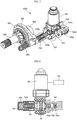
- FIG. 3 is a perspective view of the disconnector-type clutch of a rear-wheel driving device for a 4-wheel driving electric vehicle according to an embodiment of the present invention
- FIG. 4 is a partially cross-sectional view of the disconnector-type clutch of a rear-wheel driving device for a 4-wheel driving electric vehicle according to an embodiment of the present invention.
- the disconnector-type clutch 1000 of a rear-wheel driving device for a 4-wheel driving electric vehicle includes an actuator motor 100 generating rotation power, a worm gear 101 connected to the actuator motor 100, a screw 102 rotating in engagement with the worm gear 101, a first push case 103 a converting a rotary motion of the screw 102 into a linear reciprocating motion, a second push case 103b assembled with the first push case 103a, a first spring 202 installed between the first push case 103a and the second push case 103b, a second spring 203 installed at an exterior side of the second push case 103b to provide a restoration force, a shifting fork 200 connected to the second push case 103b and moving forward and backward, and a sleeve 201 connected to the shifting fork 200 and connecting or disconnecting the first rear-wheel driving shaft 300 and the second rear-wheel driving shaft 400.
- the screw 102 has a centrally formed gear engaged with the worm gear 101 and a screw thread is formed in both front and rear directions.
- a nut 104 is installed at one side of the screw 102, and first and second sensors 105a and 105b for sensing forward and rearward motions of the first push case 103a using the nut 104.
- the first push case 103a has outer and inner circumferential surfaces and a screw thread to be engaged with the screw 102 is formed on the inner circumferential surface.
- a sleeve 201 is installed at an interior side of the shifting fork 200 to be spline-coupled to the first rear-wheel driving shaft 300 and the second rear-wheel driving shaft 400 to connect or disconnect the first rear-wheel driving shaft 300 and the second rear-wheel driving shaft 400.
- the second spring 203 is installed at an exterior side of the second push case 103b to absorb shocks applied from the sleeve 201 and the shifting fork 200 and to provide a elastic force for eliminating the engaged state.
- the aforementioned disconnector-type clutch of a rear-wheel driving device for a 4-wheel driving electric vehicle operates in the following manner.
- the reducer 20 transmits the rotation power to the differential 40, thereby rotating the first rear-wheel driving shaft 300 connected to the differential 40.
- the disconnector-type clutch 1000 connects the first rear-wheel driving shaft 300 and the second rear-wheel driving shaft 400 to each other, thereby transmitting the power from the first rear-wheel driving shaft 300 to the second rear-wheel driving shaft 400.
- the first rear-wheel driving shaft 300 and the second rear-wheel driving shaft 400 Rear wheels (not shown) are mounted on the first rear-wheel driving shaft 300 and the second rear-wheel driving shaft 400 to perform a differential function and to transmit the driving force to the rear wheels, thereby driving the vehicle.
- the disconnector-type clutch 1000 operates in the following manner.
- the worm gear 101 connected to the actuator motor 100 rotates the screw 102 geared therewith in the forward direction.
- the controller 500 senses that the first push case 103a has moved forward.
- the first spring 202 pushes the second push case 103b forward, thereby pushing the shifting fork 200 connected to the second push case 103b forward.
- the shifting fork 200 connected to the second push case 103b and having moved forward pushes the sleeve 201 connected to the second rear-wheel driving shaft 400 to the first rear-wheel driving shaft 300, thereby allowing the sleeve 201 to connect the first rear-wheel driving shaft 300 and the second rear-wheel driving shaft 400 to be engaged with each other, thereby transmitting the rotation power of the first rear-wheel driving shaft 300 to the second rear-wheel driving shaft 400.
- the controller 500 senses that the first push case 103a has moved backward.
- the first spring 202 pushes the second push case 103b backward, thereby pushing the shifting fork 200 connected to the second push case 103b backward.
- the shifting fork 200 connected to the second push case 103b and having moved backward pushes the sleeve 201 connected to the first rear-wheel driving shaft 300 and the second rear-wheel driving shaft 400 to the second rear-wheel driving shaft 400, thereby allowing the sleeve 201 to disconnect the first rear-wheel driving shaft 300 and the second rear-wheel driving shaft 400 to be disengaged from each other, thereby preventing the rotation power of the first rear-wheel driving shaft 300 from being transmitted to the second rear-wheel driving shaft 400.
Landscapes
- Engineering & Computer Science (AREA)
- General Engineering & Computer Science (AREA)
- Mechanical Engineering (AREA)
- Physics & Mathematics (AREA)
- Electromagnetism (AREA)
- Chemical & Material Sciences (AREA)
- Combustion & Propulsion (AREA)
- Transportation (AREA)
- Fluid Mechanics (AREA)
- Arrangement And Driving Of Transmission Devices (AREA)
- Arrangement And Mounting Of Devices That Control Transmission Of Motive Force (AREA)
Description
- The present invention relates to a disconnector-type clutch for a rear wheel-driving device in a 4-wheel driving electric vehicle. More particularly, the present invention relates to a disconnector-type clutch for a rear wheel-driving device in a 4-wheel driving electric vehicle, which can eliminate a loss in the driving force due to a slip of friction plates disposed in a multiple disc clutch by transmitting power to rear wheels using a disconnector-type clutch, instead of the multiple disc clutch in 4-wheel driving, and can prevent a loss in the energy by preventing a differential from unnecessarily rotating when rear wheels are drawn by a driving force of front wheels in 2-wheel driving in which a rear-wheel driving motor is not driven by installing the disconnector-type clutch at a rear end of the differential.
- Motor vehicles are generally driven in a 2-wheel drive mode and a 4-wheel drive mode.
- First, the 2-wheel drive mode vehicle will be described. The 2-wheel drive mode vehicle is classified into a rear engine rear drive (RR) mode, a front engine front drive (FF) mode, a front engine rear drive (FR) mode, etc., in accordance with the position of the engine and whether the driving shaft is connected to the front wheels or rear wheels.
- Since the RR mode is widely used in a sports car, rather than a passenger car or a SUV type vehicle, the 2-wheel drive mode vehicle may be largely classified into an FF mode vehicle and a FR mode vehicle.
- Both of the FF and FR mode vehicles have the engine and the transmission installed at front sides of the vehicles while having different arrangement structures. That is to say, the FF mode vehicle is generally configured such that the engine and the transmission are laterally installed on the vehicle to transmit power to front wheels through a differential integrally formed with the transmission, and the FR mode vehicle is generally configured such that the engine and the transmission are installed on the vehicle back and forth to transmit power from the transmission to rear wheels through a propeller shaft.
- Next, the 4-wheel drive mode vehicle will now be described. The 4-wheel drive mode vehicle employs a clutch, a transmission and a differential to appropriately exert a driving force of the engine on all four wheels and are classified into a part time mode for switching the drive mode from a 2-wheel drive mode to a 4-wheel drive mode by driver's manual operation and a full time mode (or a full time 4-wheel drive mode) for maintaining the drive mode all the time in a 4-wheel drive mode.
- A 4-wheel drive vehicle basically travels in a 2-wheel drive mode and can be shifted manually by the driver operator from the 2-wheel drive mode to the 4-wheel drive mode when necessary. The FF mode part time 4-wheel drive vehicle is configured to supply power to front wheels in the 2-wheel drive mode and distributes the power to rear wheels in the 4-wheel drive mode. The FR mode part time 4-wheel drive vehicle is configured to supply power to rear wheels in the 2-wheel drive mode and distributes the power to front wheels in the 4-wheel drive mode.
- As described above, unlike the 4-wheel driving vehicle using the engine as a power source, the 4-wheel driving electric vehicle uses motors as a power source. In the 4-wheel driving electric vehicle, a front-wheel driving motor and a rear-wheel driving motor are separately installed. The power generated from one of the front-wheel driving motor and the rear-wheel driving motor is used in the 2-wheel drive mode, and both of the power generated from the front-wheel driving motor and the power generated from the rear-wheel driving motor are used in the 4-wheel drive mode.
-
FIG. 1 is a cross-sectional view of a conventional rear-wheel driving device for a 4-wheel driving electric vehicle. - As shown in
FIG. 1 , the conventional rear-wheel driving device for a 4-wheel driving electric vehicle includes a rear-wheel driving motor 10 generating rotation power for driving the vehicle, areducer 20 connected to a rotary shaft of the rear-wheel driving motor 10, amultiple disc clutch 30 connected to thereducer 20, adifferential 40 connected to themultiple disc clutch 30, and a rearwheel driving shaft 50 connected to thedifferential 40 and having left and right ends to mount rear wheels (not shown) thereon. - The aforementioned conventional rear-wheel driving device for a 4-wheel driving electric vehicle operates in the following manner.
- If rotation power is generated from the rear-
wheel driving motor 10 in 4-wheel driving, after receiving the rotation power of the rear-wheel driving motor 10, thereducer 20 transmits the rotation power to themultiple disc clutch 30. - The
multiple disc clutch 30 transmits the rotation power transmitted from thereducer 20 to a case of thedifferential 40, thereby rotating the rearwheel driving shaft 50 connected to thedifferential 40. - The rear wheels (not shown) are mounted on opposite ends of the rear
wheel driving shaft 50 to perform a differential function and to transmit the driving force to the rear wheels, thereby driving the vehicle. - In 2-wheel driving, the rear-
wheel driving motor 10 does not generate the rotation power, and themultiple disc clutch 30 does not transmit the rotation power to the case of thedifferential 40, so that the rear wheels are not drawn by the driving force of the front wheels. - However, in the conventional rear-wheel driving device for a 4-wheel driving electric vehicle, since the power is transmitted using a multiple disc clutch in 4-wheel driving, a loss in the driving force may be generated due to a slip between friction plates disposed within the multiple disc clutch.
- In addition, in the conventional rear-wheel driving device for a 4-wheel driving electric vehicle, in 2-wheel driving in which a rear-wheel driving motor is not driven, a portion of the multiple disc clutch connected to the case of the
differential 40 may unnecessarily rotate together with the differential when the rear wheels are drawn by the driving force of the front wheels, resulting in energy loss. -
US 2007/034031 A1 discloses a shift mechanism with all the features mentioned in the preamble of claim 1. - In order to overcome the above-mentioned shortcomings, the present invention provides a disconnector-type clutch for a rear wheel-driving device in a 4-wheel driving electric vehicle, which can eliminate a loss in the driving force due to a slip of friction plates disposed in a multiple disc clutch by transmitting power to rear wheels using a disconnector-type clutch, instead of the multiple disc clutch in 4-wheel driving.
- In addition, the present invention also provides a disconnector-type clutch for a rear wheel-driving device in a 4-wheel driving electric vehicle, which can prevent a loss in the energy by preventing a differential from unnecessarily rotating when rear wheels are drawn by a driving force of front wheels in 2-wheel driving in which a rear-wheel driving motor is not driven by installing the disconnector-type clutch at a rear end of the differential.
- According to an embodiment of the invention, there is provided a disconnector-type clutch for a rear wheel-driving device in a 4-wheel driving electric vehicle, the disconnector-type clutch including an actuator motor generating rotation power; a worm gear connected to the actuator motor; a screw rotating in engagement with the worm gear; a first push case converting a rotary motion of the screw into a linear reciprocating motion; a second push case assembled with the first push case; a first spring installed between the first push case and the second push case; a second spring installed at an exterior side of the second push case to provide a restoration force; a shifting fork connected to the second push case and moving forward and backward; and a sleeve connected to the shifting fork and connecting or disconnecting the first rear-wheel driving shaft and the second rear-wheel driving shaft; the sleeve is installed at an interior side of the shifting fork to be spline-coupled to the first rear-wheel driving shaft and the second rear-wheel driving shaft to connect or disconnect the first rear-wheel driving shaft and the second rear-wheel driving shaft.
- The first rear-wheel driving shaft may be installed to penetrate the inside of the rear-wheel driving motor.
- The screw may have a centrally formed gear engaged with the worm gear and a screw thread may be formed in both front and rear directions.
- A nut may be installed at one side of the screw, and first and second sensors for sensing forward and rearward motions of the first push case may be installed using the nut.
- The first push case may have outer and inner circumferential surfaces and a screw thread to be engaged with the screw may be formed on the inner circumferential surface.
- In 4-wheel driving, the sleeve may connect the first rear-wheel driving shaft and the second rear-wheel driving shaft to be engaged with each other to transmit the rotation power of the first rear-wheel driving shaft to the second rear-wheel driving shaft.
- In 2-wheel driving, the sleeve may move so as to disconnect the first rear-wheel driving shaft and the second rear-wheel driving shaft from each other to prevent the rotation power of the first rear-wheel driving shaft from being transmitted to the second rear-wheel driving shaft.
- As described above, in the disconnector-type clutch for a rear wheel-driving device in a 4-wheel driving electric vehicle according to the present invention, a loss in the driving force due to a slip of friction plates disposed in a multiple disc clutch can be eliminated by transmitting power to rear wheels using a disconnector-type clutch, instead of the multiple disc clutch in 4-wheel driving.
- In addition, in the disconnector-type clutch for a rear wheel-driving device in a 4-wheel driving electric vehicle according to the present invention, a loss in the energy can be prevented by preventing a differential from unnecessarily rotating when rear wheels are drawn by a driving force of front wheels in 2-wheel driving in which a rear-wheel driving motor is not driven by installing the disconnector-type clutch at a rear end of the differential.
- The objects, features and advantages of the present invention will be more apparent from the following detailed description in conjunction with the accompanying drawings, in which:
-
FIG. 1 is a cross-sectional view of a conventional rear-wheel driving device for a 4-wheel driving electric vehicle; -
FIG. 2 is a cross-sectional view of a disconnector-type clutch of a rear-wheel driving device for a 4-wheel driving electric vehicle according to an embodiment of the present invention; -
FIG. 3 is a perspective view of the disconnector-type clutch shown inFIG. 2 ; and -
FIG. 4 is a partially cross-sectional view of the disconnector-type clutch shown inFIG. 2 . - Hereinafter, an exemplary embodiment of the invention will be described in detail with reference to the accompanying drawings such that they can easily be made and used by those skilled in the art. Advantages and features of the present invention and methods of accomplishing the same may be understood more readily by reference to the following detailed description of preferred embodiments and the accompanying drawings. The present invention may, however, be embodied in many different forms and should not be construed as being limited to the embodiments set forth herein. Rather, these embodiments are provided so that this disclosure will be thorough and complete and will fully convey the concept of the invention to those skilled in the art, and the present invention will only be defined by the appended claims.
- In addition, all terms or words used herein are defined based on the principle that the inventor can appropriately define concepts of the terms for describing his/her invention in the best way and those terms will not be interpreted only in commonly used dictionaries, should be interpreted as having a meaning that is consistent with their meaning in the context of the relevant art and the present disclosure. For example, for the sake of convenient explanation, terms regarding orientations may be set on the basis of positions expressed in the drawings.
-
FIG. 2 is a cross-sectional view of a disconnector-type clutch of a rear-wheel driving device for a 4-wheel driving electric vehicle according to an embodiment of the present invention. - As shown in
FIG. 2 , the rear-wheel driving device having the disconnector-type clutch for a rear wheel-driving device in a 4-wheel driving electric vehicle according to an embodiment of the present invention includes a rear-wheel driving motor 10 generating rotation power for driving the vehicle, areducer 20 receiving the power from the rear-wheel driving motor 10, adifferential 40 connected to thereducer 20, a first rear-wheel driving shaft 300 connected to thedifferential 40 and having one end to mount a rear wheel (not shown) thereon, a second rear-wheel driving shaft 400 installed to face the first rear-wheel driving shaft 300 on the same line and having one end to mount another rear wheel (not shown) thereon, and a disconnector-type clutch 1000 connecting or disconnecting the first rear-wheel driving shaft 300 and the second rear-wheel driving shaft 400. The first rear-wheel driving shaft 300 is installed to penetrate the inside of the rear-wheel driving motor 10. -
FIG. 3 is a perspective view of the disconnector-type clutch of a rear-wheel driving device for a 4-wheel driving electric vehicle according to an embodiment of the present invention, andFIG. 4 is a partially cross-sectional view of the disconnector-type clutch of a rear-wheel driving device for a 4-wheel driving electric vehicle according to an embodiment of the present invention. - As shown in
FIGS. 3 and 4 , the disconnector-type clutch 1000 of a rear-wheel driving device for a 4-wheel driving electric vehicle according to an embodiment of the present invention includes anactuator motor 100 generating rotation power, aworm gear 101 connected to theactuator motor 100, ascrew 102 rotating in engagement with theworm gear 101, afirst push case 103 a converting a rotary motion of thescrew 102 into a linear reciprocating motion, asecond push case 103b assembled with thefirst push case 103a, afirst spring 202 installed between thefirst push case 103a and thesecond push case 103b, asecond spring 203 installed at an exterior side of thesecond push case 103b to provide a restoration force, a shiftingfork 200 connected to thesecond push case 103b and moving forward and backward, and asleeve 201 connected to the shiftingfork 200 and connecting or disconnecting the first rear-wheel driving shaft 300 and the second rear-wheel driving shaft 400. - The
screw 102 has a centrally formed gear engaged with theworm gear 101 and a screw thread is formed in both front and rear directions. - A
nut 104 is installed at one side of thescrew 102, and first andsecond sensors first push case 103a using thenut 104. - The
first push case 103a has outer and inner circumferential surfaces and a screw thread to be engaged with thescrew 102 is formed on the inner circumferential surface. - A
sleeve 201 is installed at an interior side of the shiftingfork 200 to be spline-coupled to the first rear-wheel driving shaft 300 and the second rear-wheel driving shaft 400 to connect or disconnect the first rear-wheel driving shaft 300 and the second rear-wheel driving shaft 400. - The
second spring 203 is installed at an exterior side of thesecond push case 103b to absorb shocks applied from thesleeve 201 and the shiftingfork 200 and to provide a elastic force for eliminating the engaged state. - The aforementioned disconnector-type clutch of a rear-wheel driving device for a 4-wheel driving electric vehicle according to an embodiment of the present invention operates in the following manner.
- If rotation power is generated from the rear-
wheel driving motor 10 in 4-wheel driving, after receiving the rotation power of the rear-wheel driving motor 10, thereducer 20 transmits the rotation power to the differential 40, thereby rotating the first rear-wheel driving shaft 300 connected to the differential 40. - In 4-wheel driving, the disconnector-
type clutch 1000 connects the first rear-wheel driving shaft 300 and the second rear-wheel driving shaft 400 to each other, thereby transmitting the power from the first rear-wheel driving shaft 300 to the second rear-wheel driving shaft 400. The first rear-wheel driving shaft 300 and the second rear-wheel driving shaft 400 Rear wheels (not shown) are mounted on the first rear-wheel driving shaft 300 and the second rear-wheel driving shaft 400 to perform a differential function and to transmit the driving force to the rear wheels, thereby driving the vehicle. - In 4-wheel driving, the disconnector-
type clutch 1000 operates in the following manner. - If rotation power is generated from the
actuator motor 100 in a forward direction, theworm gear 101 connected to theactuator motor 100 rotates thescrew 102 geared therewith in the forward direction. - If the
screw 102 is rotated in the forward direction, thefirst push case 103 a connected to one side of thescrew 102 moves forward, thenut 104 connected to the other side of thescrew 102 moves by a distance in which thefirst sensor 105a is positioned, and thecontroller 500 senses that thefirst push case 103a has moved forward. - If the
first push case 103a moves forward, thefirst spring 202 pushes thesecond push case 103b forward, thereby pushing the shiftingfork 200 connected to thesecond push case 103b forward. - As described above, the shifting
fork 200 connected to thesecond push case 103b and having moved forward pushes thesleeve 201 connected to the second rear-wheel driving shaft 400 to the first rear-wheel driving shaft 300, thereby allowing thesleeve 201 to connect the first rear-wheel driving shaft 300 and the second rear-wheel driving shaft 400 to be engaged with each other, thereby transmitting the rotation power of the first rear-wheel driving shaft 300 to the second rear-wheel driving shaft 400. - In 2-wheel driving, if rotation power is generated from the
actuator motor 100 in a backward direction, theworm gear 101 connected to theactuator motor 100 rotates thescrew 102 geared therewith in the backward direction. - If the
screw 102 is rotated in the backward direction, thefirst push case 103a connected to one side of thescrew 102 moves backward, thenut 104 connected to the other side of thescrew 102 moves by a distance in which thefirst sensor 105a is positioned, and thecontroller 500 senses that thefirst push case 103a has moved backward. - If the
first push case 103a moves backward, thefirst spring 202 pushes thesecond push case 103b backward, thereby pushing the shiftingfork 200 connected to thesecond push case 103b backward. - As described above, the shifting
fork 200 connected to thesecond push case 103b and having moved backward pushes thesleeve 201 connected to the first rear-wheel driving shaft 300 and the second rear-wheel driving shaft 400 to the second rear-wheel driving shaft 400, thereby allowing thesleeve 201 to disconnect the first rear-wheel driving shaft 300 and the second rear-wheel driving shaft 400 to be disengaged from each other, thereby preventing the rotation power of the first rear-wheel driving shaft 300 from being transmitted to the second rear-wheel driving shaft 400. - In 2-wheel driving in which the rear-
wheel driving motor 10 does not operate, as the first rear-wheel driving shaft 300 and the second rear-wheel driving shaft 300 are separated from each other, a loss in the energy can be prevented by preventing the case of the differential 40 from unnecessarily rotating when rear wheels are drawn by the driving force of front wheels. - Although exemplary embodiments of the present invention have been described in detail hereinabove, it should be understood that many variations and modifications of the basic inventive concept herein described, which may appear to those skilled in the art, will still fall within the scope of the exemplary embodiments of the present invention as defined by the appended claims.
-
- 10
- Rear-Wheel driving motor
- 20
- reducer
- 30
- multiple disc clutch
- 40
- differential
- 50
- rear wheel driving shaft
- 100
- actuator motor
- 101
- worm gear
- 102
- screw
- 103a
- first push case
- 103b
- second push case
- 104
- nut
- 105a
- first sensor
- 105b
- second sensor
- 200
- shifting fork
- 201
- sleeve
- 202
- first spring
- 203
- second spring
- 300
- first rear-wheel driving shaft
- 400
- second rear-wheel driving shaft
- 500
- controller
- 1000
- disconnector-type clutch
Claims (7)
- A disconnector-type clutch (1000) for a rear wheel-driving device in a 4-wheel driving electric vehicle, the disconnector-type clutch (1000) comprising:an actuator motor (100) generating rotation power;a screw (102) rotating ;a first push case (103a) converting a rotary motion of the screw (102) into a linear reciprocating motion;a second push case (103b) assembled with the first push case (103a);a first spring (202) installed between the first push case (103a) and the second push case (103b);a second spring (203) installed at an exterior side of the second push (103b) case to provide a restoration force;a shifting fork (200) connected to the second push case (103b) and moving forward and backward; anda sleeve (201) connected to the shifting fork (200) and connecting or disconnecting a first rear-wheel driving shaft (300) and a second rear-wheel driving shaft (400),characterized in that the sleeve (201) is installed at an interior side of the shifting fork (200) to be spline-coupled to the first rear-wheel driving shaft (300) and the second rear-wheel driving shaft (400) to connect or disconnect the first rear-wheel driving shaft (300) and the second rear-wheel driving shaft (400);
a worm gear (101) connected to the actuator motor (100);
the screw (102) rotating in engagement with the worm gear (101). - The disconnector-type clutch (1000) of claim 1, wherein the first rear-wheel driving shaft (300) is installed to penetrate the inside of the rear-wheel driving motor (10).
- The disconnector-type clutch (1000) of claim 1, wherein the screw (102) has a centrally formed gear engaged with the worm gear (101) and a screw thread is formed in both front and rear directions.
- The disconnector-type clutch (1000) of claim 1, wherein a nut (104) is installed at one side of the screw (102), and first and second sensors (105a, 105b) for sensing forward and rearward motions of the first push case (103a) are installed using the nut (104).
- The disconnector-type clutch (1000) of claim 1, wherein the first push case (103a) has outer and inner circumferential surfaces and a screw thread to be engaged with the screw (102) is formed on the inner circumferential surface.
- The disconnector-type clutch (1000) of claim 1, wherein in 4-wheel driving, the sleeve (201) connects the first rear-wheel driving shaft (300) and the second rear-wheel driving shaft (400) to be engaged with each other to transmit the rotation power of the first rear-wheel driving shaft (300) to the second rear-wheel driving shaft (400).
- The disconnector-type clutch (1000) of claim 1, wherein in 2-wheel driving, the sleeve (201) moves so as to disconnect the first rear-wheel driving shaft (300) and the second rear-wheel driving shaft (400) from each other to prevent the rotation power of the first rear-wheel driving shaft (300) from being transmitted to the second rear-wheel driving shaft (400).
Applications Claiming Priority (1)
| Application Number | Priority Date | Filing Date | Title |
|---|---|---|---|
| KR20130040579A KR101389237B1 (en) | 2013-04-12 | 2013-04-12 | Disconnector-type clutch for rear wheel-driving device in four-wheel driving electric vehicle |
Publications (2)
| Publication Number | Publication Date |
|---|---|
| EP2789491A1 EP2789491A1 (en) | 2014-10-15 |
| EP2789491B1 true EP2789491B1 (en) | 2017-01-04 |
Family
ID=50442380
Family Applications (1)
| Application Number | Title | Priority Date | Filing Date |
|---|---|---|---|
| EP14163679.5A Active EP2789491B1 (en) | 2013-04-12 | 2014-04-07 | Disconnector-type clutch for rear wheel-driving device in four-wheel driving electric vehicle |
Country Status (4)
| Country | Link |
|---|---|
| US (1) | US9518620B2 (en) |
| EP (1) | EP2789491B1 (en) |
| KR (1) | KR101389237B1 (en) |
| CN (1) | CN104108310B (en) |
Families Citing this family (20)
| Publication number | Priority date | Publication date | Assignee | Title |
|---|---|---|---|---|
| KR101521388B1 (en) * | 2014-04-29 | 2015-05-18 | 현대위아 주식회사 | Device for driving rear wheel of 4 wheel driving electric vehicle |
| KR101562479B1 (en) | 2014-10-31 | 2015-10-21 | 현대위아 주식회사 | Disconnecting device for 4 wheel driving vehicle |
| KR101616641B1 (en) * | 2014-11-24 | 2016-04-28 | 현대위아 주식회사 | Electronic parking device for vehicle |
| KR101768315B1 (en) * | 2015-06-23 | 2017-08-14 | 현대위아 주식회사 | Method for lubrication of e-4WD system |
| KR102177596B1 (en) * | 2015-09-22 | 2020-11-11 | 현대위아(주) | Apparatus for shock absorbing of electronic power transfer unit |
| KR101791329B1 (en) * | 2016-02-05 | 2017-10-27 | 현대위아 주식회사 | Disconnector for four-wheeled vehicle having angle sensor and four-wheeled vehicle having the disconnector |
| DE112017002133T5 (en) * | 2016-04-22 | 2019-05-23 | American Axle & Manufacturing, Inc. | A powertrain actuator that uses stored energy to move an actuator output member |
| KR102251325B1 (en) * | 2016-06-24 | 2021-05-12 | 현대위아(주) | Power take-off unit for 4 wheel driving vehicle |
| DE102017101744B4 (en) | 2017-01-30 | 2019-06-19 | Gkn Automotive Ltd. | Drive arrangement for a motor vehicle |
| US10829169B2 (en) * | 2017-05-17 | 2020-11-10 | Allison Transmission, Inc. | Final drive disconnect mechanism via transmission |
| KR101939910B1 (en) * | 2017-06-29 | 2019-01-17 | 현대위아 주식회사 | Power transmission device for electric vehicle of 4 wheel driving |
| CN107387588B (en) * | 2017-07-31 | 2019-02-12 | 北京空间飞行器总体设计部 | Screw-driven toothed clutch with self-locking function |
| DE102018123042A1 (en) * | 2018-09-19 | 2020-03-19 | Fte Automotive Gmbh | Electrical clutch actuator with spring-loaded pressure piece |
| CN110671481A (en) * | 2019-04-30 | 2020-01-10 | 温岭市华鑫机械制造有限公司 | An integrated timely four-wheel drive differential assembly |
| CN110905705B (en) * | 2019-12-02 | 2021-06-11 | 宁波奥博汽车电器有限公司 | Automobile starter |
| BR112022013754A2 (en) | 2020-01-14 | 2022-10-11 | Adventech Llc | METHODS FOR ESTABLISHING AN EFFICIENTLY POWERED ELECTRICAL DEVICE NETWORK AND FOR PROVIDING AN OPERATIONALLY STABLE INDUCTION MOTOR, EFFICIENTLY POWERED ELECTRICAL DEVICE NETWORK, INDUCTION MOTOR, AND PROGRESSIVE START REVERSE WINDING INDUCTION MOTOR SYSTEM. |
| KR102494609B1 (en) * | 2021-10-06 | 2023-01-31 | 현대트랜시스 주식회사 | Control appratus and method of vehicle disconnector apparatus |
| KR20220166168A (en) * | 2021-11-29 | 2022-12-16 | 주식회사평화발레오 | Disconnector actuator assembly structure |
| US12038074B1 (en) * | 2023-05-31 | 2024-07-16 | Fca Us Llc | Electric drive module with towing and recovery |
| KR102913205B1 (en) | 2023-12-14 | 2026-01-19 | (주)에스엠지 | Electric Vehicle Power Transfer Unit With Differential Lock |
Family Cites Families (15)
| Publication number | Priority date | Publication date | Assignee | Title |
|---|---|---|---|---|
| US4425814A (en) * | 1981-03-23 | 1984-01-17 | Dana Corporation | Torque limiting device |
| JP2606617Y2 (en) | 1991-02-26 | 2000-12-18 | 株式会社フジユニバンス | Two-wheel drive switching device |
| US5219391A (en) * | 1991-12-06 | 1993-06-15 | Eaton Corporation | Transmission shifter having automatic adjustment of control parameters |
| US5809833A (en) * | 1996-09-24 | 1998-09-22 | Dana Corporation | Linear actuator |
| US6802794B2 (en) * | 2003-02-21 | 2004-10-12 | Borgwarner, Inc. | Single actuator lost motion shift assembly |
| KR100530127B1 (en) * | 2003-11-08 | 2005-11-21 | 기아자동차주식회사 | Power control device of four wheel drive vehicle |
| US7506559B2 (en) * | 2004-09-24 | 2009-03-24 | Magna Powertrain Usa, Inc. | Shift mechanism for power transmission assemblies |
| JP4800014B2 (en) * | 2005-03-31 | 2011-10-26 | 本田技研工業株式会社 | Hydraulic circuit control device |
| CN2811053Y (en) * | 2005-08-02 | 2006-08-30 | 辽宁曙光汽车集团股份有限公司 | Inter-axle clutch device |
| CN201089358Y (en) * | 2007-09-21 | 2008-07-23 | 广州天马集团天马摩托车有限公司 | Electric vehicle driving gear with flexible combination |
| KR100957151B1 (en) * | 2008-03-17 | 2010-05-11 | 현대자동차주식회사 | Clutch actuator |
| FR2938938A1 (en) * | 2008-11-27 | 2010-05-28 | Renault Sas | METHOD AND DEVICE FOR CONTROLLING A MECHANICAL ACTUATOR WITH PROGRESSIVITY MECHANISM |
| JP2012071750A (en) | 2010-09-29 | 2012-04-12 | Univance Corp | Shift mechanism of transfer for four-wheel drive vehicle |
| CN201944249U (en) * | 2011-01-04 | 2011-08-24 | 芜湖伯特利汽车安全系统有限公司 | Clutch executing mechanism for automobile speed changer |
| JP5736809B2 (en) * | 2011-02-03 | 2015-06-17 | アイシン精機株式会社 | Wheel drive device |
-
2013
- 2013-04-12 KR KR20130040579A patent/KR101389237B1/en active Active
-
2014
- 2014-04-07 EP EP14163679.5A patent/EP2789491B1/en active Active
- 2014-04-11 CN CN201410144234.3A patent/CN104108310B/en active Active
- 2014-04-14 US US14/252,738 patent/US9518620B2/en active Active
Non-Patent Citations (1)
| Title |
|---|
| None * |
Also Published As
| Publication number | Publication date |
|---|---|
| US20140305762A1 (en) | 2014-10-16 |
| KR101389237B1 (en) | 2014-05-19 |
| CN104108310B (en) | 2017-06-27 |
| EP2789491A1 (en) | 2014-10-15 |
| CN104108310A (en) | 2014-10-22 |
| US9518620B2 (en) | 2016-12-13 |
Similar Documents
| Publication | Publication Date | Title |
|---|---|---|
| US9518620B2 (en) | Disconnector-type clutch for rear wheel-driving device in four-wheel driving electric vehicle | |
| JP5941136B2 (en) | Power transmission device | |
| JP6135634B2 (en) | Vehicle transfer | |
| CN110053476B (en) | Central limited slip differential device, driving system comprising same and application | |
| CA2681017A1 (en) | Range and mode shift system for two-speed on-demand transfer case | |
| KR20170107944A (en) | Lead screw actuator having axially movable plunger with compliance in both axial directions | |
| KR101345954B1 (en) | Driving device for rear wheels of 4 Wheel Driving Electric Vehicle | |
| JP2013043499A (en) | Driving system of four-wheel drive vehicle, four-wheel drive vehicle and control method of four-wheel drive vehicle | |
| KR20180136478A (en) | Vehicle drive line system | |
| KR101611745B1 (en) | Disconnecting device for 4 wheel driving vehicle | |
| KR20160034617A (en) | Reducing device for vehicle | |
| KR20130084185A (en) | Auxiliary transmission driver of the 4 wheel drive vehicle | |
| KR101676535B1 (en) | Disconnecting device for 4 wheel driving vehicle | |
| CN106394229B (en) | Electric auxiliary all-wheel drive with double motors | |
| KR101521388B1 (en) | Device for driving rear wheel of 4 wheel driving electric vehicle | |
| US9061577B2 (en) | Driving device for rear wheels of four wheel driving electric vehicle | |
| KR101820437B1 (en) | Gear Actuator for Disconnecter Type Clutch | |
| US20100192724A1 (en) | Power transmission device with internal actuator | |
| KR101562479B1 (en) | Disconnecting device for 4 wheel driving vehicle | |
| KR101410111B1 (en) | Four-wheel drive type transfer apparatus capable of front-wheel driving | |
| CN211501536U (en) | Integrated timely four-wheel drive differential assembly | |
| EP2873543B1 (en) | Driving device for rear wheels of 4 wheel driving electric vehicle | |
| KR102637114B1 (en) | Driving apparatus for electric vehicle | |
| KR102025952B1 (en) | Part time four wheel drive apparatus of vehicle | |
| KR101538583B1 (en) | Transfer For 4Wheel Automobile |
Legal Events
| Date | Code | Title | Description |
|---|---|---|---|
| PUAI | Public reference made under article 153(3) epc to a published international application that has entered the european phase |
Free format text: ORIGINAL CODE: 0009012 |
|
| 17P | Request for examination filed |
Effective date: 20140407 |
|
| AK | Designated contracting states |
Kind code of ref document: A1 Designated state(s): AL AT BE BG CH CY CZ DE DK EE ES FI FR GB GR HR HU IE IS IT LI LT LU LV MC MK MT NL NO PL PT RO RS SE SI SK SM TR |
|
| AX | Request for extension of the european patent |
Extension state: BA ME |
|
| REG | Reference to a national code |
Ref country code: DE Ref legal event code: R079 Ref document number: 602014005934 Country of ref document: DE Free format text: PREVIOUS MAIN CLASS: B60K0023080000 Ipc: F16D0011100000 |
|
| GRAP | Despatch of communication of intention to grant a patent |
Free format text: ORIGINAL CODE: EPIDOSNIGR1 |
|
| RIC1 | Information provided on ipc code assigned before grant |
Ipc: B60K 1/00 20060101ALI20160718BHEP Ipc: F16D 11/10 20060101AFI20160718BHEP Ipc: F16D 23/12 20060101ALI20160718BHEP Ipc: F16D 11/00 20060101ALI20160718BHEP Ipc: B60K 23/08 20060101ALI20160718BHEP Ipc: F16D 28/00 20060101ALI20160718BHEP |
|
| INTG | Intention to grant announced |
Effective date: 20160810 |
|
| GRAS | Grant fee paid |
Free format text: ORIGINAL CODE: EPIDOSNIGR3 |
|
| GRAA | (expected) grant |
Free format text: ORIGINAL CODE: 0009210 |
|
| AK | Designated contracting states |
Kind code of ref document: B1 Designated state(s): AL AT BE BG CH CY CZ DE DK EE ES FI FR GB GR HR HU IE IS IT LI LT LU LV MC MK MT NL NO PL PT RO RS SE SI SK SM TR |
|
| REG | Reference to a national code |
Ref country code: GB Ref legal event code: FG4D |
|
| REG | Reference to a national code |
Ref country code: CH Ref legal event code: EP |
|
| REG | Reference to a national code |
Ref country code: AT Ref legal event code: REF Ref document number: 859549 Country of ref document: AT Kind code of ref document: T Effective date: 20170115 |
|
| REG | Reference to a national code |
Ref country code: IE Ref legal event code: FG4D |
|
| REG | Reference to a national code |
Ref country code: DE Ref legal event code: R096 Ref document number: 602014005934 Country of ref document: DE |
|
| REG | Reference to a national code |
Ref country code: LT Ref legal event code: MG4D Ref country code: NL Ref legal event code: MP Effective date: 20170104 |
|
| REG | Reference to a national code |
Ref country code: AT Ref legal event code: MK05 Ref document number: 859549 Country of ref document: AT Kind code of ref document: T Effective date: 20170104 |
|
| PG25 | Lapsed in a contracting state [announced via postgrant information from national office to epo] |
Ref country code: NL Free format text: LAPSE BECAUSE OF FAILURE TO SUBMIT A TRANSLATION OF THE DESCRIPTION OR TO PAY THE FEE WITHIN THE PRESCRIBED TIME-LIMIT Effective date: 20170104 |
|
| PG25 | Lapsed in a contracting state [announced via postgrant information from national office to epo] |
Ref country code: GR Free format text: LAPSE BECAUSE OF FAILURE TO SUBMIT A TRANSLATION OF THE DESCRIPTION OR TO PAY THE FEE WITHIN THE PRESCRIBED TIME-LIMIT Effective date: 20170405 Ref country code: FI Free format text: LAPSE BECAUSE OF FAILURE TO SUBMIT A TRANSLATION OF THE DESCRIPTION OR TO PAY THE FEE WITHIN THE PRESCRIBED TIME-LIMIT Effective date: 20170104 Ref country code: NO Free format text: LAPSE BECAUSE OF FAILURE TO SUBMIT A TRANSLATION OF THE DESCRIPTION OR TO PAY THE FEE WITHIN THE PRESCRIBED TIME-LIMIT Effective date: 20170404 Ref country code: IS Free format text: LAPSE BECAUSE OF FAILURE TO SUBMIT A TRANSLATION OF THE DESCRIPTION OR TO PAY THE FEE WITHIN THE PRESCRIBED TIME-LIMIT Effective date: 20170504 Ref country code: LT Free format text: LAPSE BECAUSE OF FAILURE TO SUBMIT A TRANSLATION OF THE DESCRIPTION OR TO PAY THE FEE WITHIN THE PRESCRIBED TIME-LIMIT Effective date: 20170104 Ref country code: HR Free format text: LAPSE BECAUSE OF FAILURE TO SUBMIT A TRANSLATION OF THE DESCRIPTION OR TO PAY THE FEE WITHIN THE PRESCRIBED TIME-LIMIT Effective date: 20170104 |
|
| PG25 | Lapsed in a contracting state [announced via postgrant information from national office to epo] |
Ref country code: PL Free format text: LAPSE BECAUSE OF FAILURE TO SUBMIT A TRANSLATION OF THE DESCRIPTION OR TO PAY THE FEE WITHIN THE PRESCRIBED TIME-LIMIT Effective date: 20170104 Ref country code: AT Free format text: LAPSE BECAUSE OF FAILURE TO SUBMIT A TRANSLATION OF THE DESCRIPTION OR TO PAY THE FEE WITHIN THE PRESCRIBED TIME-LIMIT Effective date: 20170104 Ref country code: RS Free format text: LAPSE BECAUSE OF FAILURE TO SUBMIT A TRANSLATION OF THE DESCRIPTION OR TO PAY THE FEE WITHIN THE PRESCRIBED TIME-LIMIT Effective date: 20170104 Ref country code: BG Free format text: LAPSE BECAUSE OF FAILURE TO SUBMIT A TRANSLATION OF THE DESCRIPTION OR TO PAY THE FEE WITHIN THE PRESCRIBED TIME-LIMIT Effective date: 20170404 Ref country code: PT Free format text: LAPSE BECAUSE OF FAILURE TO SUBMIT A TRANSLATION OF THE DESCRIPTION OR TO PAY THE FEE WITHIN THE PRESCRIBED TIME-LIMIT Effective date: 20170504 Ref country code: LV Free format text: LAPSE BECAUSE OF FAILURE TO SUBMIT A TRANSLATION OF THE DESCRIPTION OR TO PAY THE FEE WITHIN THE PRESCRIBED TIME-LIMIT Effective date: 20170104 Ref country code: SE Free format text: LAPSE BECAUSE OF FAILURE TO SUBMIT A TRANSLATION OF THE DESCRIPTION OR TO PAY THE FEE WITHIN THE PRESCRIBED TIME-LIMIT Effective date: 20170104 Ref country code: ES Free format text: LAPSE BECAUSE OF FAILURE TO SUBMIT A TRANSLATION OF THE DESCRIPTION OR TO PAY THE FEE WITHIN THE PRESCRIBED TIME-LIMIT Effective date: 20170104 |
|
| REG | Reference to a national code |
Ref country code: DE Ref legal event code: R097 Ref document number: 602014005934 Country of ref document: DE |
|
| PG25 | Lapsed in a contracting state [announced via postgrant information from national office to epo] |
Ref country code: EE Free format text: LAPSE BECAUSE OF FAILURE TO SUBMIT A TRANSLATION OF THE DESCRIPTION OR TO PAY THE FEE WITHIN THE PRESCRIBED TIME-LIMIT Effective date: 20170104 Ref country code: RO Free format text: LAPSE BECAUSE OF FAILURE TO SUBMIT A TRANSLATION OF THE DESCRIPTION OR TO PAY THE FEE WITHIN THE PRESCRIBED TIME-LIMIT Effective date: 20170104 Ref country code: SK Free format text: LAPSE BECAUSE OF FAILURE TO SUBMIT A TRANSLATION OF THE DESCRIPTION OR TO PAY THE FEE WITHIN THE PRESCRIBED TIME-LIMIT Effective date: 20170104 Ref country code: IT Free format text: LAPSE BECAUSE OF FAILURE TO SUBMIT A TRANSLATION OF THE DESCRIPTION OR TO PAY THE FEE WITHIN THE PRESCRIBED TIME-LIMIT Effective date: 20170104 Ref country code: CZ Free format text: LAPSE BECAUSE OF FAILURE TO SUBMIT A TRANSLATION OF THE DESCRIPTION OR TO PAY THE FEE WITHIN THE PRESCRIBED TIME-LIMIT Effective date: 20170104 |
|
| PLBE | No opposition filed within time limit |
Free format text: ORIGINAL CODE: 0009261 |
|
| STAA | Information on the status of an ep patent application or granted ep patent |
Free format text: STATUS: NO OPPOSITION FILED WITHIN TIME LIMIT |
|
| PG25 | Lapsed in a contracting state [announced via postgrant information from national office to epo] |
Ref country code: SM Free format text: LAPSE BECAUSE OF FAILURE TO SUBMIT A TRANSLATION OF THE DESCRIPTION OR TO PAY THE FEE WITHIN THE PRESCRIBED TIME-LIMIT Effective date: 20170104 Ref country code: DK Free format text: LAPSE BECAUSE OF FAILURE TO SUBMIT A TRANSLATION OF THE DESCRIPTION OR TO PAY THE FEE WITHIN THE PRESCRIBED TIME-LIMIT Effective date: 20170104 |
|
| REG | Reference to a national code |
Ref country code: CH Ref legal event code: PL |
|
| REG | Reference to a national code |
Ref country code: IE Ref legal event code: MM4A |
|
| REG | Reference to a national code |
Ref country code: FR Ref legal event code: ST Effective date: 20171229 |
|
| PG25 | Lapsed in a contracting state [announced via postgrant information from national office to epo] |
Ref country code: FR Free format text: LAPSE BECAUSE OF NON-PAYMENT OF DUE FEES Effective date: 20170502 Ref country code: MC Free format text: LAPSE BECAUSE OF FAILURE TO SUBMIT A TRANSLATION OF THE DESCRIPTION OR TO PAY THE FEE WITHIN THE PRESCRIBED TIME-LIMIT Effective date: 20170104 |
|
| PG25 | Lapsed in a contracting state [announced via postgrant information from national office to epo] |
Ref country code: SI Free format text: LAPSE BECAUSE OF FAILURE TO SUBMIT A TRANSLATION OF THE DESCRIPTION OR TO PAY THE FEE WITHIN THE PRESCRIBED TIME-LIMIT Effective date: 20170104 Ref country code: LU Free format text: LAPSE BECAUSE OF NON-PAYMENT OF DUE FEES Effective date: 20170407 Ref country code: CH Free format text: LAPSE BECAUSE OF NON-PAYMENT OF DUE FEES Effective date: 20170430 Ref country code: LI Free format text: LAPSE BECAUSE OF NON-PAYMENT OF DUE FEES Effective date: 20170430 |
|
| REG | Reference to a national code |
Ref country code: BE Ref legal event code: MM Effective date: 20170430 |
|
| PG25 | Lapsed in a contracting state [announced via postgrant information from national office to epo] |
Ref country code: IE Free format text: LAPSE BECAUSE OF NON-PAYMENT OF DUE FEES Effective date: 20170407 |
|
| PG25 | Lapsed in a contracting state [announced via postgrant information from national office to epo] |
Ref country code: BE Free format text: LAPSE BECAUSE OF NON-PAYMENT OF DUE FEES Effective date: 20170430 |
|
| PG25 | Lapsed in a contracting state [announced via postgrant information from national office to epo] |
Ref country code: MT Free format text: LAPSE BECAUSE OF NON-PAYMENT OF DUE FEES Effective date: 20170407 |
|
| GBPC | Gb: european patent ceased through non-payment of renewal fee |
Effective date: 20180407 |
|
| REG | Reference to a national code |
Ref country code: DE Ref legal event code: R082 Ref document number: 602014005934 Country of ref document: DE Representative=s name: ETL IP PATENTANWALTSGESELLSCHAFT MBH, DE Ref country code: DE Ref legal event code: R082 Ref document number: 602014005934 Country of ref document: DE Representative=s name: ETL IP PATENT- UND RECHTSANWALTSGESELLSCHAFT M, DE Ref country code: DE Ref legal event code: R082 Ref document number: 602014005934 Country of ref document: DE Representative=s name: ETL WABLAT & KOLLEGEN PATENT- UND RECHTSANWALT, DE |
|
| PG25 | Lapsed in a contracting state [announced via postgrant information from national office to epo] |
Ref country code: GB Free format text: LAPSE BECAUSE OF NON-PAYMENT OF DUE FEES Effective date: 20180407 |
|
| PG25 | Lapsed in a contracting state [announced via postgrant information from national office to epo] |
Ref country code: HU Free format text: LAPSE BECAUSE OF FAILURE TO SUBMIT A TRANSLATION OF THE DESCRIPTION OR TO PAY THE FEE WITHIN THE PRESCRIBED TIME-LIMIT; INVALID AB INITIO Effective date: 20140407 |
|
| PG25 | Lapsed in a contracting state [announced via postgrant information from national office to epo] |
Ref country code: CY Free format text: LAPSE BECAUSE OF FAILURE TO SUBMIT A TRANSLATION OF THE DESCRIPTION OR TO PAY THE FEE WITHIN THE PRESCRIBED TIME-LIMIT Effective date: 20170104 |
|
| PG25 | Lapsed in a contracting state [announced via postgrant information from national office to epo] |
Ref country code: MK Free format text: LAPSE BECAUSE OF FAILURE TO SUBMIT A TRANSLATION OF THE DESCRIPTION OR TO PAY THE FEE WITHIN THE PRESCRIBED TIME-LIMIT Effective date: 20170104 |
|
| PG25 | Lapsed in a contracting state [announced via postgrant information from national office to epo] |
Ref country code: TR Free format text: LAPSE BECAUSE OF FAILURE TO SUBMIT A TRANSLATION OF THE DESCRIPTION OR TO PAY THE FEE WITHIN THE PRESCRIBED TIME-LIMIT Effective date: 20170104 |
|
| REG | Reference to a national code |
Ref country code: DE Ref legal event code: R082 Ref document number: 602014005934 Country of ref document: DE Representative=s name: ETL IP PATENTANWALTSGESELLSCHAFT MBH, DE Ref country code: DE Ref legal event code: R082 Ref document number: 602014005934 Country of ref document: DE Representative=s name: ETL IP PATENT- UND RECHTSANWALTSGESELLSCHAFT M, DE |
|
| PG25 | Lapsed in a contracting state [announced via postgrant information from national office to epo] |
Ref country code: AL Free format text: LAPSE BECAUSE OF FAILURE TO SUBMIT A TRANSLATION OF THE DESCRIPTION OR TO PAY THE FEE WITHIN THE PRESCRIBED TIME-LIMIT Effective date: 20170104 |
|
| PGFP | Annual fee paid to national office [announced via postgrant information from national office to epo] |
Ref country code: DE Payment date: 20250305 Year of fee payment: 12 |