EP2789483A1 - Vehicle door frame and inner member for vehicle door frame - Google Patents
Vehicle door frame and inner member for vehicle door frame Download PDFInfo
- Publication number
- EP2789483A1 EP2789483A1 EP12855552.1A EP12855552A EP2789483A1 EP 2789483 A1 EP2789483 A1 EP 2789483A1 EP 12855552 A EP12855552 A EP 12855552A EP 2789483 A1 EP2789483 A1 EP 2789483A1
- Authority
- EP
- European Patent Office
- Prior art keywords
- vehicle
- protrusion
- folded
- inner member
- distal end
- Prior art date
- Legal status (The legal status is an assumption and is not a legal conclusion. Google has not performed a legal analysis and makes no representation as to the accuracy of the status listed.)
- Granted
Links
Images



Classifications
-
- B—PERFORMING OPERATIONS; TRANSPORTING
- B60—VEHICLES IN GENERAL
- B60J—WINDOWS, WINDSCREENS, NON-FIXED ROOFS, DOORS, OR SIMILAR DEVICES FOR VEHICLES; REMOVABLE EXTERNAL PROTECTIVE COVERINGS SPECIALLY ADAPTED FOR VEHICLES
- B60J5/00—Doors
- B60J5/04—Doors arranged at the vehicle sides
- B60J5/0401—Upper door structure
- B60J5/0402—Upper door structure window frame details, including sash guides and glass runs
-
- B—PERFORMING OPERATIONS; TRANSPORTING
- B23—MACHINE TOOLS; METAL-WORKING NOT OTHERWISE PROVIDED FOR
- B23K—SOLDERING OR UNSOLDERING; WELDING; CLADDING OR PLATING BY SOLDERING OR WELDING; CUTTING BY APPLYING HEAT LOCALLY, e.g. FLAME CUTTING; WORKING BY LASER BEAM
- B23K11/00—Resistance welding; Severing by resistance heating
- B23K11/10—Spot welding; Stitch welding
- B23K11/11—Spot welding
- B23K11/115—Spot welding by means of two electrodes placed opposite one another on both sides of the welded parts
-
- B—PERFORMING OPERATIONS; TRANSPORTING
- B23—MACHINE TOOLS; METAL-WORKING NOT OTHERWISE PROVIDED FOR
- B23K—SOLDERING OR UNSOLDERING; WELDING; CLADDING OR PLATING BY SOLDERING OR WELDING; CUTTING BY APPLYING HEAT LOCALLY, e.g. FLAME CUTTING; WORKING BY LASER BEAM
- B23K11/00—Resistance welding; Severing by resistance heating
- B23K11/14—Projection welding
-
- B—PERFORMING OPERATIONS; TRANSPORTING
- B23—MACHINE TOOLS; METAL-WORKING NOT OTHERWISE PROVIDED FOR
- B23K—SOLDERING OR UNSOLDERING; WELDING; CLADDING OR PLATING BY SOLDERING OR WELDING; CUTTING BY APPLYING HEAT LOCALLY, e.g. FLAME CUTTING; WORKING BY LASER BEAM
- B23K33/00—Specially-profiled edge portions of workpieces for making soldering or welding connections; Filling the seams formed thereby
- B23K33/004—Filling of continuous seams
- B23K33/008—Filling of continuous seams for automotive applications
-
- B—PERFORMING OPERATIONS; TRANSPORTING
- B23—MACHINE TOOLS; METAL-WORKING NOT OTHERWISE PROVIDED FOR
- B23K—SOLDERING OR UNSOLDERING; WELDING; CLADDING OR PLATING BY SOLDERING OR WELDING; CUTTING BY APPLYING HEAT LOCALLY, e.g. FLAME CUTTING; WORKING BY LASER BEAM
- B23K2101/00—Articles made by soldering, welding or cutting
- B23K2101/006—Vehicles
-
- B—PERFORMING OPERATIONS; TRANSPORTING
- B23—MACHINE TOOLS; METAL-WORKING NOT OTHERWISE PROVIDED FOR
- B23K—SOLDERING OR UNSOLDERING; WELDING; CLADDING OR PLATING BY SOLDERING OR WELDING; CUTTING BY APPLYING HEAT LOCALLY, e.g. FLAME CUTTING; WORKING BY LASER BEAM
- B23K2101/00—Articles made by soldering, welding or cutting
- B23K2101/18—Sheet panels
-
- B—PERFORMING OPERATIONS; TRANSPORTING
- B23—MACHINE TOOLS; METAL-WORKING NOT OTHERWISE PROVIDED FOR
- B23K—SOLDERING OR UNSOLDERING; WELDING; CLADDING OR PLATING BY SOLDERING OR WELDING; CUTTING BY APPLYING HEAT LOCALLY, e.g. FLAME CUTTING; WORKING BY LASER BEAM
- B23K2103/00—Materials to be soldered, welded or cut
- B23K2103/02—Iron or ferrous alloys
- B23K2103/04—Steel or steel alloys
Definitions
- the present invention relates to a vehicle door frame forming a window frame of a vehicle door and an inner member for the vehicle door frame.
- This kind of vehicle door frame includes a post and a substantially arcuate upper rim.
- the post is fixed to a door body in the rear portion in the longitudinal direction of the vehicle and extends in the height direction of the vehicle.
- the upper rim is fixed to the door body in the front portion in the longitudinal direction of the vehicle and connected to the upper end of the post.
- the post includes an outer member and an inner member each formed by press molding a plate made of a steel plate, for example.
- One edge portion of the outer member is curled such that one edge portion of the inner member is located in the curled edge portion.
- the other edge portion of the outer member and the other edge portion of the inner member are coupled with each other by welding. This integrates the members.
- Patent Document 1 refer to Patent Document 1.
- a folded portion 51 which is folded in the outward direction of the vehicle and further folded in the inward direction of the vehicle, is formed on the edge portion of the outer member 50 for welding.
- the folded portion 51 includes an opening 52, which opens in the inward direction of the vehicle.
- An extended portion 61 which extends in the outward direction of the vehicle, is formed on the edge portion of the inner member 60 for welding.
- the inner member 60 is temporarily coupled to the outer member 50 such that the edge portion of the extended portion 61 is inserted into the opening 52 of the folded portion 51.
- a basal portion 62 which extends in the outward direction of the vehicle, is provided on the distal end surface of the extended portion 61.
- a protrusion 63 which projects in the outward direction of the vehicle, is further provided on the central portion of the basal portion 62.
- the protrusion 63 contacts a facing portion 51 a of the folded portion 51, which faces the protrusion 63 in the temporarily coupled state.
- the folded portion 51 of the outer member 50 and the extended portion 61 of the inner member 60 are tightly held and pressurized between two welding electrodes of a resistance welding device.
- a welding electric current flows between the electrodes, as shown in Figs. 8C and 8D , the protrusion 63 is melted by heating by the concentration of the electric current so that the basal portion 62 and the facing portion 51 a are pressurized and joined with each other.
- the outer member 50 and the inner member 60 are coupled with each other to be integrated.
- Patent Document 1 Japanese Laid-Open Patent Publication No. 2011-68181
- the phenomenon which is referred to as spatter, may be caused in which the metal melted by welding disperses and is solidified to granulate.
- the electric current flows in the state where the corner portion 63a of the protrusion 63 contacts the facing portion 51 a, the electric current concentrates on the corner portion 63a, which may likely cause the spatter.
- An objective of the present invention is to provide a vehicle door frame and an inner member for the vehicle door frame in which a stable welding is performed and stable quality is maintained after the welding.
- a vehicle door frame which forms a window frame of a vehicle door
- the door frame includes an outer member formed of a board and an elongated inner member formed of a board.
- the outer member forms a glass-run housing portion.
- the inner member includes a body portion for forming a framework of the window frame and is coupled to the outer member.
- the outer member includes an edge portion, which forms a part of the glass-run housing portion, and a folded portion provided at the edge portion.
- the folded portion includes a substantially U-shaped cross section including an opening, which opens in an inward direction of the vehicle.
- the inner member includes an extended portion, which extends in an outward direction of the vehicle from the body portion, and an edge portion provided at the extended portion.
- the edge portion of the extended portion is inserted into the opening of the folded portion.
- the edge portion of the extended portion includes a distal end surface.
- a protrusion is formed on the distal end surface.
- the protrusion protrudes in the outward direction of the vehicle and is located at a predetermined position of the inner member in the longitudinal direction.
- the folded portion has a facing portion that faces the distal end surface.
- the protrusion can be melted by heating by concentration of electric current during resistance welding and is configured to pressurize and join the distal end surface and the facing portion of the folded portion to each other.
- the protrusion includes a tip end, which has an arcuate cross section protruding in the outward direction of the vehicle.
- the protrusion which serves for the resistance welding, includes a tip end shape without a corner portion. This limits occurrence of spatter. Accordingly, the protrusion is appropriately heated and melted by the concentration of the electric current during the resistance welding so that the distal end surface of the extended portion and the facing portion of the folded portion, which faces the distal end surface, are appropriately pressurized and joined. The stable quality is obtained after the joint. This allows the stable welding so that the stable quality is maintained after the joint.
- an inner member applied to a vehicle door frame forming a window frame of a vehicle door and configured to be coupled to an outer member is provided.
- the outer member is formed of a board and forms a glass-run housing portion.
- the outer member includes an edge portion, which forms a part of the glass-run housing portion, and a folded portion provided at the edge portion.
- the folded portion includes a substantially U-shaped cross section including an opening, which opens in an inward direction of the vehicle.
- the inner member is configured such that the inner member is formed of a board, includes a body portion, which forms a framework of the window frame, and is elongated.
- the inner member includes an extended portion, which extends in an outward direction of the vehicle from the body portion; and an edge portion provided at the extended portion.
- the edge portion of the extended portion is inserted into the opening of the folded portion.
- the edge portion of the extended portion includes a distal end surface.
- a protrusion is formed on the distal end surface.
- the protrusion protrudes in the outward direction of the vehicle, and is located at a predetermined position of the inner member in the longitudinal direction.
- the folded portion has a facing portion that faces the distal end surface.
- the protrusion can be melted by heating by concentration of electric current during resistance welding, and is configured to pressurize and join the distal end surface and the facing portion of the folded portion to each other.
- the protrusion includes a tip end, which has an arcuate cross section protruding in the outward direction of the vehicle.
- a vehicle door 1 supported on the side of a vehicle body includes a door body 2, which configures a lower portion of the vehicle door 1.
- the door body 2 is a bag-like structure configured by coupling a door outer panel and a door inner panel (not shown).
- a door window glass DW which appears and retracts through an upward opening, is provided in the door body 2.
- the vehicle door 1 includes a door frame 5, which is attached to an upper end portion of the door body 2 and configures a window frame of the vehicle door 1, i.e., the frame of the door window glass DW.
- the door frame 5 includes a post 5a and a substantially arcuate upper rim 5b.
- the post 5a is fixed to, for example, the door inner panel of the door body 2 in the rear portion in the longitudinal direction of the vehicle and extends in the height direction of the vehicle.
- the upper rim 5b is fixed to the door body 2 in the front portion of the vehicle in the longitudinal direction and connected to the upper end of the post 5a.
- the door frame 5 opens downward.
- the vehicle door 1 of the present embodiment is a front door, which is arranged such that the upper rim 5b and the post 5a of the door frame 5 correspond to an A pillar and a B pillar of the vehicle body.
- the post 5a includes an outer member 10 formed by press-molding a board such as a steel plate, an inner member 20 formed by press-molding the same board, a sealing member housing portion 30 with a substantially C-shaped cross section, and an ornamental member 40 arranged outward of the vehicle.
- the ornamental member 40 extends from the portion in the outward direction, i.e., from the rear portion of the vehicle door 1 toward the portion in the inward direction facing the door window glass DW, i.e., toward the front portion of the vehicle door 1.
- the phrase in the inward direction refers to the direction from the post 5a toward the central portion of the door frame 5.
- the phrase in the outward direction refers to the direction from the post 5a toward the rear portion.
- the plate thickness of the inner member 20 is set greater than the plate thickness of the outer member 10.
- the end surface of the ornamental member 40 exposed outward of the vehicle forms an ornamental surface 40a of the post 5a.
- the width of the ornamental surface 40a gradually changes according to the height direction of the vehicle. This improves the ornamental property of the ornamental surface 40a.
- the outer member 10 includes a glass-run housing portion 11 with a substantially U-shaped cross section, which opens in the inward direction of the vehicle door 1.
- the glass-run housing portion 11 includes a side wall portion 11 a.
- the side wall portion 11 a in the inward direction in the lateral direction of the vehicle, i.e., in the inward direction of the vehicle, extends from the portion in the outward direction of the vehicle door 1 to the portion in the inward direction of the vehicle door 1.
- a folded portion 12, which is bent in the outward direction of the vehicle and then folded in the inward direction of the vehicle, is formed on the edge portion of the side wall portion 11 a. As shown in Fig. 3 , the folded portion 12 includes an opening 13, opens in the inward direction of the vehicle.
- the inner member 20 is elongated extending in the vertical direction.
- the inner member 20 includes an attaching portion 21 and a body portion 22 with a substantially rectangular cross section.
- the attaching portion 21 and the body portion 22 are integrally formed with each other.
- the attaching portion 21 extends from the portion in the outward direction of the vehicle door 1 to the portion in the inward direction of the vehicle door 1 along the outer portion of the glass-run housing portion 11 and the inner portion of the ornamental member 40.
- the body portion 22 is continuous with the inner end of the attaching portion 21, bent in the inward direction of the vehicle and then folded in the outward direction of the vehicle to face the opening 13 of the folded portion 12.
- the body portion 22 forms the framework of the post 5a and includes an extended portion 23, which extends from the portion in the inward direction of the vehicle to the portion in the outward direction of the vehicle in the inward direction of the vehicle door 1.
- the inner member 20 is temporarily coupled to the outer member 10 such that the intermediate portion of the inner member 20 is located between the outer member 10 and the sealing member housing portion 30 and the edge portion 23a of the extended portion 23 is inserted into the opening 13 of the folded portion 12.
- a plurality of basal portions 24, which trapezoidally protrudes in the outward direction of the vehicle, is provided on the distal end surface 23b of the edge portion 23a of the extended portion 23 in the longitudinal direction of the inner member 20.
- a protrusion 25, which protrudes in the outward direction of the vehicle, is further formed in the central portion of each basal portion 24 in the longitudinal direction.
- the protrusion 25 includes a tip end with a substantially arcuate cross section, which protrudes in the outward direction of the vehicle. That is, the tip end forms a curved surface.
- the distal end surface of the protrusion 25 is configured by a group of a plurality of profiles with substantially arcuate cross sections.
- a tip end portion 25b of the protrusion 25 is formed by cutting a sphere in a certain first plane to obtain a three-dimensional shape and further cutting the obtained three-dimensional shape in two, second and third planes, which are parallel to each other and perpendicular to the first plane. Accordingly, the distal end surface of the protrusion 25 formed by the three-dimensional shape forms a part of the surface of the sphere.
- a straight portion 25a which maintains the maximum width of the above substantially arcuate tip end portion 25b, is formed in the portion of the root of the protrusion 25, which is continuous with the tip end with a substantially arcuate cross section. That is, the above tip end portion 25b with the three-dimensional shape is provided on the substantially square pole-shaped straight portion 25a as a base.
- the folded portion 12 includes a first bent portion 12b and a second bent portion 12c with a facing portion 12a, which contacts the protrusion 25 and is located between the first and second bent portions 12b and 12c.
- the first bent portion 12b is bent in the outward direction of the vehicle to be continuous with the facing portion 12a.
- the second bent portion 12c is folded in the inward direction of the vehicle from the facing portion 12a.
- the folded portion 12 includes a substantially inverted-U-shaped cross section, which opens wider in the inward direction of the vehicle. That is, each of the first bent portion 12b and the second bent portion 12c is separated from the extended portion 23.
- Both of the inner surfaces of the first bent portion 12b and the second bent portion 12c form inclined surfaces in which the distance from the first bent portion 12b toward the extended portion 23 and the distance from the second bent portion 12c toward the extended portion 23 are linearly increased in the inward direction of the vehicle from the facing portion 12a as a starting point.
- both the inner surface of the first bent portion 12b and the inner surface of the second bent portion 12c are gradually separated from the extended portion 23 in the inward direction of the vehicle.
- the gap is defined between the facing portion 12a and each basal portion 24 in the lateral direction of the vehicle.
- the folded portion 12 and the extended portion 23 are tightly held and pressurized between two welding electrodes of a resistance welding device (not shown), and a welding current flows between the electrodes. Then, as shown in Figs. 5C and 5D , the protrusion 25 is melted by heating by the concentration of the current so that the basal portion 24 and the facing portion 12a are pressurized and joined with each other. After the joint, the gap between the facing portion 12a and the basal portion 24 is filled with the metal from the protrusion 25 so that the facing portion 12a and the basal portion 24 contact. As a result, the outer member 10 and the inner member 20 are coupled with each other to be integrated. The basal portion 24 is used as a positioning reference when coupling the members 10 and 20.
- a glass-run 45 with a substantially C-shaped cross section formed by, e.g., a rubber material is fluid-tightly provided along the entire length of the glass-run housing portion 11 in the longitudinal direction.
- the glass-run 45 is provided such that it protrudes greater than the opening end of the glass-run housing portion 11 with a substantially U-shaped cross section to limit the infiltration of water into the glass-run housing portion 11.
- the end portion of the glass-run 45 on the side in the inward direction of the vehicle is located in the more inward direction of the vehicle than the folded portion 12 of the outer member 10 and the edge portion 23a of the extended portion 23 of the inner member 20. This limits the infiltration of water into the inner space of the post 5a.
- Both of the circumferential edges of the door window glass DW on the side in the outward direction of the vehicle and the side in the inward direction of the vehicle can elastically contact the glass-run 45. Accordingly, the glass-run 45 elastically holds the door window glass DW such that the door window glass DW can be opened and closed.
- a body sealing member 46 which fluid-tightly contacts the body portion 22 along the substantially entire length of the inner member 20 in the longitudinal direction, is held by an opening circumferential edge portion B of the vehicle body facing the post 5a of the vehicle door 1. Therefore, the post 5a and the opening circumferential edge portion B are fluid-tightly separated by the body sealing member 46 with the space between the post 5a in the outward direction of the vehicle and the opening circumferential edge portion B in the inward direction of the vehicle.
- a door sealing member that is not shown is held in the sealing member housing portion 30.
- the door sealing member fluid-tightly contacts the opening circumferential edge portion B of the vehicle body along the substantially entire length of the inner member 20 in the longitudinal direction.
- the extended portion 23 of the inner member 20 is inserted into the opening 13 of the folded portion 12 of the outer member 10 such that the extended portion 23 is tightly held and pressurized in the folded portion 12.
- the extended portion 23 is displaced along the inner surface of the first bent portion 12b or the inner surface of the second bent portion 12c so that the extended portion 23 is guided to a position in which the tip end of the protrusion 25 contacts the facing portion 12a.
- the gap is defined between the extended portion 23 and the first bent portion 12b and between the extended portion 23 and the second bent portion 12c.
- the tip end portion 25b which is round and includes no corner portion, of the protrusion 25 is melted by heating by the concentration of the electric current at the contacting portion.
- the tip end portion 25b is gradually heated so that the melting gradually proceeds at the beginning of the welding.
- the branch current of the welding current toward portions other than the protrusion 25 is avoided.
- the straight portion 25a is melted by heating. At this time, a sufficient amount of the melt for fixation is ensured.
- the metal configuring the protrusion 25 is cooled and solidified so that the facing portion 12a and the basal portion 24 are pressurized and joined with each other.
- the outer member 10 and the inner member 20 are coupled with each other to be integrated.
- the present embodiment has the following advantages.
- the shape of the tip end when forming the cross section of the tip end to be arcuate to protrude in the outward direction of the vehicle, the shape of the tip end may be formed to be an arc as a part of an ellipse or a parabola.
- the straight portion 25a need not be provided on condition that the amount of the melt for fixation is ensured.
- a semispherical protrusion 25 including an arcuate cross section with the greater height of the protrusion from the basal portion 24 may be formed.
- the basal portion 24 need not be provided. That is, the basal portion 24 may be omitted on condition that another configuration, which serves as a reference for positioning when the members are coupled, is provided, for example.
- the protrusion 25 is directly formed from the distal end surface 23b.
- the protrusion 25 in which the straight portion 25a is formed as well as a round tip end portion 25b, or the protrusion 25 in which only the round tip end portion 25b is formed are permitted.
- the protrusion 25 may include a shape obtained by cutting a column in a plane including an axis of the column, for example. In this case, a part of the circumferential surface of the column is arcuate and the protrusion 25 extends with a constant cross section.
- the inclined surface formed by the inner surface of the first bent portion 12b and the inner surface of the second bent portion 12c is not limited to the configuration in which the distance from the first bent portion 12b toward the extended portion 23 and the distance from the second bent portion 12c toward the extended portion 23 are linearly increased from the facing portion 12a as a starting point in the inward direction of the vehicle.
- the configuration in which the distance from the first bent portion 12b toward the extended portion 23 and the distance from the second bent portion 12c toward the extended portion 23 are curvilinearly increased from the facing portion 12a as a starting point in the inward direction of the vehicle may be adopted. Further, as shown in Fig.
- a configuration may be adopted in which an inclined surface is provided such that the distance from the first bent portion 12b toward the extended portion 23 and the distance from the second bent portion 12c toward the extended portion are linearly increased from the facing portion 12a as a starting point in the inward direction of the vehicle and the plate thickness of the inclined surface is reduced from the facing portion 12a as a starting point in the inward direction of the vehicle.
- the combination of the configuration in Figs. 6A and 6B and the configuration in Fig. 6C may configure the first bent portion 12b and the second bent portion 12c.
- a configuration may be adopted in which the inclined surface is formed by one of the inner surface of the first bent portion 12b and the inner surface of the second bent portion 12c.
- a configuration may be adopted in which the inclined surface is not formed on the inner surface of the first bent portion 12b and the inner surface of the second bent portion 12c and the cross section of the folded portion 12 is angulated-inverted-U-shaped, which opens downward.
- Such a configuration also avoids the branch current of the welding current produced by defining the gap.
- the ornamental member 40 may be omitted by adopting the outer member 10 formed integrally with the ornamental portion.
- the outer member 10 also serves as an ornamental portion. That is, a part of the outer member 10 is exposed outward of the vehicle. Accordingly, anti-corrosion steel sheet may be used for the outer member 10, for example.
- vehicle door frame according to the present invention is applied to the post 5a of the door frame 5 of the front door in the above embodiment, it may be applied to the upper rim 5b of the door frame 5 or a door frame, which forms a window frame of the rear door.
Landscapes
- Engineering & Computer Science (AREA)
- Mechanical Engineering (AREA)
- Seal Device For Vehicle (AREA)
- Automobile Manufacture Line, Endless Track Vehicle, Trailer (AREA)
- Window Of Vehicle (AREA)
Abstract
Description
- The present invention relates to a vehicle door frame forming a window frame of a vehicle door and an inner member for the vehicle door frame.
- This kind of vehicle door frame includes a post and a substantially arcuate upper rim. The post is fixed to a door body in the rear portion in the longitudinal direction of the vehicle and extends in the height direction of the vehicle. The upper rim is fixed to the door body in the front portion in the longitudinal direction of the vehicle and connected to the upper end of the post. The post includes an outer member and an inner member each formed by press molding a plate made of a steel plate, for example. One edge portion of the outer member is curled such that one edge portion of the inner member is located in the curled edge portion. The other edge portion of the outer member and the other edge portion of the inner member are coupled with each other by welding. This integrates the members. For example, refer to
Patent Document 1. - For example, as shown in
Figs. 8A and 8B , a foldedportion 51, which is folded in the outward direction of the vehicle and further folded in the inward direction of the vehicle, is formed on the edge portion of theouter member 50 for welding. The foldedportion 51 includes an opening 52, which opens in the inward direction of the vehicle. Anextended portion 61, which extends in the outward direction of the vehicle, is formed on the edge portion of theinner member 60 for welding. Theinner member 60 is temporarily coupled to theouter member 50 such that the edge portion of the extendedportion 61 is inserted into the opening 52 of the foldedportion 51. Abasal portion 62, which extends in the outward direction of the vehicle, is provided on the distal end surface of the extendedportion 61. Aprotrusion 63, which projects in the outward direction of the vehicle, is further provided on the central portion of thebasal portion 62. Theprotrusion 63 contacts a facingportion 51 a of the foldedportion 51, which faces theprotrusion 63 in the temporarily coupled state. - In the temporarily coupled state, the folded
portion 51 of theouter member 50 and the extendedportion 61 of theinner member 60 are tightly held and pressurized between two welding electrodes of a resistance welding device. When a welding electric current flows between the electrodes, as shown inFigs. 8C and 8D , theprotrusion 63 is melted by heating by the concentration of the electric current so that thebasal portion 62 and the facingportion 51 a are pressurized and joined with each other. As a result, theouter member 50 and theinner member 60 are coupled with each other to be integrated. - Patent Document 1: Japanese Laid-Open Patent Publication No.
2011-68181 - When the tip end of the
protrusion 63, which serves for the resistance welding, includes a corner portion and the electric current concentrates on the corner portion, the phenomenon, which is referred to as spatter, may be caused in which the metal melted by welding disperses and is solidified to granulate. For example, as shown inFig. 9 , in the process where the foldedportion 51 and the extendedportion 61 are tightly held and pressurized between the welding electrodes, when the welding electric current flows in the state where the corner portion 63a of theprotrusion 63 contacts the facingportion 51 a, the electric current concentrates on the corner portion 63a, which may likely cause the spatter. - An objective of the present invention is to provide a vehicle door frame and an inner member for the vehicle door frame in which a stable welding is performed and stable quality is maintained after the welding.
- To achieve the above described object, a vehicle door frame, which forms a window frame of a vehicle door, is provided. The door frame includes an outer member formed of a board and an elongated inner member formed of a board. The outer member forms a glass-run housing portion. The inner member includes a body portion for forming a framework of the window frame and is coupled to the outer member. The outer member includes an edge portion, which forms a part of the glass-run housing portion, and a folded portion provided at the edge portion. The folded portion includes a substantially U-shaped cross section including an opening, which opens in an inward direction of the vehicle. The inner member includes an extended portion, which extends in an outward direction of the vehicle from the body portion, and an edge portion provided at the extended portion. The edge portion of the extended portion is inserted into the opening of the folded portion. The edge portion of the extended portion includes a distal end surface. A protrusion is formed on the distal end surface. The protrusion protrudes in the outward direction of the vehicle and is located at a predetermined position of the inner member in the longitudinal direction. The folded portion has a facing portion that faces the distal end surface. The protrusion can be melted by heating by concentration of electric current during resistance welding and is configured to pressurize and join the distal end surface and the facing portion of the folded portion to each other. The protrusion includes a tip end, which has an arcuate cross section protruding in the outward direction of the vehicle.
- In this structure, the protrusion, which serves for the resistance welding, includes a tip end shape without a corner portion. This limits occurrence of spatter. Accordingly, the protrusion is appropriately heated and melted by the concentration of the electric current during the resistance welding so that the distal end surface of the extended portion and the facing portion of the folded portion, which faces the distal end surface, are appropriately pressurized and joined. The stable quality is obtained after the joint. This allows the stable welding so that the stable quality is maintained after the joint.
- According to a second aspect of the present invention, an inner member applied to a vehicle door frame forming a window frame of a vehicle door and configured to be coupled to an outer member is provided. The outer member is formed of a board and forms a glass-run housing portion. The outer member includes an edge portion, which forms a part of the glass-run housing portion, and a folded portion provided at the edge portion. The folded portion includes a substantially U-shaped cross section including an opening, which opens in an inward direction of the vehicle. The inner member is configured such that the inner member is formed of a board, includes a body portion, which forms a framework of the window frame, and is elongated. The inner member includes an extended portion, which extends in an outward direction of the vehicle from the body portion; and an edge portion provided at the extended portion. The edge portion of the extended portion is inserted into the opening of the folded portion. The edge portion of the extended portion includes a distal end surface. A protrusion is formed on the distal end surface. The protrusion protrudes in the outward direction of the vehicle, and is located at a predetermined position of the inner member in the longitudinal direction. The folded portion has a facing portion that faces the distal end surface. The protrusion can be melted by heating by concentration of electric current during resistance welding, and is configured to pressurize and join the distal end surface and the facing portion of the folded portion to each other. The protrusion includes a tip end, which has an arcuate cross section protruding in the outward direction of the vehicle.
-
-
Fig. 1 is a side view from outside of a vehicle, illustrating an upper structure of a vehicle door to which a vehicle door frame according to an embodiment of the present invention is applied; -
Fig. 2 is a cross-sectional view taken along line A-A inFig. 1 ; -
Fig. 3 is an exploded cross-sectional view illustrating an outer member and an inner member, in which surroundings of a folded portion of the outer member are enlarged; -
Fig. 4 is a perspective cross-sectional view of the inner member, and an enlarged front view of a protrusion; -
Fig. 5A is a cross-sectional view of the joint forms of the outer member and the inner member, illustrating the surroundings of the folded portion in the temporarily coupled state prior to the joint; -
Fig. 5B is a cross-sectional view taken along line B-B; -
Fig. 5C is a cross-sectional view illustrating the surroundings of the folded portion in the state after the joint; -
Fig. 5D is a cross-sectional view taken along line C-C; -
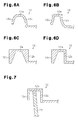
Figs. 6A to 6D are enlarged cross-sectional views illustrating folded portions of door frames according to other embodiments; -
Fig. 7 is an enlarged cross-sectional view illustrating surroundings of the folded portion regarding the door frame according to another embodiment; -
Fig. 8A is a cross-sectional view of the joint forms of the outer member and the inner member in the conventional door frame, illustrating the surroundings of the folded portion in the temporarily coupled state prior to the joint; -
Fig. 8B is a cross-sectional view taken along line D-D; -
Fig. 8C is a cross-sectional view illustrating the surroundings of the folded portion in the state after the joint; -
Fig. 8D is a cross-sectional view taken along line E-E; and -
Fig. 9 is a cross-sectional view illustrating the situation in which a corner portion contacts the facing portion. - Hereinafter, a vehicle door frame according to an embodiment of the present invention will be described.
- As shown in
Fig. 1 , avehicle door 1 supported on the side of a vehicle body includes a door body 2, which configures a lower portion of thevehicle door 1. The door body 2 is a bag-like structure configured by coupling a door outer panel and a door inner panel (not shown). A door window glass DW, which appears and retracts through an upward opening, is provided in the door body 2. - The
vehicle door 1 includes adoor frame 5, which is attached to an upper end portion of the door body 2 and configures a window frame of thevehicle door 1, i.e., the frame of the door window glass DW. Thedoor frame 5 includes apost 5a and a substantially arcuateupper rim 5b. Thepost 5a is fixed to, for example, the door inner panel of the door body 2 in the rear portion in the longitudinal direction of the vehicle and extends in the height direction of the vehicle. Theupper rim 5b is fixed to the door body 2 in the front portion of the vehicle in the longitudinal direction and connected to the upper end of thepost 5a. Thedoor frame 5 opens downward. Thevehicle door 1 of the present embodiment is a front door, which is arranged such that theupper rim 5b and thepost 5a of thedoor frame 5 correspond to an A pillar and a B pillar of the vehicle body. - As shown in
Fig. 2 , thepost 5a includes anouter member 10 formed by press-molding a board such as a steel plate, aninner member 20 formed by press-molding the same board, a sealingmember housing portion 30 with a substantially C-shaped cross section, and anornamental member 40 arranged outward of the vehicle. Theornamental member 40 extends from the portion in the outward direction, i.e., from the rear portion of thevehicle door 1 toward the portion in the inward direction facing the door window glass DW, i.e., toward the front portion of thevehicle door 1. Here, the phrase in the inward direction refers to the direction from thepost 5a toward the central portion of thedoor frame 5. The phrase in the outward direction refers to the direction from thepost 5a toward the rear portion. The plate thickness of theinner member 20 is set greater than the plate thickness of theouter member 10. The end surface of theornamental member 40 exposed outward of the vehicle forms anornamental surface 40a of thepost 5a. The width of theornamental surface 40a gradually changes according to the height direction of the vehicle. This improves the ornamental property of theornamental surface 40a. - The
outer member 10 includes a glass-run housing portion 11 with a substantially U-shaped cross section, which opens in the inward direction of thevehicle door 1. The glass-run housing portion 11 includes aside wall portion 11 a. Theside wall portion 11 a, in the inward direction in the lateral direction of the vehicle, i.e., in the inward direction of the vehicle, extends from the portion in the outward direction of thevehicle door 1 to the portion in the inward direction of thevehicle door 1. A foldedportion 12, which is bent in the outward direction of the vehicle and then folded in the inward direction of the vehicle, is formed on the edge portion of theside wall portion 11 a. As shown inFig. 3 , the foldedportion 12 includes anopening 13, opens in the inward direction of the vehicle. - The
inner member 20 is elongated extending in the vertical direction. Theinner member 20 includes an attachingportion 21 and abody portion 22 with a substantially rectangular cross section. The attachingportion 21 and thebody portion 22 are integrally formed with each other. The attachingportion 21 extends from the portion in the outward direction of thevehicle door 1 to the portion in the inward direction of thevehicle door 1 along the outer portion of the glass-run housing portion 11 and the inner portion of theornamental member 40. Thebody portion 22 is continuous with the inner end of the attachingportion 21, bent in the inward direction of the vehicle and then folded in the outward direction of the vehicle to face theopening 13 of the foldedportion 12. Thebody portion 22 forms the framework of thepost 5a and includes an extendedportion 23, which extends from the portion in the inward direction of the vehicle to the portion in the outward direction of the vehicle in the inward direction of thevehicle door 1. Theinner member 20 is temporarily coupled to theouter member 10 such that the intermediate portion of theinner member 20 is located between theouter member 10 and the sealingmember housing portion 30 and theedge portion 23a of the extendedportion 23 is inserted into theopening 13 of the foldedportion 12. - Next, a manner in which the
outer member 10 and theinner member 20 are joined to each other will be described. - As shown in
Fig. 4 , a plurality ofbasal portions 24, which trapezoidally protrudes in the outward direction of the vehicle, is provided on thedistal end surface 23b of theedge portion 23a of the extendedportion 23 in the longitudinal direction of theinner member 20. Aprotrusion 25, which protrudes in the outward direction of the vehicle, is further formed in the central portion of eachbasal portion 24 in the longitudinal direction. Theprotrusion 25 includes a tip end with a substantially arcuate cross section, which protrudes in the outward direction of the vehicle. That is, the tip end forms a curved surface. The distal end surface of theprotrusion 25 is configured by a group of a plurality of profiles with substantially arcuate cross sections. That is, atip end portion 25b of theprotrusion 25 is formed by cutting a sphere in a certain first plane to obtain a three-dimensional shape and further cutting the obtained three-dimensional shape in two, second and third planes, which are parallel to each other and perpendicular to the first plane. Accordingly, the distal end surface of theprotrusion 25 formed by the three-dimensional shape forms a part of the surface of the sphere. In theprotrusion 25, astraight portion 25a, which maintains the maximum width of the above substantially arcuatetip end portion 25b, is formed in the portion of the root of theprotrusion 25, which is continuous with the tip end with a substantially arcuate cross section. That is, the abovetip end portion 25b with the three-dimensional shape is provided on the substantially square pole-shapedstraight portion 25a as a base. - As shown in
Fig. 5A , the foldedportion 12 includes a firstbent portion 12b and a secondbent portion 12c with a facingportion 12a, which contacts theprotrusion 25 and is located between the first and secondbent portions bent portion 12b is bent in the outward direction of the vehicle to be continuous with the facingportion 12a. The secondbent portion 12c is folded in the inward direction of the vehicle from the facingportion 12a. The foldedportion 12 includes a substantially inverted-U-shaped cross section, which opens wider in the inward direction of the vehicle. That is, each of the firstbent portion 12b and the secondbent portion 12c is separated from the extendedportion 23. Both of the inner surfaces of the firstbent portion 12b and the secondbent portion 12c form inclined surfaces in which the distance from the firstbent portion 12b toward theextended portion 23 and the distance from the secondbent portion 12c toward theextended portion 23 are linearly increased in the inward direction of the vehicle from the facingportion 12a as a starting point. With the facingportion 12a as a starting point, both the inner surface of the firstbent portion 12b and the inner surface of the secondbent portion 12c are gradually separated from the extendedportion 23 in the inward direction of the vehicle. As shown inFig. 5B , in the temporarily coupled state, the gap is defined between the facingportion 12a and eachbasal portion 24 in the lateral direction of the vehicle. - In the temporarily coupled state, the folded
portion 12 and theextended portion 23 are tightly held and pressurized between two welding electrodes of a resistance welding device (not shown), and a welding current flows between the electrodes. Then, as shown inFigs. 5C and 5D , theprotrusion 25 is melted by heating by the concentration of the current so that thebasal portion 24 and the facingportion 12a are pressurized and joined with each other. After the joint, the gap between the facingportion 12a and thebasal portion 24 is filled with the metal from theprotrusion 25 so that the facingportion 12a and thebasal portion 24 contact. As a result, theouter member 10 and theinner member 20 are coupled with each other to be integrated. Thebasal portion 24 is used as a positioning reference when coupling themembers - As shown in
Fig. 2 , a glass-run 45 with a substantially C-shaped cross section formed by, e.g., a rubber material is fluid-tightly provided along the entire length of the glass-run housing portion 11 in the longitudinal direction. The glass-run 45 is provided such that it protrudes greater than the opening end of the glass-run housing portion 11 with a substantially U-shaped cross section to limit the infiltration of water into the glass-run housing portion 11. In particular, the end portion of the glass-run 45 on the side in the inward direction of the vehicle is located in the more inward direction of the vehicle than the foldedportion 12 of theouter member 10 and theedge portion 23a of the extendedportion 23 of theinner member 20. This limits the infiltration of water into the inner space of thepost 5a. Both of the circumferential edges of the door window glass DW on the side in the outward direction of the vehicle and the side in the inward direction of the vehicle can elastically contact the glass-run 45. Accordingly, the glass-run 45 elastically holds the door window glass DW such that the door window glass DW can be opened and closed. - A
body sealing member 46, which fluid-tightly contacts thebody portion 22 along the substantially entire length of theinner member 20 in the longitudinal direction, is held by an opening circumferential edge portion B of the vehicle body facing thepost 5a of thevehicle door 1. Therefore, thepost 5a and the opening circumferential edge portion B are fluid-tightly separated by thebody sealing member 46 with the space between thepost 5a in the outward direction of the vehicle and the opening circumferential edge portion B in the inward direction of the vehicle. - Further, a door sealing member that is not shown is held in the sealing
member housing portion 30. The door sealing member fluid-tightly contacts the opening circumferential edge portion B of the vehicle body along the substantially entire length of theinner member 20 in the longitudinal direction. - Next, operation of the
door frame 5 will be described. - In the temporarily coupling process, the
extended portion 23 of theinner member 20 is inserted into theopening 13 of the foldedportion 12 of theouter member 10 such that theextended portion 23 is tightly held and pressurized in the foldedportion 12. At this time, theextended portion 23 is displaced along the inner surface of the firstbent portion 12b or the inner surface of the secondbent portion 12c so that theextended portion 23 is guided to a position in which the tip end of theprotrusion 25 contacts the facingportion 12a. In the contacting state, the gap is defined between theextended portion 23 and the firstbent portion 12b and between theextended portion 23 and the secondbent portion 12c. If the welding current flows in the contacting state while maintaining the pressurizing and tightly holding of the extendedportion 23 in the foldedportion 12, thetip end portion 25b, which is round and includes no corner portion, of theprotrusion 25 is melted by heating by the concentration of the electric current at the contacting portion. Thetip end portion 25b is gradually heated so that the melting gradually proceeds at the beginning of the welding. At this time, the branch current of the welding current toward portions other than theprotrusion 25 is avoided. Then, in the stage in which the welding is stable, thestraight portion 25a is melted by heating. At this time, a sufficient amount of the melt for fixation is ensured. If the supply of the welding current is suspended while continuing the tightly holding and pressurizing of the extendedportion 23 in the folded portion, the metal configuring theprotrusion 25 is cooled and solidified so that the facingportion 12a and thebasal portion 24 are pressurized and joined with each other. As a result, theouter member 10 and theinner member 20 are coupled with each other to be integrated. - As described above, the present embodiment has the following advantages.
- (1) The
protrusion 25, which serves for the resistance welding includes a tip end shape without a corner portion. This limits the occurrence of spatter. Accordingly, theprotrusion 25 is appropriately melted by heating by the concentration of the electric current during the resistance welding. This appropriately pressurizes and joins thebasal portion 24 provided on thedistal end surface 23b of the extendedportion 23 with the facingportion 12a of the foldedportion 12. The stable quality is obtained after the joint. This allows the stable welding so that the stable quality is maintained after the joint. - (2) The
tip end portion 25b of theprotrusion 25 is melted by heating by the concentration of the electric current during the resistance welding, and then thestraight portion 25a is melted by heating. Accordingly, thetip end portion 25b is melted by heating in the manner in which the spatter does not occur at the beginning of the melting, and then, in the stage in which the melting is stable, thestraight portion 25a is melted by heating. At this time, a sufficient amount of the melt for fixation is ensured. This increases the degree of joint to increase the tensile strength. - (3) Each of the first
bent portion 12b and the secondbent portion 12c is arranged separate from the extendedportion 23. Accordingly, the gap is defined between theextended portion 23 and the firstbent portion 12b and between theextended portion 23 and the secondbent portion 12c. Accordingly, the welding current concentrates on thetarget protrusion 25. That is, the branch current toward portions other than thetarget protrusion 25, i.e., toward theextended portion 23 is prevented. Therefore, the welding is performed with high efficiency. - (4) The extended
portion 23 is inserted into theopening 13 of the foldedportion 12 such that theextended portion 23 is tightly held and pressurized in the foldedportion 12. At this time, theextended portion 23 is displaced along the inclined surface formed by the inner surface of the firstbent portion 12b or the inner surface of the secondbent portion 12c so that theextended portion 23 is guided to a position at which the tip end of theprotrusion 25 contacts the facingportion 12a. This corrects positional shifting so that the welding is performed at a target position. - (5) The distal end surface of the
protrusion 25 forms a curved surface as a part of a spherical surface. Accordingly, when any portion of theprotrusion 25 comes into point contact or planar contact with the facingportion 12a, the portion is more gradually heated so that the melting more gradually proceeds than in the case where the electric current concentrates on the corner portion. Therefore, the occurrence of the spatter is limited so that the stable welding is performed. - The embodiment shown above may be modified as follows.
- Regarding the
protrusion 25, when forming the cross section of the tip end to be arcuate to protrude in the outward direction of the vehicle, the shape of the tip end may be formed to be an arc as a part of an ellipse or a parabola. - As for the
protrusion 25, thestraight portion 25a need not be provided on condition that the amount of the melt for fixation is ensured. For example, asemispherical protrusion 25 including an arcuate cross section with the greater height of the protrusion from thebasal portion 24 may be formed. Thebasal portion 24 need not be provided. That is, thebasal portion 24 may be omitted on condition that another configuration, which serves as a reference for positioning when the members are coupled, is provided, for example. In this case, theprotrusion 25 is directly formed from thedistal end surface 23b. As for theprotrusion 25, theprotrusion 25 in which thestraight portion 25a is formed as well as a roundtip end portion 25b, or theprotrusion 25 in which only the roundtip end portion 25b is formed are permitted. - The
protrusion 25 may include a shape obtained by cutting a column in a plane including an axis of the column, for example. In this case, a part of the circumferential surface of the column is arcuate and theprotrusion 25 extends with a constant cross section. - The inclined surface formed by the inner surface of the first
bent portion 12b and the inner surface of the secondbent portion 12c is not limited to the configuration in which the distance from the firstbent portion 12b toward theextended portion 23 and the distance from the secondbent portion 12c toward theextended portion 23 are linearly increased from the facingportion 12a as a starting point in the inward direction of the vehicle. For example, as shown inFigs. 6A and 6B , the configuration in which the distance from the firstbent portion 12b toward theextended portion 23 and the distance from the secondbent portion 12c toward theextended portion 23 are curvilinearly increased from the facingportion 12a as a starting point in the inward direction of the vehicle may be adopted. Further, as shown inFig. 6C , a configuration may be adopted in which an inclined surface is provided such that the distance from the firstbent portion 12b toward theextended portion 23 and the distance from the secondbent portion 12c toward the extended portion are linearly increased from the facingportion 12a as a starting point in the inward direction of the vehicle and the plate thickness of the inclined surface is reduced from the facingportion 12a as a starting point in the inward direction of the vehicle. Moreover, the combination of the configuration inFigs. 6A and 6B and the configuration inFig. 6C may configure the firstbent portion 12b and the secondbent portion 12c. As shown inFig. 6D , a configuration may be adopted in which the inclined surface is formed by one of the inner surface of the firstbent portion 12b and the inner surface of the secondbent portion 12c. - In the configuration in which the gap is defined between the
extended portion 23 and the firstbent portion 12b and between theextended portion 23 and the secondbent portion 12c as shown inFig. 7 , a configuration may be adopted in which the inclined surface is not formed on the inner surface of the firstbent portion 12b and the inner surface of the secondbent portion 12c and the cross section of the foldedportion 12 is angulated-inverted-U-shaped, which opens downward. Such a configuration also avoids the branch current of the welding current produced by defining the gap. - The
ornamental member 40 may be omitted by adopting theouter member 10 formed integrally with the ornamental portion. In this case, theouter member 10 also serves as an ornamental portion. That is, a part of theouter member 10 is exposed outward of the vehicle. Accordingly, anti-corrosion steel sheet may be used for theouter member 10, for example. - Although the vehicle door frame according to the present invention is applied to the
post 5a of thedoor frame 5 of the front door in the above embodiment, it may be applied to theupper rim 5b of thedoor frame 5 or a door frame, which forms a window frame of the rear door.
Claims (6)
- A vehicle door frame, which forms a window frame of a vehicle door, the door frame comprising:an outer member formed of a board, wherein the outer member forms a glass-run housing portion; andan elongated inner member formed of a board, wherein the inner member includes a body portion for forming a framework of the window frame and is coupled to the outer member, whereinthe outer member includes an edge portion, which forms a part of the glass-run housing portion, and a folded portion provided at the edge portion,the folded portion includes a substantially U-shaped cross section including an opening, which opens in an inward direction of the vehicle,the inner member includes an extended portion, which extends in an outward direction of the vehicle from the body portion, and an edge portion provided at the extended portion,the edge portion of the extended portion is inserted into the opening of the folded portion,the edge portion of the extended portion includes a distal end surface,a protrusion is formed on the distal end surface, wherein the protrusion protrudes in the outward direction of the vehicle and is located at a predetermined position of the inner member in the longitudinal direction,the folded portion has a facing portion that faces the distal end surface,the protrusion can be melted by heating by concentration of electric current during resistance welding and is configured to pressurize and join the distal end surface and the facing portion of the folded portion to each other, andthe protrusion includes a tip end, which has an arcuate cross section protruding in the outward direction of the vehicle.
- The vehicle door frame according to claim 1, wherein the protrusion includes, at a root continuous with the tip end with the arcuate cross section, a straight portion with a width the same as a maximum width of the tip end.
- The vehicle door frame according to claim 1 or 2, wherein
the folded portion includes a first bent portion and a second bent portion, which are arranged on both sides of the facing portion, which the protrusion contacts,
the first bent portion is folded in the outward direction of the vehicle and continuous with the facing portion,
the second bent portion is folded in the inward direction of the vehicle from the facing portion, and
the first bent portion and the second bent portion are arranged separate from the extended portion. - The vehicle door frame according to claim 3, wherein at least one of an inner surface of the first bent portion and an inner surface of the second bent portion is, with the facing portion as a starting point, gradually separated away from the extended portion in the inward direction of the vehicle.
- The vehicle door frame according to claim 1 or 2, wherein the tip end of the protrusion is formed by a group of a plurality of profiles with arcuate cross sections.
- An inner member adapted to a vehicle door frame forming a window frame of a vehicle door and configured to be coupled to an outer member, which is formed of a board and forms a glass-run housing portion, wherein
the outer member includes an edge portion, which forms a part of the glass-run housing portion, and a folded portion provided at the edge portion,
the folded portion includes a substantially U-shaped cross section including an opening, which opens in an inward direction of the vehicle,
the inner member is configured such that the inner member is formed of a board, includes a body portion, which forms a framework of the window frame, and is elongated,
the inner member includes an extended portion, which extends in an outward direction of the vehicle from the body portion, and an edge portion provided at the extended portion, the edge portion of the extended portion is inserted into the opening of the folded portion,
the edge portion of the extended portion includes a distal end surface,
a protrusion is formed on the distal end surface, wherein the protrusion protrudes in the outward direction of the vehicle, and is located at a predetermined position of the inner member in the longitudinal direction,
the folded portion has a facing portion that faces the distal end surface,
the protrusion can be melted by heating by concentration of electric current during resistance welding, and is configured to pressurize and join the distal end surface and the facing portion of the folded portion to each other, and
the protrusion includes a tip end, which has an arcuate cross section protruding in the outward direction of the vehicle.
Applications Claiming Priority (2)
| Application Number | Priority Date | Filing Date | Title |
|---|---|---|---|
| JP2011270414A JP5859836B2 (en) | 2011-12-09 | 2011-12-09 | Temporary assembly structure of vehicle door frame |
| PCT/JP2012/081024 WO2013084801A1 (en) | 2011-12-09 | 2012-11-30 | Vehicle door frame and inner member for vehicle door frame |
Publications (3)
| Publication Number | Publication Date |
|---|---|
| EP2789483A1 true EP2789483A1 (en) | 2014-10-15 |
| EP2789483A4 EP2789483A4 (en) | 2016-01-13 |
| EP2789483B1 EP2789483B1 (en) | 2019-11-20 |
Family
ID=48574170
Family Applications (1)
| Application Number | Title | Priority Date | Filing Date |
|---|---|---|---|
| EP12855552.1A Active EP2789483B1 (en) | 2011-12-09 | 2012-11-30 | Vehicle door frame and inner member for vehicle door frame |
Country Status (7)
| Country | Link |
|---|---|
| US (1) | US9199525B2 (en) |
| EP (1) | EP2789483B1 (en) |
| JP (1) | JP5859836B2 (en) |
| CN (1) | CN103987550B (en) |
| BR (1) | BR112014013404B1 (en) |
| CA (1) | CA2858018C (en) |
| WO (1) | WO2013084801A1 (en) |
Families Citing this family (11)
| Publication number | Priority date | Publication date | Assignee | Title |
|---|---|---|---|---|
| JP5352396B2 (en) * | 2009-09-24 | 2013-11-27 | アイシン精機株式会社 | Vehicle door frame |
| JP6368708B2 (en) * | 2013-04-05 | 2018-08-01 | シロキ工業株式会社 | Door sash with sash for vehicle |
| DE102013213109A1 (en) * | 2013-07-04 | 2015-01-22 | Ford Global Technologies, Llc | Method for the permanent connection of components or component areas as well as permanent connection |
| EP3040224B1 (en) * | 2013-08-30 | 2020-04-01 | Aisin Seiki Kabushiki Kaisha | Vehicular door frame, and vehicular door frame intermediary member |
| JP6165691B2 (en) * | 2014-09-04 | 2017-07-19 | 三恵技研工業株式会社 | Door sash and manufacturing method thereof |
| KR101655593B1 (en) | 2014-12-05 | 2016-09-07 | 현대자동차주식회사 | Welding device of automobile parts |
| KR101664610B1 (en) * | 2014-12-05 | 2016-10-10 | 현대자동차주식회사 | Welding device and welding system of automobile parts |
| US10369654B2 (en) * | 2015-02-09 | 2019-08-06 | Origin Company, Limited | Welded article and method for manufacturing welded article |
| US20170144515A1 (en) * | 2015-11-24 | 2017-05-25 | Shiroki Corporation | Vehicle door sash |
| JP6748538B2 (en) * | 2016-09-21 | 2020-09-02 | シロキ工業株式会社 | Vehicle door frame |
| JP6731327B2 (en) * | 2016-11-02 | 2020-07-29 | シロキ工業株式会社 | Door frame |
Family Cites Families (19)
| Publication number | Priority date | Publication date | Assignee | Title |
|---|---|---|---|---|
| DE3345617C1 (en) * | 1983-12-16 | 1985-01-10 | Daimler-Benz Ag, 7000 Stuttgart | Weld-on nut for a ground connection point on sheet metal components |
| US6054668A (en) * | 1997-07-17 | 2000-04-25 | Newcor, Inc. | Method and apparatus of projection welding |
| JP3568369B2 (en) * | 1997-07-22 | 2004-09-22 | オリジン電気株式会社 | Welding method of workpiece |
| US6621037B2 (en) | 1997-10-16 | 2003-09-16 | Magna International Inc. | Welding material with conductive sheet and method |
| US6623067B2 (en) | 1997-10-16 | 2003-09-23 | Magna International Inc. | Door seal interface structure for a motor vehicle space frame |
| US6302478B1 (en) | 1997-10-16 | 2001-10-16 | Cosma International Inc. | Hydroformed space frame joints therefor |
| US6346684B1 (en) | 1997-10-16 | 2002-02-12 | Cosma International Inc. | Welding material assembly and method |
| US6533348B1 (en) | 1997-10-16 | 2003-03-18 | Cosma International Inc. | Modular space frame |
| US6739624B2 (en) | 1997-10-16 | 2004-05-25 | Magna International Inc. | Frame assembly for a motor vehicle |
| US6713707B2 (en) | 1997-10-16 | 2004-03-30 | Magna International, Inc. | Welding material and method without carrier |
| US6689982B2 (en) | 1997-10-16 | 2004-02-10 | Magna International, Inc. | Apparatus and method for welding aluminum tubes |
| UY25215A1 (en) | 1997-10-16 | 1999-04-09 | Cosma Int Inc | SPECIAL HYDROFORMED CASE AND METHOD FOR THE MANUFACTURE OF THE SAME |
| US6566624B2 (en) | 2000-03-03 | 2003-05-20 | Magna International Inc. | Welding assembly with nestable conductive ends |
| JP3838335B2 (en) * | 2001-02-08 | 2006-10-25 | トヨタ自動車株式会社 | Two-member joining method |
| JP4155395B2 (en) * | 2002-07-11 | 2008-09-24 | ダイハツ工業株式会社 | Projection welding method |
| JP2005259920A (en) * | 2004-03-11 | 2005-09-22 | Hanshin Electric Co Ltd | Ignition coil for internal combustion engine |
| JP5352396B2 (en) * | 2009-09-24 | 2013-11-27 | アイシン精機株式会社 | Vehicle door frame |
| JP2012059365A (en) * | 2010-09-03 | 2012-03-22 | Sanyo Electric Co Ltd | Terminal for sealed battery and method of manufacturing the same |
| KR101439147B1 (en) * | 2013-04-19 | 2014-09-11 | 현대자동차주식회사 | Connecting structure and method of side structure and roof rail |
-
2011
- 2011-12-09 JP JP2011270414A patent/JP5859836B2/en active Active
-
2012
- 2012-11-30 CN CN201280058806.5A patent/CN103987550B/en active Active
- 2012-11-30 CA CA2858018A patent/CA2858018C/en active Active
- 2012-11-30 US US14/363,073 patent/US9199525B2/en active Active
- 2012-11-30 EP EP12855552.1A patent/EP2789483B1/en active Active
- 2012-11-30 WO PCT/JP2012/081024 patent/WO2013084801A1/en not_active Ceased
- 2012-11-30 BR BR112014013404-9A patent/BR112014013404B1/en active IP Right Grant
Also Published As
| Publication number | Publication date |
|---|---|
| CA2858018A1 (en) | 2013-06-13 |
| WO2013084801A1 (en) | 2013-06-13 |
| EP2789483B1 (en) | 2019-11-20 |
| US20140339853A1 (en) | 2014-11-20 |
| EP2789483A4 (en) | 2016-01-13 |
| JP2013121754A (en) | 2013-06-20 |
| CN103987550B (en) | 2016-06-22 |
| BR112014013404B1 (en) | 2021-01-26 |
| US9199525B2 (en) | 2015-12-01 |
| CN103987550A (en) | 2014-08-13 |
| CA2858018C (en) | 2016-11-08 |
| BR112014013404A2 (en) | 2017-06-13 |
| JP5859836B2 (en) | 2016-02-16 |
Similar Documents
| Publication | Publication Date | Title |
|---|---|---|
| US9199525B2 (en) | Vehicle door frame and inner member for vehicle door frame | |
| US20160200181A1 (en) | Vehicular door frame, and vehicular door frame intermediary member | |
| EP2631158A1 (en) | Vehicle body structure | |
| CN104334383B (en) | Door frame and its manufacture method | |
| KR102055764B1 (en) | Overlap welding method of steel plate and overlap welding joint | |
| CN204236567U (en) | Extruding vehicle back timber, for the extruding back timber of vehicle frame and vehicle frame | |
| US20180265138A1 (en) | Rear body structure | |
| US10259297B2 (en) | Vehicle door frame | |
| KR101620055B1 (en) | Connection element of the headrest poles on a seat structure | |
| US20180043939A1 (en) | Vehicle front pillar | |
| CN104276011B (en) | Vehicle door | |
| CN110091697B (en) | Door sash structure and car door and car | |
| CN114162221B (en) | Roof structure of vehicle | |
| JP2015199471A (en) | Upright pillar sash of vehicle door, and method for manufacturing upright pillar sash of vehicle door | |
| JP5708536B2 (en) | Vehicle roof structure | |
| CN110985873B (en) | Column section bar | |
| CN214424836U (en) | Connecting structure of panel | |
| JP5315303B2 (en) | Rail vehicle structure | |
| CN204299402U (en) | A kind of structure of French casement | |
| JP5370652B2 (en) | Cabin side structure having a tubular frame disposed at the periphery of the door opening and its assembling method | |
| CN217197734U (en) | Door sash ROOF section of car | |
| CN219969353U (en) | Triangular window structure and vehicle | |
| CN209833791U (en) | Automobile framework auxiliary beam | |
| CN206426815U (en) | Window frame attachment structure | |
| JP2014073759A (en) | Division bar structure |
Legal Events
| Date | Code | Title | Description |
|---|---|---|---|
| PUAI | Public reference made under article 153(3) epc to a published international application that has entered the european phase |
Free format text: ORIGINAL CODE: 0009012 |
|
| 17P | Request for examination filed |
Effective date: 20140522 |
|
| AK | Designated contracting states |
Kind code of ref document: A1 Designated state(s): AL AT BE BG CH CY CZ DE DK EE ES FI FR GB GR HR HU IE IS IT LI LT LU LV MC MK MT NL NO PL PT RO RS SE SI SK SM TR |
|
| DAX | Request for extension of the european patent (deleted) | ||
| RA4 | Supplementary search report drawn up and despatched (corrected) |
Effective date: 20151216 |
|
| RIC1 | Information provided on ipc code assigned before grant |
Ipc: B60J 5/04 20060101AFI20151210BHEP Ipc: B23K 11/14 20060101ALI20151210BHEP Ipc: B23K 11/00 20060101ALI20151210BHEP |
|
| STAA | Information on the status of an ep patent application or granted ep patent |
Free format text: STATUS: EXAMINATION IS IN PROGRESS |
|
| 17Q | First examination report despatched |
Effective date: 20180712 |
|
| REG | Reference to a national code |
Ref country code: DE Ref legal event code: R079 Ref document number: 602012065907 Country of ref document: DE Free format text: PREVIOUS MAIN CLASS: B60J0005040000 Ipc: B23K0011110000 |
|
| RIC1 | Information provided on ipc code assigned before grant |
Ipc: B23K 11/14 20060101ALI20190409BHEP Ipc: B23K 103/04 20060101ALI20190409BHEP Ipc: B23K 101/00 20060101ALI20190409BHEP Ipc: B23K 33/00 20060101ALI20190409BHEP Ipc: B23K 101/18 20060101ALI20190409BHEP Ipc: B23K 11/11 20060101AFI20190409BHEP Ipc: B60J 5/04 20060101ALI20190409BHEP |
|
| GRAP | Despatch of communication of intention to grant a patent |
Free format text: ORIGINAL CODE: EPIDOSNIGR1 |
|
| STAA | Information on the status of an ep patent application or granted ep patent |
Free format text: STATUS: GRANT OF PATENT IS INTENDED |
|
| INTG | Intention to grant announced |
Effective date: 20190531 |
|
| GRAS | Grant fee paid |
Free format text: ORIGINAL CODE: EPIDOSNIGR3 |
|
| GRAA | (expected) grant |
Free format text: ORIGINAL CODE: 0009210 |
|
| STAA | Information on the status of an ep patent application or granted ep patent |
Free format text: STATUS: THE PATENT HAS BEEN GRANTED |
|
| AK | Designated contracting states |
Kind code of ref document: B1 Designated state(s): AL AT BE BG CH CY CZ DE DK EE ES FI FR GB GR HR HU IE IS IT LI LT LU LV MC MK MT NL NO PL PT RO RS SE SI SK SM TR |
|
| REG | Reference to a national code |
Ref country code: GB Ref legal event code: FG4D |
|
| REG | Reference to a national code |
Ref country code: CH Ref legal event code: EP |
|
| REG | Reference to a national code |
Ref country code: IE Ref legal event code: FG4D |
|
| REG | Reference to a national code |
Ref country code: DE Ref legal event code: R096 Ref document number: 602012065907 Country of ref document: DE |
|
| REG | Reference to a national code |
Ref country code: AT Ref legal event code: REF Ref document number: 1203646 Country of ref document: AT Kind code of ref document: T Effective date: 20191215 |
|
| REG | Reference to a national code |
Ref country code: NL Ref legal event code: MP Effective date: 20191120 |
|
| REG | Reference to a national code |
Ref country code: LT Ref legal event code: MG4D |
|
| PG25 | Lapsed in a contracting state [announced via postgrant information from national office to epo] |
Ref country code: FI Free format text: LAPSE BECAUSE OF FAILURE TO SUBMIT A TRANSLATION OF THE DESCRIPTION OR TO PAY THE FEE WITHIN THE PRESCRIBED TIME-LIMIT Effective date: 20191120 Ref country code: NO Free format text: LAPSE BECAUSE OF FAILURE TO SUBMIT A TRANSLATION OF THE DESCRIPTION OR TO PAY THE FEE WITHIN THE PRESCRIBED TIME-LIMIT Effective date: 20200220 Ref country code: BG Free format text: LAPSE BECAUSE OF FAILURE TO SUBMIT A TRANSLATION OF THE DESCRIPTION OR TO PAY THE FEE WITHIN THE PRESCRIBED TIME-LIMIT Effective date: 20200220 Ref country code: SE Free format text: LAPSE BECAUSE OF FAILURE TO SUBMIT A TRANSLATION OF THE DESCRIPTION OR TO PAY THE FEE WITHIN THE PRESCRIBED TIME-LIMIT Effective date: 20191120 Ref country code: LV Free format text: LAPSE BECAUSE OF FAILURE TO SUBMIT A TRANSLATION OF THE DESCRIPTION OR TO PAY THE FEE WITHIN THE PRESCRIBED TIME-LIMIT Effective date: 20191120 Ref country code: LT Free format text: LAPSE BECAUSE OF FAILURE TO SUBMIT A TRANSLATION OF THE DESCRIPTION OR TO PAY THE FEE WITHIN THE PRESCRIBED TIME-LIMIT Effective date: 20191120 Ref country code: GR Free format text: LAPSE BECAUSE OF FAILURE TO SUBMIT A TRANSLATION OF THE DESCRIPTION OR TO PAY THE FEE WITHIN THE PRESCRIBED TIME-LIMIT Effective date: 20200221 Ref country code: NL Free format text: LAPSE BECAUSE OF FAILURE TO SUBMIT A TRANSLATION OF THE DESCRIPTION OR TO PAY THE FEE WITHIN THE PRESCRIBED TIME-LIMIT Effective date: 20191120 Ref country code: ES Free format text: LAPSE BECAUSE OF FAILURE TO SUBMIT A TRANSLATION OF THE DESCRIPTION OR TO PAY THE FEE WITHIN THE PRESCRIBED TIME-LIMIT Effective date: 20191120 |
|
| PG25 | Lapsed in a contracting state [announced via postgrant information from national office to epo] |
Ref country code: IS Free format text: LAPSE BECAUSE OF FAILURE TO SUBMIT A TRANSLATION OF THE DESCRIPTION OR TO PAY THE FEE WITHIN THE PRESCRIBED TIME-LIMIT Effective date: 20200320 Ref country code: HR Free format text: LAPSE BECAUSE OF FAILURE TO SUBMIT A TRANSLATION OF THE DESCRIPTION OR TO PAY THE FEE WITHIN THE PRESCRIBED TIME-LIMIT Effective date: 20191120 Ref country code: RS Free format text: LAPSE BECAUSE OF FAILURE TO SUBMIT A TRANSLATION OF THE DESCRIPTION OR TO PAY THE FEE WITHIN THE PRESCRIBED TIME-LIMIT Effective date: 20191120 |
|
| PG25 | Lapsed in a contracting state [announced via postgrant information from national office to epo] |
Ref country code: AL Free format text: LAPSE BECAUSE OF FAILURE TO SUBMIT A TRANSLATION OF THE DESCRIPTION OR TO PAY THE FEE WITHIN THE PRESCRIBED TIME-LIMIT Effective date: 20191120 |
|
| REG | Reference to a national code |
Ref country code: CH Ref legal event code: PL |
|
| PG25 | Lapsed in a contracting state [announced via postgrant information from national office to epo] |
Ref country code: LU Free format text: LAPSE BECAUSE OF NON-PAYMENT OF DUE FEES Effective date: 20191130 Ref country code: DK Free format text: LAPSE BECAUSE OF FAILURE TO SUBMIT A TRANSLATION OF THE DESCRIPTION OR TO PAY THE FEE WITHIN THE PRESCRIBED TIME-LIMIT Effective date: 20191120 Ref country code: EE Free format text: LAPSE BECAUSE OF FAILURE TO SUBMIT A TRANSLATION OF THE DESCRIPTION OR TO PAY THE FEE WITHIN THE PRESCRIBED TIME-LIMIT Effective date: 20191120 Ref country code: PT Free format text: LAPSE BECAUSE OF FAILURE TO SUBMIT A TRANSLATION OF THE DESCRIPTION OR TO PAY THE FEE WITHIN THE PRESCRIBED TIME-LIMIT Effective date: 20200412 Ref country code: CZ Free format text: LAPSE BECAUSE OF FAILURE TO SUBMIT A TRANSLATION OF THE DESCRIPTION OR TO PAY THE FEE WITHIN THE PRESCRIBED TIME-LIMIT Effective date: 20191120 Ref country code: RO Free format text: LAPSE BECAUSE OF FAILURE TO SUBMIT A TRANSLATION OF THE DESCRIPTION OR TO PAY THE FEE WITHIN THE PRESCRIBED TIME-LIMIT Effective date: 20191120 Ref country code: LI Free format text: LAPSE BECAUSE OF NON-PAYMENT OF DUE FEES Effective date: 20191130 Ref country code: CH Free format text: LAPSE BECAUSE OF NON-PAYMENT OF DUE FEES Effective date: 20191130 |
|
| REG | Reference to a national code |
Ref country code: AT Ref legal event code: MK05 Ref document number: 1203646 Country of ref document: AT Kind code of ref document: T Effective date: 20191120 |
|
| REG | Reference to a national code |
Ref country code: BE Ref legal event code: MM Effective date: 20191130 Ref country code: DE Ref legal event code: R097 Ref document number: 602012065907 Country of ref document: DE |
|
| PG25 | Lapsed in a contracting state [announced via postgrant information from national office to epo] |
Ref country code: MC Free format text: LAPSE BECAUSE OF FAILURE TO SUBMIT A TRANSLATION OF THE DESCRIPTION OR TO PAY THE FEE WITHIN THE PRESCRIBED TIME-LIMIT Effective date: 20191120 Ref country code: SK Free format text: LAPSE BECAUSE OF FAILURE TO SUBMIT A TRANSLATION OF THE DESCRIPTION OR TO PAY THE FEE WITHIN THE PRESCRIBED TIME-LIMIT Effective date: 20191120 Ref country code: SM Free format text: LAPSE BECAUSE OF FAILURE TO SUBMIT A TRANSLATION OF THE DESCRIPTION OR TO PAY THE FEE WITHIN THE PRESCRIBED TIME-LIMIT Effective date: 20191120 |
|
| PLBE | No opposition filed within time limit |
Free format text: ORIGINAL CODE: 0009261 |
|
| STAA | Information on the status of an ep patent application or granted ep patent |
Free format text: STATUS: NO OPPOSITION FILED WITHIN TIME LIMIT |
|
| 26N | No opposition filed |
Effective date: 20200821 |
|
| GBPC | Gb: european patent ceased through non-payment of renewal fee |
Effective date: 20200220 |
|
| PG25 | Lapsed in a contracting state [announced via postgrant information from national office to epo] |
Ref country code: IE Free format text: LAPSE BECAUSE OF NON-PAYMENT OF DUE FEES Effective date: 20191130 |
|
| PG25 | Lapsed in a contracting state [announced via postgrant information from national office to epo] |
Ref country code: AT Free format text: LAPSE BECAUSE OF FAILURE TO SUBMIT A TRANSLATION OF THE DESCRIPTION OR TO PAY THE FEE WITHIN THE PRESCRIBED TIME-LIMIT Effective date: 20191120 Ref country code: SI Free format text: LAPSE BECAUSE OF FAILURE TO SUBMIT A TRANSLATION OF THE DESCRIPTION OR TO PAY THE FEE WITHIN THE PRESCRIBED TIME-LIMIT Effective date: 20191120 Ref country code: BE Free format text: LAPSE BECAUSE OF NON-PAYMENT OF DUE FEES Effective date: 20191130 Ref country code: PL Free format text: LAPSE BECAUSE OF FAILURE TO SUBMIT A TRANSLATION OF THE DESCRIPTION OR TO PAY THE FEE WITHIN THE PRESCRIBED TIME-LIMIT Effective date: 20191120 |
|
| PG25 | Lapsed in a contracting state [announced via postgrant information from national office to epo] |
Ref country code: GB Free format text: LAPSE BECAUSE OF NON-PAYMENT OF DUE FEES Effective date: 20200220 Ref country code: IT Free format text: LAPSE BECAUSE OF FAILURE TO SUBMIT A TRANSLATION OF THE DESCRIPTION OR TO PAY THE FEE WITHIN THE PRESCRIBED TIME-LIMIT Effective date: 20191120 |
|
| PG25 | Lapsed in a contracting state [announced via postgrant information from national office to epo] |
Ref country code: CY Free format text: LAPSE BECAUSE OF FAILURE TO SUBMIT A TRANSLATION OF THE DESCRIPTION OR TO PAY THE FEE WITHIN THE PRESCRIBED TIME-LIMIT Effective date: 20191120 |
|
| PG25 | Lapsed in a contracting state [announced via postgrant information from national office to epo] |
Ref country code: HU Free format text: LAPSE BECAUSE OF FAILURE TO SUBMIT A TRANSLATION OF THE DESCRIPTION OR TO PAY THE FEE WITHIN THE PRESCRIBED TIME-LIMIT; INVALID AB INITIO Effective date: 20121130 Ref country code: MT Free format text: LAPSE BECAUSE OF FAILURE TO SUBMIT A TRANSLATION OF THE DESCRIPTION OR TO PAY THE FEE WITHIN THE PRESCRIBED TIME-LIMIT Effective date: 20191120 |
|
| PG25 | Lapsed in a contracting state [announced via postgrant information from national office to epo] |
Ref country code: MK Free format text: LAPSE BECAUSE OF FAILURE TO SUBMIT A TRANSLATION OF THE DESCRIPTION OR TO PAY THE FEE WITHIN THE PRESCRIBED TIME-LIMIT Effective date: 20191120 |
|
| PGFP | Annual fee paid to national office [announced via postgrant information from national office to epo] |
Ref country code: FR Payment date: 20250930 Year of fee payment: 14 |
|
| PGFP | Annual fee paid to national office [announced via postgrant information from national office to epo] |
Ref country code: DE Payment date: 20250930 Year of fee payment: 14 |
|
| PGFP | Annual fee paid to national office [announced via postgrant information from national office to epo] |
Ref country code: TR Payment date: 20251127 Year of fee payment: 14 |