EP2789409A1 - Autofrettage machining device - Google Patents
Autofrettage machining device Download PDFInfo
- Publication number
- EP2789409A1 EP2789409A1 EP12854910.2A EP12854910A EP2789409A1 EP 2789409 A1 EP2789409 A1 EP 2789409A1 EP 12854910 A EP12854910 A EP 12854910A EP 2789409 A1 EP2789409 A1 EP 2789409A1
- Authority
- EP
- European Patent Office
- Prior art keywords
- work
- piston
- end opening
- jig
- feed speed
- Prior art date
- Legal status (The legal status is an assumption and is not a legal conclusion. Google has not performed a legal analysis and makes no representation as to the accuracy of the status listed.)
- Granted
Links
- 238000003754 machining Methods 0.000 title abstract description 3
- 238000004891 communication Methods 0.000 claims abstract description 3
- 239000002184 metal Substances 0.000 claims description 6
- 229910052751 metal Inorganic materials 0.000 claims description 6
- 238000003825 pressing Methods 0.000 claims description 4
- 239000006227 byproduct Substances 0.000 abstract 1
- 239000010720 hydraulic oil Substances 0.000 abstract 1
- 239000003921 oil Substances 0.000 description 53
- 239000000446 fuel Substances 0.000 description 28
- RTZKZFJDLAIYFH-UHFFFAOYSA-N Diethyl ether Chemical compound CCOCC RTZKZFJDLAIYFH-UHFFFAOYSA-N 0.000 description 12
- 238000000034 method Methods 0.000 description 11
- 238000012986 modification Methods 0.000 description 11
- 230000004048 modification Effects 0.000 description 11
- 239000000047 product Substances 0.000 description 11
- 238000003780 insertion Methods 0.000 description 8
- 230000037431 insertion Effects 0.000 description 8
- 230000008569 process Effects 0.000 description 8
- 238000007789 sealing Methods 0.000 description 8
- 229920006395 saturated elastomer Polymers 0.000 description 7
- 239000000243 solution Substances 0.000 description 3
- 230000008859 change Effects 0.000 description 2
- 230000007423 decrease Effects 0.000 description 2
- 238000013461 design Methods 0.000 description 2
- 230000000694 effects Effects 0.000 description 2
- 239000012467 final product Substances 0.000 description 2
- 239000007788 liquid Substances 0.000 description 2
- 238000011160 research Methods 0.000 description 2
- RYGMFSIKBFXOCR-UHFFFAOYSA-N Copper Chemical compound [Cu] RYGMFSIKBFXOCR-UHFFFAOYSA-N 0.000 description 1
- VGGSQFUCUMXWEO-UHFFFAOYSA-N Ethene Chemical compound C=C VGGSQFUCUMXWEO-UHFFFAOYSA-N 0.000 description 1
- JOYRKODLDBILNP-UHFFFAOYSA-N Ethyl urethane Chemical compound CCOC(N)=O JOYRKODLDBILNP-UHFFFAOYSA-N 0.000 description 1
- 239000005977 Ethylene Substances 0.000 description 1
- 239000002202 Polyethylene glycol Substances 0.000 description 1
- 230000009471 action Effects 0.000 description 1
- 150000005215 alkyl ethers Chemical class 0.000 description 1
- 125000000484 butyl group Chemical group [H]C([*])([H])C([H])([H])C([H])([H])C([H])([H])[H] 0.000 description 1
- YACLQRRMGMJLJV-UHFFFAOYSA-N chloroprene Chemical compound ClC(=C)C=C YACLQRRMGMJLJV-UHFFFAOYSA-N 0.000 description 1
- 230000006835 compression Effects 0.000 description 1
- 238000007906 compression Methods 0.000 description 1
- 229910052802 copper Inorganic materials 0.000 description 1
- 239000010949 copper Substances 0.000 description 1
- 150000001983 dialkylethers Chemical class 0.000 description 1
- 230000005489 elastic deformation Effects 0.000 description 1
- 238000002474 experimental method Methods 0.000 description 1
- 239000012530 fluid Substances 0.000 description 1
- 239000002828 fuel tank Substances 0.000 description 1
- 238000002347 injection Methods 0.000 description 1
- 239000007924 injection Substances 0.000 description 1
- 238000004519 manufacturing process Methods 0.000 description 1
- 239000000463 material Substances 0.000 description 1
- 150000002825 nitriles Chemical class 0.000 description 1
- 229920001223 polyethylene glycol Polymers 0.000 description 1
- 229920002503 polyoxyethylene-polyoxypropylene Polymers 0.000 description 1
- -1 polyoxypropylene Polymers 0.000 description 1
- 229920001451 polypropylene glycol Polymers 0.000 description 1
- 230000009467 reduction Effects 0.000 description 1
- 238000006748 scratching Methods 0.000 description 1
- 230000002393 scratching effect Effects 0.000 description 1
- 230000001629 suppression Effects 0.000 description 1
- 230000003746 surface roughness Effects 0.000 description 1
- 150000005691 triesters Chemical class 0.000 description 1
Images








Classifications
-
- B—PERFORMING OPERATIONS; TRANSPORTING
- B23—MACHINE TOOLS; METAL-WORKING NOT OTHERWISE PROVIDED FOR
- B23P—METAL-WORKING NOT OTHERWISE PROVIDED FOR; COMBINED OPERATIONS; UNIVERSAL MACHINE TOOLS
- B23P9/00—Treating or finishing surfaces mechanically, with or without calibrating, primarily to resist wear or impact, e.g. smoothing or roughening turbine blades or bearings; Features of such surfaces not otherwise provided for, their treatment being unspecified
-
- F—MECHANICAL ENGINEERING; LIGHTING; HEATING; WEAPONS; BLASTING
- F02—COMBUSTION ENGINES; HOT-GAS OR COMBUSTION-PRODUCT ENGINE PLANTS
- F02M—SUPPLYING COMBUSTION ENGINES IN GENERAL WITH COMBUSTIBLE MIXTURES OR CONSTITUENTS THEREOF
- F02M55/00—Fuel-injection apparatus characterised by their fuel conduits or their venting means; Arrangements of conduits between fuel tank and pump F02M37/00
-
- F—MECHANICAL ENGINEERING; LIGHTING; HEATING; WEAPONS; BLASTING
- F02—COMBUSTION ENGINES; HOT-GAS OR COMBUSTION-PRODUCT ENGINE PLANTS
- F02M—SUPPLYING COMBUSTION ENGINES IN GENERAL WITH COMBUSTIBLE MIXTURES OR CONSTITUENTS THEREOF
- F02M55/00—Fuel-injection apparatus characterised by their fuel conduits or their venting means; Arrangements of conduits between fuel tank and pump F02M37/00
- F02M55/02—Conduits between injection pumps and injectors, e.g. conduits between pump and common-rail or conduits between common-rail and injectors
-
- F—MECHANICAL ENGINEERING; LIGHTING; HEATING; WEAPONS; BLASTING
- F02—COMBUSTION ENGINES; HOT-GAS OR COMBUSTION-PRODUCT ENGINE PLANTS
- F02M—SUPPLYING COMBUSTION ENGINES IN GENERAL WITH COMBUSTIBLE MIXTURES OR CONSTITUENTS THEREOF
- F02M61/00—Fuel-injectors not provided for in groups F02M39/00 - F02M57/00 or F02M67/00
- F02M61/16—Details not provided for in, or of interest apart from, the apparatus of groups F02M61/02 - F02M61/14
- F02M61/168—Assembling; Disassembling; Manufacturing; Adjusting
-
- F—MECHANICAL ENGINEERING; LIGHTING; HEATING; WEAPONS; BLASTING
- F02—COMBUSTION ENGINES; HOT-GAS OR COMBUSTION-PRODUCT ENGINE PLANTS
- F02M—SUPPLYING COMBUSTION ENGINES IN GENERAL WITH COMBUSTIBLE MIXTURES OR CONSTITUENTS THEREOF
- F02M2200/00—Details of fuel-injection apparatus, not otherwise provided for
- F02M2200/03—Fuel-injection apparatus having means for reducing or avoiding stress, e.g. the stress caused by mechanical force, by fluid pressure or by temperature variations
-
- F—MECHANICAL ENGINEERING; LIGHTING; HEATING; WEAPONS; BLASTING
- F02—COMBUSTION ENGINES; HOT-GAS OR COMBUSTION-PRODUCT ENGINE PLANTS
- F02M—SUPPLYING COMBUSTION ENGINES IN GENERAL WITH COMBUSTIBLE MIXTURES OR CONSTITUENTS THEREOF
- F02M2200/00—Details of fuel-injection apparatus, not otherwise provided for
- F02M2200/80—Fuel injection apparatus manufacture, repair or assembly
- F02M2200/8053—Fuel injection apparatus manufacture, repair or assembly involving mechanical deformation of the apparatus or parts thereof
-
- F—MECHANICAL ENGINEERING; LIGHTING; HEATING; WEAPONS; BLASTING
- F02—COMBUSTION ENGINES; HOT-GAS OR COMBUSTION-PRODUCT ENGINE PLANTS
- F02M—SUPPLYING COMBUSTION ENGINES IN GENERAL WITH COMBUSTIBLE MIXTURES OR CONSTITUENTS THEREOF
- F02M2200/00—Details of fuel-injection apparatus, not otherwise provided for
- F02M2200/90—Selection of particular materials
- F02M2200/9053—Metals
- F02M2200/9061—Special treatments for modifying the properties of metals used for fuel injection apparatus, e.g. modifying mechanical or electromagnetic properties
Definitions
- the present invention for example, relates to an autofrettage apparatus which is used for a machine for forming a high pressure fuel injection pipe or a common rail etc., in particular one operating under a superhigh pressure.
- autofrettage the process of applying a high pressure in a sealed state so as to leave residual stress in the structure of a material and thereby raise its strength. That is, in autofrettage, high pressure is given to the inside of a work so as to cause plastic deformation at the inside of the work and so as to cause elastic deformation, but not cause plastic deformation at the outside of the work. Due to this, residual compressive stress is given to the work and the work is increased in fatigue strength limit. This process is being utilized for diesel common rail system parts and other parts where a high fatigue strength limit is required for the purpose of imparting residual compressive stress aimed at increasing the fatigue strength.
- PLT 1 discloses a process which directly inserts a piston of a pressurizing cylinder inside a work so as to raise the pressure.
- this process due to the shape of the work covered by the process (fine bore, short ducts, etc.), various restrictions arose such as an insufficient stroke at the time of raising the pressure or the inability of the piston to be inserted into the work.
- the present invention was made in consideration of the above problem and provides a solution to the various restrictions which arise due to the product shape etc.
- an autofrettage apparatus comprising a work (1) having a work end opening (14) and internal chamber (IC), wherein the internal chamber (IC) is closed except at the work end opening (14) and working oil (2) is filled from the work end opening (14) to the internal chamber (IC); a jig (51) which can be attached to or detached from the work (1) and has a straight channel (52) at its inside, the straight channel (52) being configured so as to communicate with the work end opening (14) without leakage through a seal part (55); a piston (42) which forms a clearance (3) which has a predetermined average clearance amount (h) with respect to an inside wall of the straight channel (52) which is provided at the inside of the jig; and a pressurizing part (40) which drives the piston (42), wherein the pressurizing part (40) drives the piston (42) so that the piston (42) becomes a predetermined feed speed (v) in the straight channel (52) which is filled by the working oil (2), and the predetermined
- the aspect of the invention of claim 2 comprises the aspect of the invention of claim 1 characterized in that the jig (51) is provided with an air bleed passage (53) which communicates with the straight channel (52). Due to this, it is possible to facilitate bleed of air at the initial filling of working oil.
- the aspect of the invention of claim 3 comprises the aspect of the invention of claim 2 characterized in that the air bleed passage (53) is provided with an air bleed passage stop plug (54).
- the aspect of the invention of claim 4 comprises the aspect of the invention of any one of claims 1 to 3 characterized in that the seal part (55) seals by pressing a seal member (55') with a communication hole (55") which runs between a work end opening (14) of the work (1) and a connecting end opening (52') of a straight channel (52) of the jig (51) without clearance. Due to this, it is possible to make the seal between the work and the jig perfect.
- the aspect of the invention of claim 5 comprises the aspect of the invention of claim 4 characterized in that the seal member (55') is formed by a metal or plastic.
- the aspect of the invention of claim 6 comprises the aspect of the invention of any one of claims 1 to 3 characterized in that the seal part (55) seals by pressing together or connecting a work end opening (14) of the work (1) and a connecting end opening (52') of a straight channel (52) of the jig (51) without clearance. Due to this, the seal between the work and the jig can be made perfect.
- the aspect of the invention of claim 7 comprises the aspect of the invention of claim 6 characterized in that either or both of the work end opening (14) of the work (1) or the connecting end opening (52') of the straight channel (52) of the jig (51) are provided with O-rings, ring-shaped projections, tapered surfaces, and threads. Due to this, the seal between the work and the jig can be made perfect.
- FIGS. 1A , 1B , and 2 are explanatory views which schematically show direct pressurization type autofrettage.
- a work 10 which is autofrettaged under a high pressure
- parts of a diesel common rail system and other parts where a high fatigue strength limit is required may be mentioned.
- the present invention can be applied to a part which requires that residual compression be given for the purpose of increasing the fatigue strength.
- the embodiments of the present invention will be explained with reference to examples of the case of autofrettage of a work 1 constituted by a high pressure fuel injector, a rail for common rail use, a cylinder pump, etc.
- FIGS. 1A and 1B the inside of the work 1 which is shown schematically as a sealed work is filled with working oil 2.
- a piston 42 is connected at a pressurizing part 40 which has a servo motor (drive motor). Note that the pressurizing part 40 does not necessarily have to be connected with the piston 42.
- This piston 42 as shown in FIG. 2 , is inserted so as to have a clearance 3 comprised of an average clearance amount "h" (as one example, 1 to 30 ⁇ m) with respect to the inside walls of one end part of the work 1.
- the pressurizing part 40 and the work 1 are fixed to the facility so that the axial direction of the inside of the work 1 at least in the range where the piston 42 is inserted, the axial direction of the piston 42, and the pressurizing axial direction of the pressurizing part 40 match.
- pipe openings 23 of the work 1 are sealed in a state with a sealing member 24 inserted and with a pressure W applied, while the other end of the work 1 is sealed by a seal pin 4, so the work 1 becomes a structure which is sealed except for at the above one end.
- the piston 42 Due to the piston 42, the inside of the work 1 is formed with an internal chamber IC. Further, to measure the pressure P of the internal chamber IC of the work 1, the piston 42 has a strain gauge 50 attached to it. The pressure P of the internal chamber IC is calculated from the amount of deformation of the piston 42.
- a fluid pressure actuator oil pressure actuator
- an electric motor may be used to turn a screw for pressurization.
- ⁇ 0 is the viscosity under atmospheric pressure (ordinary pressure viscosity)
- ⁇ is the viscosity-pressure coefficient (one inherent to liquid). This stands for all liquids (see Tribologist, vol. 49, no. 9 (2004), pp. 720 to 721 ).
- FIG. 3B is an explanatory view which explains this situation.
- the pressure P of the internal chamber IC rises up to P 2 up to the time T 2 , but after that the pressure P no longer rises but ends up being saturated and therefore, it was learned, the target pressure (high pressure for performing frettage) cannot be reached.
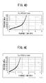
- FIGS. 4A to 4E are graphs which show the relationship of pressure and time when changing the predetermined feed speed when inserting the piston 42 into the internal chamber IC to V 1 to V 4 . If gradually raising the predetermined feed speed "v" of insertion of the piston 42 into the internal chamber IC to V 1 to V 4 , with the feed speeds V 1 , V 2 , and Vc, in the same way as the schematic view which is shown in FIG. 3A , a graph is obtained where the pressure rises and finally becomes the saturated state, but at the feed speeds V 3 and V 4 over the feed speed Vc, the pressure does not become saturated. It is learned that along with the elapse of time, the pressure P of the internal chamber IC rises until a superhigh pressure level.
- FIG. 5 is an explanatory view for analyzing the relationship between the leakage flow rate and the pressure and shows the state where the piston 42 being inserted inside of the work 1 causes working oil 2 to leak out.
- B is the seat circumferential length (circumferential length of center part of clearance 3)
- L is the seat width (width of region where clearance 3 is formed)
- h is the average clearance amount of the clearance 3
- ⁇ is the viscosity coefficient of the working oil 2
- ⁇ P is the pressure difference of the inlet and outlet of the clearance 3.
- the formula (1) is used as the basis to calculate the working oil viscosity ⁇ at the time of the pressure P in the internal chamber IC.
- the ordinary pressure viscosity ⁇ 0 and viscosity-pressure coefficient ⁇ are unambiguously determined by the type of the working oil 2 which is used.
- the "ether-based oil 3" is working oil which is comprised of a polyoxyethylene polyoxypropylene alkyl ether.
- formula 2 is used as the basis to calculate the leakage flow rate Q from the clearance 3 at the time of a certain pressure P of the internal chamber IC.
- the seat circumferential length B and average clearance amount "h" are unambiguously determined from the product shape.
- the viscosity coefficient ⁇ the value found by the above (1) is used.
- the maximum leakage flow rate Qmax which was calculated at (3) is divided by the cross-sectional area A of the piston 42 to calculate the critical feed speed Vc.
- the leakage flow rate of the working oil 2 which flows out from the clearance 3 per unit time is equal to the volume per unit time of the piston 42 which is inserted inside of the work 1, so when the maximum leakage flow rate Qmax is reached, the feed speed of the piston 42 becomes the fastest speed, that is, the critical feed speed Vc.
- FIG. 7 is a graph which shows the relationship of the pressure of the internal chamber IC and the leakage flow rate when changing the average clearance amount "h” of the clearance 3.
- a peak value that is, the maximum leakage flow rate Qmax, occurs in the process of change of the pressure, so in the same way as above, it is sufficient to calculate the critical feed speed Vc corresponding to the individual average clearance amounts.
- FIG. 8 is a graph which shows the relationship between the pressure of the internal chamber IC and the leakage flow rate when changing the type of the working oil and the average clearance amount.
- the type of the working oil a triester-based oil, ether-based oil 1, ether-based oil 5, and monoester-based oil are illustrated.
- the "ether-based oil 1" is a working oil which is comprised of polyethyleneglycol
- the "ether-based oil 5" is a working oil which is comprised of a polyoxypropylene dialkyl ether.
- a peak value that is, the maximum leakage flow rate Qmax, occurs in the process of change of the pressure.
- direct pressurization type autofrettage by finding the maximum leakage flow rate Qmax from the characteristics of the working oil used (working oil viscosity ⁇ ) and the specifications of the clearance 3 between the work 1 and the piston 42 (average clearance amount "h", seat width L, and seat circumferential length B) and using the maximum leakage flow rate Qmax and the specifications of the piston 42 (cross-sectional area A) as the basis to calculate the critical feed speed Vc, if driving the piston 42 by a speed faster than that critical feed speed Vc, it is possible to raise the pressure to the target pressure which is required for autofrettage (as one example, 700 MPa to 800 MPa). Due to this, direct pressurization type autofrettage enables seal rings to be eliminated and enables the increase in cost due to wear of the seal rings to be reduced.
- Direct pressurization type autofrettage solves the problems of autofrettage of the prior art, but various restrictions arise due to feed speed limit of the pressurizing part for pressurizing the autofrettage working oil, the product shape, etc.
- the feed speed "v” has to be limited to about 70% of the normal maximum output. In this way, due to the various restrictions which arise due to the drive motor, pressure control circuit, etc., there is an upper limit to the feed speed "v", so sometimes the feed speed v cannot be raised to the critical feed speed Vc.
- FIG. 9 is a graph which shows the waveform of pressure rise when changing the seat width L of the clearance 3 from “a” to "b".
- FIG. 10 is one example of a fuel injector which is used in a diesel engine.
- FIGS. 11A and 11B are cross-sectional views which show examples of members which are used for fuel injectors.
- the case where the worked object is a fuel injector which is used in a diesel engine (as one example, see Japanese Unexamined Patent Publication No. 2009-203843 etc.) will be explained.
- This fuel injector has a high pressure side duct 101 to which fuel is supplied from a common rail and a low pressure side duct 102 which returns to the fuel tank the fuel which remains without being injected up until the valve is closed.
- the piston etc. are placed so as to move up and down at the center of the body by an actuator (solenoid or piezoelectric device), so the high pressure duct 101 which performs the autofrettage inevitably ends up becoming off-centered. For this reason, the upper duct 101' of the lower body 103' which is shown in FIG. 11A ends up tilting and becoming relatively short.
- the duct 101" is often relatively short. If the duct for autofrettage is short, sometimes the feed speed of the piston will exceed the critical feed speed Vc and it will not be possible to secure the stroke required for reaching the predetermined pressure.
- the work 1 of FIG. 2 illustrates a common rail, so a plurality of pipe openings 23 are provided for feeding fuel to the fuel injectors of the cylinders. In the work 1 which is shown in FIG.
- autofrettage has to be performed at least at the intersecting hole end X, so the distance from one end side of the work 1 to the intersecting hole end X has to be made longer than the stroke which is required for reaching the desired pressure.
- the distance from one end side of the work 1 to the intersecting hole end X is shorter than the stroke necessary for reaching the predetermined pressure.
- the present invention provides a solution to the various restrictions which arise due to the feed speed limit of the working part, the product shape, etc. explained above.
- FIG. 12 and FIG. 13 are schematic cross-sectional views which explain an embodiment of the present invention.
- the work 1 is a high pressure feed pump
- the work 1 is a fuel injector body 103.
- FIG. 14 is a schematic perspective view which explains one embodiment of the present invention of FIG. 13 .
- the high pressure feed pump 1 of FIG. 12 pumps fuel to the common rail, so is known from Japanese Unexamined Patent Publication No. 2010-229924A etc.
- a discharge valve is screwed, while at the part 12, a suction valve is screwed.
- a plunger is inserted into the IC at the inside of the part 13.
- the outer circumference of the part 13 forms a cylindrical surface and is not formed with a thread.
- a jig which can be attached to and detached from the work 1 is prepared to perform the autofrettage. Inside of the jig, there is a straight channel 52. The straight channel 52 is communicated with the end opening 14 of the work 1 through the seal part 55. Further, the piston 42 is not inserted into the work. The piston 42 is inserted at the straight channel 52 of the jig 51 by the critical feed speed Vc or more. Due to this, working oil 2 raised to a superhigh pressure can be filled through the communicating hole 55" of the seal member 55' to the internal chamber IC of the work 1.
- the work 1 is a high pressure feed pump
- the work 1 is a fuel injector body 103, but the present embodiment is not limited to these works.
- the work 1 is a high pressure feed pump.
- the work 1 is placed on a not shown base 56 (see FIG. 14 ) by V-blocks etc.
- a seal member 55' is inserted in the end opening 14 of the work 1 (work end opening) and end opening 52' of the straight channel 52 (connecting end opening which is rounded or chamfered etc.) for sealing.
- the seal member 55' is provided with a communicating hole 55''.
- FIGS. 15A to 15C are modifications of the seal member 55'.
- FIG. 15A shows the above-mentioned ball seal
- FIG. 15B shows a bi-cone
- FIG. 15C shows a cylindrical shape which is rounded at its top and bottom faces.
- the seal member 55' may be made of not only copper or other ordinary seal metal, but also a plastic so long as being satisfactory in mechanical strength. Urethane, a fluororesin, chloroprene, and nitrile are suitable. Ethylene, butyl, etc. may also be used.
- a plastic may be used as the method for selective use of a metal and plastic. If a part where scratching would not pose a problem (part which is chamfered at inside circumference of end opening 14 of work 1 of FIG. 12 etc.), a metal is OK. Further, even with a metal seal, there is no problem if later removing the indented parts of the work which arise due to the seal member 55' at the time of sealing after the autofrettage is finished.
- the jig 51 When inserting the piston 42 into the straight channel 52, air is entrained, so the jig 51 is provided with an air bleed passage which is communicated with the straight channel 52. Further, the air bleed passage 53 is provided with an air bleed passage stop plug 54 so that working oil will not leak at the autofrettage. Note that, this stop plug 54 does not necessarily have to be provided at the jig 51. For example, it is also possible to provide a feed pipe which communicates with the air bleed passage 53 at the opening of the air bleed passage 53, provide a valve in the middle of that feed pipe, and use this valve to open and close the feed pipe. Further, as shown in FIG. 12 , even if the stroke of the internal chamber IC is insufficient and the stroke can no longer be secured at the work 1, the jig 51 enables the stroke to be secured.
- the work 1 is a fuel injector body 103.
- the fuel injector body 103 is placed on the base 56 by V-blocks etc.
- a seal member 55' is used to seal the end opening of the internal chamber IC of the fuel injector body 103 and the end opening of the straight channel 52.
- the seal member 55' must not have seal leakage, so the jig 51 is fastened to the fuel injector body 103 by screwing long bolts 57 at four locations or so of the base 56.
- the outlet of the high pressure duct 101 is sealed by a seal ball 20 by a screw cap 21. The result is similar to the case of FIG. 12 .
- the jig 51 can be used to increase the diameter of the straight channel 52, so the problem of the strength due to the diameter of the piston 42 can be solved.
- FIGS. 16A to 16E are cross-sectional views which show other modifications of the seal part 55.
- the seal member 55' was used to form the seal part 55.
- the seal part 55 need not use the seal member 55'.
- FIG. 16A it is also possible to directly join the end opening face of the work 1 and the end opening face of the jig 51 to form the seal part 55. In this case, it is necessary to make the machining precision of the end opening faces of the work 1 and the jig 51 a good one.
- an O-ring 49 is used to form the seal part 55.
- this is effective when a large space can be taken at the end opening face of the work 1 and the end opening face of the jig 51.
- the tapers or rounded parts which are provided at the work end opening 14 and the connecting end opening 52' do not particularly have to be provided.
- the seal part 55 can also be configured as shown in FIG. 16C .
- the piston 42 If making the piston 42 smaller in diameter, a problem arises in the strength of the piston, so if the diameter of the internal chamber IC becomes too small such as in FIG. 13 , the piston cannot be inserted into the internal chamber IC. However, in such a case as well, if using the jig 51, the diameter of the straight channel 52 of the jig can be made larger, so the problem in strength due to the diameter of the piston 42 can be solved.
Landscapes
- Engineering & Computer Science (AREA)
- Mechanical Engineering (AREA)
- Chemical & Material Sciences (AREA)
- Combustion & Propulsion (AREA)
- General Engineering & Computer Science (AREA)
- Manufacturing & Machinery (AREA)
- Fuel-Injection Apparatus (AREA)
- Shaping Metal By Deep-Drawing, Or The Like (AREA)
Abstract
Description
- The present invention, for example, relates to an autofrettage apparatus which is used for a machine for forming a high pressure fuel injection pipe or a common rail etc., in particular one operating under a superhigh pressure.
- As seen in
PLTs PLT 1 discloses a process which directly inserts a piston of a pressurizing cylinder inside a work so as to raise the pressure. In this process, due to the shape of the work covered by the process (fine bore, short ducts, etc.), various restrictions arose such as an insufficient stroke at the time of raising the pressure or the inability of the piston to be inserted into the work. -
- PLT 1. German Patent No.
102006054440 (DE102006054440B3 ) - PLT 2. Japanese Unexamined Patent Publication No.
2004-92551A - The present invention was made in consideration of the above problem and provides a solution to the various restrictions which arise due to the product shape etc.
- To solve the above problem, the aspect of the invention of
claim 1 provides an autofrettage apparatus comprising a work (1) having a work end opening (14) and internal chamber (IC), wherein the internal chamber (IC) is closed except at the work end opening (14) and working oil (2) is filled from the work end opening (14) to the internal chamber (IC); a jig (51) which can be attached to or detached from the work (1) and has a straight channel (52) at its inside, the straight channel (52) being configured so as to communicate with the work end opening (14) without leakage through a seal part (55); a piston (42) which forms a clearance (3) which has a predetermined average clearance amount (h) with respect to an inside wall of the straight channel (52) which is provided at the inside of the jig; and a pressurizing part (40) which drives the piston (42), wherein the pressurizing part (40) drives the piston (42) so that the piston (42) becomes a predetermined feed speed (v) in the straight channel (52) which is filled by the working oil (2), and the predetermined feed speed (v) is made faster than a critical feed speed (Vc) which corresponds to the maximum leakage flow rate (Qmax) per unit time of the working oil (2) which leaks out from the clearance (3) due to the drive operation, whereby the work (1) is autofrettaged. - Due to this, rather than insert the piston in the work, it is possible to insert the piston in the straight channel of the jig by the critical feed speed Vc or more. Further, by inserting the piston in the jig, it is possible to fill superhigh pressure working oil through the seal part to the internal chamber IC of the
work 1. Therefore, even when there are various restrictions due to the feed speed limit, product shape of the work, etc., it is possible to freely design the conditions necessary for autofrettage (later explained seat width L and seat circumferential length B) at the jig which can be attached to and detached from the work. That is, by using the jig, even if there are various restrictions, the critical feed speed Vc can be suitably set. Further, it is possible to slash costs by reducing the size of the facility and streamlining the work process (slashing the cycle time etc.) - The aspect of the invention of
claim 2 comprises the aspect of the invention ofclaim 1 characterized in that the jig (51) is provided with an air bleed passage (53) which communicates with the straight channel (52). Due to this, it is possible to facilitate bleed of air at the initial filling of working oil. - The aspect of the invention of
claim 3 comprises the aspect of the invention ofclaim 2 characterized in that the air bleed passage (53) is provided with an air bleed passage stop plug (54). - The aspect of the invention of
claim 4 comprises the aspect of the invention of any one ofclaims 1 to 3 characterized in that the seal part (55) seals by pressing a seal member (55') with a communication hole (55") which runs between a work end opening (14) of the work (1) and a connecting end opening (52') of a straight channel (52) of the jig (51) without clearance. Due to this, it is possible to make the seal between the work and the jig perfect. - The aspect of the invention of
claim 5 comprises the aspect of the invention ofclaim 4 characterized in that the seal member (55') is formed by a metal or plastic. - The aspect of the invention of
claim 6 comprises the aspect of the invention of any one ofclaims 1 to 3 characterized in that the seal part (55) seals by pressing together or connecting a work end opening (14) of the work (1) and a connecting end opening (52') of a straight channel (52) of the jig (51) without clearance. Due to this, the seal between the work and the jig can be made perfect. - The aspect of the invention of claim 7 comprises the aspect of the invention of
claim 6 characterized in that either or both of the work end opening (14) of the work (1) or the connecting end opening (52') of the straight channel (52) of the jig (51) are provided with O-rings, ring-shaped projections, tapered surfaces, and threads. Due to this, the seal between the work and the jig can be made perfect. - Note that the above reference notations show examples of the correspondence with the specific examples of the embodiments described later.
-
-
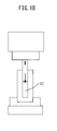
FIG. 1A is an explanatory view which schematically shows a direct pressurization type autofrettage apparatus and which shows the state before apiston 42 starts to slide. -
FIG. 1B is an explanatory view which schematically shows the direct pressurization type autofrettage apparatus and which shows the state after thepiston 42 starts to slide. -
FIG. 2 is an explanatory view which schematically shows the direct pressurization type autofrettage apparatus. -
FIG. 3A is a schematic view which shows a relationship of pressure and time in the apparatus which is shown in -
FIGS. 1A and1B when inserting a piston by a certain feed speed V0 into an internal chamber IC to try to make a pressure P of the internal chamber IC rise. -
FIG. 3B is an explanatory view which explains the state ofFIG. 3A . -
FIG. 4A is a graph which shows a waveform of pressure rise when making a feed speed of insertion of a piston into an internal chamber IC V1. -
FIG. 4B is a graph which shows a waveform of pressure rise when making a feed speed of insertion of a piston into an internal chamber IC V2. -
FIG. 4C is a graph which shows a waveform of pressure rise when making a feed speed of insertion of a piston into an internal chamber IC Vc. -
FIG. 4D is a graph which shows a waveform of pressure rise when making a feed speed of insertion of a piston into an internal chamber IC V3. -
FIG. 4E is a graph which shows a waveform of pressure rise when making a feed speed of insertion of a piston into an internal chamber IC V4. -
FIG. 5 is an explanatory view for analyzing a relationship between leakage and pressure. -
FIG. 6 is an explanatory view for explaining one example of finding a critical feed speed Vc. -
FIG. 7 is a graph which shows a relationship between pressure and leakage flow rate and the critical feed speed Vc when changing an average clearance amount "h". -
FIG. 8 is a graph which shows a relationship between an internal chamber pressure and a maximum leakage flow rate Qmax and average clearance amount "h" when changing a working oil. -
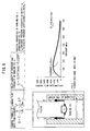
FIG. 9 is a graph which shows a waveform of pressure rise when changing a seat width L of aclearance 3 from "a" to "b". -
FIG. 10 shows one example of a fuel injector which is used in a diesel engine. -
FIG. 11A is a cross-sectional view which shows an example of a member which is used for the fuel injector. -
FIG. 11B is a cross-sectional view which shows an example of a member which is used for the fuel injector. -
FIG. 12 is a schematic perspective view which explains an embodiment of the present invention. -
FIG. 13 is a schematic perspective view which explains an embodiment of the present invention. -
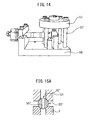
FIG. 14 is a schematic perspective view which explains an embodiment of the present invention ofFIG. 13 . -
FIG. 15A is a cross-sectional view which shows an example of a seal member 55'. -
FIG. 15B is a cross-sectional view which shows a modification of a seal member 55'. -
FIG. 15C is a cross-sectional view which shows a modification of a seal member 55'. -
FIG. 16A is a cross-sectional view which shows a modification of a seal part. -
FIG. 16B is a cross-sectional view which shows a modification of a seal part. -
FIG. 16C is a cross-sectional view which shows a modification of a seal part. -
FIG. 16D is a cross-sectional view which shows a modification of a seal part. -
FIG. 16E is a cross-sectional view which shows a modification of a seal part. - The present invention will be more clearly understood if considering the description of the embodiments of the present invention as explained below with reference to the attached drawings. Below, referring to the drawings, embodiments of the present invention will be explained. In the embodiments, parts of the same configuration will be assigned the same reference notations and explanations will be omitted. The embodiments of the present invention assign the same reference notations to the parts of the same configuration as the basic art forming the foundation of the present invention and omit explanations thereof.
- Direct Pressurization Type Autofrettage Before explaining an embodiment of the present invention, first, the basic art which forms the foundation of the present invention, that is, a direct pressurization type autofrettage apparatus, will be explained. Note that the embodiments of the present invention are predicated on a direct pressurization type autofrettage apparatus.
FIGS. 1A ,1B , and2 are explanatory views which schematically show direct pressurization type autofrettage. As examples of a work 10 which is autofrettaged under a high pressure, in particular parts of a diesel common rail system and other parts where a high fatigue strength limit is required may be mentioned. In addition, the present invention can be applied to a part which requires that residual compression be given for the purpose of increasing the fatigue strength. In the following explanation, the embodiments of the present invention will be explained with reference to examples of the case of autofrettage of awork 1 constituted by a high pressure fuel injector, a rail for common rail use, a cylinder pump, etc. - In
FIGS. 1A and1B , the inside of thework 1 which is shown schematically as a sealed work is filled with workingoil 2. At a pressurizingpart 40 which has a servo motor (drive motor), apiston 42 is connected. Note that the pressurizingpart 40 does not necessarily have to be connected with thepiston 42. Thispiston 42, as shown inFIG. 2 , is inserted so as to have aclearance 3 comprised of an average clearance amount "h" (as one example, 1 to 30 µm) with respect to the inside walls of one end part of thework 1. For this reason, to enable the average clearance amount "h" to be maintained even if thepiston 42 is inserted, the pressurizingpart 40 and thework 1 are fixed to the facility so that the axial direction of the inside of thework 1 at least in the range where thepiston 42 is inserted, the axial direction of thepiston 42, and the pressurizing axial direction of the pressurizingpart 40 match. - Further,
pipe openings 23 of thework 1 are sealed in a state with a sealingmember 24 inserted and with a pressure W applied, while the other end of thework 1 is sealed by aseal pin 4, so thework 1 becomes a structure which is sealed except for at the above one end. Due to thepiston 42, the inside of thework 1 is formed with an internal chamber IC. Further, to measure the pressure P of the internal chamber IC of thework 1, thepiston 42 has astrain gauge 50 attached to it. The pressure P of the internal chamber IC is calculated from the amount of deformation of thepiston 42. Note that as the servo motor which is included at the pressurizingpart 40, a fluid pressure actuator (oil pressure actuator) may also be utilized. Further, an electric motor may be used to turn a screw for pressurization. - Next, the operation in the above configuration will be explained. The other end side of the
work 1 is sealed by theseal pin 4, the sealingmember 24 is inserted in thepipe openings 23 of thework 1, and pressure W is applied to seal it. In that state, workingoil 2 is filled in thework 1. Next, thepiston 42 is inserted from one end side of thework 1 and the noninsertion side of thepiston 42 is connected to the pressurizingpart 40. Here, thepiston 42, as explained above, is set so as to have aclearance 3 which is comprised of a predetermined average clearance amount "h" with respect to one end part of thework 1. No seal rings etc. at all are used between thepiston 42 and the inside walls of thework 1. - In this state, if using the pressurizing
part 40 to insert thepiston 42 in thework 1 at a predetermined feed speed "v", workingoil 2 will leak out from theclearance 3 between the inside walls of thework 1 and thepiston 42, but by setting the above predetermined feed speed "v" to be faster than that leakage speed, that is, inserting thepiston 42 inside of thework 1 by a speed of at least the speed by which workingoil 2 leaks out from theclearance 3, the workingoil 2 which is filled at the inside of thework 1 is compressed and the pressure inside of thework 1 is made to rise. - By doing this, in the autofrettage apparatus, it is possible to perform autofrettage without using seal rings and possible to greatly reduce part consumption due to wear. Further, in the past, if the inside pressure caused deformation to occur, the clearance could not be reduced to zero, so the pressurizing part of the working oil had to be extremely thick and a giant housing was required. By eliminating this giant, expensive housing of the pressurizing part, it is possible to simplify and slim down the structure of the facility and possible to perform autofrettage by a low expense and depreciation.
- Next, the predetermined feed speed "v" when inserting the above-mentioned
piston 42 into thework 1 will be explained and what the critical feed speed Vc and maximum leakage flow rate Qmax per unit time are will be explained. A viscosity η of the workingoil 2 which is filled at the inside of thework 1 can be expressed by the followingformula 1 when designating the pressure of the oil as "P":
- As will be understood from this
formula 1, if the pressure P rises, the viscosity η will exponentially increase. That is, if making thepiston 42 descend at a high speed and making the pressure P of the internal chamber IC of thework 1 rise, this will act to make the inside workingoil 2 rise in viscosity and the leakage flow rate from theclearance 3 to be reduced. It was believed that due to this action, the internal chamber IC would rise in pressure and that the targeted pressure (high pressure performing frettage) could be reached. However, in actuality, something not predicted above was found by in-depth research of the inventors. Below, the content of this will be explained. -
FIG. 3A is a schematic view for explaining a relationship between pressure and time in the autofrettage apparatus which is shown inFIGS. 1A and1B when inserting thepiston 42 in the internal chamber IC by a certain feed speed v=V0 to raise the pressure P of the internal chamber IC, whileFIG. 3B is an explanatory view which explains this situation. As shown inFIG. 3A , regardless of the previous assumptions, even if inserting thepiston 42 by a predetermined feed speed V0 into the internal chamber IC, the pressure P of the internal chamber IC rises up to P2 up to the time T2, but after that the pressure P no longer rises but ends up being saturated and therefore, it was learned, the target pressure (high pressure for performing frettage) cannot be reached. - This situation will be explained as follows using
FIG. 3B . Along with the descent of thepiston 42, the volume of the internal chamber IC decreases and simultaneously workingoil 2 starts to flow out from theclearance 3. There is a time lag between the descent of thepiston 42 and the outflow of the workingoil 2, so the pressure P of the internal chamber IC rises (times T1 to T2). When finally the outflow of the working oil 2 (leakage flow rate) increases, the speed by which the volume of the internal chamber IC decreases also falls until the steady state is reached, so the pressure P of the internal chamber IC becomes saturated (times T2 to T3). In the end, if thepiston 24 stops (time T3), it is believed that the situation arises where the workingoil 2 just flows out and pressure becomes 0 (time T4). - Next, a relationship between pressure and time when changing the constant feed speed "v" will be explained.
FIGS. 4A to 4E are graphs which show the relationship of pressure and time when changing the predetermined feed speed when inserting thepiston 42 into the internal chamber IC to V1 to V4. If gradually raising the predetermined feed speed "v" of insertion of thepiston 42 into the internal chamber IC to V1 to V4, with the feed speeds V1, V2, and Vc, in the same way as the schematic view which is shown inFIG. 3A , a graph is obtained where the pressure rises and finally becomes the saturated state, but at the feed speeds V3 and V4 over the feed speed Vc, the pressure does not become saturated. It is learned that along with the elapse of time, the pressure P of the internal chamber IC rises until a superhigh pressure level. - That is, in the autofrettage apparatus which is shown in
FIGS. 1A and1B , when thepiston 42 is inserted by a certain feed speed into the internal chamber IC to try to make the pressure P of the internal chamber IC rise, if the feed speed "v" of thepiston 42 becomes larger than the feed speed Vc (critical feed speed), the pressure P of the internal chamber IC can be made to rise to a superhigh pressure level along with the elapse of time without becoming saturated. In this way, the feed speed when shifting to a characteristic whereby the pressure P of the internal chamber IC rises to the superhigh pressure level along with the elapse of time without the pressure P becoming saturated is set as the critical feed speed Vc. - Next, the method of finding the above critical feed speed Vc will be explained by an example. Note that the method of finding the critical feed speed Vc may be determined by experiments.
FIG. 5 is an explanatory view for analyzing the relationship between the leakage flow rate and the pressure and shows the state where thepiston 42 being inserted inside of thework 1causes working oil 2 to leak out. The leakage flow rate Q from the clearance 3 (average clearance amount "h") can be expressed by the following general formula:
Here, B is the seat circumferential length (circumferential length of center part of clearance 3), L is the seat width (width of region whereclearance 3 is formed), "h" is the average clearance amount of theclearance 3, η is the viscosity coefficient of the workingoil 2, and ΔP is the pressure difference of the inlet and outlet of theclearance 3. C is a constant which is determined by the surface shape between the piston and the work inside walls. At the time of a polished surface with a surface roughness Rz=3.2 or so, C=1. - The formula (1) is used as the basis to calculate the working oil viscosity η at the time of the pressure P in the internal chamber IC. At this time, the ordinary pressure viscosity η0 and viscosity-pressure coefficient α are unambiguously determined by the type of the working
oil 2 which is used. In the example which is shown inFIG. 6 , an ether-basedoil 3 which has characteristics of an ordinary pressure viscosity η0=0.047 (Pa·s) and a viscosity-pressure coefficient α=10.328 (Pa-1) is used as the workingoil 2. Here, the "ether-basedoil 3" is working oil which is comprised of a polyoxyethylene polyoxypropylene alkyl ether. - (2) After this,
formula 2 is used as the basis to calculate the leakage flow rate Q from theclearance 3 at the time of a certain pressure P of the internal chamber IC. At this time, the seat circumferential length B and average clearance amount "h" are unambiguously determined from the product shape. For the viscosity coefficient η, the value found by the above (1) is used. Note that the seat width L is a variable parameter which inherently increases along with the amount of insertion of the piston, but according to research findings of the inventors, the leakage flow rate Q may be calculated based on a fixed value of the seat width L without problem. In the example which is shown inFIG. 6 , B=9.5 (mm), h=20 (µm), and L=10 (mm). - (3) Between the
inside pressure 0 to 800 MPa or so, the above (1) and (2) are performed, the magnitude of the leakage flow rate Q at each pressure is found, and the largest leakage flow rate Qmax among them (called the "maximum leakage flow rate") is found. - (4) After this, the maximum leakage flow rate Qmax which was calculated at (3) is divided by the cross-sectional area A of the
piston 42 to calculate the critical feed speed Vc. The leakage flow rate of the workingoil 2 which flows out from theclearance 3 per unit time is equal to the volume per unit time of thepiston 42 which is inserted inside of thework 1, so when the maximum leakage flow rate Qmax is reached, the feed speed of thepiston 42 becomes the fastest speed, that is, the critical feed speed Vc. - The critical feed speed VC and the maximum leakage flow rate Qmax are defined in this way. Their relationship can be expressed as follows:
- (Critical feed speed Vc)=(maximum leakage flow rate Qmax)/(cross-sectional area A of piston 42) ···
formula 3 In the case of the example which is shown inFIG. 6 , the maximum leakage flow rate Qmax is 2329.32 (mm3/sec) and the cross-sectional area A of thepiston 42 is 70.8 mm2, so the critical feed speed Vc becomes 32.9 (mm/sec). - That is, if inserting the
piston 42 inside thework 1 by a speed over this critical feed speed Vc=32.9 (mm/sec), as shown inFIG. 4D and FIG. 4E , it becomes possible to make the pressure P of the internal chamber IC rise up to the superhigh pressure level along with the elapse of time without becoming saturated. - Next, the case of changing the average clearance amount "h" of the
clearance 3 while using the same working oil as the workingoil 2 which is shown inFIG. 6 will be explained.FIG. 7 is a graph which shows the relationship of the pressure of the internal chamber IC and the leakage flow rate when changing the average clearance amount "h" of theclearance 3. As shown inFIG. 7 , even if changing the average clearance amount "h" of theclearance 3, in the graph, a peak value, that is, the maximum leakage flow rate Qmax, occurs in the process of change of the pressure, so in the same way as above, it is sufficient to calculate the critical feed speed Vc corresponding to the individual average clearance amounts. Next, the case of using a working oil different from the workingoil 2 which is shown inFIG. 6 while changing the average clearance amount "h" of theclearance 3 will be explained. -
FIG. 8 is a graph which shows the relationship between the pressure of the internal chamber IC and the leakage flow rate when changing the type of the working oil and the average clearance amount. As the type of the working oil, a triester-based oil, ether-basedoil 1, ether-basedoil 5, and monoester-based oil are illustrated. Here, the "ether-basedoil 1" is a working oil which is comprised of polyethyleneglycol, while the "ether-basedoil 5" is a working oil which is comprised of a polyoxypropylene dialkyl ether. As shown inFIG. 8 , even if using as the working oil the above working oils which are different from that shown inFIG. 6 and even if changing the average clearance amount "h" of theclearance 3 by the above working oil, it is learned that, in the graph, a peak value, that is, the maximum leakage flow rate Qmax, occurs in the process of change of the pressure. - According to the above explained direct pressurization type autofrettage, by finding the maximum leakage flow rate Qmax from the characteristics of the working oil used (working oil viscosity η) and the specifications of the
clearance 3 between thework 1 and the piston 42 (average clearance amount "h", seat width L, and seat circumferential length B) and using the maximum leakage flow rate Qmax and the specifications of the piston 42 (cross-sectional area A) as the basis to calculate the critical feed speed Vc, if driving thepiston 42 by a speed faster than that critical feed speed Vc, it is possible to raise the pressure to the target pressure which is required for autofrettage (as one example, 700 MPa to 800 MPa). Due to this, direct pressurization type autofrettage enables seal rings to be eliminated and enables the increase in cost due to wear of the seal rings to be reduced. - Direct pressurization type autofrettage, as explained above, solves the problems of autofrettage of the prior art, but various restrictions arise due to feed speed limit of the pressurizing part for pressurizing the autofrettage working oil, the product shape, etc.
- One is for example the insufficient output of the drive motor for driving the pressurizing
part 40 or the suitable output limit as seen from the lifetime. Due to these factors, the feed speed "v" sometimes cannot rise to the critical feed speed Vc. Further, in the control circuit for controlling the drive motor or the pressure control device for the autofrettage (for example, pressure control of for how many seconds to apply a predetermined pressure or more), if the object to be controlled is just too fast, the restriction will arise that the control circuit and/or device cannot perform control suitably. For this reason, utilizing a certain extent of slower speed facilitates control. The feed speed "v" has to be limited to about 70% of the normal maximum output. In this way, due to the various restrictions which arise due to the drive motor, pressure control circuit, etc., there is an upper limit to the feed speed "v", so sometimes the feed speed v cannot be raised to the critical feed speed Vc. - As one of the measures for dealing with the limit feed speed due to the drive motor or its control device, there is the following. If explaining this as an example, when performing direct pressurization type autofrettage in the state where the seat width L=a and by a first critical feed speed Vca or more, due to the various restrictions which arise due to the drive motor, pressure control circuit, etc., sometimes the feed speed "v" cannot be raised to the first critical feed speed Vca. That is, if referring to the maximum feed speed in the restrictions the "limit feed speed V0", this is the case where V0<Vca.
- In this case, if just able to make the seat width L of the piston a value "b" which is longer than "a", it is possible to perform direct pressurization type autofrettage by a feed speed "v" larger than the second critical feed speed Vcb. The first critical feed speed Vca and second critical feed speed Vcb are respectively determined by
formulas -
FIG. 9 is a graph which shows the waveform of pressure rise when changing the seat width L of theclearance 3 from "a" to "b". The waveform of pressure rise when changing the seat width L of theclearance 3 from a=10 mm to b=20 mm clearly shows that autofrettage becomes possible. The critical feed speed Vca=32.9 mm/sec in the case of a=10 mm falls to the critical feed speed Vcb=16.5 mm/sec in the case of b=20 mm. If making the seat width L of the piston a value "b" which is longer than "a" in this way, it is possible to make the predetermined feed speed "v" faster than the second critical feed speed Vcb and set it to a suitable value less than the limit feed speed V0. However, depending on thework 1, due to the product shape etc., sometimes the seat width L of the piston will not be able to be made the value "b" which is longer than "a". - Further, when performing direct pressurization type autofrettage, the following restriction (example of case of short stroke) will sometimes occur due to the shape of the work to be worked:
FIG. 10 is one example of a fuel injector which is used in a diesel engine.FIGS. 11A and11B are cross-sectional views which show examples of members which are used for fuel injectors. The case where the worked object is a fuel injector which is used in a diesel engine (as one example, see Japanese Unexamined Patent Publication No.2009-203843 pressure side duct 101 to which fuel is supplied from a common rail and a lowpressure side duct 102 which returns to the fuel tank the fuel which remains without being injected up until the valve is closed. As shown inFIG. 10 , at thelarge diameter part 104 at the inside of the fuel injector body 103 (seeFIGS. 11A and11B ), the piston etc. are placed so as to move up and down at the center of the body by an actuator (solenoid or piezoelectric device), so thehigh pressure duct 101 which performs the autofrettage inevitably ends up becoming off-centered. For this reason, the upper duct 101' of the lower body 103' which is shown inFIG. 11A ends up tilting and becoming relatively short. Further, even in the case such as shown inFIG. 11B , theduct 101" is often relatively short. If the duct for autofrettage is short, sometimes the feed speed of the piston will exceed the critical feed speed Vc and it will not be possible to secure the stroke required for reaching the predetermined pressure. - Further, the case where the worked object is a part of a common rail system for a diesel engine will be explained. The fuel which is discharged from the fuel pump is supplied to the common rail under pressure. The common rail stores the fuel which was pumped from the fuel pump at a high pressure state and supplies it to the fuel injectors of the cylinders through high pressure ducts. The
work 1 ofFIG. 2 illustrates a common rail, so a plurality ofpipe openings 23 are provided for feeding fuel to the fuel injectors of the cylinders. In thework 1 which is shown inFIG. 2 , autofrettage has to be performed at least at the intersecting hole end X, so the distance from one end side of thework 1 to the intersecting hole end X has to be made longer than the stroke which is required for reaching the desired pressure. However, depending on the shape of thework 1, sometimes the distance from one end side of thework 1 to the intersecting hole end X is shorter than the stroke necessary for reaching the predetermined pressure. - In this way, there are various restrictions in direct pressurization type autofrettage which inserts a
piston 42 into the inside walls of one end part of thework 1. If again summarizing these restrictions, the following may be illustrated. - (1) Case where due to capacity of pressurizing part, predetermined feed speed of piston cannot be accelerated.
- (2) Case where due to capacity of pressurizing part, pushing pressure of piston cannot be secured, for example, case where internal chamber IC of work is too large in inside diameter and load on pressurizing part is too large.
- (3) Case where due to work shape, stroke cannot be secured.
- (4) Case where due to work shape, diameter of inserted piston is too small and problem arises in strength of inserted piston, that is, diameter of internal chamber IC of the work is too small and the piston cannot be inserted.
- The present invention provides a solution to the various restrictions which arise due to the feed speed limit of the working part, the product shape, etc. explained above.
-
FIG. 12 andFIG. 13 are schematic cross-sectional views which explain an embodiment of the present invention. InFIG. 12 , thework 1 is a high pressure feed pump, while inFIG. 13 , thework 1 is afuel injector body 103.FIG. 14 is a schematic perspective view which explains one embodiment of the present invention ofFIG. 13 . Note that, the highpressure feed pump 1 ofFIG. 12 pumps fuel to the common rail, so is known from Japanese Unexamined Patent Publication No.2010-229924A part 11 ofFIG. 12 , a discharge valve is screwed, while at thepart 12, a suction valve is screwed. A plunger is inserted into the IC at the inside of thepart 13. The outer circumference of thepart 13 forms a cylindrical surface and is not formed with a thread. - First, the outline of one embodiment of the present invention will be explained. In one embodiment of the present invention, when there are the above such various restrictions on the
work 1 for autofrettage, a jig which can be attached to and detached from thework 1 is prepared to perform the autofrettage. Inside of the jig, there is astraight channel 52. Thestraight channel 52 is communicated with the end opening 14 of thework 1 through theseal part 55. Further, thepiston 42 is not inserted into the work. Thepiston 42 is inserted at thestraight channel 52 of thejig 51 by the critical feed speed Vc or more. Due to this, workingoil 2 raised to a superhigh pressure can be filled through the communicatinghole 55" of the seal member 55' to the internal chamber IC of thework 1. - By doing this, even when there are various restrictions due to the feed speed limit, product shape of the work, etc., it is possible to freely design the seat width L and seat circumferential length B as seen in
formula 2 at thejig 51 which can be attached to and detached from thework 1 and the critical feed speed Vc can be suitably set. - That is, regarding the previously illustrated restrictions (1) and (3), even if the seat width L or stroke cannot be secured at the
work 1, it is sufficient to secure the seat width L or stroke at thejig 51. Regarding (2), even if the inside diameter of the internal chamber ID of the work is too large (cross-sectional area is large) and the load on the pressurizing part is too great, it is possible to reduce the diameter of thestraight channel 52 of the jig 51 (cross-sectional area is small), so it is possible to lighten the load of the motor of the pressurizing part. Regarding (4), even if the inside diameter of the internal chamber IC of the work is too small, the diameter of the insertedpiston 42 is small, and a problem arises in strength, the diameter of thestraight channel 52 of thejig 51 can be enlarged, so the problem of the strength due to the diameter of thepiston 42 can be solved. - Below, referring to
FIGS. 12 and13 , one embodiment of the present invention will be explained. InFIG. 12 , thework 1 is a high pressure feed pump, while inFIG. 13 , thework 1 is afuel injector body 103, but the present embodiment is not limited to these works. InFIG. 12 , thework 1 is a high pressure feed pump. Thework 1 is placed on a not shown base 56 (seeFIG. 14 ) by V-blocks etc. A seal member 55' is inserted in the end opening 14 of the work 1 (work end opening) and end opening 52' of the straight channel 52 (connecting end opening which is rounded or chamfered etc.) for sealing. To enable workingoil 2 to be sent into the internal chamber IC, the seal member 55' is provided with a communicating hole 55''. When utilizing chamfering of the inside circumferential surface of the end opening 14 of thework 1 etc., even if deformation of the work occurs due to the seal part, no problem arises in the final product, so this is convenient. - The seal member 55' must not allow seal leakage between the
work 1 and thejig 51, so thejig 51 is fastened to the work by screwing inlong bolts 57 at four locations of thebase 56.FIGS. 15A to 15C are modifications of the seal member 55'.FIG. 15A shows the above-mentioned ball seal,FIG. 15B shows a bi-cone, andFIG. 15C shows a cylindrical shape which is rounded at its top and bottom faces. These are mere examples. The invention is not limited to these. Various modifications are possible. The point is that the seal member 55' be designed to a configuration enabling sealing matching the shapes of the end openings of thework 1 and thejig 51. - The seal member 55' may be made of not only copper or other ordinary seal metal, but also a plastic so long as being satisfactory in mechanical strength. Urethane, a fluororesin, chloroprene, and nitrile are suitable. Ethylene, butyl, etc. may also be used. As the method for selective use of a metal and plastic, when not desiring to scratch the
work 1, that is, when it is essential that the seal surface and properties not be damaged when completing the product, a plastic may be used. If a part where scratching would not pose a problem (part which is chamfered at inside circumference of end opening 14 ofwork 1 ofFIG. 12 etc.), a metal is OK. Further, even with a metal seal, there is no problem if later removing the indented parts of the work which arise due to the seal member 55' at the time of sealing after the autofrettage is finished. - When inserting the
piston 42 into thestraight channel 52, air is entrained, so thejig 51 is provided with an air bleed passage which is communicated with thestraight channel 52. Further, theair bleed passage 53 is provided with an air bleed passage stop plug 54 so that working oil will not leak at the autofrettage. Note that, this stop plug 54 does not necessarily have to be provided at thejig 51. For example, it is also possible to provide a feed pipe which communicates with theair bleed passage 53 at the opening of theair bleed passage 53, provide a valve in the middle of that feed pipe, and use this valve to open and close the feed pipe. Further, as shown inFIG. 12 , even if the stroke of the internal chamber IC is insufficient and the stroke can no longer be secured at thework 1, thejig 51 enables the stroke to be secured. - In
FIG. 13 , thework 1 is afuel injector body 103. As shown inFIG. 14 , thefuel injector body 103 is placed on thebase 56 by V-blocks etc. A seal member 55' is used to seal the end opening of the internal chamber IC of thefuel injector body 103 and the end opening of thestraight channel 52. The seal member 55' must not have seal leakage, so thejig 51 is fastened to thefuel injector body 103 by screwinglong bolts 57 at four locations or so of thebase 56. The outlet of thehigh pressure duct 101 is sealed by aseal ball 20 by ascrew cap 21. The result is similar to the case ofFIG. 12 . - If assuming the case of
FIG. 13 to be the case where the internal chamber IC is too small in diameter and the piston cannot be inserted, thejig 51 can be used to increase the diameter of thestraight channel 52, so the problem of the strength due to the diameter of thepiston 42 can be solved. -
FIGS. 16A to 16E are cross-sectional views which show other modifications of theseal part 55. InFIGS. 12 and13 , the seal member 55' was used to form theseal part 55. Theseal part 55 need not use the seal member 55'. As shown inFIG. 16A , it is also possible to directly join the end opening face of thework 1 and the end opening face of thejig 51 to form theseal part 55. In this case, it is necessary to make the machining precision of the end opening faces of thework 1 and the jig 51 a good one. In this case as well, there must be no seal leakage between thework 1 and thejig 51, so thejig 51 is fastened to the work by screwinglong bolts 57 at four locations or so of thebase 56. Depending on the case, to prevent seal leakage, it is possible to somewhat raise the fastening torque of thelong bolts 57 or increase the bolt diameter. - In
FIG. 16B , an O-ring 49 is used to form theseal part 55. In the case ofFIGS. 16A and16B , this is effective when a large space can be taken at the end opening face of thework 1 and the end opening face of thejig 51. Further, in the case ofFIGS. 16A and16B , the tapers or rounded parts which are provided at thework end opening 14 and the connecting end opening 52' do not particularly have to be provided. When there is a taper at thework 1 as the final product, theseal part 55 can also be configured as shown inFIG. 16C . When desiring to raise the contact pressure at the edges and improve the sealing performance, as shown inFIG. 16D , it is also possible to form a ring-shaped V-cross-section projection 59. When there is an O-ring insertion groove or other circular ring-shaped groove at the end opening face of thework 1, it is possible to utilize this and provide a circular ring-shaped projecting part 59' at the end opening face of thejig 51 so as to form theseal part 55. As seen in thefuel injector body 103 ofFIG. 13 , when there is a thread at the product end (sealing portion by threaded part and threaded cap 21), it is possible to provide a female thread or male thread to configure theseal part 55 so as to enable sealing with thejig 51. - As explained above, even if there are various restrictions due to the product shape etc., if preparing a jig which can be attached to a
work 1 and applying autofrettage, the following various advantageous effects can be obtained. Regardless of the work shape, so long as using thestraight channel 52 of thejig 51, the seat width L and seat circumferential length B and other specifications can be freely designed and the critical feed speed Vc can be suitably set. It is also possible to jointly use a jig for a plurality of products (works). It is also possible to make a jig common for a fuel injector, cylinder pump, etc. Due to this, the manufacturing cost of thejig 51 can be reduced. - If making the
piston 42 smaller in diameter, a problem arises in the strength of the piston, so if the diameter of the internal chamber IC becomes too small such as inFIG. 13 , the piston cannot be inserted into the internal chamber IC. However, in such a case as well, if using thejig 51, the diameter of thestraight channel 52 of the jig can be made larger, so the problem in strength due to the diameter of thepiston 42 can be solved. As opposed to this, if the inside diameter of the internal chamber IC of the work becomes too large (that is, the cross-sectional area becomes large), even if the load on the pressurizing part is too large, the diameter of thestraight channel 52 of thejig 51 can be reduced (that is, the cross-sectional area becomes small), so the load of the motor of the pressurizing part, that is, the necessary load can be reduced. For this reason, it is possible to make the pressurizing part a small sized press machine, so the facility can be reduced in size. - When inserting the
piston 42 into the internal chamber IC of thework 1, troublesome centering and positioning work were required, but due to thejig 51, it is sufficient to perform just the work of theseal part 55, so the work becomes simple, there is no longer a need for a positioning unit, and the cycle time can be slashed. Due to this, it is possible to obtain the advantageous effects of cost reduction and suppression of overall investment (four units being enough despite five being necessary). The present invention was described with reference to specific embodiments which were selected for the purpose of illustration, but it is clear that a person skilled in the art could make numerous modification without departing from the basic concept of the present invention and its scope of disclosure. -
- 1
- work
- 2
- working oil
- 3
- clearance
- 14
- work end opening
- 40
- pressurizing part
- 42
- piston
- 51
- jig
- 52
- straight channel
- 52'
- connecting end opening
- 53
- air bleed passage
Claims (7)
- An autofrettage apparatus comprising,
a work (1) having a work end opening (14) and internal chamber (IC), wherein said internal chamber (IC) is closed except at said work end opening (14) and working oil (2) is filled from said work end opening (14) to said internal chamber (IC);
a jig (51) which can be attached to or detached from said work (1) and has a straight channel (52) at its inside, said straight channel (52) being configured so as to communicate with said work end opening (14) without leakage through a seal part (55);
a piston (42) which forms a clearance (3) which has a predetermined average clearance amount (h) with respect to an inside wall of said straight channel (52) which is provided at the inside of said jig; and
a pressurizing part (40) which drives said piston (42),
wherein said pressurizing part (40) drives said piston (42) so that said piston (42) becomes a predetermined feed speed (v) in said straight channel (52) which is filled by said working oil (2), and
said predetermined feed speed (v) is made faster than a critical feed speed (Vc) which corresponds to the maximum leakage flow rate (Qmax) per unit time of said working oil (2) which leaks out from said clearance (3) due to said drive operation, whereby said work (1) is autofrettaged. - The autofrettage apparatus according to claim 1, characterized in that said jig (51) is provided with an air bleed passage (53) which communicates with said straight channel (52).
- The autofrettage apparatus according to claim 2, characterized in that aid air bleed passage (53) is provided with an air bleed passage stop plug (54).
- The autofrettage apparatus according to any one of claims 1 to 3, characterized in that said seal part (55) seals by pressing a seal member (55') with a communication hole (55") which runs between a work end opening (14) of said work (1) and a connecting end opening (52') of a straight channel (52) of said jig (51) without clearance.
- The autofrettage apparatus according to claim 4, characterized in that said seal member (55') is formed by a metal or plastic.
- The autofrettage apparatus according to any one of claims 1 to 3, characterized in that said seal part (55) seals by pressing together or connecting a work end opening (14) of said work (1) and a connecting end opening (52') of a straight channel (52) of said jig (51) without clearance.
- The autofrettage apparatus according to claim 6, characterized in that either or both of the work end opening (14) of said work (1) or the connecting end opening (52') of the straight channel (52) of said jig (51) are provided with O-rings, ring-shaped projections, tapered surfaces, and threads.
Applications Claiming Priority (2)
| Application Number | Priority Date | Filing Date | Title |
|---|---|---|---|
| JP2011266063A JP5527312B2 (en) | 2011-12-05 | 2011-12-05 | Auto fretage processing equipment |
| PCT/JP2012/068117 WO2013084533A1 (en) | 2011-12-05 | 2012-07-17 | Autofrettage machining device |
Publications (4)
| Publication Number | Publication Date |
|---|---|
| EP2789409A1 true EP2789409A1 (en) | 2014-10-15 |
| EP2789409A4 EP2789409A4 (en) | 2015-07-22 |
| EP2789409B1 EP2789409B1 (en) | 2016-05-04 |
| EP2789409B8 EP2789409B8 (en) | 2016-08-10 |
Family
ID=48573918
Family Applications (1)
| Application Number | Title | Priority Date | Filing Date |
|---|---|---|---|
| EP12854910.2A Not-in-force EP2789409B8 (en) | 2011-12-05 | 2012-07-17 | Autofrettage machining device |
Country Status (4)
| Country | Link |
|---|---|
| EP (1) | EP2789409B8 (en) |
| JP (1) | JP5527312B2 (en) |
| CN (1) | CN103958085B (en) |
| WO (1) | WO2013084533A1 (en) |
Cited By (1)
| Publication number | Priority date | Publication date | Assignee | Title |
|---|---|---|---|---|
| GB2579722A (en) * | 2018-12-04 | 2020-07-01 | Caterpillar Inc | Fuel injector having residually stressed solenoid housing for improved pressure capability |
Families Citing this family (5)
| Publication number | Priority date | Publication date | Assignee | Title |
|---|---|---|---|---|
| WO2016097469A1 (en) * | 2014-12-15 | 2016-06-23 | Wärtsilä Finland Oy | Method of producing a cylinder head for an internal combustion piston engine, a cylinder head blank and a cylinder head of an internal combustion piston engine |
| JP6816592B2 (en) * | 2017-03-22 | 2021-01-20 | 株式会社デンソー | Auto fleetage processing equipment and auto fleshage processing method |
| CN113134991B (en) * | 2021-04-08 | 2023-06-02 | 太原科技大学 | Temperature isostatic pressing machine |
| CN113477779B (en) * | 2021-07-13 | 2023-06-27 | 保隆沙士基达(安徽)液压成型有限公司 | Water injection rod assembly |
| CN114231716B (en) * | 2021-12-28 | 2024-11-05 | 浙江奥加汽车零部件制造有限公司 | Inner wall strengthening device |
Family Cites Families (12)
| Publication number | Priority date | Publication date | Assignee | Title |
|---|---|---|---|---|
| JPS58210359A (en) * | 1982-06-01 | 1983-12-07 | Yanmar Diesel Engine Co Ltd | Connecting structure of high-pressure fuel pipe for fuel injection valve |
| US5282574A (en) * | 1991-12-19 | 1994-02-01 | Caterpillar Inc. | Hydraulic flow shutoff device for a unit fuel pump/injector |
| JP3749013B2 (en) * | 1997-03-03 | 2006-02-22 | 臼井国際産業株式会社 | Common rail and manufacturing method thereof |
| JP4405102B2 (en) * | 2001-04-11 | 2010-01-27 | 臼井国際産業株式会社 | Common rail for diesel engines |
| JP2004092551A (en) | 2002-09-02 | 2004-03-25 | Usui Kokusai Sangyo Kaisha Ltd | Diesel common rail for engine |
| DE102006054440B3 (en) | 2006-11-16 | 2007-12-13 | Maximator Gmbh | Autofrettage method for a fuel injection system of a diesel engine comprises reducing the volume for the fluid using a displacement plunger displaced by a plunger opening of a workpiece in the inner chamber of the workpiece |
| JP4333796B2 (en) * | 2007-01-31 | 2009-09-16 | 株式会社デンソー | Fuel injection pump |
| JP4380739B2 (en) * | 2007-07-06 | 2009-12-09 | 株式会社デンソー | High pressure fuel pump |
| JP5534495B2 (en) * | 2007-08-26 | 2014-07-02 | 臼井国際産業株式会社 | Sealing method in pressure resistance inspection including auto-frettage treatment of high-pressure fuel injection pipe |
| JP4998325B2 (en) | 2008-02-27 | 2012-08-15 | 株式会社デンソー | Filter abnormality determination device for fuel injection valve and fuel injection system |
| JP5187255B2 (en) | 2009-03-27 | 2013-04-24 | 株式会社デンソー | High pressure pump |
| DE102011001763B4 (en) * | 2010-04-07 | 2017-12-21 | Denso Corporation | Autofrettage system, Autofrettageverfahren and method for producing a workpiece by means of Autofrettage |
-
2011
- 2011-12-05 JP JP2011266063A patent/JP5527312B2/en not_active Expired - Fee Related
-
2012
- 2012-07-17 WO PCT/JP2012/068117 patent/WO2013084533A1/en not_active Ceased
- 2012-07-17 EP EP12854910.2A patent/EP2789409B8/en not_active Not-in-force
- 2012-07-17 CN CN201280059826.4A patent/CN103958085B/en not_active Expired - Fee Related
Cited By (3)
| Publication number | Priority date | Publication date | Assignee | Title |
|---|---|---|---|---|
| GB2579722A (en) * | 2018-12-04 | 2020-07-01 | Caterpillar Inc | Fuel injector having residually stressed solenoid housing for improved pressure capability |
| US11105304B2 (en) | 2018-12-04 | 2021-08-31 | Caterpillar Inc. | Fuel injector having residually stressed solenoid housing for improved pressure capapility |
| GB2579722B (en) * | 2018-12-04 | 2022-08-31 | Caterpillar Inc | Fuel injector having residually stressed solenoid housing for improved pressure capability |
Also Published As
| Publication number | Publication date |
|---|---|
| EP2789409A4 (en) | 2015-07-22 |
| WO2013084533A1 (en) | 2013-06-13 |
| CN103958085A (en) | 2014-07-30 |
| CN103958085B (en) | 2015-09-16 |
| EP2789409B8 (en) | 2016-08-10 |
| JP2013116498A (en) | 2013-06-13 |
| EP2789409B1 (en) | 2016-05-04 |
| JP5527312B2 (en) | 2014-06-18 |
Similar Documents
| Publication | Publication Date | Title |
|---|---|---|
| EP2789409B1 (en) | Autofrettage machining device | |
| US20180298894A1 (en) | Valve seat for reciprocating pump | |
| US20210381504A1 (en) | Well service valve seat removal | |
| US8511218B2 (en) | Clamping device for cylinder sleeves and use thereof, and mud pump having a clamping | |
| CN105181475B (en) | A kind of impulse test system of servo electric jar supercharging | |
| CN105980830B (en) | Hydraulic test method and device | |
| CN104169579A (en) | Pump fluid cylinder including load transfer shoulder and valve seat for same | |
| EP2504577B1 (en) | Piston pump | |
| JP2025032109A (en) | Lubricator pump unit and valve seat modification for improving the lubrication system of a large low-speed two-stroke engine, and improved lubricator pump unit | |
| CN108425821B (en) | Hydraulic booster pump | |
| CN211116859U (en) | Hydraulic power pressurization control system of pressure testing machine | |
| CN102321792B (en) | Self-stress processing system, self-stress processing method and method of using self-stress processing production workpiece | |
| JP2010181191A (en) | Internal pressure test device | |
| MX2021004892A (en) | Hydraulic unit with combined pneumatic/servomotor action and related use. | |
| US5927178A (en) | Press driven tool actuator module | |
| US11298737B2 (en) | Device and method for the autofrettage of a workpiece | |
| JP5067468B2 (en) | Auto-frettage processing apparatus, auto-frettage processing method, and method of manufacturing a workpiece subjected to auto-frettage processing | |
| JP5472432B2 (en) | Auto-frettage processing apparatus, auto-frettage processing method, and method of manufacturing a workpiece subjected to auto-frettage processing | |
| TW201704662A (en) | Seals separated by retaining clip | |
| JP2012087356A (en) | Autofrettage processing device, autofrettage processing method, and method for manufacturing workpiece to autofrettage processing | |
| KR20160120300A (en) | Fuel pump | |
| Abhilash et al. | Design, analysis and fabrication of a hydraulic die ejector for a powder metallurgy component | |
| KR102739878B1 (en) | the improved pressing cylinder with stepwise stroke changing | |
| CN206488030U (en) | A kind of grease injector continuously refueled | |
| Gearing et al. | Hydroforming systems, equipment, controls and tooling |
Legal Events
| Date | Code | Title | Description |
|---|---|---|---|
| PUAI | Public reference made under article 153(3) epc to a published international application that has entered the european phase |
Free format text: ORIGINAL CODE: 0009012 |
|
| 17P | Request for examination filed |
Effective date: 20140404 |
|
| AK | Designated contracting states |
Kind code of ref document: A1 Designated state(s): AL AT BE BG CH CY CZ DE DK EE ES FI FR GB GR HR HU IE IS IT LI LT LU LV MC MK MT NL NO PL PT RO RS SE SI SK SM TR |
|
| DAX | Request for extension of the european patent (deleted) | ||
| RA4 | Supplementary search report drawn up and despatched (corrected) |
Effective date: 20150624 |
|
| RIC1 | Information provided on ipc code assigned before grant |
Ipc: B21D 26/033 20110101AFI20150618BHEP Ipc: B23P 9/00 20060101ALI20150618BHEP Ipc: C21D 7/12 20060101ALI20150618BHEP Ipc: F02M 61/16 20060101ALI20150618BHEP Ipc: F02M 55/02 20060101ALI20150618BHEP |
|
| GRAP | Despatch of communication of intention to grant a patent |
Free format text: ORIGINAL CODE: EPIDOSNIGR1 |
|
| RIC1 | Information provided on ipc code assigned before grant |
Ipc: F02M 55/02 20060101ALI20151028BHEP Ipc: B21D 26/033 20110101AFI20151028BHEP Ipc: F02M 61/16 20060101ALI20151028BHEP Ipc: B23P 9/00 20060101ALI20151028BHEP Ipc: C21D 7/12 20060101ALI20151028BHEP Ipc: F02M 55/00 20060101ALI20151028BHEP |
|
| INTG | Intention to grant announced |
Effective date: 20151120 |
|
| GRAS | Grant fee paid |
Free format text: ORIGINAL CODE: EPIDOSNIGR3 |
|
| GRAA | (expected) grant |
Free format text: ORIGINAL CODE: 0009210 |
|
| AK | Designated contracting states |
Kind code of ref document: B1 Designated state(s): AL AT BE BG CH CY CZ DE DK EE ES FI FR GB GR HR HU IE IS IT LI LT LU LV MC MK MT NL NO PL PT RO RS SE SI SK SM TR |
|
| REG | Reference to a national code |
Ref country code: GB Ref legal event code: FG4D |
|
| REG | Reference to a national code |
Ref country code: CH Ref legal event code: EP |
|
| REG | Reference to a national code |
Ref country code: AT Ref legal event code: REF Ref document number: 796441 Country of ref document: AT Kind code of ref document: T Effective date: 20160515 |
|
| REG | Reference to a national code |
Ref country code: IE Ref legal event code: FG4D |
|
| REG | Reference to a national code |
Ref country code: DE Ref legal event code: R096 Ref document number: 602012018206 Country of ref document: DE |
|
| RAP2 | Party data changed (patent owner data changed or rights of a patent transferred) |
Owner name: DENSO CORPORATION |
|
| REG | Reference to a national code |
Ref country code: FR Ref legal event code: PLFP Year of fee payment: 5 |
|
| REG | Reference to a national code |
Ref country code: NL Ref legal event code: MP Effective date: 20160504 |
|
| REG | Reference to a national code |
Ref country code: LT Ref legal event code: MG4D |
|
| PG25 | Lapsed in a contracting state [announced via postgrant information from national office to epo] |
Ref country code: NL Free format text: LAPSE BECAUSE OF FAILURE TO SUBMIT A TRANSLATION OF THE DESCRIPTION OR TO PAY THE FEE WITHIN THE PRESCRIBED TIME-LIMIT Effective date: 20160504 Ref country code: LT Free format text: LAPSE BECAUSE OF FAILURE TO SUBMIT A TRANSLATION OF THE DESCRIPTION OR TO PAY THE FEE WITHIN THE PRESCRIBED TIME-LIMIT Effective date: 20160504 Ref country code: NO Free format text: LAPSE BECAUSE OF FAILURE TO SUBMIT A TRANSLATION OF THE DESCRIPTION OR TO PAY THE FEE WITHIN THE PRESCRIBED TIME-LIMIT Effective date: 20160804 Ref country code: FI Free format text: LAPSE BECAUSE OF FAILURE TO SUBMIT A TRANSLATION OF THE DESCRIPTION OR TO PAY THE FEE WITHIN THE PRESCRIBED TIME-LIMIT Effective date: 20160504 |
|
| REG | Reference to a national code |
Ref country code: AT Ref legal event code: MK05 Ref document number: 796441 Country of ref document: AT Kind code of ref document: T Effective date: 20160504 |
|
| PG25 | Lapsed in a contracting state [announced via postgrant information from national office to epo] |
Ref country code: ES Free format text: LAPSE BECAUSE OF FAILURE TO SUBMIT A TRANSLATION OF THE DESCRIPTION OR TO PAY THE FEE WITHIN THE PRESCRIBED TIME-LIMIT Effective date: 20160504 Ref country code: PT Free format text: LAPSE BECAUSE OF FAILURE TO SUBMIT A TRANSLATION OF THE DESCRIPTION OR TO PAY THE FEE WITHIN THE PRESCRIBED TIME-LIMIT Effective date: 20160905 Ref country code: SE Free format text: LAPSE BECAUSE OF FAILURE TO SUBMIT A TRANSLATION OF THE DESCRIPTION OR TO PAY THE FEE WITHIN THE PRESCRIBED TIME-LIMIT Effective date: 20160504 Ref country code: GR Free format text: LAPSE BECAUSE OF FAILURE TO SUBMIT A TRANSLATION OF THE DESCRIPTION OR TO PAY THE FEE WITHIN THE PRESCRIBED TIME-LIMIT Effective date: 20160805 Ref country code: LV Free format text: LAPSE BECAUSE OF FAILURE TO SUBMIT A TRANSLATION OF THE DESCRIPTION OR TO PAY THE FEE WITHIN THE PRESCRIBED TIME-LIMIT Effective date: 20160504 Ref country code: HR Free format text: LAPSE BECAUSE OF FAILURE TO SUBMIT A TRANSLATION OF THE DESCRIPTION OR TO PAY THE FEE WITHIN THE PRESCRIBED TIME-LIMIT Effective date: 20160504 Ref country code: RS Free format text: LAPSE BECAUSE OF FAILURE TO SUBMIT A TRANSLATION OF THE DESCRIPTION OR TO PAY THE FEE WITHIN THE PRESCRIBED TIME-LIMIT Effective date: 20160504 |
|
| PG25 | Lapsed in a contracting state [announced via postgrant information from national office to epo] |
Ref country code: BE Free format text: LAPSE BECAUSE OF NON-PAYMENT OF DUE FEES Effective date: 20160731 Ref country code: IT Free format text: LAPSE BECAUSE OF FAILURE TO SUBMIT A TRANSLATION OF THE DESCRIPTION OR TO PAY THE FEE WITHIN THE PRESCRIBED TIME-LIMIT Effective date: 20160504 |
|
| PG25 | Lapsed in a contracting state [announced via postgrant information from national office to epo] |
Ref country code: DK Free format text: LAPSE BECAUSE OF FAILURE TO SUBMIT A TRANSLATION OF THE DESCRIPTION OR TO PAY THE FEE WITHIN THE PRESCRIBED TIME-LIMIT Effective date: 20160504 Ref country code: EE Free format text: LAPSE BECAUSE OF FAILURE TO SUBMIT A TRANSLATION OF THE DESCRIPTION OR TO PAY THE FEE WITHIN THE PRESCRIBED TIME-LIMIT Effective date: 20160504 Ref country code: CZ Free format text: LAPSE BECAUSE OF FAILURE TO SUBMIT A TRANSLATION OF THE DESCRIPTION OR TO PAY THE FEE WITHIN THE PRESCRIBED TIME-LIMIT Effective date: 20160504 Ref country code: RO Free format text: LAPSE BECAUSE OF FAILURE TO SUBMIT A TRANSLATION OF THE DESCRIPTION OR TO PAY THE FEE WITHIN THE PRESCRIBED TIME-LIMIT Effective date: 20160504 Ref country code: SK Free format text: LAPSE BECAUSE OF FAILURE TO SUBMIT A TRANSLATION OF THE DESCRIPTION OR TO PAY THE FEE WITHIN THE PRESCRIBED TIME-LIMIT Effective date: 20160504 |
|
| REG | Reference to a national code |
Ref country code: DE Ref legal event code: R097 Ref document number: 602012018206 Country of ref document: DE |
|
| PG25 | Lapsed in a contracting state [announced via postgrant information from national office to epo] |
Ref country code: AT Free format text: LAPSE BECAUSE OF FAILURE TO SUBMIT A TRANSLATION OF THE DESCRIPTION OR TO PAY THE FEE WITHIN THE PRESCRIBED TIME-LIMIT Effective date: 20160504 Ref country code: PL Free format text: LAPSE BECAUSE OF FAILURE TO SUBMIT A TRANSLATION OF THE DESCRIPTION OR TO PAY THE FEE WITHIN THE PRESCRIBED TIME-LIMIT Effective date: 20160504 Ref country code: SM Free format text: LAPSE BECAUSE OF FAILURE TO SUBMIT A TRANSLATION OF THE DESCRIPTION OR TO PAY THE FEE WITHIN THE PRESCRIBED TIME-LIMIT Effective date: 20160504 Ref country code: BE Free format text: LAPSE BECAUSE OF FAILURE TO SUBMIT A TRANSLATION OF THE DESCRIPTION OR TO PAY THE FEE WITHIN THE PRESCRIBED TIME-LIMIT Effective date: 20160504 |
|
| REG | Reference to a national code |
Ref country code: CH Ref legal event code: PL |
|
| PLBE | No opposition filed within time limit |
Free format text: ORIGINAL CODE: 0009261 |
|
| STAA | Information on the status of an ep patent application or granted ep patent |
Free format text: STATUS: NO OPPOSITION FILED WITHIN TIME LIMIT |
|
| PG25 | Lapsed in a contracting state [announced via postgrant information from national office to epo] |
Ref country code: MC Free format text: LAPSE BECAUSE OF FAILURE TO SUBMIT A TRANSLATION OF THE DESCRIPTION OR TO PAY THE FEE WITHIN THE PRESCRIBED TIME-LIMIT Effective date: 20160504 |
|
| 26N | No opposition filed |
Effective date: 20170207 |
|
| GBPC | Gb: european patent ceased through non-payment of renewal fee |
Effective date: 20160804 |
|
| PG25 | Lapsed in a contracting state [announced via postgrant information from national office to epo] |
Ref country code: LI Free format text: LAPSE BECAUSE OF NON-PAYMENT OF DUE FEES Effective date: 20160731 Ref country code: CH Free format text: LAPSE BECAUSE OF NON-PAYMENT OF DUE FEES Effective date: 20160731 |
|
| REG | Reference to a national code |
Ref country code: IE Ref legal event code: MM4A |
|
| PG25 | Lapsed in a contracting state [announced via postgrant information from national office to epo] |
Ref country code: SI Free format text: LAPSE BECAUSE OF FAILURE TO SUBMIT A TRANSLATION OF THE DESCRIPTION OR TO PAY THE FEE WITHIN THE PRESCRIBED TIME-LIMIT Effective date: 20160504 |
|
| REG | Reference to a national code |
Ref country code: FR Ref legal event code: PLFP Year of fee payment: 6 |
|
| PG25 | Lapsed in a contracting state [announced via postgrant information from national office to epo] |
Ref country code: GB Free format text: LAPSE BECAUSE OF NON-PAYMENT OF DUE FEES Effective date: 20160804 Ref country code: IE Free format text: LAPSE BECAUSE OF NON-PAYMENT OF DUE FEES Effective date: 20160717 |
|
| PG25 | Lapsed in a contracting state [announced via postgrant information from national office to epo] |
Ref country code: LU Free format text: LAPSE BECAUSE OF NON-PAYMENT OF DUE FEES Effective date: 20160717 |
|
| PG25 | Lapsed in a contracting state [announced via postgrant information from national office to epo] |
Ref country code: HU Free format text: LAPSE BECAUSE OF FAILURE TO SUBMIT A TRANSLATION OF THE DESCRIPTION OR TO PAY THE FEE WITHIN THE PRESCRIBED TIME-LIMIT; INVALID AB INITIO Effective date: 20120717 |
|
| PG25 | Lapsed in a contracting state [announced via postgrant information from national office to epo] |
Ref country code: CY Free format text: LAPSE BECAUSE OF FAILURE TO SUBMIT A TRANSLATION OF THE DESCRIPTION OR TO PAY THE FEE WITHIN THE PRESCRIBED TIME-LIMIT Effective date: 20160504 Ref country code: MK Free format text: LAPSE BECAUSE OF FAILURE TO SUBMIT A TRANSLATION OF THE DESCRIPTION OR TO PAY THE FEE WITHIN THE PRESCRIBED TIME-LIMIT Effective date: 20160504 Ref country code: MT Free format text: LAPSE BECAUSE OF NON-PAYMENT OF DUE FEES Effective date: 20160731 Ref country code: IS Free format text: LAPSE BECAUSE OF FAILURE TO SUBMIT A TRANSLATION OF THE DESCRIPTION OR TO PAY THE FEE WITHIN THE PRESCRIBED TIME-LIMIT Effective date: 20160504 |
|
| REG | Reference to a national code |
Ref country code: FR Ref legal event code: PLFP Year of fee payment: 7 |
|
| PG25 | Lapsed in a contracting state [announced via postgrant information from national office to epo] |
Ref country code: BG Free format text: LAPSE BECAUSE OF FAILURE TO SUBMIT A TRANSLATION OF THE DESCRIPTION OR TO PAY THE FEE WITHIN THE PRESCRIBED TIME-LIMIT Effective date: 20160504 |
|
| PG25 | Lapsed in a contracting state [announced via postgrant information from national office to epo] |
Ref country code: TR Free format text: LAPSE BECAUSE OF FAILURE TO SUBMIT A TRANSLATION OF THE DESCRIPTION OR TO PAY THE FEE WITHIN THE PRESCRIBED TIME-LIMIT Effective date: 20160504 Ref country code: AL Free format text: LAPSE BECAUSE OF FAILURE TO SUBMIT A TRANSLATION OF THE DESCRIPTION OR TO PAY THE FEE WITHIN THE PRESCRIBED TIME-LIMIT Effective date: 20160504 |
|
| PGFP | Annual fee paid to national office [announced via postgrant information from national office to epo] |
Ref country code: FR Payment date: 20190719 Year of fee payment: 8 Ref country code: DE Payment date: 20190719 Year of fee payment: 8 |
|
| REG | Reference to a national code |
Ref country code: DE Ref legal event code: R119 Ref document number: 602012018206 Country of ref document: DE |
|
| PG25 | Lapsed in a contracting state [announced via postgrant information from national office to epo] |
Ref country code: FR Free format text: LAPSE BECAUSE OF NON-PAYMENT OF DUE FEES Effective date: 20200731 |
|
| PG25 | Lapsed in a contracting state [announced via postgrant information from national office to epo] |
Ref country code: DE Free format text: LAPSE BECAUSE OF NON-PAYMENT OF DUE FEES Effective date: 20210202 |