EP2789394B1 - Verfahrenstechnische Maschine zur Installation in eine Wand - Google Patents
Verfahrenstechnische Maschine zur Installation in eine Wand Download PDFInfo
- Publication number
- EP2789394B1 EP2789394B1 EP14001234.5A EP14001234A EP2789394B1 EP 2789394 B1 EP2789394 B1 EP 2789394B1 EP 14001234 A EP14001234 A EP 14001234A EP 2789394 B1 EP2789394 B1 EP 2789394B1
- Authority
- EP
- European Patent Office
- Prior art keywords
- room
- machines
- mounting plate
- clean room
- accordance
- Prior art date
- Legal status (The legal status is an assumption and is not a legal conclusion. Google has not performed a legal analysis and makes no representation as to the accuracy of the status listed.)
- Active
Links
Images

Classifications
-
- B—PERFORMING OPERATIONS; TRANSPORTING
- B02—CRUSHING, PULVERISING, OR DISINTEGRATING; PREPARATORY TREATMENT OF GRAIN FOR MILLING
- B02C—CRUSHING, PULVERISING, OR DISINTEGRATING IN GENERAL; MILLING GRAIN
- B02C23/00—Auxiliary methods or auxiliary devices or accessories specially adapted for crushing or disintegrating not provided for in preceding groups or not specially adapted to apparatus covered by a single preceding group
- B02C23/04—Safety devices
-
- B—PERFORMING OPERATIONS; TRANSPORTING
- B07—SEPARATING SOLIDS FROM SOLIDS; SORTING
- B07B—SEPARATING SOLIDS FROM SOLIDS BY SIEVING, SCREENING, SIFTING OR BY USING GAS CURRENTS; SEPARATING BY OTHER DRY METHODS APPLICABLE TO BULK MATERIAL, e.g. LOOSE ARTICLES FIT TO BE HANDLED LIKE BULK MATERIAL
- B07B11/00—Arrangement of accessories in apparatus for separating solids from solids using gas currents
-
- B—PERFORMING OPERATIONS; TRANSPORTING
- B08—CLEANING
- B08B—CLEANING IN GENERAL; PREVENTION OF FOULING IN GENERAL
- B08B17/00—Methods preventing fouling
-
- F—MECHANICAL ENGINEERING; LIGHTING; HEATING; WEAPONS; BLASTING
- F16—ENGINEERING ELEMENTS AND UNITS; GENERAL MEASURES FOR PRODUCING AND MAINTAINING EFFECTIVE FUNCTIONING OF MACHINES OR INSTALLATIONS; THERMAL INSULATION IN GENERAL
- F16M—FRAMES, CASINGS OR BEDS OF ENGINES, MACHINES OR APPARATUS, NOT SPECIFIC TO ENGINES, MACHINES OR APPARATUS PROVIDED FOR ELSEWHERE; STANDS; SUPPORTS
- F16M1/00—Frames or casings of engines, machines or apparatus; Frames serving as machinery beds
Definitions
- the invention is directed to a device for installing one or more process engineering machines in an opening of a wall of a room with a holding plate which receives the machines.
- Process engineering machines and apparatuses such as mills are used, inter alia, in the pharmaceutical industry. These machines are used to process highly effective and / or toxic substances. For this purpose, the machines are installed in isolators, so that the operating personnel and the environment do not come into contact with the substances mentioned.
- the clean room in which the product is processed is separated from the engineering area, so that no active substance and no air from the product area are transferred to the technical area and no impurities and substances from the technical area are transferred to the product area. Both areas are part of the insulator.
- mills and other product-contacting components of the machine or system are arranged.
- the drives of the machines, the controls and the cabling, or the drive and control areas are located outside of the insulator as in the EP 1 300 195 A1 disclosed. If the machines used in production exceed a certain size, it will be very expensive and expensive to install them in an isolator. These machines are installed and operated as a whole, ie product area and technical area in a clean room. This means for the operator to adapt the entire machine to the clean room conditions, namely to keep sterile and clean. Due to constructional conditions, an accurate GMP-compliant cleaning, especially of the technical field, can not always be guaranteed or only possible with great effort. The control of GMP-compliant cleaning is not possible. When cleaning these machines, the technical limits are reached.
- the air duct in the clean room as far as technically possible controlled and defined executed.
- the fan of a motor leads to a fault the air flow and creates unwanted, critical and turbulent areas in the clean room, which leads to unwanted Aufwirbelungen but also deposits of product and impurities.
- enclosures are built around the critical areas such as motors and controls, which however increase the required volume of space for these components.
- the drive unit it is then very difficult in the clean room, the drive unit to wait or in the event of a fault to start again. There is always the risk of contamination of the clean room. Troubleshooting and maintenance work are only possible and permissible if the clean room is released and production is therefore interrupted.
- machines are also set up stationary over two separate rooms.
- the DE 103 11 997 A1 describes an invertible filter centrifuge which is constructed in a clean room and a machine room.
- the machine frame is stationary mounted on a support frame and anchored over this in the bottom of the engine room.
- On the machine frame of the process room is connected which protrudes through a building partition in the clean room.
- a flexible gas-tight connection element between the building partition and centrifuge separates the clean room from the machine room.
- the US 4 997 417 A also shows a centrifuge which is installed via sealing elements in an opening of a wall, thus delimiting the machine side of the clean room side. This centrifuge is also stationary.
- the EP 1 118 381 A2 discloses a container with agitator, which is constructed of two half-shells and is installed in the ceiling of a room to separate the production area (clean room) of the machine area. Also, this device is stationary, since it is firmly installed in the ceiling of a room.
- the invention is therefore an object of the invention to provide a solution that allows easy and quick installation and removal of devices in which a structural separation of the product-contacted and to be cleaned components of the machine required by the operation of the machine drive / and Control components is provided.
- the object is achieved by the characterizing part of claim 1.
- the process engineering machines such as mills and rotary valves are constructively built on a device with holding plate that all components required for driving and controlling the machines are separated by one or more holding plates of the product-contacting components of the machines.
- the device with holding plate can be installed in a recess of a wall of a room so that the product-contacted components are arranged in a space and the drive and control components of the machines in a second space, such as the technology area, are arranged.
- the room for the wetted components is a clean room.
- the opening in the wall can be a door, but also a window.
- the drive and control unit is accessible at all times.
- the production does not necessarily have to be interrupted for repair or repair work.
- the clean room does not need to be released for work on the drives and the controller.
- the machines themselves are optimized for the best possible cleaning in terms of gap-free, drainable and much more. They are GMP compliant.
- the technical area can be separated from the clean room by a vertical holding plate, but it can also be arranged below the clean room and thus be separated from the clean room by a horizontal holding plate.
- the holding plate of the device has a circumferential seal on its circumference, which seals the holding plate against the opening in the room wall.
- the seal has a hollow chamber profile.
- the seal is an inflatable seal. It is filled with compressed air and can be so easy and quick sealing, but it can also be easily disabled, so that the device can be easily and quickly installed and rebuilt.
- mills, classifiers, mixers, metering devices, rotary valves or combinations thereof are preferably installed in the holding plate.
- the device is equipped with rollers for movement in space.
- the device may be equipped with transport air cushions which allow extremely easy movement and positioning of the device in the space or in the intended opening in the room wall. In combination with the inflated seal, a simple and precise sealing of clean room and technical area is possible.
- the openings through the retaining plate for the shaft passages of the drives are also dustproof and hermetically sealed, for example by shaft seals, flushing gaps or other static sightings.
- the invention is suitable for supplementing a modular concept. Different types of mill can be exchanged depending on the task in the holding plate, without. For example, to rebuild the dosing device and a downstream air classifier. It is also possible to let the vertical support plate of the device consist of several mutually sealed sections, each receiving a process engineering machine, which is assembled depending on the task and required machine to a holding plate. Again, an inflatable seal is used. It can also be provided several devices with different machines that are used depending on the task in an existing clean room.
Landscapes
- Engineering & Computer Science (AREA)
- General Engineering & Computer Science (AREA)
- Food Science & Technology (AREA)
- Mechanical Engineering (AREA)
- Ventilation (AREA)
- Cage And Drive Apparatuses For Elevators (AREA)
- Cleaning By Liquid Or Steam (AREA)
- Cleaning In General (AREA)
Description
- Die Erfindung richtet sich auf eine Vorrichtung zum Einbauen einer oder mehrerer verfahrenstechnischer Maschinen in eine Öffnung einer Wand eines Raums mit einer Halteplatte die die Maschinen aufnimmt.
- Verfahrenstechnische Maschinen und Apparate wie Mühlen kommen unter anderem in der pharmazeutischen Industrie zum Einsatz. Mit diesen Maschinen werden hoch wirksame und / oder toxische Wirkstoffe verarbeitet. Dazu werden die Maschinen in Isolatoren eingebaut, damit das Bedienpersonal und die Umwelt nicht mit den genannten Stoffen in Kontakt kommen. In diesen Isolatoren ist der Reinraum in dem das Produkt verarbeitet wird vom Technikbereich getrennt, sodass kein Wirkstoff und keine Luft aus dem Produktbereich in den Technikbereich übertreten und keine Verunreinigungen und Stoffe aus dem Technikbereich in den Produktbereich übergehen. Beide Bereiche sind Bestandteil des Isolators. Im Reinraum sind Dosiergeräte, Mühlen und andere produktberührte Komponenten der Maschinen bzw. Anlage angeordnet. Im Technikbereich befinden sich die Antriebe der Maschinen, die Steuerungen und die Verkabelungen, oder die Antriebs- und Steuerungsbereiche befinden sich außerhalb des Isolators wie in der
EP 1 300 195 A1 offenbart. Überschreiten die Maschinen, die in der Produktion zum Einsatz kommen, eine bestimmte Größe wird es sehr aufwendig und kostenintensiv diese in einen Isolator einzubauen. Diese Maschinen werden als Ganzes, d.h. Produktbereich und Technikbereich in einem Reinraum aufgestellt und betrieben. Dies bedeutet für den Betreiber die komplette Maschine an die Reinraumbedingungen anzupassen, nämlich steril zu halten und zu reinigen. Aufgrund von konstruktiven Gegebenheiten ist eine akkurate GMP-gerechte Reinigung, speziell des Technikbereichs, nicht immer zu garantieren bzw. nur mit sehr großem Aufwand möglich. Auch die Kontrolle der GMP-gerechten Reinigung ist nicht möglich. Bei der Reinigung dieser Maschinen werden die technischen Grenzen erreicht. - Üblicherweise wird die Luftführung im Reinraum, soweit technisch möglich kontrolliert und definiert ausgeführt. Beispielsweise führt das Lüfterrad eines Motors zur Störung der Luftströmung und erzeugt ungewollte, kritische und turbulente Bereiche im Reinraum, wodurch es zu ungewollten Aufwirbelungen aber auch Ablagerungen von Produkt und Verunreinigungen kommt.
Alternativ werden Einhausungen um die kritischen Bereiche wie Motore und Steuerungen gebaut, welche aber das benötigte Raumvolumen für diese Komponenten erhöhen. Des Weiteren ist es im Reinraum dann nur sehr erschwert möglich die Antriebseinheit zu warten oder im Falle einer Störung wieder in Gang zu setzen. Es besteht immer die Gefahr einer Kontamination des Reinraums. Beheben von Störungen und Wartungsarbeiten sind nur dann möglich und zulässig, wenn der Reinraum freigegeben ist und die Produktion somit unterbrochen ist.
Alternativ werden Maschinen auch stationär über zwei getrennte Räume aufgebaut. DieDE 103 11 997 A1 beschreibt eine Stülpfilterzentrifuge, die in einem Reinraum und einem Maschinenraum aufgebaut ist. Das Maschinengestell ist stationär auf einem Stützgestell befestigt und über dieses im Boden des Maschinenraums verankert. Am Maschinengestell ist der Verfahrensraum angeschlossen der durch eine Gebäudetrennwand in den Reinraum hineinragt. Ein flexibles gasdichtes Verbindungelement zwischen Gebäudetrennwand und Zentrifuge trennt den Reinraum vom Maschinenraum.
DieUS 4 997 417 A zeigt ebenfalls eine Zentrifuge die über Dichtungselemente in eine Öffnung einer Wand eingebaut ist und so Maschinenseite von Reinraumseite abgrenzt. Auch diese Zentrifuge ist stationär aufgestellt.
DieEP 1 118 381 A2 offenbart einen Behälter mit Rührwerk, der aus zwei Halbschalen aufgebaut ist und in die Decke eines Raumes eingebaut ist, um den Produktionsbereich (Reinraum) von dem Maschinenbereich zu trennen. Auch diese Vorrichtung ist stationär, da sie fest in die Decke des einen Raumes eingebaut ist.
Der Erfindung liegt daher die Aufgabe zugrunde, eine Lösung zu schaffen, die einen einfachen und schnellen Ein- und Ausbau von Vorrichtungen ermöglichen, bei denen eine konstruktive Trennung der produktberührten und zu reinigenden Komponenten der Maschine von den zum Betrieb der Maschine benötigten Antriebs-/ und Steuerungskomponenten vorzusehen ist. - Bei einer verfahrentechnischen Maschine der eingangs beschriebenen Art wird die Aufgabe erfindungsgemäß durch das Kennzeichen das Anspruches 1 gelöst.
Die verfahrenstechnischen Maschinen wie beispielsweise Mühlen und Zellenradschleusen sind konstruktiv so auf eine Vorrichtung mit Halteplatte gebaut, dass alle zum Antreiben und Steuern der Maschinen erforderlichen Komponenten durch eine oder mehrere Halteplatten von den produktberührten Komponenten der Maschinen getrennt sind. Die Vorrichtung mit Halteplatte ist in eine Ausnehmung einer Wand eines Raums so einbaubar, dass die produktberührten Komponenten in einem Raum angeordnet sind und die Antriebs- und Steuerungskomponenten der Maschinen in einem zweiten Raum, z.B. dem Technikbereich, angeordnet sind.
Bei dem Raum für die produktberührten Komponenten handelt es sich um einen Reinraum. Die Öffnung in der Wand kann eine Tür sein, aber auch ein Fenster. - Durch diese konstruktive Gestaltung wird eine Reduktion der zu reinigenden Teile im Reinraum erreicht. Schlecht zu reinigende Bereiche speziell der Antriebstechnik müssen nicht mehr aufwendig gekapselt oder gereinigt werden. Die Antrieb- und Steuereinheit ist jederzeit zugänglich. Die Produktion muss für Reparatur- oder Instandsetzungsarbeiten nicht zwangsweise unterbrochen werden. Der Reinraum braucht für Arbeiten an den Antrieben und der Steuerung nicht freigegeben zu werden.
Die Maschinen selbst sind auf bestmögliche Reinigung hinsichtlich Spaltfreiheit, Entleerbarkeit und vieles mehr optimiert. Sie sind GMP-konform ausgeführt.
Der Technikbereich kann durch eine senkrechte Halteplatte vom Reinraum getrennt sein, er kann aber auch unterhalb des Reinraumes angeordnet sein und so durch eine waagerechte Halteplatte vom Reinraum getrennt sein.
Die Halteplatte der Vorrichtung weist eine an ihrem Umfang umlaufende Dichtung auf, die die Halteplatte gegen die Öffnung in der Raumwand abdichtet. Es wird so der verbleibende Spalt zwischen der Halteplatte und der Ausnehmung in der Raumwand abgedichtet. So sind Reinraum und Technikbereich gas- und staubdicht gegeneinander abgedichtet.
In einer Ausführungsform der Erfindung weist die Dichtung ein Hohlkammerprofil auf. Die Dichtung ist eine aufblasbare Dichtung. Sie wird mit Druckluft gefüllt und kann so einfach und schnell dichtend wirken, sie kann aber auch einfach deaktiviert werden, so dass die Vorrichtung einfach und schnell ein- und umgebaut werden kann. - Bevorzugt werden in weiteren Ausgestaltungen der Erfindung Mühlen, Sichter, Mischer, Dosiereinrichtungen, Zellenradschleusen oder Kombinationen davon in die Halteplatte eingebaut.
Zur weiteren Ausgestaltung der Erfindung ist die Vorrichtung mit Rollen zur Bewegung in Raum ausgestattet. Alternativ kann die Vorrichtung mit Transportluftkissen ausgerüstet sein, die eine extrem einfache Bewegung und Positionierung der Vorrichtung im Raum bzw. in der vorgesehenen Öffnung in der Raumwand ermöglicht. In Kombination mit der aufgeblasenen Dichtung ist eine einfache und präzise Abdichtung von Reinraum und Technikbereich möglich. - Des Weiteren sind die Durchbrüche durch die Halteplatte für die Wellendurchführungen der Antriebe ebenfalls staub- und luftdicht abgeschlossen, beispielsweise durch Wellendichtungen, Spülspalte oder andere statischen Sichtungen.
Die Erfindung ist geeignet um ein Modulkonzept zu ergänzen. Dabei können verschiedene Mühlentypen je nach Aufgabenstellung in der Halteplatte ausgetauscht werden, ohne. z.B. die Dosiervorrichtung und einen nachgeschalteten Windsichter umbauen zu müssen.
Es ist auch möglich die senkrechte Halteplatte der Vorrichtung aus mehreren gegeneinander abgedichteten Abschnitten bestehen zu lassen, die je eine verfahrenstechnische Maschine aufnimmt, die je nach Aufgabenstellung und benötigte Maschine zu einer Halteplatte zusammengestellt wird. Auch hier kommt eine aufblasbare Dichtung zum Einsatz. Es können auch mehrere Vorrichtungen mit unterschiedlichen Maschinen bereitgestellt werden, die je nach Aufgabenstellung in einem vorhandenen Reinraum genutzt werden. - Dieses Prinzip kann auch bei Isolatoren Anwendung finden, wenn ein und der selbe Isolator mit unterschiedlichen Maschinen ausgerüstet werden soll. Es kann dann das gesamte Modul ausgetauscht werden und es müssen nicht die Maschinen und Antriebe aus und andere eingebaut werden.
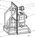
Die Erfindung wird anhand der Figuren im nachfolgenden Ausführungsbeispiel beschrieben. Die Figuren zeigen: -
Figur 1 : Vorrichtung in einer perspektivischen Darstellung -
Figur 2 . Vorrichtung eingebaut in eine Öffnung einer Reinraumwand. - 2 Halteplatte
- 3 Zellenradschleuse
- 4 Sichtermühle
- 5 Motor
- 6 Motor
- 7 Motor
- 8 Aufblasbare Dichtung
- 9 Transportluftkissen
- 10 Arretierbare Füße
- 11 Wandöffnung
- 12 Reinraum
- 13 Technikbereich
In
Die Dichtung (8) ist aufgeblasen und dichtet die Vorrichtung (1) gegen die Wand und den Boden ab, sodass gleichzeitig der Reinraum gegen den Technikbereich gas- und staubdicht abgedichtet ist. Die Dichtung (8) wird mit gereinigter d.h. ölfreier Duckluft befüllt.
Die Durchführungen in der Halteplatte (2) zwischen Prozesskomponente (3, 4) und Antriebsteil (5, 6, 7) sind ebenfalls abgedichtet. Hier kommen entsprechende Dichtungssysteme und Spülspalte zum Einsatz. Die aufblasbare Dichtung (8) besitzt ein Hohlkammerprofil. Sie dichtet über einen breiten Bereich die Halteplatte (2) der Vorrichtung (1) gegen die Füllung der Wandausnehmung (11) ab. Aufgrund der Form der Dichtung wird hier eine Abdichtung gegen Staub und Luft erreicht.
Claims (7)
- Vorrichtung (1) zum Einbauen einer oder mehrerer verfahrenstechnischer Maschinen mit einer Halteplatte (2) für die Maschinen in eine Öffnung (11) einer Wand eines Raums, wobei die Halteplatte (2) eine erste Seite mit den produktberührten Komponenten der Maschinen (3, 4) aufweist und eine zweite Seite mit den Antriebs- (5, 6, 7) und Steuerkomponenten der Maschinen, wobei die Halteplatte (2) an ihrem Umfang eine umlaufende Dichtung (8) aufweist, die die Halteplatte (2) gegen die Wand des Raumes abdichtet, dadurch gekennzeichnet, dass die Dichtung (8) eine aufblasbare Dichtung ist und die Vorrichtung (1) mit Rollen oder Transportluftkissen (10) zur Bewegung und Positionierung im Raum ausgestattet ist.
- Vorrichtung nach Anspruch 1 dadurch gekennzeichnet, dass der Raum ein Reinraum oder Produktionsraum ist und die Wand eine Trennung zwischen Rein- oder Produktionsraum und Technikraum ist.
- Vorrichtung nach Anspruch 1 dadurch gekennzeichnet, dass die produktberührten Komponenten der Maschinen (3, 4) auf der Reinraum- oder Produktionsraumseite der Halteplatte (2) angeordnet sind und die Antriebs- (5, 6, 7) und Steuerungskomponenten an der reinraum- oder produktionsraumabgewandten Seite der Halteplatte (2), einem Technikbereich, angeordnet sind.
- Vorrichtung nach einem oder mehreren der vorangegangenen Ansprüche, dadurch gekennzeichnet, dass die Dichtung (8) gas- und staubdicht ist.
- Vorrichtung nach einem oder mehreren der vorangegangenen Ansprüche, dadurch gekennzeichnet, dass eine der verfahrenstechnischen Maschinen (3, 4) eine Mühle, ein Sichter, ein Mischer, eine Dosiereinheit, eine Zellenradschleuse ist oder Kombinationen daraus sind.
- Vorrichtung nach einem oder mehreren der vorangegangenen Ansprüche, dadurch gekennzeichnet, dass die Durchbrüche in der Halteplatte (2) für die Wellendurchführungen der Maschinen staub- und gasdicht abgedichtet sind.
- Vorrichtung nach einem oder mehreren der vorangegangenen Ansprüche, dadurch gekennzeichnet, dass die Halteplatte (2) aus mehreren gegeneinander abgedichtete Abschnitten besteht die je eine verfahrenstechnische Maschine tragen.
Applications Claiming Priority (1)
| Application Number | Priority Date | Filing Date | Title |
|---|---|---|---|
| DE102013006411.2A DE102013006411B4 (de) | 2013-04-13 | 2013-04-13 | Verfahrenstechnische Maschine zur Installation in eine Wand |
Publications (3)
| Publication Number | Publication Date |
|---|---|
| EP2789394A2 EP2789394A2 (de) | 2014-10-15 |
| EP2789394A3 EP2789394A3 (de) | 2014-12-17 |
| EP2789394B1 true EP2789394B1 (de) | 2018-08-15 |
Family
ID=50542760
Family Applications (1)
| Application Number | Title | Priority Date | Filing Date |
|---|---|---|---|
| EP14001234.5A Active EP2789394B1 (de) | 2013-04-13 | 2014-04-03 | Verfahrenstechnische Maschine zur Installation in eine Wand |
Country Status (2)
| Country | Link |
|---|---|
| EP (1) | EP2789394B1 (de) |
| DE (1) | DE102013006411B4 (de) |
Families Citing this family (2)
| Publication number | Priority date | Publication date | Assignee | Title |
|---|---|---|---|---|
| CN206343269U (zh) * | 2014-12-17 | 2017-07-21 | 菲活机器制造公司 | 用于执行多个破碎和研磨过程的模块化系统 |
| DE102021128897B4 (de) | 2021-05-05 | 2025-01-16 | Aufbereitungstechnologie Noll Gmbh | Anordnung zum Trockenvermahlen und Aufbereiten von unterschiedlichsten Materialien im Feinstkornbereich |
Family Cites Families (5)
| Publication number | Priority date | Publication date | Assignee | Title |
|---|---|---|---|---|
| CH695239C1 (de) * | 2000-01-21 | 2009-11-30 | Rosenmund Vta Ag | Einrichtung zum Behandeln von Stoffen. |
| FR2641715B1 (fr) * | 1989-01-19 | 1991-04-12 | Robatel Slpi | Essoreuse centrifuge a cuve articulee pour filtration en atmosphere sterile |
| EP1300195B1 (de) * | 2000-05-22 | 2007-10-31 | Nara Machinery Co., Ltd. | Pulververarbeitungsanlage |
| DE10311997A1 (de) | 2003-03-19 | 2004-10-07 | Johannes Gerteis | Stülpfilterzentrifuge |
| DE102009019868B4 (de) | 2009-05-06 | 2015-10-22 | Hosokawa Alpine Ag | Verfahrenstechnische Anlage für den Laborbetrieb |
-
2013
- 2013-04-13 DE DE102013006411.2A patent/DE102013006411B4/de active Active
-
2014
- 2014-04-03 EP EP14001234.5A patent/EP2789394B1/de active Active
Non-Patent Citations (1)
| Title |
|---|
| None * |
Also Published As
| Publication number | Publication date |
|---|---|
| DE102013006411A1 (de) | 2014-10-16 |
| EP2789394A2 (de) | 2014-10-15 |
| EP2789394A3 (de) | 2014-12-17 |
| DE102013006411B4 (de) | 2018-10-04 |
Similar Documents
| Publication | Publication Date | Title |
|---|---|---|
| EP4200962B1 (de) | Vorrichtung zur manipulation eines gegenstandes, verfahren zur befüllung eines gegenstandes und korrespondierende verwendung | |
| EP2372749B1 (de) | Behandlungsvorrichtung zur Behandlung einer Oberfläche eines Körpers | |
| EP3062909B1 (de) | Filterwechselvorrichtung und verfahren zu deren betrieb | |
| EP2853849B1 (de) | Trockenraum, insbesondere für den Einsatz bei der Lithium-Ionen-Zellfertigung | |
| EP1710053A2 (de) | Gerät zur Handhabung und/oder Behandlung von Erzeugnissen | |
| EP2177473B1 (de) | Vorrichtung zum Transportieren von Behältnissen | |
| WO2017088075A1 (de) | Filtersystem für ein von einem gasstrom durchflossenes containment | |
| DE10311997A1 (de) | Stülpfilterzentrifuge | |
| DE102013006411B4 (de) | Verfahrenstechnische Maschine zur Installation in eine Wand | |
| DE102014114837A1 (de) | Kältemittelverdichter | |
| WO2010088782A1 (de) | Filtervorrichtung für eine von einem gasstrom durchflossene anlage mit einer arbeitskammer zur temporären aufnahme von behandlungsgut | |
| DE102010004211A1 (de) | Verarbeitungsmaschine bzw. -gerät für Trockeneis | |
| WO1991009793A1 (de) | Einrichtung zum fördern von werkstücken bzw. werkstückträgern | |
| EP3241766B1 (de) | Kammerbandmaschine | |
| DE202010000713U1 (de) | Verarbeitungsmaschine bzw. -gerät für Trockeneis | |
| DE2657558A1 (de) | Vorrichtung zum behandeln von druckplatten | |
| DE102004026883A1 (de) | Anordnung zum sterilen Abfüllen | |
| KR101804302B1 (ko) | 산업용 프레임커버 크리닝 장치 및 크리닝 방법 | |
| EP2666532B2 (de) | Filtereinheit für ein Barrieresystem | |
| DE2363921A1 (de) | Tablettenpresse, insbesondere rundlauf-tablettenpresse | |
| WO2005113169A1 (de) | Verfahren und apparatur für den phasenwechsel in einem isolator | |
| DE102014107063B4 (de) | Behandlungsvorrichtung für Werkteile mit einer elektrischen Behandlungseinheit | |
| WO2014012528A2 (de) | Vorrichtung zum messen der luftdichtheit einer gebäudehülle | |
| WO2005084835A1 (de) | Anordnung zur luftführung und druckregelung in einem isolator mit einer gegen die äussere umgebung abgeschirmten arbeitskammer | |
| EP4265381A1 (de) | Isolatorsystem |
Legal Events
| Date | Code | Title | Description |
|---|---|---|---|
| PUAI | Public reference made under article 153(3) epc to a published international application that has entered the european phase |
Free format text: ORIGINAL CODE: 0009012 |
|
| 17P | Request for examination filed |
Effective date: 20140403 |
|
| AK | Designated contracting states |
Kind code of ref document: A2 Designated state(s): AL AT BE BG CH CY CZ DE DK EE ES FI FR GB GR HR HU IE IS IT LI LT LU LV MC MK MT NL NO PL PT RO RS SE SI SK SM TR |
|
| AX | Request for extension of the european patent |
Extension state: BA ME |
|
| PUAL | Search report despatched |
Free format text: ORIGINAL CODE: 0009013 |
|
| AK | Designated contracting states |
Kind code of ref document: A3 Designated state(s): AL AT BE BG CH CY CZ DE DK EE ES FI FR GB GR HR HU IE IS IT LI LT LU LV MC MK MT NL NO PL PT RO RS SE SI SK SM TR |
|
| AX | Request for extension of the european patent |
Extension state: BA ME |
|
| RIC1 | Information provided on ipc code assigned before grant |
Ipc: B02C 23/04 20060101AFI20141111BHEP Ipc: F16M 1/00 20060101ALI20141111BHEP |
|
| R17P | Request for examination filed (corrected) |
Effective date: 20150601 |
|
| RBV | Designated contracting states (corrected) |
Designated state(s): AL AT BE BG CH CY CZ DE DK EE ES FI FR GB GR HR HU IE IS IT LI LT LU LV MC MK MT NL NO PL PT RO RS SE SI SK SM TR |
|
| GRAP | Despatch of communication of intention to grant a patent |
Free format text: ORIGINAL CODE: EPIDOSNIGR1 |
|
| STAA | Information on the status of an ep patent application or granted ep patent |
Free format text: STATUS: GRANT OF PATENT IS INTENDED |
|
| RIC1 | Information provided on ipc code assigned before grant |
Ipc: B02C 23/04 20060101AFI20180326BHEP Ipc: B08B 17/00 20060101ALI20180326BHEP Ipc: F16M 1/00 20060101ALI20180326BHEP Ipc: B07B 11/00 20060101ALI20180326BHEP |
|
| INTG | Intention to grant announced |
Effective date: 20180420 |
|
| GRAS | Grant fee paid |
Free format text: ORIGINAL CODE: EPIDOSNIGR3 |
|
| GRAA | (expected) grant |
Free format text: ORIGINAL CODE: 0009210 |
|
| STAA | Information on the status of an ep patent application or granted ep patent |
Free format text: STATUS: THE PATENT HAS BEEN GRANTED |
|
| RIN1 | Information on inventor provided before grant (corrected) |
Inventor name: WAGNER, ANTON Inventor name: BORN, OLAF Inventor name: STAHL, JUERGEN |
|
| AK | Designated contracting states |
Kind code of ref document: B1 Designated state(s): AL AT BE BG CH CY CZ DE DK EE ES FI FR GB GR HR HU IE IS IT LI LT LU LV MC MK MT NL NO PL PT RO RS SE SI SK SM TR |
|
| REG | Reference to a national code |
Ref country code: CH Ref legal event code: EP Ref country code: GB Ref legal event code: FG4D Free format text: NOT ENGLISH Ref country code: AT Ref legal event code: REF Ref document number: 1029144 Country of ref document: AT Kind code of ref document: T Effective date: 20180815 |
|
| REG | Reference to a national code |
Ref country code: IE Ref legal event code: FG4D Free format text: LANGUAGE OF EP DOCUMENT: GERMAN |
|
| REG | Reference to a national code |
Ref country code: DE Ref legal event code: R096 Ref document number: 502014009174 Country of ref document: DE |
|
| REG | Reference to a national code |
Ref country code: CH Ref legal event code: NV Representative=s name: SCHMAUDER AND PARTNER AG PATENT- UND MARKENANW, CH |
|
| REG | Reference to a national code |
Ref country code: NL Ref legal event code: MP Effective date: 20180815 |
|
| REG | Reference to a national code |
Ref country code: LT Ref legal event code: MG4D |
|
| PG25 | Lapsed in a contracting state [announced via postgrant information from national office to epo] |
Ref country code: GR Free format text: LAPSE BECAUSE OF FAILURE TO SUBMIT A TRANSLATION OF THE DESCRIPTION OR TO PAY THE FEE WITHIN THE PRESCRIBED TIME-LIMIT Effective date: 20181116 Ref country code: NO Free format text: LAPSE BECAUSE OF FAILURE TO SUBMIT A TRANSLATION OF THE DESCRIPTION OR TO PAY THE FEE WITHIN THE PRESCRIBED TIME-LIMIT Effective date: 20181115 Ref country code: SE Free format text: LAPSE BECAUSE OF FAILURE TO SUBMIT A TRANSLATION OF THE DESCRIPTION OR TO PAY THE FEE WITHIN THE PRESCRIBED TIME-LIMIT Effective date: 20180815 Ref country code: LT Free format text: LAPSE BECAUSE OF FAILURE TO SUBMIT A TRANSLATION OF THE DESCRIPTION OR TO PAY THE FEE WITHIN THE PRESCRIBED TIME-LIMIT Effective date: 20180815 Ref country code: FI Free format text: LAPSE BECAUSE OF FAILURE TO SUBMIT A TRANSLATION OF THE DESCRIPTION OR TO PAY THE FEE WITHIN THE PRESCRIBED TIME-LIMIT Effective date: 20180815 Ref country code: RS Free format text: LAPSE BECAUSE OF FAILURE TO SUBMIT A TRANSLATION OF THE DESCRIPTION OR TO PAY THE FEE WITHIN THE PRESCRIBED TIME-LIMIT Effective date: 20180815 Ref country code: IS Free format text: LAPSE BECAUSE OF FAILURE TO SUBMIT A TRANSLATION OF THE DESCRIPTION OR TO PAY THE FEE WITHIN THE PRESCRIBED TIME-LIMIT Effective date: 20181215 Ref country code: BG Free format text: LAPSE BECAUSE OF FAILURE TO SUBMIT A TRANSLATION OF THE DESCRIPTION OR TO PAY THE FEE WITHIN THE PRESCRIBED TIME-LIMIT Effective date: 20181115 Ref country code: NL Free format text: LAPSE BECAUSE OF FAILURE TO SUBMIT A TRANSLATION OF THE DESCRIPTION OR TO PAY THE FEE WITHIN THE PRESCRIBED TIME-LIMIT Effective date: 20180815 |
|
| PG25 | Lapsed in a contracting state [announced via postgrant information from national office to epo] |
Ref country code: AL Free format text: LAPSE BECAUSE OF FAILURE TO SUBMIT A TRANSLATION OF THE DESCRIPTION OR TO PAY THE FEE WITHIN THE PRESCRIBED TIME-LIMIT Effective date: 20180815 Ref country code: LV Free format text: LAPSE BECAUSE OF FAILURE TO SUBMIT A TRANSLATION OF THE DESCRIPTION OR TO PAY THE FEE WITHIN THE PRESCRIBED TIME-LIMIT Effective date: 20180815 Ref country code: HR Free format text: LAPSE BECAUSE OF FAILURE TO SUBMIT A TRANSLATION OF THE DESCRIPTION OR TO PAY THE FEE WITHIN THE PRESCRIBED TIME-LIMIT Effective date: 20180815 |
|
| PG25 | Lapsed in a contracting state [announced via postgrant information from national office to epo] |
Ref country code: EE Free format text: LAPSE BECAUSE OF FAILURE TO SUBMIT A TRANSLATION OF THE DESCRIPTION OR TO PAY THE FEE WITHIN THE PRESCRIBED TIME-LIMIT Effective date: 20180815 Ref country code: PL Free format text: LAPSE BECAUSE OF FAILURE TO SUBMIT A TRANSLATION OF THE DESCRIPTION OR TO PAY THE FEE WITHIN THE PRESCRIBED TIME-LIMIT Effective date: 20180815 Ref country code: ES Free format text: LAPSE BECAUSE OF FAILURE TO SUBMIT A TRANSLATION OF THE DESCRIPTION OR TO PAY THE FEE WITHIN THE PRESCRIBED TIME-LIMIT Effective date: 20180815 Ref country code: RO Free format text: LAPSE BECAUSE OF FAILURE TO SUBMIT A TRANSLATION OF THE DESCRIPTION OR TO PAY THE FEE WITHIN THE PRESCRIBED TIME-LIMIT Effective date: 20180815 Ref country code: CZ Free format text: LAPSE BECAUSE OF FAILURE TO SUBMIT A TRANSLATION OF THE DESCRIPTION OR TO PAY THE FEE WITHIN THE PRESCRIBED TIME-LIMIT Effective date: 20180815 Ref country code: IT Free format text: LAPSE BECAUSE OF FAILURE TO SUBMIT A TRANSLATION OF THE DESCRIPTION OR TO PAY THE FEE WITHIN THE PRESCRIBED TIME-LIMIT Effective date: 20180815 |
|
| REG | Reference to a national code |
Ref country code: DE Ref legal event code: R097 Ref document number: 502014009174 Country of ref document: DE |
|
| PG25 | Lapsed in a contracting state [announced via postgrant information from national office to epo] |
Ref country code: SM Free format text: LAPSE BECAUSE OF FAILURE TO SUBMIT A TRANSLATION OF THE DESCRIPTION OR TO PAY THE FEE WITHIN THE PRESCRIBED TIME-LIMIT Effective date: 20180815 Ref country code: DK Free format text: LAPSE BECAUSE OF FAILURE TO SUBMIT A TRANSLATION OF THE DESCRIPTION OR TO PAY THE FEE WITHIN THE PRESCRIBED TIME-LIMIT Effective date: 20180815 Ref country code: SK Free format text: LAPSE BECAUSE OF FAILURE TO SUBMIT A TRANSLATION OF THE DESCRIPTION OR TO PAY THE FEE WITHIN THE PRESCRIBED TIME-LIMIT Effective date: 20180815 |
|
| PLBE | No opposition filed within time limit |
Free format text: ORIGINAL CODE: 0009261 |
|
| STAA | Information on the status of an ep patent application or granted ep patent |
Free format text: STATUS: NO OPPOSITION FILED WITHIN TIME LIMIT |
|
| 26N | No opposition filed |
Effective date: 20190516 |
|
| PG25 | Lapsed in a contracting state [announced via postgrant information from national office to epo] |
Ref country code: SI Free format text: LAPSE BECAUSE OF FAILURE TO SUBMIT A TRANSLATION OF THE DESCRIPTION OR TO PAY THE FEE WITHIN THE PRESCRIBED TIME-LIMIT Effective date: 20180815 |
|
| REG | Reference to a national code |
Ref country code: BE Ref legal event code: MM Effective date: 20190430 |
|
| GBPC | Gb: european patent ceased through non-payment of renewal fee |
Effective date: 20190403 |
|
| PG25 | Lapsed in a contracting state [announced via postgrant information from national office to epo] |
Ref country code: LU Free format text: LAPSE BECAUSE OF NON-PAYMENT OF DUE FEES Effective date: 20190403 Ref country code: MC Free format text: LAPSE BECAUSE OF FAILURE TO SUBMIT A TRANSLATION OF THE DESCRIPTION OR TO PAY THE FEE WITHIN THE PRESCRIBED TIME-LIMIT Effective date: 20180815 |
|
| PG25 | Lapsed in a contracting state [announced via postgrant information from national office to epo] |
Ref country code: GB Free format text: LAPSE BECAUSE OF NON-PAYMENT OF DUE FEES Effective date: 20190403 |
|
| PG25 | Lapsed in a contracting state [announced via postgrant information from national office to epo] |
Ref country code: BE Free format text: LAPSE BECAUSE OF NON-PAYMENT OF DUE FEES Effective date: 20190430 Ref country code: FR Free format text: LAPSE BECAUSE OF NON-PAYMENT OF DUE FEES Effective date: 20190430 |
|
| PG25 | Lapsed in a contracting state [announced via postgrant information from national office to epo] |
Ref country code: TR Free format text: LAPSE BECAUSE OF FAILURE TO SUBMIT A TRANSLATION OF THE DESCRIPTION OR TO PAY THE FEE WITHIN THE PRESCRIBED TIME-LIMIT Effective date: 20180815 |
|
| PG25 | Lapsed in a contracting state [announced via postgrant information from national office to epo] |
Ref country code: IE Free format text: LAPSE BECAUSE OF NON-PAYMENT OF DUE FEES Effective date: 20190403 |
|
| PG25 | Lapsed in a contracting state [announced via postgrant information from national office to epo] |
Ref country code: PT Free format text: LAPSE BECAUSE OF FAILURE TO SUBMIT A TRANSLATION OF THE DESCRIPTION OR TO PAY THE FEE WITHIN THE PRESCRIBED TIME-LIMIT Effective date: 20181215 |
|
| PGFP | Annual fee paid to national office [announced via postgrant information from national office to epo] |
Ref country code: DE Payment date: 20200624 Year of fee payment: 7 |
|
| REG | Reference to a national code |
Ref country code: AT Ref legal event code: MM01 Ref document number: 1029144 Country of ref document: AT Kind code of ref document: T Effective date: 20190403 |
|
| PG25 | Lapsed in a contracting state [announced via postgrant information from national office to epo] |
Ref country code: AT Free format text: LAPSE BECAUSE OF NON-PAYMENT OF DUE FEES Effective date: 20190403 |
|
| PG25 | Lapsed in a contracting state [announced via postgrant information from national office to epo] |
Ref country code: CY Free format text: LAPSE BECAUSE OF FAILURE TO SUBMIT A TRANSLATION OF THE DESCRIPTION OR TO PAY THE FEE WITHIN THE PRESCRIBED TIME-LIMIT Effective date: 20180815 |
|
| PG25 | Lapsed in a contracting state [announced via postgrant information from national office to epo] |
Ref country code: MT Free format text: LAPSE BECAUSE OF FAILURE TO SUBMIT A TRANSLATION OF THE DESCRIPTION OR TO PAY THE FEE WITHIN THE PRESCRIBED TIME-LIMIT Effective date: 20180815 Ref country code: HU Free format text: LAPSE BECAUSE OF FAILURE TO SUBMIT A TRANSLATION OF THE DESCRIPTION OR TO PAY THE FEE WITHIN THE PRESCRIBED TIME-LIMIT; INVALID AB INITIO Effective date: 20140403 |
|
| REG | Reference to a national code |
Ref country code: DE Ref legal event code: R119 Ref document number: 502014009174 Country of ref document: DE |
|
| PG25 | Lapsed in a contracting state [announced via postgrant information from national office to epo] |
Ref country code: DE Free format text: LAPSE BECAUSE OF NON-PAYMENT OF DUE FEES Effective date: 20211103 |
|
| PG25 | Lapsed in a contracting state [announced via postgrant information from national office to epo] |
Ref country code: MK Free format text: LAPSE BECAUSE OF FAILURE TO SUBMIT A TRANSLATION OF THE DESCRIPTION OR TO PAY THE FEE WITHIN THE PRESCRIBED TIME-LIMIT Effective date: 20180815 |
|
| P01 | Opt-out of the competence of the unified patent court (upc) registered |
Effective date: 20230515 |
|
| PGFP | Annual fee paid to national office [announced via postgrant information from national office to epo] |
Ref country code: CH Payment date: 20250501 Year of fee payment: 12 |
|
| REG | Reference to a national code |
Ref country code: CH Ref legal event code: U11 Free format text: ST27 STATUS EVENT CODE: U-0-0-U10-U11 (AS PROVIDED BY THE NATIONAL OFFICE) Effective date: 20260501 |