EP2787293A1 - Integriertes Membranentfeuchtungssystem - Google Patents
Integriertes Membranentfeuchtungssystem Download PDFInfo
- Publication number
- EP2787293A1 EP2787293A1 EP20140157538 EP14157538A EP2787293A1 EP 2787293 A1 EP2787293 A1 EP 2787293A1 EP 20140157538 EP20140157538 EP 20140157538 EP 14157538 A EP14157538 A EP 14157538A EP 2787293 A1 EP2787293 A1 EP 2787293A1
- Authority
- EP
- European Patent Office
- Prior art keywords
- contactor
- control device
- heat pump
- hygroscopic material
- air temperature
- Prior art date
- Legal status (The legal status is an assumption and is not a legal conclusion. Google has not performed a legal analysis and makes no representation as to the accuracy of the status listed.)
- Granted
Links
- 239000012528 membrane Substances 0.000 title description 3
- 238000007791 dehumidification Methods 0.000 title description 2
- 239000000463 material Substances 0.000 claims abstract description 55
- 239000003507 refrigerant Substances 0.000 claims abstract description 29
- 238000004891 communication Methods 0.000 claims abstract description 6
- XLYOFNOQVPJJNP-UHFFFAOYSA-N water Chemical compound O XLYOFNOQVPJJNP-UHFFFAOYSA-N 0.000 claims description 18
- 238000012546 transfer Methods 0.000 claims description 12
- 238000005057 refrigeration Methods 0.000 claims description 5
- 239000006096 absorbing agent Substances 0.000 claims description 2
- 238000005498 polishing Methods 0.000 abstract 2
- 239000002274 desiccant Substances 0.000 description 34
- 239000007788 liquid Substances 0.000 description 17
- 238000010586 diagram Methods 0.000 description 9
- 239000012530 fluid Substances 0.000 description 6
- 238000004378 air conditioning Methods 0.000 description 5
- 238000000034 method Methods 0.000 description 5
- 230000008569 process Effects 0.000 description 5
- 238000005516 engineering process Methods 0.000 description 4
- KWGKDLIKAYFUFQ-UHFFFAOYSA-M lithium chloride Chemical compound [Li+].[Cl-] KWGKDLIKAYFUFQ-UHFFFAOYSA-M 0.000 description 4
- 230000008901 benefit Effects 0.000 description 3
- 230000002209 hydrophobic effect Effects 0.000 description 3
- 238000012856 packing Methods 0.000 description 3
- 239000011148 porous material Substances 0.000 description 3
- 239000007787 solid Substances 0.000 description 3
- 230000001143 conditioned effect Effects 0.000 description 2
- 238000005260 corrosion Methods 0.000 description 2
- 230000007797 corrosion Effects 0.000 description 2
- 238000013461 design Methods 0.000 description 2
- 238000011084 recovery Methods 0.000 description 2
- 238000004781 supercooling Methods 0.000 description 2
- 238000011144 upstream manufacturing Methods 0.000 description 2
- 239000003570 air Substances 0.000 description 1
- 230000004075 alteration Effects 0.000 description 1
- 238000007906 compression Methods 0.000 description 1
- 238000009833 condensation Methods 0.000 description 1
- 230000005494 condensation Effects 0.000 description 1
- 238000010276 construction Methods 0.000 description 1
- 230000008878 coupling Effects 0.000 description 1
- 238000010168 coupling process Methods 0.000 description 1
- 238000005859 coupling reaction Methods 0.000 description 1
- 230000007423 decrease Effects 0.000 description 1
- 230000036541 health Effects 0.000 description 1
- 238000010438 heat treatment Methods 0.000 description 1
- 230000010354 integration Effects 0.000 description 1
- 238000012423 maintenance Methods 0.000 description 1
- 239000000203 mixture Substances 0.000 description 1
- 230000008929 regeneration Effects 0.000 description 1
- 238000011069 regeneration method Methods 0.000 description 1
- 238000003303 reheating Methods 0.000 description 1
- 238000000926 separation method Methods 0.000 description 1
- 238000005507 spraying Methods 0.000 description 1
- 238000006467 substitution reaction Methods 0.000 description 1
- 238000009423 ventilation Methods 0.000 description 1
Images




Classifications
-
- F—MECHANICAL ENGINEERING; LIGHTING; HEATING; WEAPONS; BLASTING
- F24—HEATING; RANGES; VENTILATING
- F24F—AIR-CONDITIONING; AIR-HUMIDIFICATION; VENTILATION; USE OF AIR CURRENTS FOR SCREENING
- F24F3/00—Air-conditioning systems in which conditioned primary air is supplied from one or more central stations to distributing units in the rooms or spaces where it may receive secondary treatment; Apparatus specially designed for such systems
- F24F3/12—Air-conditioning systems in which conditioned primary air is supplied from one or more central stations to distributing units in the rooms or spaces where it may receive secondary treatment; Apparatus specially designed for such systems characterised by the treatment of the air otherwise than by heating and cooling
- F24F3/14—Air-conditioning systems in which conditioned primary air is supplied from one or more central stations to distributing units in the rooms or spaces where it may receive secondary treatment; Apparatus specially designed for such systems characterised by the treatment of the air otherwise than by heating and cooling by humidification; by dehumidification
- F24F3/1411—Air-conditioning systems in which conditioned primary air is supplied from one or more central stations to distributing units in the rooms or spaces where it may receive secondary treatment; Apparatus specially designed for such systems characterised by the treatment of the air otherwise than by heating and cooling by humidification; by dehumidification by absorbing or adsorbing water, e.g. using an hygroscopic desiccant
-
- F—MECHANICAL ENGINEERING; LIGHTING; HEATING; WEAPONS; BLASTING
- F24—HEATING; RANGES; VENTILATING
- F24F—AIR-CONDITIONING; AIR-HUMIDIFICATION; VENTILATION; USE OF AIR CURRENTS FOR SCREENING
- F24F3/00—Air-conditioning systems in which conditioned primary air is supplied from one or more central stations to distributing units in the rooms or spaces where it may receive secondary treatment; Apparatus specially designed for such systems
- F24F3/12—Air-conditioning systems in which conditioned primary air is supplied from one or more central stations to distributing units in the rooms or spaces where it may receive secondary treatment; Apparatus specially designed for such systems characterised by the treatment of the air otherwise than by heating and cooling
- F24F3/14—Air-conditioning systems in which conditioned primary air is supplied from one or more central stations to distributing units in the rooms or spaces where it may receive secondary treatment; Apparatus specially designed for such systems characterised by the treatment of the air otherwise than by heating and cooling by humidification; by dehumidification
- F24F3/1411—Air-conditioning systems in which conditioned primary air is supplied from one or more central stations to distributing units in the rooms or spaces where it may receive secondary treatment; Apparatus specially designed for such systems characterised by the treatment of the air otherwise than by heating and cooling by humidification; by dehumidification by absorbing or adsorbing water, e.g. using an hygroscopic desiccant
- F24F3/1417—Air-conditioning systems in which conditioned primary air is supplied from one or more central stations to distributing units in the rooms or spaces where it may receive secondary treatment; Apparatus specially designed for such systems characterised by the treatment of the air otherwise than by heating and cooling by humidification; by dehumidification by absorbing or adsorbing water, e.g. using an hygroscopic desiccant with liquid hygroscopic desiccants
-
- F—MECHANICAL ENGINEERING; LIGHTING; HEATING; WEAPONS; BLASTING
- F24—HEATING; RANGES; VENTILATING
- F24F—AIR-CONDITIONING; AIR-HUMIDIFICATION; VENTILATION; USE OF AIR CURRENTS FOR SCREENING
- F24F3/00—Air-conditioning systems in which conditioned primary air is supplied from one or more central stations to distributing units in the rooms or spaces where it may receive secondary treatment; Apparatus specially designed for such systems
- F24F3/12—Air-conditioning systems in which conditioned primary air is supplied from one or more central stations to distributing units in the rooms or spaces where it may receive secondary treatment; Apparatus specially designed for such systems characterised by the treatment of the air otherwise than by heating and cooling
- F24F3/14—Air-conditioning systems in which conditioned primary air is supplied from one or more central stations to distributing units in the rooms or spaces where it may receive secondary treatment; Apparatus specially designed for such systems characterised by the treatment of the air otherwise than by heating and cooling by humidification; by dehumidification
- F24F2003/1435—Air-conditioning systems in which conditioned primary air is supplied from one or more central stations to distributing units in the rooms or spaces where it may receive secondary treatment; Apparatus specially designed for such systems characterised by the treatment of the air otherwise than by heating and cooling by humidification; by dehumidification comprising semi-permeable membrane
-
- F—MECHANICAL ENGINEERING; LIGHTING; HEATING; WEAPONS; BLASTING
- F24—HEATING; RANGES; VENTILATING
- F24F—AIR-CONDITIONING; AIR-HUMIDIFICATION; VENTILATION; USE OF AIR CURRENTS FOR SCREENING
- F24F2203/00—Devices or apparatus used for air treatment
- F24F2203/02—System or Device comprising a heat pump as a subsystem, e.g. combined with humidification/dehumidification, heating, natural energy or with hybrid system
- F24F2203/021—Compression cycle
Definitions
- the invention relates generally to an air temperature and humidity control device, and more particularly, to an air temperature and humidity control device integrating more than one heat pump.
- Conventional air conditioning systems generally do not perform humidity control functions in an energy efficient manner.
- air conditioners based on direct expansion (DX) may be operated to condense moisture in the air through supercooling.
- the drier, supercooled air is then reheated for comfort before entering into a facility to be air conditioned.
- Significant energy is consumed during the supercooling and reheating of the air, which renders the process inefficient.
- water condensation on the metallic DX coils may cause corrosion problems, which increases the maintenance cost of the air conditioning systems.
- the solid desiccant wheel is loaded with a solid desiccant and is positioned just upstream of the temperature control unit so that cooled air transversely passes over a section of the rotating desiccant wheel, during which the moisture in the air is absorbed by the desiccant.
- the remaining section of the desiccant wheel is reheated so that the absorbed moisture can be desorbed to regenerate the desiccant.
- systems based on desiccant wheels are space-consuming and inefficient, as energy is required to regenerate the desiccant.
- the desiccant wheel is relatively cumbersome and not easy to install or uninstall, the capacity and operation of the systems based on desiccant wheels are generally not intended to accommodate a wide range of operations.
- humidity control may be achieved using a system having a heat pump coupled to a liquid desiccant loop.
- the liquid desiccant such as lithium chloride for example, is cooled and heated by the heat pump.
- the desiccant loop includes two contact towers loaded with packing materials or two membrane-type contactors for example. Several sprinklers are provided at the top end of the tower to distribute the liquid desiccant (cooled or heated by the heat pump) onto the packing materials, while air is blown from the bottom end of the contact tower as the liquid desiccant trickles down the packing material.
- the desiccant system discussed above requires less energy for desorbing water from the liquid desiccant, i.e. the regeneration of the liquid desiccant.
- a contactor having at least one contact module with a porous sidewall that is permeable to water vapor and impermeable to the liquid desiccant employed.
- the contactor may include at least one contact module with a porous sidewall having exterior and interior sides, wherein the interior side of the sidewall defines an internal space in which the liquid desiccant flows.
- the blower generates an air flow along the exterior side of the sidewall in order to provide desirable temperature and humidity.
- the contactors in these non-direct contact systems commonly include a hydrophobic porous material with limited heat transfer potential, but better mass transfer potential when compared to conventional refrigerant evaporator and condensing technologies.
- the performance, size and cost of such materials for the hydrophobic porous contactors needed in these systems places a practical limit on the amount of sensible heat removal that can be achieved economically from the incoming air.
- Building codes may require that a large fraction of outdoor (ambient) be processed and delivered to the conditioned space within a given temperature and humidity range.
- the contactor-based temperature and humidity control devices may not be able to process the large fraction of outdoor or process air to desirable conditions in a cost-effective and energy efficient manner.
- an air temperature and humidity control device including a first heat pump having a compressor, an expansion valve, a condenser, and an evaporator.
- the first heat pump has a refrigerant circulating there through.
- a humidity controller includes a first contactor fluidly coupled to the evaporator and condenser of the first heat pump.
- the first contactor includes at least one contact module having a porous sidewall that defines an internal space through which a hygroscopic material flows.
- a first air flow is in communication with the porous sidewall of the first contactor such that heat and/or water vapor transfers between the first air flow and the hygroscopic material.
- the device also has a second heat pump including a first coil. The first coil is arranged generally downstream from the first contactor relative to the first air flow.
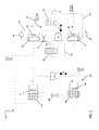
- the air temperature and humidity control device 10 generally includes a first heat pump 20 and a humidity controller 30.
- the closed loop first heat pump 20 includes a compressor 22, a condenser 24, an expansion valve 26, and an evaporator 28.
- a refrigerant R is circulated through the various components of the heat pump 20 in a known manner so that the refrigerant R is in a compressed state (releasing heat) in the condenser 24 and is in an expanded state (heat absorbing) in the evaporator 28.
- the refrigerant R may be an environmentally friendly refrigerant, such as R-410 for example; however other suitable refrigerants are within the scope of the invention.
- the humidity controller 30 includes a first contactor 32 having hygroscopic material L flowing there through, such as liquid desiccant including an aqueous lithium chloride solution for example.
- hygroscopic material L flowing there through
- the first heat pump 20 and humidity controller 30 may be thermally coupled together so as to allow the hygroscopic material L to be heated in the condenser 24 and cooled in the evaporator 28.
- the first contactor 32 is fluidly coupled to the evaporator 28 and the condenser 24 through a first conduit 34 and a second conduit 36, respectively.
- the hygroscopic material L may be driven by a pump 38 to flow sequentially through the evaporator 28, the first contactor 32, and the condenser 24.
- a first blower 40 is configured to generate an air flow A over the adjacent first contactor 32.
- the air flow A may include air from any of a number of sources including, but not limited to, process air, exhaust air, outdoor air, or a combination thereof for example.
- the first blower 40 may be an electric fan positioned adjacent to the first contactor 32, or an air outlet or exhaust of a heating ventilation and air conditioning (HVAC) system for example.
- HVAC heating ventilation and air conditioning
- HVAC heating ventilation and air conditioning
- the first contactor 32 serves as an absorber, transferring moisture and/or heat from the air flow A to the hygroscopic material L.
- the humidity controller 30 additionally includes a second contactor 42 through which the hygroscopic material L flows.
- the second contactor 42 may also be thermally coupled to the condenser 24 and the evaporator 28 through a third conduit 44 and a fourth conduit 46, respectively.
- the hygroscopic material L may be driven by the fluid pump 38 sequentially through the condenser 24, the second contactor 42, and the evaporator 28.
- More than one pump 38 may be used to drive the hygroscopic material L though the heat pump 20, such as to provide independent control of the flow of hygroscopic material L through the first contactor 32 and the second contactor 42, or to reduce the pressure within the humidity controller 30 to protect the first contactor 32 and the second contactor 42 from overpressure for example.
- one or more tanks (not shown) configured to store and supply hygroscopic material L may be included in the humidity controller 30.
- a second blower 48 may be provided to generate an air flow B over the second contactor 42. Similar to the air flow A over the first contactor 32, air flow B may include air from any of a number of sources including, but not limited to, process air, exhaust air, outdoor air, or a combination thereof for example.
- the second blower 48 may include an electric fan positioned adjacent to the second contactor 42, or alternatively, the electric fan may be substituted by an air outlet of an HVAC system.
- the air flow B passes over the second contactor 42, heat and/or water transfers between the air flow B and hygroscopic material L in the second contactor 42 to allow the device to provide a desirable air temperature and/or humidity.
- the second contactor 42 serves as a desorber, removing moisture to regenerate the hygroscopic material L.
- the evaporator 28 and the condenser 24 may be configured as refrigerant-hygroscopic material heat exchangers.
- the refrigerant-hygroscopic material heat exchangers may be of a shell-and-tube design, in which a bundle of tubes is disposed within an outer shell. In operation, one fluid flows through the tubes and another fluid flows along the tubes (through the shell) to allow heat transfer between the two fluids.
- the refrigerant-hygroscopic material heat exchangers may also be of a brazed or welded plate design for compactness and increased heat exchange effectiveness.
- the refrigerant-hygroscopic material heat exchangers described herein are exemplary and other suitable heat exchangers known to one of ordinary skill in the art are also within the scope of this invention.
- the humidity controller 30 may include a hygroscopic material-hygroscopic material heat exchanger (not shown) configured to recuperate heat between the flow of hygroscopic material L from the first contactor 32 and the flow of hygroscopic material L from the second contactor 42.
- the humidity controller may include one or more bypass flows so that at least a portion of the hygroscopic material L can bypass certain components of the humidity controller 30 to facilitate efficiency and control.
- each of the first and second contactors 32, 42 includes at least one contact module 50 having a porous sidewall 52 with an interior side 54 and an exterior side 56.
- the interior side 54 of the sidewall 52 defines an internal space 58 through which the hygroscopic material L flows.
- the contact modules 50 are substantially tubular in shape.
- contactors 32, 42 that use another known humidity absorbing/desorbing device or have other membrane configurations, such as a packed towers, packed beds, planar, spiral configuration for membranes or other separation methods or technologies for example, are within the scope of the invention.
- Each of the contactors 32, 42 may include at least one end connector (not shown) configured to establish fluid communication between the contact modules 50 and the desiccant conduits 34, 36, 44, 46.
- Suitable connectors include pipe manifolds, chamber manifolds, or other connectors generally used in fluid transportation.
- one or both of the contactors 32, 42 may include only one contact module 50, directly connected to the desiccant conduits 34, 36, 44, 46 without any connector.
- the porous sidewall 52 of the contact module 50 may be permeable to water vapor, and impermeable to the hygroscopic material L so as to form a closed loop.
- the porous sidewall 52 is made of a hydrophobic porous material, such as a plastic (polymeric) porous material for example.
- the air temperature and humidity control device 10 includes a second heat pump 60 having a first coil 62, such as an evaporator for example, a compressor 64, a second coil 66, such as a condenser for example, and an expansion valve 68.
- a first coil 62 such as an evaporator for example
- a compressor 64 such as a compressor 64
- a second coil 66 such as a condenser for example
- an expansion valve 68 exemplary embodiments of the second heat pump 60 include, but are not limited to, a residential air conditioning system, a roof top unit, and a chiller having an air handling unit for example.
- a third blower 67 is arranged generally adjacent the first coil 62 and a fourth blower 69 is arranged adjacent the second coil 66.
- the blowers 67, 69 are configured to provide a flow of air over the first coil 62 and second coil 66 respectively.
- a refrigerant R circulates through the various components of the second heat pump 60 in a known manner so that the refrigerant R is in a compressed state (releasing heat) in the second coil 66 and is in an expanded state (heat absorbing) in the first coil 62.
- at least one of the first coil 62 and the second coil 66 is configured as a refrigerant-air heat exchanger.
- the first heat pump 20 and the second heat pump 60 are illustrated in the FIGS. as simple vapor-compression systems, the heat pumps 20, 60 may include additional components known to a person skilled in the art.
- Exemplary components configured to enhance the efficiency or capacity of the heat pumps 20, 60 include, but are not limited to, work recovery devices (expanders, etc%), pressure recovery devices (ejectors, etc%), suction line heat exchangers, compressors with advanced technologies, and control systems for example.
- a control system 100 may be operably coupled to both the first heat pump 20 and the second heat pump 60.
- the control system 100 may be coupled to one or more components of each heat pump 20, 60, including, but not limited to the compressors 22, 64, the expansion valves 26, 68, the blowers 40, 48, 67, 69, or the one or more pumps 38 for example.
- the control system 100 is configured to control at least one of the flow of refrigerant R through both heat pumps 20, 60, the flow of hygroscopic material L through the humidity controller 30, and the flow of air over the contactors 32, 42 and the coils 62, 66 to optimize the performance of the air temperature and humidity control device 10.
- the first contactor 32 is arranged generally downstream of the evaporator 28 so that the hygroscopic material L may be cooled in the evaporator 28, such as to a temperature below the ambient temperature for example, before passing through the first contactor 32.
- the hygroscopic material L cools the at least one contact module 50 of the first contactor 32 as it flows there through.
- the cooled contact modules 50 are configured to absorb heat, for example from air flow A adjacent the exterior side 56 of the contact modules 50.
- the hygroscopic nature may cause the hygroscopic material L to absorb water vapor from the air flow A.
- the at least one contact module 50 of the first contactor 32 decreases both the temperature and the humidity of the air flow A along its exterior side 56.
- the first coil 62 of the second heat pump 60 may be generally aligned with and arranged downstream from the first contactor 32 such that the air flow A is cooled and dehumidified as it passes over the first contactor 32, and the air flow A is further cooled as it passes over the first coil 62.
- the device 10 may be configured such that the first coil 62 is positioned adjacent to an interior air vent of a facility to be air-conditioned so that the air flow A, after being cooled and dehumidified may be, for example, introduced into the facility for comfort.
- a separate air flow C may be configured to pass over the first coil 62 of the second heat pump 60. At least one of air flow A, after having been cooled and dehumidified by the first contactor 32, and air flow C, after having been cooled by the first coil 62, or a mixture thereof, may be provided to the facility to be air-conditioned.
- the second contactor 42 is positioned downstream from the condenser 24 such that as the hygroscopic material L passes through the condenser 24, the hygroscopic material L is heated, such as to a temperature above the ambient temperature for example. As the heated hygroscopic material L flows through the at least one contact module 50 of the second contactor 42, the water vapor differential across the porous sidewall 52 causes the hygroscopic material L to release water vapor into the air flow B. The resultant hygroscopic material L is more concentrated than the hygroscopic material L entering the second contactor 42.
- the at least one contact module 50 of the second contactor 42 heated by the hygroscopic material L flowing there through, releases heat to the air flow B along the exterior side 56 of the contact modules 50.
- the contact modules 50 of the second contactor 42 may function to increase both the temperature and humidity of the air flow B along its exterior side.
- the second coil 66 of the second heat pump 60 may be generally aligned with and arranged downstream from the second contactor 42. As illustrated in FIGS. 1 and 2 , a separate air flow D may be configured to flow over the second coil 66, by means of the fourth blower 69, and remove heat from the refrigerant R flowing there through.
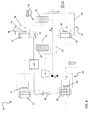
- first heat pump 20 and the second heat pump 60 may be integrated.
- a single compressor 70 may replace both compressors 22, 64.
- the flow between the two parallel heat pumps 20, 60 may be controlled with the control system 100.
- the first heat pump 20 and the second heat pump 60 may be operably coupled to form an integrated refrigerant loop 71 such that the evaporator 28 and the first coil 62 and/or the second coil 66 and the condenser 24 are arranged generally in series (see FIG. 5 ), or in parallel relative to the refrigerant flow path.
- the evaporator 28 and the first coil 62 arranged in series and the second coil 66 and the condenser 24 similarly arranged in series, the complexity of the device 10 is reduced and the controllability of the device 10 is generally improved.
- the efficiency of a device 10 having a portion of an integrally formed first heat pump 20 and a second heat pump 60 arranged generally in series may be improved by positioning a liquid-vapor separator 72 within the integrated refrigerant loop 71, such as between the evaporator 28 and the first coil 62 for example.
- the vapor within the separator 72 is provided to the compressor 70, and the liquid from the separator 72 is provided to the expansion valve 68 and then the first coil 62. Since the pressure of the vapor in the separator 72 is higher than the pressure at the first coil 62, the power required by the compressor 70 will be reduced by limiting the amount of flow through the first coil 62. As illustrated in FIG.
- the second coil 66 and the condenser 24 may be arranged in series, and the evaporator 28 and the first coil 62 may be arranged in parallel.
- a conduit 74 extending from the condenser 24 to the evaporator 28 includes the first expansion valve 26 and a conduit 76 extending from the condenser 24 to the first coil 62 includes the second expansion valve 68. The flow into each of the conduits 74, 76 is generally controlled by the first expansion valve 26 and the second expansion valve 68 respectively.
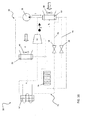
- first contactor 32 and the evaporator 28 are integrated into a first enthalpy device 80, arranged upstream from the compressor 22 and generally adjacent the first blower 40.
- the first enthalpy device 80 may be configured as a three-way heat exchanger such that heat and/or water vapor transfers between the refrigerant R, the hygroscopic material L, and the air flow A passing over the enthalpy device 80.
- the condenser 24 and the second contactor 42 may be integrated into a second enthalpy device 82 similarly configured such that heat and/or water vapor transfers between the refrigerant R, the hygroscopic material L, and the air flow B passing over the enthalpy device 82.
- the second enthalpy device 82 is positioned generally downstream from the compressor 22 adjacent the second blower 48.
- the first enthalpy device 80 and/or the second enthalpy device 82 may be integrated into any of the air temperature and humidity control devices 10 illustrated in the previous FIGS.
- the air temperature and humidity control device illustrated in FIG. 9 includes both a first enthalpy device 80 and a second enthalpy device 82.
- the second coil 66 is arranged downstream from the second enthalpy device 82 with respect to the refrigerant flow R.
- An air flow D distinct from the air flow B over the second enthalpy device 82, is configured to remove heat from the refrigerant R flowing through the second coil 66.
- the first coil 62 is arranged generally downstream from the first enthalpy device 80 with respect to both the refrigerant flow R and the air flow A. Similar to the configuration of the device 10 illustrated in FIG.
- a liquid-vapor separator 72 may be positioned between the first enthalpy device 80 and the first coil 62 within the integrated refrigeration loop. As previously described, vapor within the separator 72 is provided to the compressor 70, and the liquid from the separator 72 is provided to the expansion valve 68 and then the first coil 62.
- the air temperature and humidity control device 10 may be further simplified, as illustrated in FIG. 10 , by removing one of the coils 64, 68 from the integrated refrigerant loop 71.
- the device 10 includes a second enthalpy device 82
- the refrigerant R of the integrated refrigeration loop is cooled as it flows through the second enthalpy device 80 in a manner similar to the second coil 66.
- the device 10 includes a first enthalpy device 80
- the refrigerant R is generally heated within the first enthalpy device 80 in a manner similar to the first coil 62.
- the humidity controller 30 includes a second enthalpy device 82 and a first contactor 32, such that the evaporator 28 and the first coil 62 may be arranged generally in series (see FIG. 5 ) or in parallel relative to the flow of refrigerant R.
- the disclosed air temperature and humidity control device 10 may be arranged in any of a variety of configurations, allowing for tradeoffs between system complexity, cost, physical size, efficiency, and controllability.
Landscapes
- Engineering & Computer Science (AREA)
- Chemical & Material Sciences (AREA)
- Combustion & Propulsion (AREA)
- Mechanical Engineering (AREA)
- General Engineering & Computer Science (AREA)
- Central Air Conditioning (AREA)
- Drying Of Gases (AREA)
Applications Claiming Priority (1)
| Application Number | Priority Date | Filing Date | Title |
|---|---|---|---|
| US201361772240P | 2013-03-04 | 2013-03-04 |
Publications (2)
| Publication Number | Publication Date |
|---|---|
| EP2787293A1 true EP2787293A1 (de) | 2014-10-08 |
| EP2787293B1 EP2787293B1 (de) | 2019-01-02 |
Family
ID=50190324
Family Applications (1)
| Application Number | Title | Priority Date | Filing Date |
|---|---|---|---|
| EP14157538.1A Active EP2787293B1 (de) | 2013-03-04 | 2014-03-03 | Integriertes Membranentfeuchtungssystem |
Country Status (2)
| Country | Link |
|---|---|
| US (1) | US9267696B2 (de) |
| EP (1) | EP2787293B1 (de) |
Cited By (13)
| Publication number | Priority date | Publication date | Assignee | Title |
|---|---|---|---|---|
| EP3120083A4 (de) * | 2014-03-20 | 2017-11-29 | 7AC Technologies, Inc. | Flüssige trockenmittelsysteme und verfahren für ein dach |
| CN107490283A (zh) * | 2017-08-09 | 2017-12-19 | 江苏科技大学 | 可快速升温的热回收型调温热泵干燥装置及其运行方法 |
| US10006648B2 (en) | 2010-05-25 | 2018-06-26 | 7Ac Technologies, Inc. | Methods and systems for desiccant air conditioning |
| US10024601B2 (en) | 2012-12-04 | 2018-07-17 | 7Ac Technologies, Inc. | Methods and systems for cooling buildings with large heat loads using desiccant chillers |
| US10024558B2 (en) | 2014-11-21 | 2018-07-17 | 7Ac Technologies, Inc. | Methods and systems for mini-split liquid desiccant air conditioning |
| WO2019192210A1 (zh) * | 2018-04-04 | 2019-10-10 | 珠海格力电器股份有限公司 | 恒温恒湿内机、恒温恒湿系统及其控制方法 |
| US10443868B2 (en) | 2012-06-11 | 2019-10-15 | 7Ac Technologies, Inc. | Methods and systems for turbulent, corrosion resistant heat exchangers |
| US10619867B2 (en) | 2013-03-14 | 2020-04-14 | 7Ac Technologies, Inc. | Methods and systems for mini-split liquid desiccant air conditioning |
| US10619868B2 (en) | 2013-06-12 | 2020-04-14 | 7Ac Technologies, Inc. | In-ceiling liquid desiccant air conditioning system |
| US10760830B2 (en) | 2013-03-01 | 2020-09-01 | 7Ac Technologies, Inc. | Desiccant air conditioning methods and systems |
| US10921001B2 (en) | 2017-11-01 | 2021-02-16 | 7Ac Technologies, Inc. | Methods and apparatus for uniform distribution of liquid desiccant in membrane modules in liquid desiccant air-conditioning systems |
| US10941948B2 (en) | 2017-11-01 | 2021-03-09 | 7Ac Technologies, Inc. | Tank system for liquid desiccant air conditioning system |
| US11022330B2 (en) | 2018-05-18 | 2021-06-01 | Emerson Climate Technologies, Inc. | Three-way heat exchangers for liquid desiccant air-conditioning systems and methods of manufacture |
Families Citing this family (12)
| Publication number | Priority date | Publication date | Assignee | Title |
|---|---|---|---|---|
| CN104096459B (zh) * | 2010-09-07 | 2018-05-11 | 戴斯分析公司 | 使用选择性传递膜的流体处理系统和方法 |
| US9464815B2 (en) * | 2014-11-04 | 2016-10-11 | Lennox Industries Inc. | HVAC systems and methods with improved humidity regulation |
| US20180209670A1 (en) * | 2017-01-20 | 2018-07-26 | Carrier Corporation | Moisture separation system |
| CN108332442B (zh) * | 2018-03-13 | 2024-04-02 | 中铁工程设计咨询集团有限公司 | 一种二氧化碳热泵水力模块机组 |
| US11592215B2 (en) | 2018-08-29 | 2023-02-28 | Waterfurnace International, Inc. | Integrated demand water heating using a capacity modulated heat pump with desuperheater |
| CN110243024B (zh) * | 2019-06-17 | 2021-07-16 | 东莞理工学院 | 一种家用膜式溶液除湿机 |
| JP6843941B2 (ja) * | 2019-10-08 | 2021-03-17 | 清水建設株式会社 | 空調システム |
| CN112484233B (zh) * | 2020-11-27 | 2021-11-23 | 珠海格力电器股份有限公司 | 一种直膨式空调机组系统的控制方法、装置和空调机 |
| US20230194108A1 (en) * | 2021-12-17 | 2023-06-22 | Emerson Climate Technologies, Inc. | Conditioning system including vapor compression system and humidity control system |
| US12571546B2 (en) | 2022-04-13 | 2026-03-10 | Mojave Energy Systems, Inc. | Liquid desiccant air conditioning using air as heat transfer medium |
| KR102915877B1 (ko) * | 2022-11-17 | 2026-01-21 | 엘지전자 주식회사 | 공기 조화기 |
| US12337371B1 (en) | 2023-12-20 | 2025-06-24 | Copeland Lp | Systems and methods for assembling liquid desiccant air conditioner panels using flexible alignment features |
Citations (4)
| Publication number | Priority date | Publication date | Assignee | Title |
|---|---|---|---|---|
| WO1988008947A1 (en) * | 1987-05-12 | 1988-11-17 | Purde, John, C. | Air conditioning apparatus |
| WO2000055546A1 (en) * | 1999-03-14 | 2000-09-21 | Drykor Ltd. | Dehumidifier/air-conditioning system |
| US6247323B1 (en) * | 1997-04-11 | 2001-06-19 | Ebara Corporation | Air-conditioning system |
| WO2012042553A1 (en) * | 2010-09-30 | 2012-04-05 | Universita' Degli Studi Di Genova | Contactor module with hydrophobic capillary membranes, integrated in a heat exchanger and hybrid plant for the dehumidification/conditioning of air |
Family Cites Families (27)
| Publication number | Priority date | Publication date | Assignee | Title |
|---|---|---|---|---|
| US4171624A (en) | 1976-04-16 | 1979-10-23 | Gershon Meckler Associates, P.C. | Air conditioning apparatus |
| US4171620A (en) * | 1976-11-18 | 1979-10-23 | Turner Nelson C | Cooling method and system |
| DK148195C (da) * | 1977-01-10 | 1986-04-01 | Erling Lauritz Anderberg | Gasaffugtningsapparat |
| US4180985A (en) | 1977-12-01 | 1980-01-01 | Northrup, Incorporated | Air conditioning system with regeneratable desiccant bed |
| US4300623A (en) * | 1978-10-10 | 1981-11-17 | Milton Meckler | Integrated multi-duct dual-stage dual-cooling media air conditioning system |
| US4222244A (en) * | 1978-11-07 | 1980-09-16 | Gershon Meckler Associates, P.C. | Air conditioning apparatus utilizing solar energy and method |
| US4430864A (en) | 1981-12-31 | 1984-02-14 | Midwest Research Institute | Hybrid vapor compression and desiccant air conditioning system |
| US4987750A (en) * | 1986-07-08 | 1991-01-29 | Gershon Meckler | Air conditioning apparatus |
| US5471852A (en) * | 1991-07-05 | 1995-12-05 | Meckler; Milton | Polymer enhanced glycol desiccant heat-pipe air dehumidifier preconditioning system |
| US5460004A (en) | 1993-04-09 | 1995-10-24 | Ari-Tec Marketing, Inc. | Desiccant cooling system with evaporative cooling |
| US5528905A (en) * | 1994-03-25 | 1996-06-25 | Essex Invention S.A. | Contactor, particularly a vapour exchanger for the control of the air hygrometric content, and a device for air handling |
| US6018954A (en) * | 1995-04-20 | 2000-02-01 | Assaf; Gad | Heat pump system and method for air-conditioning |
| US6405543B2 (en) | 1997-05-16 | 2002-06-18 | Work Smart Energy Enterprises Inc. | High-efficiency air-conditioning system with high-volume air distribution |
| US5953926A (en) * | 1997-08-05 | 1999-09-21 | Tennessee Valley Authority | Heating, cooling, and dehumidifying system with energy recovery |
| IL141579A0 (en) * | 2001-02-21 | 2002-03-10 | Drykor Ltd | Dehumidifier/air-conditioning system |
| US6216489B1 (en) | 1997-12-04 | 2001-04-17 | Fedders Corporation | Liquid desiccant air conditioner |
| US6513339B1 (en) | 1999-04-16 | 2003-02-04 | Work Smart Energy Enterprises, Inc. | Solar air conditioner |
| US6497107B2 (en) | 2000-07-27 | 2002-12-24 | Idalex Technologies, Inc. | Method and apparatus of indirect-evaporation cooling |
| DE10059910C2 (de) * | 2000-12-01 | 2003-01-16 | Daimler Chrysler Ag | Vorrichtung zur kontinuierlichen Befeuchtung und Entfeuchtung der Zuluft von Fertigungsprozessen oder Raumlufttechnik-Anlagen |
| EP1475576A4 (de) * | 2002-02-12 | 2009-12-09 | Panasonic Corp | Wassererhitzer für wärmepumpe |
| US20050109052A1 (en) * | 2003-09-30 | 2005-05-26 | Albers Walter F. | Systems and methods for conditioning air and transferring heat and mass between airflows |
| JP3668785B2 (ja) | 2003-10-09 | 2005-07-06 | ダイキン工業株式会社 | 空気調和装置 |
| JP3861902B2 (ja) | 2004-09-09 | 2006-12-27 | ダイキン工業株式会社 | 調湿装置 |
| JP4775623B2 (ja) * | 2004-10-26 | 2011-09-21 | 株式会社日立プラントテクノロジー | 除湿システム |
| JP4321650B2 (ja) | 2007-12-07 | 2009-08-26 | ダイキン工業株式会社 | 調湿装置 |
| JP5248629B2 (ja) | 2008-01-25 | 2013-07-31 | アライアンス フォー サステイナブル エナジー リミテッド ライアビリティ カンパニー | 除湿のために、膜に含有された液体乾燥剤を用いる間接蒸発冷却器 |
| KR102107636B1 (ko) * | 2010-05-25 | 2020-05-29 | 7에이씨 테크놀로지스, 아이엔씨. | 공조 및 다른 프로세스들을 위해 액체 흡습제들을 이용하는 방법들 및 시스템들 |
-
2014
- 2014-02-27 US US14/191,656 patent/US9267696B2/en active Active
- 2014-03-03 EP EP14157538.1A patent/EP2787293B1/de active Active
Patent Citations (4)
| Publication number | Priority date | Publication date | Assignee | Title |
|---|---|---|---|---|
| WO1988008947A1 (en) * | 1987-05-12 | 1988-11-17 | Purde, John, C. | Air conditioning apparatus |
| US6247323B1 (en) * | 1997-04-11 | 2001-06-19 | Ebara Corporation | Air-conditioning system |
| WO2000055546A1 (en) * | 1999-03-14 | 2000-09-21 | Drykor Ltd. | Dehumidifier/air-conditioning system |
| WO2012042553A1 (en) * | 2010-09-30 | 2012-04-05 | Universita' Degli Studi Di Genova | Contactor module with hydrophobic capillary membranes, integrated in a heat exchanger and hybrid plant for the dehumidification/conditioning of air |
Cited By (21)
| Publication number | Priority date | Publication date | Assignee | Title |
|---|---|---|---|---|
| US11624517B2 (en) | 2010-05-25 | 2023-04-11 | Emerson Climate Technologies, Inc. | Liquid desiccant air conditioning systems and methods |
| US10006648B2 (en) | 2010-05-25 | 2018-06-26 | 7Ac Technologies, Inc. | Methods and systems for desiccant air conditioning |
| US10168056B2 (en) | 2010-05-25 | 2019-01-01 | 7Ac Technologies, Inc. | Desiccant air conditioning methods and systems using evaporative chiller |
| US10753624B2 (en) | 2010-05-25 | 2020-08-25 | 7Ac Technologies, Inc. | Desiccant air conditioning methods and systems using evaporative chiller |
| US10443868B2 (en) | 2012-06-11 | 2019-10-15 | 7Ac Technologies, Inc. | Methods and systems for turbulent, corrosion resistant heat exchangers |
| US11098909B2 (en) | 2012-06-11 | 2021-08-24 | Emerson Climate Technologies, Inc. | Methods and systems for turbulent, corrosion resistant heat exchangers |
| US10024601B2 (en) | 2012-12-04 | 2018-07-17 | 7Ac Technologies, Inc. | Methods and systems for cooling buildings with large heat loads using desiccant chillers |
| US10760830B2 (en) | 2013-03-01 | 2020-09-01 | 7Ac Technologies, Inc. | Desiccant air conditioning methods and systems |
| US10619867B2 (en) | 2013-03-14 | 2020-04-14 | 7Ac Technologies, Inc. | Methods and systems for mini-split liquid desiccant air conditioning |
| US10619868B2 (en) | 2013-06-12 | 2020-04-14 | 7Ac Technologies, Inc. | In-ceiling liquid desiccant air conditioning system |
| US10323867B2 (en) | 2014-03-20 | 2019-06-18 | 7Ac Technologies, Inc. | Rooftop liquid desiccant systems and methods |
| US10619895B1 (en) | 2014-03-20 | 2020-04-14 | 7Ac Technologies, Inc. | Rooftop liquid desiccant systems and methods |
| EP3120083A4 (de) * | 2014-03-20 | 2017-11-29 | 7AC Technologies, Inc. | Flüssige trockenmittelsysteme und verfahren für ein dach |
| US10731876B2 (en) | 2014-11-21 | 2020-08-04 | 7Ac Technologies, Inc. | Methods and systems for mini-split liquid desiccant air conditioning |
| US10024558B2 (en) | 2014-11-21 | 2018-07-17 | 7Ac Technologies, Inc. | Methods and systems for mini-split liquid desiccant air conditioning |
| CN107490283B (zh) * | 2017-08-09 | 2019-09-03 | 江苏科技大学 | 可快速升温的热回收型调温热泵干燥装置及其运行方法 |
| CN107490283A (zh) * | 2017-08-09 | 2017-12-19 | 江苏科技大学 | 可快速升温的热回收型调温热泵干燥装置及其运行方法 |
| US10921001B2 (en) | 2017-11-01 | 2021-02-16 | 7Ac Technologies, Inc. | Methods and apparatus for uniform distribution of liquid desiccant in membrane modules in liquid desiccant air-conditioning systems |
| US10941948B2 (en) | 2017-11-01 | 2021-03-09 | 7Ac Technologies, Inc. | Tank system for liquid desiccant air conditioning system |
| WO2019192210A1 (zh) * | 2018-04-04 | 2019-10-10 | 珠海格力电器股份有限公司 | 恒温恒湿内机、恒温恒湿系统及其控制方法 |
| US11022330B2 (en) | 2018-05-18 | 2021-06-01 | Emerson Climate Technologies, Inc. | Three-way heat exchangers for liquid desiccant air-conditioning systems and methods of manufacture |
Also Published As
| Publication number | Publication date |
|---|---|
| EP2787293B1 (de) | 2019-01-02 |
| US20140245772A1 (en) | 2014-09-04 |
| US9267696B2 (en) | 2016-02-23 |
Similar Documents
| Publication | Publication Date | Title |
|---|---|---|
| US9267696B2 (en) | Integrated membrane dehumidification system | |
| US9511322B2 (en) | Dehumidification system for air conditioning | |
| US10222078B2 (en) | Method and device for air conditioning with humidity control | |
| US10041692B2 (en) | Regeneration air mixing for a membrane based hygroscopic material dehumidification system | |
| US11761645B2 (en) | Energy exchange system for conditioning air in an enclosed structure | |
| CN110715390B (zh) | 用于具有冷流体回路的建筑物的空气调节系统 | |
| CN106062483B (zh) | 热泵除湿的增强方法 | |
| CN103827589A (zh) | 除湿系统 | |
| JP2013064549A (ja) | 空調システム | |
| JP6377933B2 (ja) | 外気処理装置 | |
| JP2010112633A (ja) | デシカント空調装置 | |
| JP2017009187A (ja) | 空調装置 | |
| CN103791652A (zh) | 一种双温热源热泵系统 | |
| JP6089697B2 (ja) | 調湿装置 | |
| JP2008190798A (ja) | 除湿空調装置 |
Legal Events
| Date | Code | Title | Description |
|---|---|---|---|
| PUAI | Public reference made under article 153(3) epc to a published international application that has entered the european phase |
Free format text: ORIGINAL CODE: 0009012 |
|
| 17P | Request for examination filed |
Effective date: 20140303 |
|
| AK | Designated contracting states |
Kind code of ref document: A1 Designated state(s): AL AT BE BG CH CY CZ DE DK EE ES FI FR GB GR HR HU IE IS IT LI LT LU LV MC MK MT NL NO PL PT RO RS SE SI SK SM TR |
|
| AX | Request for extension of the european patent |
Extension state: BA ME |
|
| R17P | Request for examination filed (corrected) |
Effective date: 20150407 |
|
| RBV | Designated contracting states (corrected) |
Designated state(s): AL AT BE BG CH CY CZ DE DK EE ES FI FR GB GR HR HU IE IS IT LI LT LU LV MC MK MT NL NO PL PT RO RS SE SI SK SM TR |
|
| GRAP | Despatch of communication of intention to grant a patent |
Free format text: ORIGINAL CODE: EPIDOSNIGR1 |
|
| STAA | Information on the status of an ep patent application or granted ep patent |
Free format text: STATUS: GRANT OF PATENT IS INTENDED |
|
| INTG | Intention to grant announced |
Effective date: 20180626 |
|
| GRAS | Grant fee paid |
Free format text: ORIGINAL CODE: EPIDOSNIGR3 |
|
| GRAJ | Information related to disapproval of communication of intention to grant by the applicant or resumption of examination proceedings by the epo deleted |
Free format text: ORIGINAL CODE: EPIDOSDIGR1 |
|
| GRAL | Information related to payment of fee for publishing/printing deleted |
Free format text: ORIGINAL CODE: EPIDOSDIGR3 |
|
| STAA | Information on the status of an ep patent application or granted ep patent |
Free format text: STATUS: REQUEST FOR EXAMINATION WAS MADE |
|
| GRAR | Information related to intention to grant a patent recorded |
Free format text: ORIGINAL CODE: EPIDOSNIGR71 |
|
| STAA | Information on the status of an ep patent application or granted ep patent |
Free format text: STATUS: GRANT OF PATENT IS INTENDED |
|
| GRAA | (expected) grant |
Free format text: ORIGINAL CODE: 0009210 |
|
| STAA | Information on the status of an ep patent application or granted ep patent |
Free format text: STATUS: THE PATENT HAS BEEN GRANTED |
|
| INTC | Intention to grant announced (deleted) | ||
| AK | Designated contracting states |
Kind code of ref document: B1 Designated state(s): AL AT BE BG CH CY CZ DE DK EE ES FI FR GB GR HR HU IE IS IT LI LT LU LV MC MK MT NL NO PL PT RO RS SE SI SK SM TR |
|
| INTG | Intention to grant announced |
Effective date: 20181126 |
|
| REG | Reference to a national code |
Ref country code: GB Ref legal event code: FG4D |
|
| REG | Reference to a national code |
Ref country code: CH Ref legal event code: EP Ref country code: AT Ref legal event code: REF Ref document number: 1084884 Country of ref document: AT Kind code of ref document: T Effective date: 20190115 |
|
| REG | Reference to a national code |
Ref country code: IE Ref legal event code: FG4D |
|
| REG | Reference to a national code |
Ref country code: DE Ref legal event code: R096 Ref document number: 602014038954 Country of ref document: DE |
|
| REG | Reference to a national code |
Ref country code: NL Ref legal event code: FP |
|
| REG | Reference to a national code |
Ref country code: LT Ref legal event code: MG4D |
|
| REG | Reference to a national code |
Ref country code: AT Ref legal event code: MK05 Ref document number: 1084884 Country of ref document: AT Kind code of ref document: T Effective date: 20190102 |
|
| PG25 | Lapsed in a contracting state [announced via postgrant information from national office to epo] |
Ref country code: PT Free format text: LAPSE BECAUSE OF FAILURE TO SUBMIT A TRANSLATION OF THE DESCRIPTION OR TO PAY THE FEE WITHIN THE PRESCRIBED TIME-LIMIT Effective date: 20190502 Ref country code: ES Free format text: LAPSE BECAUSE OF FAILURE TO SUBMIT A TRANSLATION OF THE DESCRIPTION OR TO PAY THE FEE WITHIN THE PRESCRIBED TIME-LIMIT Effective date: 20190102 Ref country code: LT Free format text: LAPSE BECAUSE OF FAILURE TO SUBMIT A TRANSLATION OF THE DESCRIPTION OR TO PAY THE FEE WITHIN THE PRESCRIBED TIME-LIMIT Effective date: 20190102 Ref country code: NO Free format text: LAPSE BECAUSE OF FAILURE TO SUBMIT A TRANSLATION OF THE DESCRIPTION OR TO PAY THE FEE WITHIN THE PRESCRIBED TIME-LIMIT Effective date: 20190402 Ref country code: PL Free format text: LAPSE BECAUSE OF FAILURE TO SUBMIT A TRANSLATION OF THE DESCRIPTION OR TO PAY THE FEE WITHIN THE PRESCRIBED TIME-LIMIT Effective date: 20190102 Ref country code: SE Free format text: LAPSE BECAUSE OF FAILURE TO SUBMIT A TRANSLATION OF THE DESCRIPTION OR TO PAY THE FEE WITHIN THE PRESCRIBED TIME-LIMIT Effective date: 20190102 Ref country code: FI Free format text: LAPSE BECAUSE OF FAILURE TO SUBMIT A TRANSLATION OF THE DESCRIPTION OR TO PAY THE FEE WITHIN THE PRESCRIBED TIME-LIMIT Effective date: 20190102 |
|
| PG25 | Lapsed in a contracting state [announced via postgrant information from national office to epo] |
Ref country code: BG Free format text: LAPSE BECAUSE OF FAILURE TO SUBMIT A TRANSLATION OF THE DESCRIPTION OR TO PAY THE FEE WITHIN THE PRESCRIBED TIME-LIMIT Effective date: 20190402 Ref country code: IS Free format text: LAPSE BECAUSE OF FAILURE TO SUBMIT A TRANSLATION OF THE DESCRIPTION OR TO PAY THE FEE WITHIN THE PRESCRIBED TIME-LIMIT Effective date: 20190502 Ref country code: GR Free format text: LAPSE BECAUSE OF FAILURE TO SUBMIT A TRANSLATION OF THE DESCRIPTION OR TO PAY THE FEE WITHIN THE PRESCRIBED TIME-LIMIT Effective date: 20190403 Ref country code: RS Free format text: LAPSE BECAUSE OF FAILURE TO SUBMIT A TRANSLATION OF THE DESCRIPTION OR TO PAY THE FEE WITHIN THE PRESCRIBED TIME-LIMIT Effective date: 20190102 Ref country code: LV Free format text: LAPSE BECAUSE OF FAILURE TO SUBMIT A TRANSLATION OF THE DESCRIPTION OR TO PAY THE FEE WITHIN THE PRESCRIBED TIME-LIMIT Effective date: 20190102 Ref country code: HR Free format text: LAPSE BECAUSE OF FAILURE TO SUBMIT A TRANSLATION OF THE DESCRIPTION OR TO PAY THE FEE WITHIN THE PRESCRIBED TIME-LIMIT Effective date: 20190102 |
|
| REG | Reference to a national code |
Ref country code: DE Ref legal event code: R119 Ref document number: 602014038954 Country of ref document: DE |
|
| REG | Reference to a national code |
Ref country code: DE Ref legal event code: R097 Ref document number: 602014038954 Country of ref document: DE |
|
| PG25 | Lapsed in a contracting state [announced via postgrant information from national office to epo] |
Ref country code: RO Free format text: LAPSE BECAUSE OF FAILURE TO SUBMIT A TRANSLATION OF THE DESCRIPTION OR TO PAY THE FEE WITHIN THE PRESCRIBED TIME-LIMIT Effective date: 20190102 Ref country code: IT Free format text: LAPSE BECAUSE OF FAILURE TO SUBMIT A TRANSLATION OF THE DESCRIPTION OR TO PAY THE FEE WITHIN THE PRESCRIBED TIME-LIMIT Effective date: 20190102 Ref country code: SK Free format text: LAPSE BECAUSE OF FAILURE TO SUBMIT A TRANSLATION OF THE DESCRIPTION OR TO PAY THE FEE WITHIN THE PRESCRIBED TIME-LIMIT Effective date: 20190102 Ref country code: CZ Free format text: LAPSE BECAUSE OF FAILURE TO SUBMIT A TRANSLATION OF THE DESCRIPTION OR TO PAY THE FEE WITHIN THE PRESCRIBED TIME-LIMIT Effective date: 20190102 Ref country code: AL Free format text: LAPSE BECAUSE OF FAILURE TO SUBMIT A TRANSLATION OF THE DESCRIPTION OR TO PAY THE FEE WITHIN THE PRESCRIBED TIME-LIMIT Effective date: 20190102 Ref country code: MC Free format text: LAPSE BECAUSE OF FAILURE TO SUBMIT A TRANSLATION OF THE DESCRIPTION OR TO PAY THE FEE WITHIN THE PRESCRIBED TIME-LIMIT Effective date: 20190102 Ref country code: AT Free format text: LAPSE BECAUSE OF FAILURE TO SUBMIT A TRANSLATION OF THE DESCRIPTION OR TO PAY THE FEE WITHIN THE PRESCRIBED TIME-LIMIT Effective date: 20190102 Ref country code: DK Free format text: LAPSE BECAUSE OF FAILURE TO SUBMIT A TRANSLATION OF THE DESCRIPTION OR TO PAY THE FEE WITHIN THE PRESCRIBED TIME-LIMIT Effective date: 20190102 Ref country code: EE Free format text: LAPSE BECAUSE OF FAILURE TO SUBMIT A TRANSLATION OF THE DESCRIPTION OR TO PAY THE FEE WITHIN THE PRESCRIBED TIME-LIMIT Effective date: 20190102 |
|
| REG | Reference to a national code |
Ref country code: CH Ref legal event code: PL |
|
| PLBE | No opposition filed within time limit |
Free format text: ORIGINAL CODE: 0009261 |
|
| STAA | Information on the status of an ep patent application or granted ep patent |
Free format text: STATUS: NO OPPOSITION FILED WITHIN TIME LIMIT |
|
| PG25 | Lapsed in a contracting state [announced via postgrant information from national office to epo] |
Ref country code: SM Free format text: LAPSE BECAUSE OF FAILURE TO SUBMIT A TRANSLATION OF THE DESCRIPTION OR TO PAY THE FEE WITHIN THE PRESCRIBED TIME-LIMIT Effective date: 20190102 Ref country code: LU Free format text: LAPSE BECAUSE OF NON-PAYMENT OF DUE FEES Effective date: 20190303 |
|
| REG | Reference to a national code |
Ref country code: BE Ref legal event code: MM Effective date: 20190331 |
|
| 26N | No opposition filed |
Effective date: 20191003 |
|
| GBPC | Gb: european patent ceased through non-payment of renewal fee |
Effective date: 20190402 |
|
| PG25 | Lapsed in a contracting state [announced via postgrant information from national office to epo] |
Ref country code: LI Free format text: LAPSE BECAUSE OF NON-PAYMENT OF DUE FEES Effective date: 20190331 Ref country code: DE Free format text: LAPSE BECAUSE OF NON-PAYMENT OF DUE FEES Effective date: 20191001 Ref country code: IE Free format text: LAPSE BECAUSE OF NON-PAYMENT OF DUE FEES Effective date: 20190303 Ref country code: CH Free format text: LAPSE BECAUSE OF NON-PAYMENT OF DUE FEES Effective date: 20190331 Ref country code: GB Free format text: LAPSE BECAUSE OF NON-PAYMENT OF DUE FEES Effective date: 20190402 |
|
| PG25 | Lapsed in a contracting state [announced via postgrant information from national office to epo] |
Ref country code: SI Free format text: LAPSE BECAUSE OF FAILURE TO SUBMIT A TRANSLATION OF THE DESCRIPTION OR TO PAY THE FEE WITHIN THE PRESCRIBED TIME-LIMIT Effective date: 20190102 Ref country code: BE Free format text: LAPSE BECAUSE OF NON-PAYMENT OF DUE FEES Effective date: 20190331 |
|
| PG25 | Lapsed in a contracting state [announced via postgrant information from national office to epo] |
Ref country code: TR Free format text: LAPSE BECAUSE OF FAILURE TO SUBMIT A TRANSLATION OF THE DESCRIPTION OR TO PAY THE FEE WITHIN THE PRESCRIBED TIME-LIMIT Effective date: 20190102 |
|
| PG25 | Lapsed in a contracting state [announced via postgrant information from national office to epo] |
Ref country code: MT Free format text: LAPSE BECAUSE OF NON-PAYMENT OF DUE FEES Effective date: 20190303 |
|
| PG25 | Lapsed in a contracting state [announced via postgrant information from national office to epo] |
Ref country code: CY Free format text: LAPSE BECAUSE OF FAILURE TO SUBMIT A TRANSLATION OF THE DESCRIPTION OR TO PAY THE FEE WITHIN THE PRESCRIBED TIME-LIMIT Effective date: 20190102 |
|
| PG25 | Lapsed in a contracting state [announced via postgrant information from national office to epo] |
Ref country code: HU Free format text: LAPSE BECAUSE OF FAILURE TO SUBMIT A TRANSLATION OF THE DESCRIPTION OR TO PAY THE FEE WITHIN THE PRESCRIBED TIME-LIMIT; INVALID AB INITIO Effective date: 20140303 |
|
| PG25 | Lapsed in a contracting state [announced via postgrant information from national office to epo] |
Ref country code: MK Free format text: LAPSE BECAUSE OF FAILURE TO SUBMIT A TRANSLATION OF THE DESCRIPTION OR TO PAY THE FEE WITHIN THE PRESCRIBED TIME-LIMIT Effective date: 20190102 |
|
| PGFP | Annual fee paid to national office [announced via postgrant information from national office to epo] |
Ref country code: NL Payment date: 20250219 Year of fee payment: 12 |
|
| PGFP | Annual fee paid to national office [announced via postgrant information from national office to epo] |
Ref country code: FR Payment date: 20250219 Year of fee payment: 12 |