EP2787220A2 - Fastening element for furniture manufacture - Google Patents
Fastening element for furniture manufacture Download PDFInfo
- Publication number
- EP2787220A2 EP2787220A2 EP14163344.6A EP14163344A EP2787220A2 EP 2787220 A2 EP2787220 A2 EP 2787220A2 EP 14163344 A EP14163344 A EP 14163344A EP 2787220 A2 EP2787220 A2 EP 2787220A2
- Authority
- EP
- European Patent Office
- Prior art keywords
- holding
- holding part
- fastening element
- adjusting
- stop
- Prior art date
- Legal status (The legal status is an assumption and is not a legal conclusion. Google has not performed a legal analysis and makes no representation as to the accuracy of the status listed.)
- Granted
Links
- 238000004519 manufacturing process Methods 0.000 title 1
- 230000033001 locomotion Effects 0.000 claims abstract description 33
- 238000003780 insertion Methods 0.000 claims abstract description 29
- 230000037431 insertion Effects 0.000 claims abstract description 29
- 238000010276 construction Methods 0.000 claims abstract 2
- 230000013011 mating Effects 0.000 claims description 2
- 238000010008 shearing Methods 0.000 description 3
- 230000007480 spreading Effects 0.000 description 3
- 238000005452 bending Methods 0.000 description 2
- 230000000694 effects Effects 0.000 description 2
- 230000003993 interaction Effects 0.000 description 2
- 230000001419 dependent effect Effects 0.000 description 1
- 238000011161 development Methods 0.000 description 1
- 230000018109 developmental process Effects 0.000 description 1
- 238000007373 indentation Methods 0.000 description 1
- 239000000463 material Substances 0.000 description 1
- 230000007246 mechanism Effects 0.000 description 1
- 239000002184 metal Substances 0.000 description 1
- 230000004048 modification Effects 0.000 description 1
- 238000012986 modification Methods 0.000 description 1
- 239000002023 wood Substances 0.000 description 1
Images


Classifications
-
- F—MECHANICAL ENGINEERING; LIGHTING; HEATING; WEAPONS; BLASTING
- F16—ENGINEERING ELEMENTS AND UNITS; GENERAL MEASURES FOR PRODUCING AND MAINTAINING EFFECTIVE FUNCTIONING OF MACHINES OR INSTALLATIONS; THERMAL INSULATION IN GENERAL
- F16B—DEVICES FOR FASTENING OR SECURING CONSTRUCTIONAL ELEMENTS OR MACHINE PARTS TOGETHER, e.g. NAILS, BOLTS, CIRCLIPS, CLAMPS, CLIPS OR WEDGES; JOINTS OR JOINTING
- F16B12/00—Jointing of furniture or the like, e.g. hidden from exterior
- F16B12/10—Jointing of furniture or the like, e.g. hidden from exterior using pegs, bolts, tenons, clamps, clips, or the like
- F16B12/12—Jointing of furniture or the like, e.g. hidden from exterior using pegs, bolts, tenons, clamps, clips, or the like for non-metal furniture parts, e.g. made of wood, of plastics
- F16B12/24—Jointing of furniture or the like, e.g. hidden from exterior using pegs, bolts, tenons, clamps, clips, or the like for non-metal furniture parts, e.g. made of wood, of plastics using separate pins, dowels, or the like
-
- A—HUMAN NECESSITIES
- A47—FURNITURE; DOMESTIC ARTICLES OR APPLIANCES; COFFEE MILLS; SPICE MILLS; SUCTION CLEANERS IN GENERAL
- A47B—TABLES; DESKS; OFFICE FURNITURE; CABINETS; DRAWERS; GENERAL DETAILS OF FURNITURE
- A47B2230/00—Furniture jointing; Furniture with such jointing
- A47B2230/0029—Dowels
- A47B2230/0051—Two-piece dowels
Definitions
- the counter portion and the at least one stop element are coordinated such that, starting from the insertion position in the linear relative movement of the actuating part and holding part for setting the holding position, the at least one stop element moves away from the above position.
- the further linear relative movement is possible.
- a further impressions of the actuating part in the holding part is removed with the moving away of the stop element of the resistance by the stop element in the stop position against a relative movement of the actuating part and holding part in Ansteckraum.
- the stop element is present on the fastening element in such a way that, when a pushing-in force acting on the stop element is exceeded, the stop element, for example, articulates or is bent over in an articulated manner.
- guiding portions cooperating with one another on the holding part and the setting part are present in such a way that the linear relative movement between the holding part and the setting part for the adjustment of the holding section is guided by the guide sections can be specified.
- a force effect in the direction transverse thereto or provided to the outside over the guide portions for example in the direction of relative movement obliquely aligned surfaces on the control part and mating surfaces on the holding part, so that widened by a wedge effect with the movement of these inclined surfaces of the holding section to the outside or spread.
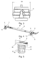
- FIG. 3 shows the expansion dowel 1 in a holding position of the expansion anchor 1, in which the holding part 2 is held clamped in a corresponding, in particular cylindrically shaped opening or a prepared receiving volume (not shown), for example in a furniture part area.
- front hooks 6 are for mounting the two expansion dowel 1a, 1b two round holes 7 and 8 prepared present and back additionally next to each two not visible in the figures wells, in which the two insertion pins 9, 10th fit exactly.
Landscapes
- Engineering & Computer Science (AREA)
- General Engineering & Computer Science (AREA)
- Mechanical Engineering (AREA)
- Connection Of Plates (AREA)
- Furniture Connections (AREA)
Abstract
Es wird ein Befestigungselement (1) für den Möbelbau vorgeschlagen mit einem Halteteil (2), das für eine Befestigungsfunktion in ein vertieftes Aufnahmevolumen einbringbar und anschließend in eine Haltestellung des Befestigungselements (1) durch ein Aufweiten eines Halteabschnitts (11) am Halteteil (2) verstellbar ist, und mit einem auf das Halteteil (2) derart abgestimmten Stellteil (3), dass mit einer linearen Relativbewegung zwischen dem Halteteil (2) und dem am Halteteil (2) funktionsrichtig angebrachten Stellteil (3) die Haltestellung einrichtbar ist, wobei das Stellteil (3) in der Haltestellung am Halteteil (2) verbleibt. Erfindungsgemäß sind am Stellteil (3) über eine Außenkontur des Stellteils (3) vorstehende Anschlagmittel vorhanden, die eine Einsteckposition des Stellteils (3) am Halteteil (2) bestimmen, in welcher das funktionsrichtig am Halteteil (2) angebrachte Stellteil (3) am Halteteil (2) eingesteckt ist und das Stellteil (3) und das Halteteil (2) aneinander gehalten sind, wobei in der Einsteckposition der Halteabschnitt (11) nicht verstellt ist.It is proposed a fastening element (1) for furniture construction with a holding part (2) which can be introduced for a fastening function in a recessed receiving volume and then in a holding position of the fastening element (1) by a widening of a holding portion (11) on the holding part (2). is adjustable, and with a on the holding part (2) so tuned control part (3) that with a linear relative movement between the holding part (2) and the holding part (2) functionally correct mounted actuating part (3), the holding position can be set, wherein the Setting part (3) in the holding position on the holding part (2) remains. According to the invention on the adjusting part (3) via an outer contour of the actuating part (3) projecting stop means are provided which determine a plug-in position of the adjusting part (3) on the holding part (2), in which the functionally correct on the holding part (2) mounted actuating part (3) on the holding part (2) is inserted and the adjusting part (3) and the holding part (2) are held together, wherein in the insertion position of the holding portion (11) is not adjusted.
Description
Befestigungselemente für den Möbelbau mit einem aufweitbaren Halteabschnitt sind bekannt.Fasteners for furniture with an expandable holding section are known.
Aufgabe der vorliegenden Erfindung ist es, ein verbessertes Befestigungselement für den Möbelbau bereitzustellen insbesondere im Hinblick auf ein funktionsrichtiges Bereitstellen des Befestigungselements für eine Vormontage und die anschließende fehlerfreie Verstellung zum Einrichten der Befestigungsfunktion.Object of the present invention is to provide an improved fastener for furniture, especially with regard to a functionally correct provision of the fastener for pre-assembly and the subsequent error-free adjustment to set up the attachment function.
Diese Aufgabe wird durch die unabhängigen Ansprüche gelöst.This object is solved by the independent claims.
Die abhängigen Ansprüche betreffen vorteilhafte und zweckmäßige Weiterbildungen der Erfindung.The dependent claims relate to advantageous and expedient developments of the invention.
Die Erfindung geht aus von einem Befestigungselement für den Möbelbau, insbesondere von einem Möbel-Befestigungselement, mit einem Halteteil, das für eine Befestigungsfunktion in ein vertieftes Aufnahmevolumen einbringbar und anschließend in eine Haltestellung des Befestigungselements durch ein Aufweiten eines Halteabschnitts am Halteteil verstellbar ist, und mit einem auf das Halteteil derart abgestimmten Stellteil, dass mit einer linearen Relativbewegung zwischen dem Halteteil und dem am Halteteil funktionsrichtig angebrachten Stellteil die Haltestellung einrichtbar ist, wobei das Stellteil in der Haltestellung am Halteteil verbleibt.The invention relates to a fastener for furniture, in particular a furniture fastener, with a holding part, which can be introduced for a fastening function in a recessed receiving volume and then adjustable in a holding position of the fastener by a widening of a holding portion on the holding part, and with a control part tuned to the holding part such that with a linear relative movement between the holding part and the functionally correct position attached to the holding part, the holding position can be established, wherein the actuating part remains in the holding position on the holding part.
Der Kern der Erfindung liegt darin, dass am Stellteil über eine Außenkontur des Stellteils vorstehende Anschlagmittel vorhanden sind, wobei die Anschlagmittel eine Einsteckposition des Stellteils am Halteteil bestimmen, in welcher das funktionsrichtig am Halteteil angebrachte Stellteil am Halteteil eingesteckt ist und das Stellteil und das Halteteil aneinander gehalten sind, wobei in der Einsteckposition der Halteabschnitt nicht verstellt ist.The essence of the invention is that on the control part over an outer contour of the actuating part projecting stop means are provided, wherein the stop means determine a position of insertion of the control part on the holding part, in which the functionally correct on the holding part mounted control part is inserted on the holding part and the control part and the holding part to each other are held, wherein in the insertion position of the holding portion is not adjusted.
Bei dem zunächst aus den zwei getrennten Teilen bzw. aus dem Halte- und dem Stellteil bestehenden Befestigungselement wird in einem ersten Schritt das Stellteil funktionsrichtig am Halteteil angebracht z. B. angesteckt, so dass es selbsttätig am Halteteil gehalten ist. Die eine Befestigungsfunktion bewirkende Haltestellung ist dabei nicht erreicht. In dem so vorbereiteten Zustand kann das Befestigungselement an beliebigen Einsatzorten zum Beispiel angebracht bzw. vormontiert werden.In the first of the two separate parts or from the holding and adjusting the existing fastener element is properly attached to the holding part in a first step z. B. plugged so that it is automatically held on the holding part. The attachment function causing a stop position is not reached. In the state prepared in this way, the fastening element can be mounted or preassembled at any desired location, for example.
Das Stell- und das Halteteil können dabei reibschlüssig oder anderweitig aneinander gehalten sein. In der durch die lineare Relativbewegung eingerichteten Haltestellung des Befestigungselements ist dieses in dem Aufnahmevolumen durch den aufgeweiteten Halteabschnitt festgeklemmt. Die Verstellung des Halteabschnitts durch das lineare Einziehen oder Eindrücken des Stellteils erfolgt insbesondere durch eine Aufweitung nach außen beziehungsweise eine Spreizung des Halteabschnitts am Halteteil. Der Halteabschnitt wird dabei zwangsweise an außen benachbarten Wandungen des vertieften Aufnahmevolumens zum Beispiel eines Sacklochs in einem Holzmaterial angepresst.The adjusting and the holding part can be held by friction or otherwise together. In the established by the linear relative movement holding position of the fastener this is clamped in the receiving volume by the expanded holding portion. The adjustment of the holding portion by the linear retraction or indentations of the adjusting member is effected in particular by an expansion to the outside or a spreading of the holding portion on the holding part. The holding portion is forcibly pressed against outer adjacent walls of the recessed receiving volume, for example, a blind hole in a wood material.
Die lineare Relativbewegung zur Erreichung der Haltestellung mit dem Stellteil erfolgt vorteilhaft in der Einsteckrichtung, in welcher das Stellteil an das Halteteil heranführbar ist, um positionsrichtig daran gehalten zu werden.The linear relative movement to achieve the holding position with the adjusting member is advantageously carried out in the insertion direction in which the actuating part can be moved to the holding part in order in the right position to be held.
Die Anschlagmittel stehen über eine Hüllfläche des Stellteils nach außen über und können damit beim Anstecken des Stellteils am Halteteil sicher wirksam werden.The stop means are over an envelope surface of the actuating part to the outside and can thus be effective when attaching the control part on the holding part.
Ein weiterer wesentlicher Aspekt der Erfindung liegt darin, dass eine Verdrehsicherung vorgesehen ist, mit welcher bei am Halteteil funktionsrichtig angebrachtem Stellteil eine Drehbewegung zwischen dem Stellteil und dem Halteteil um eine Längsachse des Befestigungselements unterbunden ist. Damit wird die lineare Relativbewegung von Stellteil und Halteteil zum Erreichen der Haltestellung nicht durch ein Verdrehen der beiden Teile beeinträchtigt. Die Verdrehsicherung ist insbesondere von Bedeutung, wenn mittels einer Schraube, welche in Längsrichtung des Befestigungselements in das Stellteil einbringbar ist, das am Halteteil positionsrichtig angesteckt ist, durch das Eindrehen der Schraube die Relativbewegung von Stell- und Halteteil realisiert ist. Dabei ist die Schraube nur verdrehbar, in Längsrichtung aber fixiert. Auch das Halteteil muss bei diesem Vorgehen gegen ein Verdrehen gegenüber angrenzenden Abschnitten drehgesichert sein.Another essential aspect of the invention is that an anti-rotation device is provided, with which a rotational movement between the actuating part and the holding part is prevented around a longitudinal axis of the fastener in functionally correct attached to the holding part actuator. Thus, the linear relative movement of the control part and holding part to reach the holding position is not affected by a rotation of the two parts. The rotation is especially important if by means of a screw which can be inserted in the longitudinal direction of the fastener in the control part, which is infected positionally correct on the holding part, by the screwing in the relative movement of the actuating and holding part is realized. The screw is only rotatable, but fixed in the longitudinal direction. Also, the holding part must be secured against rotation in this approach against rotation relative to adjacent sections.
Mit der Verdrehsicherung bleibt der Steckzustand von Stell- und Halteteil zudem verbessert erhalten, da keine Relativbewegung von Stell- und Halteteil durch Verdrehen stattfinden kann, was ansonsten zu einem Lockern oder Lösen des angesteckten Stellteils vom Halteteil bewirken könnte.With the rotation of the plug state of actuating and holding part is also improved, since no relative movement of actuator and holding part can take place by turning, which could otherwise cause loosening or loosening of the infected control part of the holding part.
Weiter wird vorgeschlagen, dass gemäß einer vorteilhaften Variante der Erfindung die Verdrehsicherung Führungsabschnitte umfasst, welche zur Führung der linearen Relativbewegung zwischen dem Halteteil und dem Stellteil beitragen und welche zur Verstellung des Halteabschnitts durch ein Aufweiten des Halteabschnitts wirksam sind. Damit kann mit der Verdrehsicherung eine zusätzliche Funktion platzsparend bereitgestellt werden. Insbesondere können zusammenwirkende Abschnitte am Stellteil und am Halteteil bereitgestellt werden, welche umfänglich zur Längsachse des Befestigungselements betrachtet einen Anschlag und einen Gegenanschlag bilden und so das Verdrehen unterbinden, die sich zugewandten Abschnitte aber in Längsrichtung aneinander gegenseitig führend vorbeigleiten können, was bei der linearen Relativbewegung zwischen Stell- und Halteteil stattfindet.It is further proposed that, according to an advantageous variant of the invention, the anti-rotation guide sections comprises, which contribute to the leadership of the linear relative movement between the holding part and the adjusting member and which are effective for adjusting the holding portion by a widening of the holding portion. This can be provided to save space with an additional function space saving. In particular, cooperating sections can be provided on the setting part and on the holding part be, which circumferentially considered to the longitudinal axis of the fastener form a stop and a counter-stop and thus prevent twisting, but the facing portions can slide past each other in the longitudinal direction mutually leading, which takes place in the linear relative movement between the actuating and holding part.
Mit der Verdrehsicherung kann zudem eingerichtet sein, dass das Stellteil am Halteteil ausschließlich in der funktionsrichtigen Ausrichtung der beiden Teile zueinander ansteckbar ist.With the anti-rotation can also be set up that the control part on the holding part exclusively in the functionally correct orientation of the two parts is plugged into each other.
Vorteilhafterweise ist ein Einbringabschnitt am Stellteil vorhanden, der mit der funktionsrichtigen Anbringung des Stellteils am Halteteil in eine Aufnahme am Halteteil eingreift, wobei die Anschlagmittel wenigstens ein Anschlagelement umfassen, welches an einem Gegenabschnitt in Anlage kommt, ohne dass eine Verstellung des Halteabschnitts erfolgt. Der Einbringabschnitt am Stellteil und die Aufnahme am Halteteil sind so aufeinander und auf das Anschlagelement abgestimmt, dass das Stellteil so weit in das Halteteil einsteckbar ist, dass in der Anschlagstellung des Anschlagelements am Gegenabschnitt das Stellteil und das Halteteil aneinander gehalten sind, ohne dass der Halteabschnitt eine Verstellung erfährt.Advantageously, a Einbringabschnitt on the control part is present, which engages with the functionally correct attachment of the adjusting part on the holding part in a receptacle on the holding part, wherein the stop means comprise at least one stop element, which comes into abutment against a counter portion without an adjustment of the holding section. The introduction section on the adjusting part and the receptacle on the holding part are matched to one another and to the stop element, that the adjusting part is inserted so far into the holding part, that in the stop position of the stop element on the counter section, the adjusting part and the holding part are held together without the holding section undergoes an adjustment.
Der Einbringabschnitt z. B. außen am Stellteil ist in Einschiebrichtung insbesondere aufweitend beziehungsweise leicht konisch aufweitend ausgebildet, wie auch in entsprechender Form der dazugehörige Gegenabschnitt bzw. die Aufnahme am Halteteil.The introduction section z. B. on the outside of the adjusting part is in the direction of insertion in particular widening or slightly conically widening formed, as well as in appropriate form the corresponding counter portion or the recording on the holding part.
Insbesondere ist das wenigstens eine Anschlagelement derart bereitgestellt, dass ausgehend von einem am Halteteil funktionsrichtig angebrachten Stellteil über die Anschlagmittel ein Widerstand gegen eine weitere lineare Relativbewegung zwischen dem Stellteil und dem Halteteil in Ansteckrichtung zum Einrichten der Haltestellung bereitgestellt ist. Eine Person kann beim Anstecken des Stellteils am Halteteil feststellen, dass der gewünschte Ansteckzustand des Stellteils am Halteteil erreicht ist. Das Stellteil ist dann in seiner richtigen Einstecktiefe in der Aufnahme aufgenommen. Bis zum Erreichen dieser Einstecktiefe gleitet das Stellteil bzw. dessen Einbringabschnitt ohne Widerstand in dem Halteteil bzw. dessen Aufnahme.In particular, the at least one stop element is provided in such a way that starting from a functionally correct attached to the holding part actuator via the stop means, a resistance to a further linear relative movement between the actuating part and the holding part in Ansteckrichtung to set up the holding position is provided. A person may be infected by the Adjusting the holding part to determine that the desired Ansteckzustand the adjusting part is reached on the holding part. The actuator is then included in its correct insertion depth in the recording. Until reaching this insertion depth, the actuating part or its insertion section slides without resistance in the holding part or its inclusion.
Vorteilhafterweise ist es außerdem so, dass das wenigstens eine Anschlagelement am Stellteil und/oder am Halteteil nach außen vorstehend ausgebildet ist. Beispielsweise kann das Anschlagelement stiftförmig bzw. vergleichsweise schmal und länglich ausgebildet sein.Advantageously, it is also such that the at least one stop element on the adjusting part and / or on the holding part is formed protruding outwards. For example, the stop element may be pin-shaped or comparatively narrow and elongated.
Eine vorteilhafte Modifikation des Erfindungsgegenstandes sieht vor, dass genau zwei vorstehende Anschlagelemente am Stellteil vorhanden sind. Insbesondere sind die beiden Anschlagelemente bezogen auf eine Längsachse des Stellteils vorteilhaft gegenüberliegend nach außen vorstehend. Als Gegenabschnitt am Halteteil kann eine endseitige Stirnfläche dienen. Die Stirnfläche kann beispielsweise umschließend um die vertiefte Aufnahme am Halteteil ausgebildet sein.An advantageous modification of the subject invention provides that exactly two protruding stop elements are present on the control part. In particular, the two stop elements with respect to a longitudinal axis of the actuating part are advantageously opposite to each other above. As an opposite section on the holding part can serve an end face. The end face may be formed, for example, enclosing the recessed receptacle on the holding part.
Die Anschlagelemente sind insbesondere gleichartig ausgebildet. Grundsätzlich können auch mehr als zwei Anschlagelemente vorhanden sein.The stop elements are particularly similar. In principle, more than two stop elements may be present.
Es wird weiterhin vorgeschlagen, dass vorteilhafterweise der Gegenabschnitt und das wenigstens eine Anschlagelement derart aufeinander abgestimmt sind, dass ausgehend von der Einsteckposition bei der linearen Relativbewegung von Stellteil und Halteteil zum Einrichten der Haltestellung sich das wenigstens ein Anschlagelement aus der vorstehenden Stellung wegbewegt. Damit ist ausgehend vom Ansteckzustand von Stell- und Halteteil die weitergehende lineare Relativbewegung erst möglich. Mit zum Beispiel einem weitern Eindrücken des Stellteils in das Halteteil wird mit dem Wegbewegen des Anschlagelements der Widerstand durch das Anschlagelement in der Anschlagposition gegen eine Relativbewegung von Stellteil und Halteteil in Ansteckrichtung aufgehoben. Das Anschlagelement ist am Befestigungselement so vorhanden, dass es bei Überschreiten einer auf das Anschlagelement wirkenden Eindrückkraft das Anschlagelement beispielsweise gelenkig ausweicht bzw. umgebogen wird.It is further proposed that advantageously the counter portion and the at least one stop element are coordinated such that, starting from the insertion position in the linear relative movement of the actuating part and holding part for setting the holding position, the at least one stop element moves away from the above position. Thus, starting from the Ansteckzustand of actuating and holding part, the further linear relative movement is possible. With, for example, a further impressions of the actuating part in the holding part is removed with the moving away of the stop element of the resistance by the stop element in the stop position against a relative movement of the actuating part and holding part in Ansteckrichtung. The The stop element is present on the fastening element in such a way that, when a pushing-in force acting on the stop element is exceeded, the stop element, for example, articulates or is bent over in an articulated manner.
Weiter ist es vorteilhaft, dass das wenigstens eine Anschlagelement derart am Befestigungselement vorhanden ist, dass das wenigstens eine Anschlagelement im Zusammenwirken mit dem Gegenabschnitt bei der Relativbewegung von Stellteil und Halteteil zum Einrichten der Haltestellung auslenkbar und/oder zumindest teilweise abscherbar ist. Das Verbiegen und Abscheren kann auch überlagert möglich sein beziehungsweise zunächst ein Verbiegen und dann zumindest ein teilweises Abscheren erfolgen. Auch ein vollständiges Abscheren des Anschlagelements ist möglich.Further, it is advantageous that the at least one stop element is provided on the fastening element such that the at least one stop element can be deflected and / or at least partially sheared in cooperation with the counterpart section during the relative movement of the setting part and holding part to set up the holding position. The bending and shearing can also be superimposed possible or first a bending and then at least a partial shearing done. A complete shearing of the stop element is possible.
Weiter ist es vorteilhaft, dass ein auf das wenigstens eine Anschlagelement abgestimmter Hohlraum am Befestigungselement derart ausgebildet ist, dass das wenigstens eine Anschlagelement in den Hohlraum eintaucht, wenn die Relativbewegung zwischen dem Halteteil und dem am Halteteil funktionsrichtig angebrachten Stellteil zum Einrichten der Haltestellung erfolgt. Der Hohlraum ist insbesondere an dem Teil vorhanden, an welchem das wenigstens eine Anschlagelement ausgebildet ist. Bevorzugt sind zwei Anschlagelemente am Stellteil vorhanden, wobei jedem Anschlagelement ein Hohlraum bzw. ein vertieft ausgebildeter Bereich zugeordnet ist. Der Hohlraum ist bezogen zu einer Einschieberichtung des Stellteils nachlaufend zum Anschlagelement bzw. benachbart zu der Stelle, an welcher das Anschlagelement absteht. So kann das Anschlagelement um diese Stelle umgebogen bzw. abgeschert und selbsttätig mit der Relativbewegung von Stell- und Halteteil in den Hohlraum eingedrückt werden.Further, it is advantageous that a matched to the at least one stop element cavity on the fastening element is formed such that the at least one stop element is immersed in the cavity when the relative movement between the holding part and the holding part functionally correct mounted adjusting part for setting the holding position. The cavity is in particular present on the part on which the at least one stop element is formed. Preferably, two stop elements are present on the setting part, wherein each stop element is associated with a cavity or a recessed formed area. The cavity is related to a direction of insertion of the actuating part trailing the stop element or adjacent to the point at which the stop element protrudes. Thus, the stop element can be bent or sheared off at this point and automatically pressed with the relative movement of the actuating and holding part in the cavity.
Weiter ist es vom Vorteil, dass an dem Halteteil und dem Stellteil miteinander zusammenwirkende Führungsabschnitte derart vorhanden sind, dass mit den Führungsabschnitten die lineare Relativbewegung zwischen dem Halteteil und dem Stellteil für die Verstellung des Halteabschnitts geführt vorgebbar ist. Insbesondere wird über die Führungsabschnitte, zum Beispiel in Richtung der Relativbewegung schräg ausgerichtete Flächen am Stellteil und Gegenflächen am Halteteil, eine Kraftwirkung in Richtung quer dazu bzw. nach außen bereitgestellt, so dass über eine Keilwirkung mit der Bewegung an diesen Schrägflächen der Halteabschnitt nach außen aufgeweitet bzw. gespreizt wird. Die Führungsabschnitte umfassen vorteilhaft eine kegelförmige bzw. rund-konische Außenseite am Stellteil bzw. an dessen Einbringabschnitt und am Halteteil eine an der konischen Außenseite bei der Relativbewegung in Anlage gelangende Innenseite an der Aufnahme des Halteteils, wobei die Neigung bzw. räumliche Ausrichtung der Außenseite und der Innenseite aufeinander abgestimmt sind. Die Aufnahme kann dabei zum Beispiel zwei Abschnitte bzw. Segmente aufweisen, welche elastisch nach außen aufweiten können. Vorteilhafterweise ist der Halteabschnitt durch diese Abschnitte gebildet, wobei außen eine gerippte Struktur ausgebildet sein kann, wodurch die Anpress- und Einhakwirkung des Halteabschnitts gegen Wandungen des Aufnahmevolumens verbessert ist.Furthermore, it is advantageous that guiding portions cooperating with one another on the holding part and the setting part are present in such a way that the linear relative movement between the holding part and the setting part for the adjustment of the holding section is guided by the guide sections can be specified. In particular, a force effect in the direction transverse thereto or provided to the outside over the guide portions, for example in the direction of relative movement obliquely aligned surfaces on the control part and mating surfaces on the holding part, so that widened by a wedge effect with the movement of these inclined surfaces of the holding section to the outside or spread. The guide portions advantageously comprise a conical or round-conical outer side on the setting part or on the insertion portion and on the holding part at the conical outer end in the relative movement in abutting inside of the receiving part of the holding part, wherein the inclination or spatial orientation of the outside and the inside are matched. The receptacle can have, for example, two sections or segments which can expand elastically outwards. Advantageously, the holding portion is formed by these sections, wherein externally a ribbed structure may be formed, whereby the pressing and Einhakwirkung the holding portion is improved against walls of the receiving volume.
Außerdem können die Führungsabschnitte an der Verdrehsicherung vorhanden sein, wobei die Führungsabschnitte zur Verdrehsicherung und zur Aufweitung des Halteabschnitts beitragen.In addition, the guide portions may be present on the rotation, wherein the guide portions contribute to the rotation and the expansion of the holding portion.
Auch sind vorteilhafterweise Begrenzungsmittel für eine Begrenzung der Relativbewegung von Stell- und Halteteil bzw. zur Begrenzung einer Einstecktiefe von Stellteil und Halteteil vorhanden. Damit wird auch ein maximal mögliches Aufweiten bzw. Spreizen des Halteabschnitts begrenzt vorgegeben.Also advantageously limiting means for limiting the relative movement of the actuating and holding part or to limit a depth of insertion of the control part and holding part are available. Thus, a maximum possible widening or spreading of the holding section is limited.
Es ist über dies vorteilhaft, dass die Führungsabschnitte räumlich zueinander abgewinkelt ausgerichtete Führungsflächen umfassen, welche zur Führung der Relativbewegung zwischen dem Stellteil und dem Halteteil und/oder zur Verstellung des Halteabschnitts durch ein Aufweiten des Halteabschnitts dienen.It is advantageous over this that the guide sections spatially mutually angled aligned guide surfaces which serve to guide the relative movement between the actuating part and the holding part and / or for adjusting the holding portion by a widening of the holding portion.
Es ist überdies von Vorteil, dass der Einbringabschnitt am Stellteil mit Führungsabschnitten versehen ist. Damit wird mit dem Einbringabschnitt eine Halte-, Positionier- und Verstellfunktion bereitgestellt.It is also advantageous that the insertion section is provided on the control part with guide portions. Thus, a holding, positioning and adjustment function is provided with the introduction section.
Die Erfindung betrifft außerdem einen Fronthaken für ein Möbelfrontteil, das mit einem Möbelseitenteil über dem am Möbelfrontteil festlegbaren Fronthaken verbindbar ist, wobei zur Festlegung des Fronthakens am Möbelfrontteil ein Befestigungselement zum Festlegen des Fronthakens am Möbelfrontteil gemäß einer der vorgenannten Ausbildungen vorhanden ist. Insbesondere greifen vorstehende Zapfen am Halteteil in vorbereitete Öffnungen am Fronthaken ein, um eine drehfeste Anbringung des Befestigungselements am Fronthaken zu erreichen.The invention also relates to a front hook for a furniture front part, which is connectable to a furniture side part over the front part fixable on the front door hook, wherein for fixing the front hook on the furniture front part, a fastening element for fixing the front hook on the furniture front part according to one of the aforementioned embodiments. In particular, projecting pin on the holding part in prepared openings on the front hook to achieve a rotationally fixed attachment of the fastener on the front hook.
Außerdem erstreckt sich die Erfindung auf ein Möbel mit Möbelkomponenten, wobei Befestigungsmittel für den Zusammenbau der Möbelkomponenten vorgesehen sind, wobei die Befestigungsmittel ein Befestigungselement nach einem der oben erläuterten Ausbildungen umfassen.In addition, the invention extends to furniture with furniture components, wherein fastening means are provided for the assembly of the furniture components, wherein the fastening means comprise a fastener according to one of the above-mentioned embodiments.
Weitere Merkmale und Vorteile der Erfindung sind anhand von in den Figuren dargestellten erfindungsgemäßen Ausführungsbeispielen näher erläutert. Im Einzelnen zeigt:
Figur 1- ein erfindungsgemäßes Befestigungselement von der Seite mit einem Stellteil und einem Halteteil,
Figur 2- das
Befestigungselement gemäß Figur 1 im aneinander angesteckten Zustand von Stellteil und Halteteil, Figur 3- das
Befestigungselement gemäß Figur 1 und 2 im Haltezustand, Figur 4- einen Fronthaken einer Schublade mit zwei daran aufgenommenen Befestigungselementen gemäß der
Figuren 1bis 3 Figur 5- eine vergrößerte Detaildarstellung gemäß des Bereichs A aus
Figur 4 , Figur 6- der Fronthaken gemäß
Figur 4 mit den daran angebrachten Befestigungselementen in der Haltestellung und Figur 7- ein vergrößertes Detail gemäß des Bereichs
B aus Figur 6 mit einem Befestigungselement in der Haltestellung.
- FIG. 1
- an inventive fastener from the side with an actuating part and a holding part,
- FIG. 2
- the fastener according to
FIG. 1 in the mated condition of control part and holding part, - FIG. 3
- the fastener according to
FIGS. 1 and 2 in the hold state, - FIG. 4
- a front hook of a drawer with two on it received fasteners according to the
FIGS. 1 to 3 . - FIG. 5
- an enlarged detail representation according to the area A from
FIG. 4 . - FIG. 6
- the front hook according to
FIG. 4 with the attached fasteners in the holding position and - FIG. 7
- an enlarged detail according to the area B from
FIG. 6 with a fastener in the holding position.
Ein als Spreizdübel 1 aus einem Kunststoff ausgebildetes erfindungsgemäßes Befestigungselement weist ein Halteteil 2 und ein dazu passendes Stellteil 3 auf. Gemäß
Zum Einrichten bzw. Erreichen der Haltestellung des Spreizdübels 1 gemäß
Das elastische Aufweiten bzw. Aufspreizen eines Halteabschnitts 11 mit drei umfänglich verlaufenden gezackten Rippen am Halteteil 2 ist in
Im Einsteckzustand gemäß
Im Einsteckzustand bildet die eine Durchgangsöffnung 29 des Stellteils 3 umschließende Außenwandung 16 an einem kegelstumpfförmigen Einsteckabschnitt 15 des Stellteils 3 eine form- bzw. reibschlüssige Verbindung mit dem Halteteil 2. Hierfür weist das Halteteil 2 eine Aufnahme 17 mit einer eine durchgehende Öffnung 28 am Halteteil 2 begrenzende Wandung auf. Beim weiteren Einschieben des Einsteckabschnitts 15 in die Aufnahme 17 vom in
Am Spreizdübel 1 ist außerdem eine Verdrehsicherung 18 vorgesehen, um ein Verdrehen zwischen dem Halteteil 2 und dem Stellteil 3 im aneinander angesteckten Zustand gemäß
Jeder Führungskegel 19, 20 weist zur Längsachse L schräggestellte gegen die Einsteckrichtung P1 sich aufweitende Flanken 23 und 24 auf, welche beim Einschieben des Stellteils 3 in das Halteteil 2 an Schlitzwandungen des jeweils dazugehörigen Schlitzes 21 bzw. 22 in Anlage kommen und ebenfalls wesentlich zum Aufweiten des Halteabschnitts 11 beitragen.Each
Damit wirken zwei voneinander getrennt ausgebildete Mechanismen zum Aufweiten des Halteabschnitts 11, einerseits durch das Zusammenspiel der Außenwandung 16 mit der Wandung der Öffnung 28 und andererseits durch das Zusammenwirken der Flanken 23, 24 mit Schlitzwandungen des jeweils dazugehörigen Schlitzes 21 bzw. 22.Thus, two separate mechanisms designed to widen the holding
Beim Erreichen der Haltestellung gemäß
In der Haltestellung gemäß
In den
Die beiden Spreizdübel 1a und 1b dienen demgemäß zur Anbringung des Fronthakens 6 an einem Möbelteil, wobei am Möbelteil vorbereitete Rundlöcher zur Aufnahme der beiden rückseitig an einer Rückseite 6a am Fronthaken 6 abstehenden Spreizdübel 1a, 1b vorhanden sind, in welchen sich die Spreizdübel 1a, 1b mit dem Erreichen der Haltestellung festhaken.The two
Am aus einem flachen Metallstreifen gebildeten Fronthaken 6 sind zum Anbringen der beiden Spreizdübel 1a, 1b zwei Rundlöcher 7 und 8 vorbereitet vorhanden und rückseitig zusätzlich daneben je zwei in den Figuren nicht ersichtliche Vertiefungen, in welche die beiden Einsteckzapfen 9, 10 passgenau eingreifen.At the formed of a flat metal strip front hooks 6 are for mounting the two
Zunächst werden die Spreizdübel 1a, 1b in der zusammengesteckten Anordnung gemäß
Anschließend wir der Fronthaken 6 mit den daran vorbereitet vorhandenen Spreizdübeln 1a, 1b an dem Möbelteilabschnitt in den entsprechend vorbereiteten Öffnungen angesteckt, wobei in die Aufnahmevolumina der jeweilige an der Rückseite 6a des Fronthakens 6 überstehende Teil des Spreizdübels 1a und 1b hineinreicht.Subsequently, we hooked the front hooks 6 with the prepared thereon
Anschließend werden die Schrauben 4 und 5 durch ein Verdrehwerkzeug wie z. B. ein Kreuzschlitzschraubendreher verdreht und das Stellteil 3 relativ zum Halteteil 2 gemäß Einsteckrichtung P1 herangezogen, sodass die gemäß
- 11
- Spreizdübelexpansion anchor
- 1a1a
- Spreizdübelexpansion anchor
- 1b1b
- Spreizdübelexpansion anchor
- 22
- Halteteilholding part
- 2a2a
- Stirnseitefront
- 33
- Stellteiladjusting part
- 44
- Schraubescrew
- 55
- Schraubescrew
- 66
- Fronthakenfront hook
- 6a6a
- Rückseiteback
- 6b6b
- Vorderseitefront
- 77
- Rundlochround hole
- 88th
- Rundlochround hole
- 99
- Einsteckzapfeninsertion pin
- 1010
- Einsteckzapfeninsertion pin
- 1111
- Halteabschnittholding section
- 1212
- Anschlagelementstop element
- 1313
- Anschlagelementstop element
- 1414
- Stirnabschnittfront section
- 1515
- Einsteckabschnittinsertion section
- 1616
- Außenwandungouter wall
- 1717
- Aufnahmeadmission
- 1818
- Verdrehsicherungtwist
- 1919
- Führungskegelguide cone
- 2020
- Führungskegelguide cone
- 2121
- Schlitzslot
- 2222
- Schlitzslot
- 2323
- Flankenflanks
- 2424
- Flankenflanks
- 2525
- Hohlraumcavity
- 2626
- Hohlraumcavity
- 2727
- Anschlagbereichstop area
- 2828
- Öffnungopening
- 2929
- DurchgangsöffnungThrough opening
Claims (14)
Applications Claiming Priority (1)
| Application Number | Priority Date | Filing Date | Title |
|---|---|---|---|
| DE202013003073.9U DE202013003073U1 (en) | 2013-04-04 | 2013-04-04 | Fastening element for furniture construction |
Publications (3)
| Publication Number | Publication Date |
|---|---|
| EP2787220A2 true EP2787220A2 (en) | 2014-10-08 |
| EP2787220A3 EP2787220A3 (en) | 2015-02-18 |
| EP2787220B1 EP2787220B1 (en) | 2017-02-01 |
Family
ID=50424115
Family Applications (1)
| Application Number | Title | Priority Date | Filing Date |
|---|---|---|---|
| EP14163344.6A Active EP2787220B1 (en) | 2013-04-04 | 2014-04-03 | Fastening element for furniture manufacture |
Country Status (2)
| Country | Link |
|---|---|
| EP (1) | EP2787220B1 (en) |
| DE (1) | DE202013003073U1 (en) |
Cited By (2)
| Publication number | Priority date | Publication date | Assignee | Title |
|---|---|---|---|---|
| TWI678474B (en) * | 2017-05-11 | 2019-12-01 | 奧地利商朱利葉斯百隆股份有限公司 | Dowel for fixing fitment portions and method for manufacturing dowel |
| US11898584B2 (en) | 2020-02-07 | 2024-02-13 | Hni Technologies Inc. | Tool-less fastening system |
Families Citing this family (1)
| Publication number | Priority date | Publication date | Assignee | Title |
|---|---|---|---|---|
| DE202015105329U1 (en) * | 2015-10-08 | 2017-01-11 | Grass Gmbh | Dowel arrangement for a device for connecting two furniture elements |
Family Cites Families (6)
| Publication number | Priority date | Publication date | Assignee | Title |
|---|---|---|---|---|
| DE2457172C2 (en) * | 1974-12-04 | 1984-09-27 | Paul Hettich & Co, 4983 Kirchlengern | Mounting plate for a hinge arm |
| DE2701510A1 (en) * | 1977-01-15 | 1978-07-20 | Upat Max Langensiepen Kg | Dowel with tapered plug for fixing objects to walls - is expanded radially by shank of bolt engaging internal ridge |
| DE2815013A1 (en) * | 1977-04-15 | 1978-10-26 | Blum Gmbh Julius | MOUNTING PLATE |
| DE9307729U1 (en) * | 1993-05-21 | 1993-11-04 | Solidor Kunststoff und Metall Produktionsgesellschaft mbH (SKM), 37308 Heilbad Heiligenstadt | Spreader |
| DE29918363U1 (en) * | 1999-04-01 | 2000-01-13 | Karl Simon GmbH & Co KG, 78733 Aichhalden | Mounting element for furniture construction |
| DE10229300B3 (en) * | 2002-06-29 | 2004-03-25 | Werthmüller Systeme Geisa GmbH & Co.KG | Connector for furniture sections has expandable insert with expanding dowel having guide rails for wedge |
-
2013
- 2013-04-04 DE DE202013003073.9U patent/DE202013003073U1/en not_active Expired - Lifetime
-
2014
- 2014-04-03 EP EP14163344.6A patent/EP2787220B1/en active Active
Non-Patent Citations (1)
| Title |
|---|
| None |
Cited By (2)
| Publication number | Priority date | Publication date | Assignee | Title |
|---|---|---|---|---|
| TWI678474B (en) * | 2017-05-11 | 2019-12-01 | 奧地利商朱利葉斯百隆股份有限公司 | Dowel for fixing fitment portions and method for manufacturing dowel |
| US11898584B2 (en) | 2020-02-07 | 2024-02-13 | Hni Technologies Inc. | Tool-less fastening system |
Also Published As
| Publication number | Publication date |
|---|---|
| EP2787220B1 (en) | 2017-02-01 |
| EP2787220A3 (en) | 2015-02-18 |
| DE202013003073U1 (en) | 2014-07-08 |
Similar Documents
| Publication | Publication Date | Title |
|---|---|---|
| EP1774184A1 (en) | Expansion rivet | |
| EP2742199B1 (en) | Fastening assembly for fastening a component to a groove of a window, a door, or the like | |
| EP2575544B1 (en) | Connecting device and drawer comprising a connecting device | |
| DE102012219154A1 (en) | Detachable connection device for tool-free installation | |
| EP3256745A1 (en) | Dowel element, fastening device, method for producing a dowel element, and method for installing a fastening device | |
| EP3122981B1 (en) | Sealing device and means for fixation | |
| EP2787220B1 (en) | Fastening element for furniture manufacture | |
| EP3401556A1 (en) | Front panels connection fitting | |
| DE19642914C2 (en) | dowel | |
| DE202017101263U1 (en) | Clamping connector and mounting arrangement | |
| AT519920B1 (en) | fastening device | |
| DE102006042490A1 (en) | Device and method for attaching attachment elements to on-site frame systems, preferably for windows and doors | |
| EP1735539B1 (en) | Fastening system | |
| EP1859115A1 (en) | Fitting for fixing in an undercut groove of a metal or plastic profile | |
| EP3291395B1 (en) | Installation box for ceiling selection | |
| EP3093937A1 (en) | Base section for electric installation devices | |
| EP2116800B1 (en) | Cooler and accompanying fitting element for its cover board | |
| DE19647209C2 (en) | Fastening device made of plastic | |
| DE2029407B2 (en) | Stop plate in expanding dowel arrangement - pivots to press deepened part wall into section of dowel hole | |
| EP0058709A1 (en) | Anchoring bolt | |
| DE102010055808A1 (en) | fastening device | |
| EP3507540A1 (en) | Installation device for mounting in a ceiling | |
| DE10208624A1 (en) | Device is for adjustable fixture of structural part to holding part and has holder for insertion in aperture of holding part, which is retainable on holding part | |
| CH713749A1 (en) | Aggregate for electrotechnical functions. | |
| DE20219104U1 (en) | Fastening element for tool-less assembly of furniture has sleeve which on inside has conically formed section extending in longitudinal direction and extends at least section-wise along slot, and whereby sleeve is expandable |
Legal Events
| Date | Code | Title | Description |
|---|---|---|---|
| PUAI | Public reference made under article 153(3) epc to a published international application that has entered the european phase |
Free format text: ORIGINAL CODE: 0009012 |
|
| 17P | Request for examination filed |
Effective date: 20140403 |
|
| AK | Designated contracting states |
Kind code of ref document: A2 Designated state(s): AL AT BE BG CH CY CZ DE DK EE ES FI FR GB GR HR HU IE IS IT LI LT LU LV MC MK MT NL NO PL PT RO RS SE SI SK SM TR |
|
| AX | Request for extension of the european patent |
Extension state: BA ME |
|
| PUAL | Search report despatched |
Free format text: ORIGINAL CODE: 0009013 |
|
| AK | Designated contracting states |
Kind code of ref document: A3 Designated state(s): AL AT BE BG CH CY CZ DE DK EE ES FI FR GB GR HR HU IE IS IT LI LT LU LV MC MK MT NL NO PL PT RO RS SE SI SK SM TR |
|
| AX | Request for extension of the european patent |
Extension state: BA ME |
|
| RIC1 | Information provided on ipc code assigned before grant |
Ipc: F16B 12/24 20060101AFI20150109BHEP |
|
| R17P | Request for examination filed (corrected) |
Effective date: 20150720 |
|
| RBV | Designated contracting states (corrected) |
Designated state(s): AL AT BE BG CH CY CZ DE DK EE ES FI FR GB GR HR HU IE IS IT LI LT LU LV MC MK MT NL NO PL PT RO RS SE SI SK SM TR |
|
| 17Q | First examination report despatched |
Effective date: 20151202 |
|
| GRAP | Despatch of communication of intention to grant a patent |
Free format text: ORIGINAL CODE: EPIDOSNIGR1 |
|
| INTG | Intention to grant announced |
Effective date: 20160822 |
|
| GRAS | Grant fee paid |
Free format text: ORIGINAL CODE: EPIDOSNIGR3 |
|
| GRAA | (expected) grant |
Free format text: ORIGINAL CODE: 0009210 |
|
| AK | Designated contracting states |
Kind code of ref document: B1 Designated state(s): AL AT BE BG CH CY CZ DE DK EE ES FI FR GB GR HR HU IE IS IT LI LT LU LV MC MK MT NL NO PL PT RO RS SE SI SK SM TR |
|
| REG | Reference to a national code |
Ref country code: GB Ref legal event code: FG4D Free format text: NOT ENGLISH |
|
| REG | Reference to a national code |
Ref country code: CH Ref legal event code: EP Ref country code: AT Ref legal event code: REF Ref document number: 865848 Country of ref document: AT Kind code of ref document: T Effective date: 20170215 |
|
| REG | Reference to a national code |
Ref country code: IE Ref legal event code: FG4D Free format text: LANGUAGE OF EP DOCUMENT: GERMAN |
|
| REG | Reference to a national code |
Ref country code: DE Ref legal event code: R096 Ref document number: 502014002581 Country of ref document: DE |
|
| REG | Reference to a national code |
Ref country code: NL Ref legal event code: MP Effective date: 20170201 |
|
| REG | Reference to a national code |
Ref country code: LT Ref legal event code: MG4D |
|
| PG25 | Lapsed in a contracting state [announced via postgrant information from national office to epo] |
Ref country code: NO Free format text: LAPSE BECAUSE OF FAILURE TO SUBMIT A TRANSLATION OF THE DESCRIPTION OR TO PAY THE FEE WITHIN THE PRESCRIBED TIME-LIMIT Effective date: 20170501 Ref country code: IS Free format text: LAPSE BECAUSE OF FAILURE TO SUBMIT A TRANSLATION OF THE DESCRIPTION OR TO PAY THE FEE WITHIN THE PRESCRIBED TIME-LIMIT Effective date: 20170601 Ref country code: FI Free format text: LAPSE BECAUSE OF FAILURE TO SUBMIT A TRANSLATION OF THE DESCRIPTION OR TO PAY THE FEE WITHIN THE PRESCRIBED TIME-LIMIT Effective date: 20170201 Ref country code: LT Free format text: LAPSE BECAUSE OF FAILURE TO SUBMIT A TRANSLATION OF THE DESCRIPTION OR TO PAY THE FEE WITHIN THE PRESCRIBED TIME-LIMIT Effective date: 20170201 Ref country code: GR Free format text: LAPSE BECAUSE OF FAILURE TO SUBMIT A TRANSLATION OF THE DESCRIPTION OR TO PAY THE FEE WITHIN THE PRESCRIBED TIME-LIMIT Effective date: 20170502 Ref country code: HR Free format text: LAPSE BECAUSE OF FAILURE TO SUBMIT A TRANSLATION OF THE DESCRIPTION OR TO PAY THE FEE WITHIN THE PRESCRIBED TIME-LIMIT Effective date: 20170201 |
|
| PG25 | Lapsed in a contracting state [announced via postgrant information from national office to epo] |
Ref country code: NL Free format text: LAPSE BECAUSE OF NON-PAYMENT OF DUE FEES Effective date: 20170201 Ref country code: PT Free format text: LAPSE BECAUSE OF FAILURE TO SUBMIT A TRANSLATION OF THE DESCRIPTION OR TO PAY THE FEE WITHIN THE PRESCRIBED TIME-LIMIT Effective date: 20170601 Ref country code: LV Free format text: LAPSE BECAUSE OF FAILURE TO SUBMIT A TRANSLATION OF THE DESCRIPTION OR TO PAY THE FEE WITHIN THE PRESCRIBED TIME-LIMIT Effective date: 20170201 Ref country code: SE Free format text: LAPSE BECAUSE OF FAILURE TO SUBMIT A TRANSLATION OF THE DESCRIPTION OR TO PAY THE FEE WITHIN THE PRESCRIBED TIME-LIMIT Effective date: 20170201 Ref country code: BG Free format text: LAPSE BECAUSE OF FAILURE TO SUBMIT A TRANSLATION OF THE DESCRIPTION OR TO PAY THE FEE WITHIN THE PRESCRIBED TIME-LIMIT Effective date: 20170501 Ref country code: RS Free format text: LAPSE BECAUSE OF FAILURE TO SUBMIT A TRANSLATION OF THE DESCRIPTION OR TO PAY THE FEE WITHIN THE PRESCRIBED TIME-LIMIT Effective date: 20170201 Ref country code: ES Free format text: LAPSE BECAUSE OF FAILURE TO SUBMIT A TRANSLATION OF THE DESCRIPTION OR TO PAY THE FEE WITHIN THE PRESCRIBED TIME-LIMIT Effective date: 20170201 Ref country code: PL Free format text: LAPSE BECAUSE OF FAILURE TO SUBMIT A TRANSLATION OF THE DESCRIPTION OR TO PAY THE FEE WITHIN THE PRESCRIBED TIME-LIMIT Effective date: 20170201 |
|
| PGFP | Annual fee paid to national office [announced via postgrant information from national office to epo] |
Ref country code: TR Payment date: 20170420 Year of fee payment: 4 |
|
| PG25 | Lapsed in a contracting state [announced via postgrant information from national office to epo] |
Ref country code: CZ Free format text: LAPSE BECAUSE OF FAILURE TO SUBMIT A TRANSLATION OF THE DESCRIPTION OR TO PAY THE FEE WITHIN THE PRESCRIBED TIME-LIMIT Effective date: 20170201 Ref country code: IT Free format text: LAPSE BECAUSE OF FAILURE TO SUBMIT A TRANSLATION OF THE DESCRIPTION OR TO PAY THE FEE WITHIN THE PRESCRIBED TIME-LIMIT Effective date: 20170201 Ref country code: EE Free format text: LAPSE BECAUSE OF FAILURE TO SUBMIT A TRANSLATION OF THE DESCRIPTION OR TO PAY THE FEE WITHIN THE PRESCRIBED TIME-LIMIT Effective date: 20170201 Ref country code: RO Free format text: LAPSE BECAUSE OF FAILURE TO SUBMIT A TRANSLATION OF THE DESCRIPTION OR TO PAY THE FEE WITHIN THE PRESCRIBED TIME-LIMIT Effective date: 20170201 Ref country code: SK Free format text: LAPSE BECAUSE OF FAILURE TO SUBMIT A TRANSLATION OF THE DESCRIPTION OR TO PAY THE FEE WITHIN THE PRESCRIBED TIME-LIMIT Effective date: 20170201 |
|
| REG | Reference to a national code |
Ref country code: DE Ref legal event code: R097 Ref document number: 502014002581 Country of ref document: DE |
|
| PG25 | Lapsed in a contracting state [announced via postgrant information from national office to epo] |
Ref country code: SM Free format text: LAPSE BECAUSE OF FAILURE TO SUBMIT A TRANSLATION OF THE DESCRIPTION OR TO PAY THE FEE WITHIN THE PRESCRIBED TIME-LIMIT Effective date: 20170201 Ref country code: DK Free format text: LAPSE BECAUSE OF FAILURE TO SUBMIT A TRANSLATION OF THE DESCRIPTION OR TO PAY THE FEE WITHIN THE PRESCRIBED TIME-LIMIT Effective date: 20170201 |
|
| REG | Reference to a national code |
Ref country code: CH Ref legal event code: PL |
|
| PLBE | No opposition filed within time limit |
Free format text: ORIGINAL CODE: 0009261 |
|
| STAA | Information on the status of an ep patent application or granted ep patent |
Free format text: STATUS: NO OPPOSITION FILED WITHIN TIME LIMIT |
|
| 26N | No opposition filed |
Effective date: 20171103 |
|
| REG | Reference to a national code |
Ref country code: IE Ref legal event code: MM4A |
|
| REG | Reference to a national code |
Ref country code: FR Ref legal event code: ST Effective date: 20171229 |
|
| PG25 | Lapsed in a contracting state [announced via postgrant information from national office to epo] |
Ref country code: FR Free format text: LAPSE BECAUSE OF NON-PAYMENT OF DUE FEES Effective date: 20170502 Ref country code: MC Free format text: LAPSE BECAUSE OF FAILURE TO SUBMIT A TRANSLATION OF THE DESCRIPTION OR TO PAY THE FEE WITHIN THE PRESCRIBED TIME-LIMIT Effective date: 20170201 |
|
| PG25 | Lapsed in a contracting state [announced via postgrant information from national office to epo] |
Ref country code: CH Free format text: LAPSE BECAUSE OF NON-PAYMENT OF DUE FEES Effective date: 20170430 Ref country code: SI Free format text: LAPSE BECAUSE OF FAILURE TO SUBMIT A TRANSLATION OF THE DESCRIPTION OR TO PAY THE FEE WITHIN THE PRESCRIBED TIME-LIMIT Effective date: 20170201 Ref country code: LI Free format text: LAPSE BECAUSE OF NON-PAYMENT OF DUE FEES Effective date: 20170430 Ref country code: LU Free format text: LAPSE BECAUSE OF NON-PAYMENT OF DUE FEES Effective date: 20170403 |
|
| REG | Reference to a national code |
Ref country code: BE Ref legal event code: MM Effective date: 20170430 |
|
| PG25 | Lapsed in a contracting state [announced via postgrant information from national office to epo] |
Ref country code: IE Free format text: LAPSE BECAUSE OF NON-PAYMENT OF DUE FEES Effective date: 20170403 |
|
| PG25 | Lapsed in a contracting state [announced via postgrant information from national office to epo] |
Ref country code: BE Free format text: LAPSE BECAUSE OF NON-PAYMENT OF DUE FEES Effective date: 20170430 |
|
| PG25 | Lapsed in a contracting state [announced via postgrant information from national office to epo] |
Ref country code: MT Free format text: LAPSE BECAUSE OF FAILURE TO SUBMIT A TRANSLATION OF THE DESCRIPTION OR TO PAY THE FEE WITHIN THE PRESCRIBED TIME-LIMIT Effective date: 20170201 |
|
| GBPC | Gb: european patent ceased through non-payment of renewal fee |
Effective date: 20180403 |
|
| PG25 | Lapsed in a contracting state [announced via postgrant information from national office to epo] |
Ref country code: GB Free format text: LAPSE BECAUSE OF NON-PAYMENT OF DUE FEES Effective date: 20180403 |
|
| PG25 | Lapsed in a contracting state [announced via postgrant information from national office to epo] |
Ref country code: HU Free format text: LAPSE BECAUSE OF FAILURE TO SUBMIT A TRANSLATION OF THE DESCRIPTION OR TO PAY THE FEE WITHIN THE PRESCRIBED TIME-LIMIT; INVALID AB INITIO Effective date: 20140403 |
|
| PG25 | Lapsed in a contracting state [announced via postgrant information from national office to epo] |
Ref country code: CY Free format text: LAPSE BECAUSE OF FAILURE TO SUBMIT A TRANSLATION OF THE DESCRIPTION OR TO PAY THE FEE WITHIN THE PRESCRIBED TIME-LIMIT Effective date: 20170201 |
|
| PG25 | Lapsed in a contracting state [announced via postgrant information from national office to epo] |
Ref country code: MK Free format text: LAPSE BECAUSE OF FAILURE TO SUBMIT A TRANSLATION OF THE DESCRIPTION OR TO PAY THE FEE WITHIN THE PRESCRIBED TIME-LIMIT Effective date: 20170201 |
|
| PG25 | Lapsed in a contracting state [announced via postgrant information from national office to epo] |
Ref country code: AL Free format text: LAPSE BECAUSE OF FAILURE TO SUBMIT A TRANSLATION OF THE DESCRIPTION OR TO PAY THE FEE WITHIN THE PRESCRIBED TIME-LIMIT Effective date: 20170201 |
|
| PG25 | Lapsed in a contracting state [announced via postgrant information from national office to epo] |
Ref country code: TR Free format text: LAPSE BECAUSE OF NON-PAYMENT OF DUE FEES Effective date: 20180403 |
|
| PGFP | Annual fee paid to national office [announced via postgrant information from national office to epo] |
Ref country code: DE Payment date: 20240311 Year of fee payment: 11 |
|
| PGFP | Annual fee paid to national office [announced via postgrant information from national office to epo] |
Ref country code: AT Payment date: 20240308 Year of fee payment: 11 |