EP2787124A2 - Work machine including battery - Google Patents
Work machine including battery Download PDFInfo
- Publication number
- EP2787124A2 EP2787124A2 EP20140159731 EP14159731A EP2787124A2 EP 2787124 A2 EP2787124 A2 EP 2787124A2 EP 20140159731 EP20140159731 EP 20140159731 EP 14159731 A EP14159731 A EP 14159731A EP 2787124 A2 EP2787124 A2 EP 2787124A2
- Authority
- EP
- European Patent Office
- Prior art keywords
- fuel
- battery
- cover
- filler
- work machine
- Prior art date
- Legal status (The legal status is an assumption and is not a legal conclusion. Google has not performed a legal analysis and makes no representation as to the accuracy of the status listed.)
- Granted
Links
Images


Classifications
-
- B—PERFORMING OPERATIONS; TRANSPORTING
- B60—VEHICLES IN GENERAL
- B60K—ARRANGEMENT OR MOUNTING OF PROPULSION UNITS OR OF TRANSMISSIONS IN VEHICLES; ARRANGEMENT OR MOUNTING OF PLURAL DIVERSE PRIME-MOVERS IN VEHICLES; AUXILIARY DRIVES FOR VEHICLES; INSTRUMENTATION OR DASHBOARDS FOR VEHICLES; ARRANGEMENTS IN CONNECTION WITH COOLING, AIR INTAKE, GAS EXHAUST OR FUEL SUPPLY OF PROPULSION UNITS IN VEHICLES
- B60K15/00—Arrangement in connection with fuel supply of combustion engines or other fuel consuming energy converters, e.g. fuel cells; Mounting or construction of fuel tanks
- B60K15/03—Fuel tanks
- B60K15/077—Fuel tanks with means modifying or controlling distribution or motion of fuel, e.g. to prevent noise, surge, splash or fuel starvation
-
- B—PERFORMING OPERATIONS; TRANSPORTING
- B60—VEHICLES IN GENERAL
- B60K—ARRANGEMENT OR MOUNTING OF PROPULSION UNITS OR OF TRANSMISSIONS IN VEHICLES; ARRANGEMENT OR MOUNTING OF PLURAL DIVERSE PRIME-MOVERS IN VEHICLES; AUXILIARY DRIVES FOR VEHICLES; INSTRUMENTATION OR DASHBOARDS FOR VEHICLES; ARRANGEMENTS IN CONNECTION WITH COOLING, AIR INTAKE, GAS EXHAUST OR FUEL SUPPLY OF PROPULSION UNITS IN VEHICLES
- B60K15/00—Arrangement in connection with fuel supply of combustion engines or other fuel consuming energy converters, e.g. fuel cells; Mounting or construction of fuel tanks
- B60K15/03—Fuel tanks
- B60K15/063—Arrangement of tanks
-
- B—PERFORMING OPERATIONS; TRANSPORTING
- B60—VEHICLES IN GENERAL
- B60K—ARRANGEMENT OR MOUNTING OF PROPULSION UNITS OR OF TRANSMISSIONS IN VEHICLES; ARRANGEMENT OR MOUNTING OF PLURAL DIVERSE PRIME-MOVERS IN VEHICLES; AUXILIARY DRIVES FOR VEHICLES; INSTRUMENTATION OR DASHBOARDS FOR VEHICLES; ARRANGEMENTS IN CONNECTION WITH COOLING, AIR INTAKE, GAS EXHAUST OR FUEL SUPPLY OF PROPULSION UNITS IN VEHICLES
- B60K15/00—Arrangement in connection with fuel supply of combustion engines or other fuel consuming energy converters, e.g. fuel cells; Mounting or construction of fuel tanks
- B60K15/03—Fuel tanks
- B60K15/03006—Gas tanks
-
- B—PERFORMING OPERATIONS; TRANSPORTING
- B60—VEHICLES IN GENERAL
- B60R—VEHICLES, VEHICLE FITTINGS, OR VEHICLE PARTS, NOT OTHERWISE PROVIDED FOR
- B60R16/00—Electric or fluid circuits specially adapted for vehicles and not otherwise provided for; Arrangement of elements of electric or fluid circuits specially adapted for vehicles and not otherwise provided for
- B60R16/02—Electric or fluid circuits specially adapted for vehicles and not otherwise provided for; Arrangement of elements of electric or fluid circuits specially adapted for vehicles and not otherwise provided for electric constitutive elements
- B60R16/04—Arrangement of batteries
-
- E—FIXED CONSTRUCTIONS
- E02—HYDRAULIC ENGINEERING; FOUNDATIONS; SOIL SHIFTING
- E02F—DREDGING; SOIL-SHIFTING
- E02F3/00—Dredgers; Soil-shifting machines
- E02F3/04—Dredgers; Soil-shifting machines mechanically-driven
- E02F3/28—Dredgers; Soil-shifting machines mechanically-driven with digging tools mounted on a dipper- or bucket-arm, i.e. there is either one arm or a pair of arms, e.g. dippers, buckets
- E02F3/30—Dredgers; Soil-shifting machines mechanically-driven with digging tools mounted on a dipper- or bucket-arm, i.e. there is either one arm or a pair of arms, e.g. dippers, buckets with a dipper-arm pivoted on a cantilever beam, i.e. boom
- E02F3/32—Dredgers; Soil-shifting machines mechanically-driven with digging tools mounted on a dipper- or bucket-arm, i.e. there is either one arm or a pair of arms, e.g. dippers, buckets with a dipper-arm pivoted on a cantilever beam, i.e. boom working downwardly and towards the machine, e.g. with backhoes
- E02F3/325—Backhoes of the miniature type
-
- E—FIXED CONSTRUCTIONS
- E02—HYDRAULIC ENGINEERING; FOUNDATIONS; SOIL SHIFTING
- E02F—DREDGING; SOIL-SHIFTING
- E02F9/00—Component parts of dredgers or soil-shifting machines, not restricted to one of the kinds covered by groups E02F3/00 - E02F7/00
- E02F9/08—Superstructures; Supports for superstructures
- E02F9/0858—Arrangement of component parts installed on superstructures not otherwise provided for, e.g. electric components, fenders, air-conditioning units
- E02F9/0866—Engine compartment, e.g. heat exchangers, exhaust filters, cooling devices, silencers, mufflers, position of hydraulic pumps in the engine compartment
-
- E—FIXED CONSTRUCTIONS
- E02—HYDRAULIC ENGINEERING; FOUNDATIONS; SOIL SHIFTING
- E02F—DREDGING; SOIL-SHIFTING
- E02F9/00—Component parts of dredgers or soil-shifting machines, not restricted to one of the kinds covered by groups E02F3/00 - E02F7/00
- E02F9/08—Superstructures; Supports for superstructures
- E02F9/0858—Arrangement of component parts installed on superstructures not otherwise provided for, e.g. electric components, fenders, air-conditioning units
- E02F9/0883—Tanks, e.g. oil tank, urea tank, fuel tank
-
- H—ELECTRICITY
- H01—ELECTRIC ELEMENTS
- H01M—PROCESSES OR MEANS, e.g. BATTERIES, FOR THE DIRECT CONVERSION OF CHEMICAL ENERGY INTO ELECTRICAL ENERGY
- H01M50/00—Constructional details or processes of manufacture of the non-active parts of electrochemical cells other than fuel cells, e.g. hybrid cells
- H01M50/20—Mountings; Secondary casings or frames; Racks, modules or packs; Suspension devices; Shock absorbers; Transport or carrying devices; Holders
- H01M50/202—Casings or frames around the primary casing of a single cell or a single battery
-
- H—ELECTRICITY
- H01—ELECTRIC ELEMENTS
- H01M—PROCESSES OR MEANS, e.g. BATTERIES, FOR THE DIRECT CONVERSION OF CHEMICAL ENERGY INTO ELECTRICAL ENERGY
- H01M50/00—Constructional details or processes of manufacture of the non-active parts of electrochemical cells other than fuel cells, e.g. hybrid cells
- H01M50/20—Mountings; Secondary casings or frames; Racks, modules or packs; Suspension devices; Shock absorbers; Transport or carrying devices; Holders
- H01M50/249—Mountings; Secondary casings or frames; Racks, modules or packs; Suspension devices; Shock absorbers; Transport or carrying devices; Holders specially adapted for aircraft or vehicles, e.g. cars or trains
-
- H—ELECTRICITY
- H01—ELECTRIC ELEMENTS
- H01M—PROCESSES OR MEANS, e.g. BATTERIES, FOR THE DIRECT CONVERSION OF CHEMICAL ENERGY INTO ELECTRICAL ENERGY
- H01M50/00—Constructional details or processes of manufacture of the non-active parts of electrochemical cells other than fuel cells, e.g. hybrid cells
- H01M50/20—Mountings; Secondary casings or frames; Racks, modules or packs; Suspension devices; Shock absorbers; Transport or carrying devices; Holders
- H01M50/271—Lids or covers for the racks or secondary casings
-
- B—PERFORMING OPERATIONS; TRANSPORTING
- B60—VEHICLES IN GENERAL
- B60Y—INDEXING SCHEME RELATING TO ASPECTS CROSS-CUTTING VEHICLE TECHNOLOGY
- B60Y2200/00—Type of vehicle
- B60Y2200/40—Special vehicles
- B60Y2200/41—Construction vehicles, e.g. graders, excavators
- B60Y2200/412—Excavators
-
- Y—GENERAL TAGGING OF NEW TECHNOLOGICAL DEVELOPMENTS; GENERAL TAGGING OF CROSS-SECTIONAL TECHNOLOGIES SPANNING OVER SEVERAL SECTIONS OF THE IPC; TECHNICAL SUBJECTS COVERED BY FORMER USPC CROSS-REFERENCE ART COLLECTIONS [XRACs] AND DIGESTS
- Y02—TECHNOLOGIES OR APPLICATIONS FOR MITIGATION OR ADAPTATION AGAINST CLIMATE CHANGE
- Y02E—REDUCTION OF GREENHOUSE GAS [GHG] EMISSIONS, RELATED TO ENERGY GENERATION, TRANSMISSION OR DISTRIBUTION
- Y02E60/00—Enabling technologies; Technologies with a potential or indirect contribution to GHG emissions mitigation
- Y02E60/10—Energy storage using batteries
Definitions
- the present invention relates to a work machine such as a hydraulic excavator, the work machine including a battery.
- Japanese Patent Application Laid-open No. 2002-356874 discloses a hydraulic excavator including a fuel tank and a battery disposed on the fuel tank.
- the upper surface of the battery is located above the fuel-filler portion to restrain fuel, which leaks or splashes at the time of filling the fuel to the fuel tank through the fuel-filler portion, from reaching the upper surface of the battery.
- the upper surface of the battery is not always allowed to be located above the fuel-filler portion. Besides, there is a requirement for preventing dusts from adherence to the upper surface of the battery. For this reason, the upper surface of the battery is conventionally covered with a protection cover.
- Japanese Patent Application Laid-open No. 2004-152524 discloses a battery protection cover for protecting a battery disposed on a floor in a machine room.
- This battery protection cover has a cover body made of an insulator.
- the cover body is in a sheet shape, having an upper wall portion opposed to the upper surface of the battery and a hang-down portion hanging down to the floor while opposed to a vertical surface of the battery.
- the cover body is attached to the battery.
- the battery has a pair of supporting rods protruding upward beyond longitudinally opposite ends of the upper surface of the battery, respectively.
- the cover body is attached to the supporting rods with screw members.
- the upper wall portion of the cover body has respective through-holes corresponding to the supporting rods, and the screw members are screwed into upper ends of the supporting rods through the through-holes. The upper wall portion is thus sandwiched between the screw members and the supporting rods.
- the battery protection cover which covers the vertical surface of the battery with the hang-down portion thereof, can effectively protect the vertical surface of the battery from splashing fuel and the like; however, oil and the like is permitted to splash to a periphery of the battery.
- oil and the like is permitted to splash to a periphery of the battery.
- An object of the present invention is to provide a work machine capable of effectively protecting a battery from a fuel splashing during fuel filling.
- the work machine provided by the present invention includes a fuel tank having a fuel-filler portion, a battery disposed near the fuel-filler portion, and a cover member.
- the cover member has a cover portion which covers an upper surface of the battery and an extension portion which continuously extends from the cover portion toward the fuel-filler portion to thereby cover a region from the battery to the fuel-filler portion.
- the extension portion includes a hang-down portion which hangs down from the cover portion to the fuel-filler portion side.
- Figs. 1 and 2 show a hydraulic excavator 1 as an example of a work machine according to the present invention.
- the hydraulic excavator 1 is a backward small-slew type compact machine, including a crawler-type lower crawling body 2, an upper slewing body 3 slewably mounted on the crawler-type lower crawling body 2, and an attachment 10.
- the upper slewing body 3 includes a first machine room 4, a second machine room 5, a hood 7, and a counterweight 8.
- the first machine room 4 forms a right-side portion of the upper slewing body 3, and accommodates elements of the hydraulic excavator 1, namely, a fuel tank 30, a hydraulic fluid tank 9, a battery 50, and the like.
- the second machine room 5 forms a rear-side portion of the upper slewing body 3 and houses an engine and the like.
- the upper slewing body 3 is formed with an operation space 6 at a left-side portion thereof, in which an operating seat, an operation lever, and the like are provided.
- the hood 7 is located at an upper side of the operation space 6 to cover the operation space 6.
- the upper slewing body 3 includes a bottom plate 3a, a pair of vertical plates 3b, and a front bracket 3c shown in Figs. 1 and 3 .
- the bottom plate 3a forms a lower-side portion of the upper slewing body 3, being supported by the lower crawling body 2 via a slew bearing 2a so as to be slewable.
- the first and second machine rooms 4 and 5 are disposed on the bottom plate 3a.
- the pair of vertical plates 3b stand up on the bottom plate 3a and extend in a front-and-back direction while being separated from each other in a right-and-left direction.
- the front bracket 3c is fixed to respective front end portions of both the vertical plates 3b.
- an up-and-down direction, a front-and-back direction, and a right-and-left direction in the following description are all based on the upper slewing body 3 as shown in Fig. 1 and others.
- the attachment 10 is supported by a front-side portion of the upper slewing body 3 so as to be swingable around a horizontal axis HJ and a vertical axis VJ shown in Fig. 1 .
- the attachment 10 includes: a bucket 11; an arm 12; a boom 13; a plurality of hydraulically-controlled hydraulic cylinders, namely, a bucket cylinder 14a, an arm cylinder 14b, a boom cylinder 14c, and a swing cylinder 14d; and a swing bracket 15.
- the bucket 11 is supported by a front portion of the arm 12 to be swung by the expansion and contraction of the bucket cylinder 14a.
- the arm 12 has a basal end portion, which is supported by a front end portion of the boom 13.
- the arm 12 is swung by the expansion and contraction of the arm cylinder 14b.
- the boom 13 has a base end portion, which is supported by the swing bracket 15.
- the boom 13 is swung around the horizontal axis HJ by the expansion and contraction of the boom cylinder 14c.
- the swing bracket 15 is supported by the front bracket 3c to be swung around the vertical axis VJ by the expansion and contraction of the swing cylinder 14d, as shown in Fig. 2 .
- the thus designed attachment 10 is actuated in an up-and-down direction and a right-and-left direction according to an operation applied to an operation lever and the like.
- the counterweight 8 is disposed in a rear portion of the upper slewing body 3 to keep a balance in a front-and-back direction relative to the thus actuated attachment 10.
- the fuel tank 30 is a container to store the fuel for driving the engine.
- the fuel tank 30 is formed of, for example, a synthetic resin to have a shape including concavities and convexities as shown in Fig. 3 .
- the fuel tank 30 is disposed in a front-side portion of the first machine room 4 as a side machine room.
- the fuel tank 30 has a main body portion 30a and an upper extension portion 30b.
- the upper extension portion 30b extends upward from a part of a region (a right-side region in the embodiment) of the body portion 30a.
- the hydraulic fluid tank 9 is a container to store hydraulic fluid used for hydraulic control.
- the hydraulic fluid tank 9 has, for example, a rectangular shape.
- the hydraulic fluid tank 9 is disposed adjacently to the rear side of the fuel tank 30.
- the battery 50 is disposed above and across over the body portion 30a of the fuel tank 30 in a front-and-back direction.
- the battery 50 is adjacent to the fuel tank 30.
- the battery 50 according to the present embodiment is adjacent to the body portion 30a of the fuel tank 30 at the upper side of the body portion 30a, and is adjacent to the upper extension portion 30b at the lateral side of the upper extension portion 30b.
- the fuel tank 30 is installed on a base 31 mounted on the bottom plate 3a.
- the battery 50 is mounted on the base 31 via a vertical pillar 32 and a battery tray 33.
- the vertical pillar 32 extends upward from a front end of the base 31.
- the battery tray 33 is connected to an upper end portion of the vertical pillar 32 to be located over the fuel tank 30.
- the battery 50 forms a laterally-long rectangular parallelepiped shape including an upper surface 50a, on which there are provided electric parts, such as a connection terminal, and an indicator for confirming liquid quantity of filling liquid.
- the battery 50 is put on the battery tray 33 so as to extend in a front-and-back direction and fastened by a fastener 34 shown in Figs. 4 and 5 .
- the fastener 34 has a pressing portion 34a, a pair of arms 34b, and a nut member 34c as supporting members.
- the pressing portion 34a is placed on the upper surface of the battery 50 mounted on the battery tray 33.
- the pressing portion 34a has a slender shape across over the battery 50 in a right-and-left width direction.
- Each of the pair of arms 34b extends upward from the battery tray 33 and has an upper end portion. Respective upper end portions of the arms 34b and both end portions of the pressing portion 34a are fastened together, respectively to thereby cause the pressing portion 34a to press the battery 50 downward.
- the battery tray 33 has a pair of right and left engaging holes 33a.
- Each of the arms 34b has a lower end formed with a hook.
- the pressing portion 34a is fastened to an upper end of each arm 34b while the hooks are engaged with respective engaging holes 33a, thereby fixing the battery 50 to the battery tray 33.
- the fuel tank 30 has a fuel-filler portion 35, which protrudes upward beyond the upper surface of the upper extension portion 30b, and, for example, has a cylindrical shape.
- the hydraulic excavator 1 further includes a fuel tray 36, which is disposed around the fuel-filler portion 35.
- the fuel-filler portion 35 is located near the battery 50, specifically, near a right-side surface of the battery 50, the right-side surface extending in a front-and-back direction.
- the fuel-filler portion 35 has a lower end 35a and an upper end 35b shown in Fig. 5 .
- the lower end 35a is below the upper surface 50a of the battery 50.
- the upper end 35b is above the upper surface 50a of the battery 50.
- the hydraulic excavator 1 further includes a cover sheet 60 as a cover member.
- the cover sheet 60 is laid over the battery 50 to prevent the fuel from splashing to the upper surface 50a of the battery 50 during fuel filling.
- the cover sheet 60 is a flexible sheet-shaped member capable of having a deflection in a thickness direction of the cover sheet 60.
- the cover sheet 60 is formed of a material excellent in oil-resistance and electric insulation characteristics, for example, rubber or a synthetic resin.
- the cover sheet 60 is processed into such a shape and disposed in such a state as to improve convenience at a maintenance time of the battery 50 and improve the protection performance for the upper surface 50a of the battery 50.
- the cover sheet 60 has a cover portion 60a and an extension portion 60b as shown in Fig. 4 .
- the cover portion 60a is a portion which covers the upper surface 50a of the battery 50.
- the cover portion 60a is formed in a rectangular shape larger than the upper surface 50a of the battery 50.
- the extension portion 60b is a portion which extends from the cover portion 60a toward the fuel-filler portion 35 to cover a region from the upper surface 50a of the battery 50 to a peripheral portion of the fuel-filler portion 35.
- the extension portion 60b has approximately a trapezoidal shape, whose side corresponding to a lower bottom of the trapezoid, that is, an end portion of a long-side side, is continuous with one of the long-sides of the cover portion 60a.
- the cover portion 60a has a fastening hole 61, which is formed in an edge part of the cover portion 60a on the side near the extension portion 60b.
- the fastening hole 61 is formed in a portion intermediate longitudinally of the edge part. This intermediate portion is a center portion of the entire cover sheet 60.
- the extension portion 60b has a fitting hole 63.
- the fitting hole 63 is formed in a part of the extension portion 60b, which part is separated from the cover portion 60a and constitutes a protruded portion 62 in a fitting state described later.
- the cover sheet 60 is disposed in such a posture that the extension portion 60b extends from the cover portion 60a toward the fuel-filler portion 35. In this state, a fitting bolt 64 as a fastening member is inserted into the fastening hole 61 and fastened with the nut member 34c, thereby allowing the nut member 34c to support the cover portion 60a.
- the nut member 34c extends upward from an end portion on the side of the fuel-filler portion 35 of the pressing portion 34a at a position corresponding to a position of the fastening hole 61.
- the nut member 34c has an upper end portion, which is located at a height approximately equivalent to a height of the upper end 35b of the fuel-filler portion 35 and above the upper surface 50a of the battery 50.
- washer members 65 for leakage prevention above and below the fastening hole 61, respectively.
- the fitting bolt 64 inserted into the fastening hole 61 is fastened to an upper end of the nut member 34c so as to hold the leakage prevention washer members 65 axially between the fitting bolt 64 and the nut member 34c.
- the cover portion 60a is thereby supported in a cantilever manner by the nut member 34c at a single point (hereinafter, also referred to as a support point S) in an edge part on the fuel-filler-portion-35 side of the cover portion 60a and over the upper surface 50a of the battery 50.
- the other edge part of the cover portion 60a is a free end.
- the cover portion 60a supported at the support point S covers the upper surface 50a of the battery 50 while having a shape of hanging down from the support point S as a crest.
- the cover portion 60a thus supported at the single support point S located at an intermediate portion of a long edge part of the cover portion 60a to have a shape of hanging down while flared, hardly has a recess. Hence, even when adhered to the cover portion 60a, the fuel can be smoothly removed before accumulated on the cover portion 60a.
- the flexibility of the cover sheet 60 improves maintenance workability of the battery 50. Specifically, at the time of performing periodical maintenance of the battery 50 such as confirmation of the indicator, an operator can access the upper surface 50a of the battery 50 by only turning over the cover portion 60a while letting the fitting bolt 64 remain mounted on the nut member 34c. It is, therefore, unnecessary to detach the fitting bolt 64 at each maintenance time of the battery 50. Also, the fuel can be prevented from entering the upper surface 50a of the battery 50 through the fastening hole 61 at the detach work.
- the fitting hole 63 has a diameter permitting the fuel-filler portion 35 to pierce through the extension portion 60b while the fuel-filler portion 35 is being fitted into the fitting hole 63.
- the fuel tray 36 is to be placed on the extension portion 60b while being fitted with the fuel-filler portion 35 protruding upward through the fitting hole 63, thereby pressing the extension portion 60b downward.
- the fuel tray 36 has a cylindrical fitting portion 36a into which the fuel-filler portion 35 can be fitted, and a tray portion 36b extending outward from a lower end of the fitting portion 36a.
- the tray portion 36b is provided with a discharging outlet not shown for discharging the fuel that is accumulated on the tray portion 36b.
- the extension portion 60b is positioned over the fuel tank 30 by the fit of the fuel-filler portion 35 into the fitting hole 63.
- the fuel tray 36 is disposed around the fuel-filler portion 35 by fitting an upward protruding part of the fuel-filler portion 35 beyond the extension portion 60b into the fitting portion 36a, and presses the extension portion 60b downward to cause the extension portion 60b to be supported by the fuel-filler portion 35.
- the extension portion 60b thus being pressed down by the fuel tray 36 to a position lower than the support point S and the cover portion 60a supported at the support point S as shown in Fig.
- This shape of the cover sheet 60 prevents the fuel having leaked outside the fuel tray 36 during fuel filling from flowing into the upper surface 50a of the battery 50.
- the hang-down portion 66 directs the fuel to a side away from the upper surface 50a of the battery 50 to thereby protect the battery 50 from the fuel effectively even though the battery 50 is disposed near the fuel-filler portion 35.
- the extension portion 60b covering the region from the battery 50 to the fuel-filler portion 35, can effectively prevent the fuel splashing beyond the fuel tray 36 during fuel filling from entering into a gap between the fuel tank 30 and the battery 50 or splashing to a periphery of the gap.
- the fit of the fuel-filler portion 35 into the fitting hole 63 enables the cover sheet 60 to be stably supported. This allows supporting members such as the fitting bolts to be reduced, thus contributing to reduction in cost of members and the number of work processes.
- the work machine according to the present invention is not limited to the above embodiment, but can include other various modes.
- the cover sheet 60 is an example of the cover member according to the present invention, whose shape and material can be suitably changed according to specifications.
- the cover sheet 60 may be integrated with the fuel tray 36.
- the material of the cover member according to the present invention is not limited to flexible one like the cover sheet 60, but may be a resin-molded product with a higher rigidity than that of the cover sheet 60.
- the cover member according to the present invention may have a shape including the hang-down portion and the protruded part also in a state before mounted. In this case, although the cover member is required to be detached when an operator will access the upper surface 50a of the battery 50, an excellent workability is also secured because the detachment of the extension portion 60b is easy.
- cover portion 60a be transparent
- the cover member if being a rigid resin-molded product, can be stably supported only by the fit of the extension portion with the fuel-filler portion, which may permit the support by the battery to be omitted.
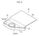
- the cover member according to the present invention may be one resin-molded into a shape integrally including the fuel tray 36, for example, like a cover member 160 shown in Fig. 6 .
- This case may permit the tray portion 36b to also serve as the extension portion 60b including the hang-down portion 66 and the protruded portion 62 and permit the fitting portion 36a to also serve as the fitting hole 63.
- the present invention provides a work machine capable of effectively protecting a battery from a fuel splashing during fuel filling.
- the work machine provided by the present invention includes a fuel tank having a fuel-filler portion, a battery disposed near the fuel-filler portion, and a cover member.
- the cover member has a cover portion which covers an upper surface of the battery and an extension portion which continuously extends from the cover portion toward the fuel-filler portion to thereby cover a region from the battery to the fuel-filler portion.
- the extension portion includes a hang-down portion which hangs down from the cover portion to the fuel-filler portion side.
- the fuel can be received by the extension portion of the cover member.
- the fuel is thus prevented not only from adherence to the battery but also from widely splashing.
- the hang-down portion can prevent the fuel from flowing to a battery side and further effectively protect the battery from the fuel by directing the fuel adhered to the hang-down portion away from the battery.
- the cover member is formed of a sheet-shaped member capable of having a deflection in a thickness direction of the cover member; and the cover portion is supported in a cantilever manner over the battery at an edge part of the cover portion on the extension portion side and is deformable so as to be turned up to expose the upper surface of the battery.
- an operator can access the upper surface of the battery only by turning over the cover portion at the time of maintenance and the like.
- the cover portion is supported at only a single position of the edge part of the cover portion on the extension portion side to be deformable so as to make the supported portion be a crest. This support restrains the cover portion from having a recess to suppress accumulation of the fuel in the recess.
- the extension portion preferably has a fitting hole into which the fuel-filler portion is fitted. This fit enables the cover member including the extension portion to be stably supported, allowing the number of members for supporting the cover member and the number of work processes for mounting the cover member to be reduced.
- the work machine further includes a fuel tray which fits with the fuel-filler portion and the extension portion is supported by the fuel-filler portion while being pressed down by the fuel tray.
- This arrangement enables the cover member to be supported more stably by effective utilization of the fuel tray.
- the combination of the fuel tray and the cover member makes it possible to more effectively prevent the fuel from being dropped out during fuel filling.
- the cover member may be formed of a sheet-shaped member capable of having a deflection in a thickness direction of the cover member and the fuel tray presses down the extension portion to a position lower than the cover portion to thereby form the hang-down portion in the extension portion.
- the work machine includes a fuel tank having a fuel-filler portion, a battery arranged near the fuel-filler portion, and a cover member.
- the cover member has a cover portion which covers an upper surface of the battery and an extension portion which continuously extends from the cover portion toward the fuel-filler portion to cover a region from the battery to the fuel-filler portion.
Landscapes
- Engineering & Computer Science (AREA)
- Chemical & Material Sciences (AREA)
- Mechanical Engineering (AREA)
- Mining & Mineral Resources (AREA)
- Civil Engineering (AREA)
- General Engineering & Computer Science (AREA)
- Structural Engineering (AREA)
- Chemical Kinetics & Catalysis (AREA)
- General Chemical & Material Sciences (AREA)
- Electrochemistry (AREA)
- Sustainable Energy (AREA)
- Transportation (AREA)
- Combustion & Propulsion (AREA)
- Sustainable Development (AREA)
- Life Sciences & Earth Sciences (AREA)
- Aviation & Aerospace Engineering (AREA)
- Cooling, Air Intake And Gas Exhaust, And Fuel Tank Arrangements In Propulsion Units (AREA)
- Component Parts Of Construction Machinery (AREA)
- Battery Mounting, Suspending (AREA)
Abstract
Description
- The present invention relates to a work machine such as a hydraulic excavator, the work machine including a battery.
- In recent years, miniaturization of a work machine is being advanced. This requires various devices such as an engine and a fuel tank that are mounted on the work machine to be arranged closely to each other within a limited space. This arrangement can generate a case of locating the battery near a fuel-filler portion of the fuel tank at a high position. The battery has an upper surface, on which an electric component such as a connection terminal is exposed.
- For example, Japanese Patent Application Laid-open No.
2002-356874 - The upper surface of the battery, however, is not always allowed to be located above the fuel-filler portion. Besides, there is a requirement for preventing dusts from adherence to the upper surface of the battery. For this reason, the upper surface of the battery is conventionally covered with a protection cover.
- For example, Japanese Patent Application Laid-open No.
2004-152524 - The cover body is attached to the battery. The battery has a pair of supporting rods protruding upward beyond longitudinally opposite ends of the upper surface of the battery, respectively. The cover body is attached to the supporting rods with screw members. Specifically, the upper wall portion of the cover body has respective through-holes corresponding to the supporting rods, and the screw members are screwed into upper ends of the supporting rods through the through-holes. The upper wall portion is thus sandwiched between the screw members and the supporting rods.
- The battery protection cover, which covers the vertical surface of the battery with the hang-down portion thereof, can effectively protect the vertical surface of the battery from splashing fuel and the like; however, oil and the like is permitted to splash to a periphery of the battery. Hence, in the case of locating the battery not on the floor but at a high position, there is a risk of permitting oil and the like to splash to the periphery of the battery to stain a wide region.
- An object of the present invention is to provide a work machine capable of effectively protecting a battery from a fuel splashing during fuel filling. The work machine provided by the present invention includes a fuel tank having a fuel-filler portion, a battery disposed near the fuel-filler portion, and a cover member. The cover member has a cover portion which covers an upper surface of the battery and an extension portion which continuously extends from the cover portion toward the fuel-filler portion to thereby cover a region from the battery to the fuel-filler portion. The extension portion includes a hang-down portion which hangs down from the cover portion to the fuel-filler portion side.
-
-
Fig. 1 is a side view of a work machine according to an embodiment of the present invention; -
Fig. 2 is a perspective view partially showing the work machine; -
Fig. 3 is a perspective view partially showing a relevant part of the work machine; -
Fig. 4 is an exploded perspective view of a relevant part of the work machine; -
Fig. 5 is a front view of a relevant part of the work machine; and -
Fig. 6 is a perspective view of a relevant part of a work machine according to a modification. - An embodiment of the present invention is described in detail below with reference to the drawings. The following description is, however, basically exemplary, thus not limiting the present invention, an application thereof, or a usage thereof.
-
Figs. 1 and2 show ahydraulic excavator 1 as an example of a work machine according to the present invention. Thehydraulic excavator 1 is a backward small-slew type compact machine, including a crawler-type lower crawlingbody 2, anupper slewing body 3 slewably mounted on the crawler-type lower crawlingbody 2, and anattachment 10. - The
upper slewing body 3 includes afirst machine room 4, asecond machine room 5, ahood 7, and acounterweight 8. Thefirst machine room 4 forms a right-side portion of theupper slewing body 3, and accommodates elements of thehydraulic excavator 1, namely, afuel tank 30, ahydraulic fluid tank 9, abattery 50, and the like. Thesecond machine room 5 forms a rear-side portion of theupper slewing body 3 and houses an engine and the like. Theupper slewing body 3 is formed with anoperation space 6 at a left-side portion thereof, in which an operating seat, an operation lever, and the like are provided. Thehood 7 is located at an upper side of theoperation space 6 to cover theoperation space 6. - The
upper slewing body 3 includes abottom plate 3a, a pair ofvertical plates 3b, and afront bracket 3c shown inFigs. 1 and3 . Thebottom plate 3a forms a lower-side portion of theupper slewing body 3, being supported by the lowercrawling body 2 via a slew bearing 2a so as to be slewable. The first andsecond machine rooms bottom plate 3a. The pair ofvertical plates 3b stand up on thebottom plate 3a and extend in a front-and-back direction while being separated from each other in a right-and-left direction. Thefront bracket 3c is fixed to respective front end portions of both thevertical plates 3b. - Unless otherwise specified, an up-and-down direction, a front-and-back direction, and a right-and-left direction in the following description are all based on the
upper slewing body 3 as shown inFig. 1 and others. - The
attachment 10 is supported by a front-side portion of theupper slewing body 3 so as to be swingable around a horizontal axis HJ and a vertical axis VJ shown inFig. 1 . Theattachment 10 includes: abucket 11; anarm 12; aboom 13; a plurality of hydraulically-controlled hydraulic cylinders, namely, abucket cylinder 14a, anarm cylinder 14b, aboom cylinder 14c, and aswing cylinder 14d; and aswing bracket 15. Thebucket 11 is supported by a front portion of thearm 12 to be swung by the expansion and contraction of thebucket cylinder 14a. Thearm 12 has a basal end portion, which is supported by a front end portion of theboom 13. Thearm 12 is swung by the expansion and contraction of thearm cylinder 14b. Theboom 13 has a base end portion, which is supported by theswing bracket 15. Theboom 13 is swung around the horizontal axis HJ by the expansion and contraction of theboom cylinder 14c. Theswing bracket 15 is supported by thefront bracket 3c to be swung around the vertical axis VJ by the expansion and contraction of theswing cylinder 14d, as shown inFig. 2 . The thus designedattachment 10 is actuated in an up-and-down direction and a right-and-left direction according to an operation applied to an operation lever and the like. Thecounterweight 8 is disposed in a rear portion of theupper slewing body 3 to keep a balance in a front-and-back direction relative to the thus actuatedattachment 10. - The
fuel tank 30 is a container to store the fuel for driving the engine. Thefuel tank 30 is formed of, for example, a synthetic resin to have a shape including concavities and convexities as shown inFig. 3 . Thefuel tank 30 is disposed in a front-side portion of thefirst machine room 4 as a side machine room. Thefuel tank 30 has amain body portion 30a and anupper extension portion 30b. Theupper extension portion 30b extends upward from a part of a region (a right-side region in the embodiment) of thebody portion 30a. - The
hydraulic fluid tank 9 is a container to store hydraulic fluid used for hydraulic control. Thehydraulic fluid tank 9 has, for example, a rectangular shape. Thehydraulic fluid tank 9 is disposed adjacently to the rear side of thefuel tank 30. - The
battery 50 is disposed above and across over thebody portion 30a of thefuel tank 30 in a front-and-back direction. In other words, thebattery 50 is adjacent to thefuel tank 30. Specifically, thebattery 50 according to the present embodiment is adjacent to thebody portion 30a of thefuel tank 30 at the upper side of thebody portion 30a, and is adjacent to theupper extension portion 30b at the lateral side of theupper extension portion 30b. - The
fuel tank 30 is installed on a base 31 mounted on thebottom plate 3a. Thebattery 50 is mounted on thebase 31 via avertical pillar 32 and abattery tray 33. Thevertical pillar 32 extends upward from a front end of thebase 31. Thebattery tray 33 is connected to an upper end portion of thevertical pillar 32 to be located over thefuel tank 30. - The
battery 50 according to the present embodiment forms a laterally-long rectangular parallelepiped shape including anupper surface 50a, on which there are provided electric parts, such as a connection terminal, and an indicator for confirming liquid quantity of filling liquid. Thebattery 50 is put on thebattery tray 33 so as to extend in a front-and-back direction and fastened by afastener 34 shown inFigs. 4 and5 . - The
fastener 34 has apressing portion 34a, a pair ofarms 34b, and anut member 34c as supporting members. Thepressing portion 34a is placed on the upper surface of thebattery 50 mounted on thebattery tray 33. Thepressing portion 34a has a slender shape across over thebattery 50 in a right-and-left width direction. Each of the pair ofarms 34b extends upward from thebattery tray 33 and has an upper end portion. Respective upper end portions of thearms 34b and both end portions of thepressing portion 34a are fastened together, respectively to thereby cause thepressing portion 34a to press thebattery 50 downward. Thebattery tray 33 has a pair of right and left engagingholes 33a. Each of thearms 34b has a lower end formed with a hook. Thepressing portion 34a is fastened to an upper end of eacharm 34b while the hooks are engaged with respective engagingholes 33a, thereby fixing thebattery 50 to thebattery tray 33. - The
fuel tank 30 has a fuel-filler portion 35, which protrudes upward beyond the upper surface of theupper extension portion 30b, and, for example, has a cylindrical shape. Thehydraulic excavator 1 further includes afuel tray 36, which is disposed around the fuel-filler portion 35. The fuel-filler portion 35 is located near thebattery 50, specifically, near a right-side surface of thebattery 50, the right-side surface extending in a front-and-back direction. The fuel-filler portion 35 has alower end 35a and anupper end 35b shown inFig. 5 . Thelower end 35a is below theupper surface 50a of thebattery 50. Theupper end 35b is above theupper surface 50a of thebattery 50. - The
hydraulic excavator 1 further includes acover sheet 60 as a cover member. Thecover sheet 60 is laid over thebattery 50 to prevent the fuel from splashing to theupper surface 50a of thebattery 50 during fuel filling. - The
cover sheet 60 is a flexible sheet-shaped member capable of having a deflection in a thickness direction of thecover sheet 60. Thecover sheet 60 is formed of a material excellent in oil-resistance and electric insulation characteristics, for example, rubber or a synthetic resin. Thecover sheet 60 is processed into such a shape and disposed in such a state as to improve convenience at a maintenance time of thebattery 50 and improve the protection performance for theupper surface 50a of thebattery 50. - Specifically, as shown in
Fig. 4 , thecover sheet 60 has acover portion 60a and anextension portion 60b as shown inFig. 4 . Thecover portion 60a is a portion which covers theupper surface 50a of thebattery 50. Thecover portion 60a is formed in a rectangular shape larger than theupper surface 50a of thebattery 50. Theextension portion 60b is a portion which extends from thecover portion 60a toward the fuel-filler portion 35 to cover a region from theupper surface 50a of thebattery 50 to a peripheral portion of the fuel-filler portion 35. Theextension portion 60b according to the present embodiment has approximately a trapezoidal shape, whose side corresponding to a lower bottom of the trapezoid, that is, an end portion of a long-side side, is continuous with one of the long-sides of thecover portion 60a. - The
cover portion 60a has afastening hole 61, which is formed in an edge part of thecover portion 60a on the side near theextension portion 60b. Thefastening hole 61 is formed in a portion intermediate longitudinally of the edge part. This intermediate portion is a center portion of theentire cover sheet 60. - The
extension portion 60b has afitting hole 63. Thefitting hole 63 is formed in a part of theextension portion 60b, which part is separated from thecover portion 60a and constitutes a protrudedportion 62 in a fitting state described later. - The
cover sheet 60 is disposed in such a posture that theextension portion 60b extends from thecover portion 60a toward the fuel-filler portion 35. In this state, afitting bolt 64 as a fastening member is inserted into thefastening hole 61 and fastened with thenut member 34c, thereby allowing thenut member 34c to support thecover portion 60a. - Specifically, the
nut member 34c extends upward from an end portion on the side of the fuel-filler portion 35 of thepressing portion 34a at a position corresponding to a position of thefastening hole 61. Thenut member 34c has an upper end portion, which is located at a height approximately equivalent to a height of theupper end 35b of the fuel-filler portion 35 and above theupper surface 50a of thebattery 50. - Preferably are provided
washer members 65 for leakage prevention above and below thefastening hole 61, respectively. In this case, thefitting bolt 64 inserted into thefastening hole 61 is fastened to an upper end of thenut member 34c so as to hold the leakageprevention washer members 65 axially between thefitting bolt 64 and thenut member 34c. Thecover portion 60a is thereby supported in a cantilever manner by thenut member 34c at a single point (hereinafter, also referred to as a support point S) in an edge part on the fuel-filler-portion-35 side of thecover portion 60a and over theupper surface 50a of thebattery 50. The other edge part of thecover portion 60a is a free end. - The
cover portion 60a supported at the support point S covers theupper surface 50a of thebattery 50 while having a shape of hanging down from the support point S as a crest. Thecover portion 60a, thus supported at the single support point S located at an intermediate portion of a long edge part of thecover portion 60a to have a shape of hanging down while flared, hardly has a recess. Hence, even when adhered to thecover portion 60a, the fuel can be smoothly removed before accumulated on thecover portion 60a. - In addition, the flexibility of the
cover sheet 60 improves maintenance workability of thebattery 50. Specifically, at the time of performing periodical maintenance of thebattery 50 such as confirmation of the indicator, an operator can access theupper surface 50a of thebattery 50 by only turning over thecover portion 60a while letting thefitting bolt 64 remain mounted on thenut member 34c. It is, therefore, unnecessary to detach thefitting bolt 64 at each maintenance time of thebattery 50. Also, the fuel can be prevented from entering theupper surface 50a of thebattery 50 through thefastening hole 61 at the detach work. - On the other hand, the
fitting hole 63 has a diameter permitting the fuel-filler portion 35 to pierce through theextension portion 60b while the fuel-filler portion 35 is being fitted into thefitting hole 63. Thefuel tray 36 is to be placed on theextension portion 60b while being fitted with the fuel-filler portion 35 protruding upward through thefitting hole 63, thereby pressing theextension portion 60b downward. Thefuel tray 36 has a cylindricalfitting portion 36a into which the fuel-filler portion 35 can be fitted, and atray portion 36b extending outward from a lower end of thefitting portion 36a. Thetray portion 36b is provided with a discharging outlet not shown for discharging the fuel that is accumulated on thetray portion 36b. - The
extension portion 60b is positioned over thefuel tank 30 by the fit of the fuel-filler portion 35 into thefitting hole 63. Thefuel tray 36 is disposed around the fuel-filler portion 35 by fitting an upward protruding part of the fuel-filler portion 35 beyond theextension portion 60b into thefitting portion 36a, and presses theextension portion 60b downward to cause theextension portion 60b to be supported by the fuel-filler portion 35. Theextension portion 60b, thus being pressed down by thefuel tray 36 to a position lower than the support point S and thecover portion 60a supported at the support point S as shown inFig. 4 , is deformed into a shape having a hang-down portion 66 which hangs down from thecover portion 60a to the fuel-filler portion 35 side, and the protrudedportion 62 protruded from the hang-down portion 66 to the fuel-filler portion 35 side. - This shape of the
cover sheet 60 prevents the fuel having leaked outside thefuel tray 36 during fuel filling from flowing into theupper surface 50a of thebattery 50. Specifically, the hang-down portion 66 directs the fuel to a side away from theupper surface 50a of thebattery 50 to thereby protect thebattery 50 from the fuel effectively even though thebattery 50 is disposed near the fuel-filler portion 35. Furthermore, theextension portion 60b, covering the region from thebattery 50 to the fuel-filler portion 35, can effectively prevent the fuel splashing beyond thefuel tray 36 during fuel filling from entering into a gap between thefuel tank 30 and thebattery 50 or splashing to a periphery of the gap. In addition, the fit of the fuel-filler portion 35 into thefitting hole 63 enables thecover sheet 60 to be stably supported. This allows supporting members such as the fitting bolts to be reduced, thus contributing to reduction in cost of members and the number of work processes. - The work machine according to the present invention is not limited to the above embodiment, but can include other various modes.
- For example, the
cover sheet 60 is an example of the cover member according to the present invention, whose shape and material can be suitably changed according to specifications. Thecover sheet 60 may be integrated with thefuel tray 36. The material of the cover member according to the present invention is not limited to flexible one like thecover sheet 60, but may be a resin-molded product with a higher rigidity than that of thecover sheet 60. For example, the cover member according to the present invention may have a shape including the hang-down portion and the protruded part also in a state before mounted. In this case, although the cover member is required to be detached when an operator will access theupper surface 50a of thebattery 50, an excellent workability is also secured because the detachment of theextension portion 60b is easy. Besides, making at least thecover portion 60a be transparent would allow the indicator to be confirmed at an upper side of the cover member, which improves maintenance workability. Furthermore, the cover member, if being a rigid resin-molded product, can be stably supported only by the fit of the extension portion with the fuel-filler portion, which may permit the support by the battery to be omitted. - The cover member according to the present invention may be one resin-molded into a shape integrally including the
fuel tray 36, for example, like a cover member 160 shown inFig. 6 . This case may permit thetray portion 36b to also serve as theextension portion 60b including the hang-down portion 66 and the protrudedportion 62 and permit thefitting portion 36a to also serve as thefitting hole 63. - As described above, the present invention provides a work machine capable of effectively protecting a battery from a fuel splashing during fuel filling. The work machine provided by the present invention includes a fuel tank having a fuel-filler portion, a battery disposed near the fuel-filler portion, and a cover member. The cover member has a cover portion which covers an upper surface of the battery and an extension portion which continuously extends from the cover portion toward the fuel-filler portion to thereby cover a region from the battery to the fuel-filler portion. The extension portion includes a hang-down portion which hangs down from the cover portion to the fuel-filler portion side.
- According to this work machine, even when dropped out around the fuel-filler portion during fuel filling, the fuel can be received by the extension portion of the cover member. The fuel is thus prevented not only from adherence to the battery but also from widely splashing. The hang-down portion can prevent the fuel from flowing to a battery side and further effectively protect the battery from the fuel by directing the fuel adhered to the hang-down portion away from the battery.
- Preferably, the cover member is formed of a sheet-shaped member capable of having a deflection in a thickness direction of the cover member; and the cover portion is supported in a cantilever manner over the battery at an edge part of the cover portion on the extension portion side and is deformable so as to be turned up to expose the upper surface of the battery.
- According to the cover member, an operator can access the upper surface of the battery only by turning over the cover portion at the time of maintenance and the like.
- More preferably, the cover portion is supported at only a single position of the edge part of the cover portion on the extension portion side to be deformable so as to make the supported portion be a crest. This support restrains the cover portion from having a recess to suppress accumulation of the fuel in the recess.
- On the other hand, the extension portion preferably has a fitting hole into which the fuel-filler portion is fitted. This fit enables the cover member including the extension portion to be stably supported, allowing the number of members for supporting the cover member and the number of work processes for mounting the cover member to be reduced.
- More preferably, the work machine further includes a fuel tray which fits with the fuel-filler portion and the extension portion is supported by the fuel-filler portion while being pressed down by the fuel tray. This arrangement enables the cover member to be supported more stably by effective utilization of the fuel tray. Besides, the combination of the fuel tray and the cover member makes it possible to more effectively prevent the fuel from being dropped out during fuel filling.
- In this case, the cover member may be formed of a sheet-shaped member capable of having a deflection in a thickness direction of the cover member and the fuel tray presses down the extension portion to a position lower than the cover portion to thereby form the hang-down portion in the extension portion.
- This application is based on Japanese Patent application No.
2013-076810
Although the present invention has been fully described by way of example with reference to the accompanying drawings, it is to be understood that various changes and modifications will be apparent to those skilled in the art. Therefore, unless otherwise such changes and modifications depart from the scope of the present invention hereinafter defined, they should be construed as being included therein. - Provided is a work machine capable of protecting a battery from splashing fuel during fuel filling. The work machine includes a fuel tank having a fuel-filler portion, a battery arranged near the fuel-filler portion, and a cover member. The cover member has a cover portion which covers an upper surface of the battery and an extension portion which continuously extends from the cover portion toward the fuel-filler portion to cover a region from the battery to the fuel-filler portion.
Claims (6)
- A work machine comprising:a fuel tank having a fuel-filler portion;a battery disposed near the fuel-filler portion; anda cover member,wherein the cover member includes a cover portion which covers an upper surface of the battery and an extension portion which continuously extends from the cover portion toward the fuel-filler portion to thereby cover a region from the battery to the fuel-filler portion, the extension portion including a hang-down portion which hangs down from the cover portion to the fuel-filler portion side.
- The work machine according to claim 1, wherein the cover member is formed of a sheet-shaped member capable of having a deflection in a thickness direction of the cover member; and the cover portion is supported in a cantilever manner over the battery at an edge part of the cover portion on the extension portion side and is deformable so as to be turned up to expose the upper surface of the battery.
- The work machine according to claim 2, wherein the cover portion is supported at only a single position of the edge part of the cover portion on the extension portion side to be deformable so as to make the supported portion be highest in the cover portion.
- The work machine according to any of claims 1 to 3, wherein the extension portion has a fitting hole into which the fuel-filler portion is fitted.
- The work machine according to claim 4, further comprising a fuel tray which fits with the fuel-filler portion, wherein the extension portion is supported by the fuel-filler portion while being pressed down by the fuel tray.
- The work machine according to claim 5, wherein the cover member is formed of a sheet-shaped member capable of having a deflection in a thickness direction of the cover member and the fuel tray presses down the extension portion to a position lower than the cover portion to thereby form the hang-down portion in the extension portion.
Applications Claiming Priority (1)
| Application Number | Priority Date | Filing Date | Title |
|---|---|---|---|
| JP2013076810A JP5761245B2 (en) | 2013-04-02 | 2013-04-02 | Work machine |
Publications (3)
| Publication Number | Publication Date |
|---|---|
| EP2787124A2 true EP2787124A2 (en) | 2014-10-08 |
| EP2787124A3 EP2787124A3 (en) | 2018-03-28 |
| EP2787124B1 EP2787124B1 (en) | 2019-12-04 |
Family
ID=50272482
Family Applications (1)
| Application Number | Title | Priority Date | Filing Date |
|---|---|---|---|
| EP14159731.0A Active EP2787124B1 (en) | 2013-04-02 | 2014-03-14 | Work machine including battery |
Country Status (5)
| Country | Link |
|---|---|
| US (1) | US9067490B2 (en) |
| EP (1) | EP2787124B1 (en) |
| JP (1) | JP5761245B2 (en) |
| KR (1) | KR102103033B1 (en) |
| CN (1) | CN104099967B (en) |
Families Citing this family (11)
| Publication number | Priority date | Publication date | Assignee | Title |
|---|---|---|---|---|
| JP5546484B2 (en) * | 2011-03-17 | 2014-07-09 | 日立建機株式会社 | Mini excavator fuel tank fixing structure |
| JP6028588B2 (en) * | 2013-01-22 | 2016-11-16 | コベルコ建機株式会社 | Work machine |
| JP5761245B2 (en) * | 2013-04-02 | 2015-08-12 | コベルコ建機株式会社 | Work machine |
| JP6495082B2 (en) * | 2015-04-17 | 2019-04-03 | 日立建機株式会社 | Construction machinery |
| CN105161642A (en) * | 2015-07-16 | 2015-12-16 | 柳州首光科技有限公司 | Battery protection device of power mechanical device |
| JP6358278B2 (en) * | 2016-03-11 | 2018-07-18 | コベルコ建機株式会社 | Work machine |
| EP3436323A1 (en) * | 2016-04-01 | 2019-02-06 | Agility Fuel Systems LLC | Vehicle fluid handling systems |
| US10184227B2 (en) * | 2016-06-21 | 2019-01-22 | Kubota Corporation | Work machine |
| US11440399B2 (en) | 2019-03-22 | 2022-09-13 | Agility Fuel Systems Llc | Fuel system mountable to a vehicle frame |
| US20200347992A1 (en) | 2019-05-02 | 2020-11-05 | Agility Fuel Systems Llc | Polymeric liner based gas cylinder with reduced permeability |
| JP2025006873A (en) * | 2023-06-30 | 2025-01-17 | 株式会社クボタ | Work equipment |
Family Cites Families (17)
| Publication number | Priority date | Publication date | Assignee | Title |
|---|---|---|---|---|
| US4013300A (en) * | 1975-08-18 | 1977-03-22 | Berger Allan H | Fuel tank and battery combination structure |
| JP3393988B2 (en) * | 1998-03-23 | 2003-04-07 | 株式会社クボタ | Revolving work machine tank device |
| JP2001279719A (en) * | 2000-03-31 | 2001-10-10 | Kobelco Contstruction Machinery Ltd | Small type hydraulic shovel |
| JP2002356874A (en) | 2001-06-04 | 2002-12-13 | Shin Caterpillar Mitsubishi Ltd | Hydraulic backhoe |
| JP3945698B2 (en) * | 2002-10-23 | 2007-07-18 | ヤンマー農機株式会社 | Tracked tractor |
| JP2004152524A (en) * | 2002-10-29 | 2004-05-27 | Komatsu Ltd | Battery protection cover |
| JP4093474B2 (en) * | 2003-04-24 | 2008-06-04 | 新キャタピラー三菱株式会社 | Construction machinery |
| JP2005041316A (en) * | 2003-07-28 | 2005-02-17 | Hitachi Constr Mach Co Ltd | Construction machine |
| JP4515232B2 (en) * | 2004-11-22 | 2010-07-28 | 株式会社クボタ | Swivel work machine |
| JP2007090953A (en) * | 2005-09-27 | 2007-04-12 | Ishikawajima Constr Mach Co | Fuel supply port and cover structure for work machine |
| JP4913512B2 (en) * | 2006-09-19 | 2012-04-11 | ヤンマー株式会社 | Work vehicle |
| JP4840294B2 (en) * | 2007-08-30 | 2011-12-21 | コベルコ建機株式会社 | Construction machinery |
| JP2009243118A (en) * | 2008-03-31 | 2009-10-22 | Kubota Corp | Backhoe |
| WO2011136107A1 (en) * | 2010-04-26 | 2011-11-03 | 日立建機株式会社 | Construction machine |
| JP5562777B2 (en) * | 2010-09-16 | 2014-07-30 | 日立建機株式会社 | Construction machinery |
| KR101562698B1 (en) * | 2012-07-27 | 2015-10-30 | 가부시끼 가이샤 구보다 | Body structure of work vehicle |
| JP5761245B2 (en) * | 2013-04-02 | 2015-08-12 | コベルコ建機株式会社 | Work machine |
-
2013
- 2013-04-02 JP JP2013076810A patent/JP5761245B2/en active Active
-
2014
- 2014-03-14 US US14/211,548 patent/US9067490B2/en active Active
- 2014-03-14 EP EP14159731.0A patent/EP2787124B1/en active Active
- 2014-03-28 KR KR1020140036928A patent/KR102103033B1/en not_active Expired - Fee Related
- 2014-04-02 CN CN201410131619.6A patent/CN104099967B/en not_active Expired - Fee Related
Also Published As
| Publication number | Publication date |
|---|---|
| US20140291047A1 (en) | 2014-10-02 |
| EP2787124B1 (en) | 2019-12-04 |
| KR20140120271A (en) | 2014-10-13 |
| CN104099967A (en) | 2014-10-15 |
| EP2787124A3 (en) | 2018-03-28 |
| KR102103033B1 (en) | 2020-04-21 |
| JP2014201902A (en) | 2014-10-27 |
| US9067490B2 (en) | 2015-06-30 |
| CN104099967B (en) | 2017-09-15 |
| JP5761245B2 (en) | 2015-08-12 |
Similar Documents
| Publication | Publication Date | Title |
|---|---|---|
| US9067490B2 (en) | Work machine including battery | |
| US8950538B2 (en) | Working machine | |
| EP1462579B1 (en) | Hydraulic shovel with counterweight | |
| EP2199471B1 (en) | Construction machine | |
| EP2960380B1 (en) | Construction machine | |
| JP5212441B2 (en) | Work machine fuel tank mounting device | |
| US20150129558A1 (en) | Wire electric discharge machining apparatus | |
| EP2687635A1 (en) | Hydraulic oil tank attachment structure of construction machine | |
| EP2428617B1 (en) | Pillar structure for construction machine | |
| EP2378007B1 (en) | Working machine with equipment room | |
| JP5387665B2 (en) | Work machine | |
| US20150216060A1 (en) | Monitor and Working Vehicle Provided with the Monitor | |
| US8382198B2 (en) | Device removing/re-inserting structure, and device removing/re-inserting method for construction machine | |
| EP2876218A1 (en) | Construction machine including air cleaner | |
| US20150159345A1 (en) | Construction machine | |
| JP5087916B2 (en) | Engine balancer equipment | |
| EP2868810A1 (en) | Construction machine | |
| JP5733290B2 (en) | Hydraulic oil tank device | |
| KR20120011566A (en) | Driver seat support for construction machinery | |
| JP4486450B2 (en) | Work machine | |
| CN105161642A (en) | Battery protection device of power mechanical device | |
| JP6156130B2 (en) | Construction machinery | |
| KR20150027353A (en) | Side View Camera Mounting Structure For Construction Machine | |
| JP2012075447A (en) | Sewing machine under-cover and sewing machine | |
| KR20120008978A (en) | Shatterproof devices |
Legal Events
| Date | Code | Title | Description |
|---|---|---|---|
| PUAI | Public reference made under article 153(3) epc to a published international application that has entered the european phase |
Free format text: ORIGINAL CODE: 0009012 |
|
| 17P | Request for examination filed |
Effective date: 20140314 |
|
| AK | Designated contracting states |
Kind code of ref document: A2 Designated state(s): AL AT BE BG CH CY CZ DE DK EE ES FI FR GB GR HR HU IE IS IT LI LT LU LV MC MK MT NL NO PL PT RO RS SE SI SK SM TR |
|
| AX | Request for extension of the european patent |
Extension state: BA ME |
|
| PUAL | Search report despatched |
Free format text: ORIGINAL CODE: 0009013 |
|
| AK | Designated contracting states |
Kind code of ref document: A3 Designated state(s): AL AT BE BG CH CY CZ DE DK EE ES FI FR GB GR HR HU IE IS IT LI LT LU LV MC MK MT NL NO PL PT RO RS SE SI SK SM TR |
|
| AX | Request for extension of the european patent |
Extension state: BA ME |
|
| RIC1 | Information provided on ipc code assigned before grant |
Ipc: H01M 2/10 20060101ALI20180217BHEP Ipc: E02F 9/08 20060101ALI20180217BHEP Ipc: H01M 2/02 20060101ALI20180217BHEP Ipc: B60K 15/077 20060101ALI20180217BHEP Ipc: E02F 3/32 20060101AFI20180217BHEP Ipc: B60R 16/04 20060101ALI20180217BHEP Ipc: B60K 15/03 20060101ALI20180217BHEP |
|
| STAA | Information on the status of an ep patent application or granted ep patent |
Free format text: STATUS: REQUEST FOR EXAMINATION WAS MADE |
|
| R17P | Request for examination filed (corrected) |
Effective date: 20180725 |
|
| RBV | Designated contracting states (corrected) |
Designated state(s): AL AT BE BG CH CY CZ DE DK EE ES FI FR GB GR HR HU IE IS IT LI LT LU LV MC MK MT NL NO PL PT RO RS SE SI SK SM TR |
|
| STAA | Information on the status of an ep patent application or granted ep patent |
Free format text: STATUS: EXAMINATION IS IN PROGRESS |
|
| 17Q | First examination report despatched |
Effective date: 20181128 |
|
| GRAP | Despatch of communication of intention to grant a patent |
Free format text: ORIGINAL CODE: EPIDOSNIGR1 |
|
| STAA | Information on the status of an ep patent application or granted ep patent |
Free format text: STATUS: GRANT OF PATENT IS INTENDED |
|
| RIC1 | Information provided on ipc code assigned before grant |
Ipc: B60K 15/077 20060101ALI20190515BHEP Ipc: E02F 9/08 20060101ALI20190515BHEP Ipc: E02F 3/32 20060101AFI20190515BHEP Ipc: B60K 15/063 20060101ALI20190515BHEP Ipc: B60R 16/04 20060101ALI20190515BHEP Ipc: B60K 15/03 20060101ALI20190515BHEP Ipc: H01M 2/02 20060101ALI20190515BHEP Ipc: H01M 2/10 20060101ALI20190515BHEP |
|
| INTG | Intention to grant announced |
Effective date: 20190619 |
|
| GRAS | Grant fee paid |
Free format text: ORIGINAL CODE: EPIDOSNIGR3 |
|
| GRAA | (expected) grant |
Free format text: ORIGINAL CODE: 0009210 |
|
| STAA | Information on the status of an ep patent application or granted ep patent |
Free format text: STATUS: THE PATENT HAS BEEN GRANTED |
|
| AK | Designated contracting states |
Kind code of ref document: B1 Designated state(s): AL AT BE BG CH CY CZ DE DK EE ES FI FR GB GR HR HU IE IS IT LI LT LU LV MC MK MT NL NO PL PT RO RS SE SI SK SM TR |
|
| REG | Reference to a national code |
Ref country code: GB Ref legal event code: FG4D |
|
| REG | Reference to a national code |
Ref country code: CH Ref legal event code: EP |
|
| REG | Reference to a national code |
Ref country code: AT Ref legal event code: REF Ref document number: 1209553 Country of ref document: AT Kind code of ref document: T Effective date: 20191215 |
|
| REG | Reference to a national code |
Ref country code: DE Ref legal event code: R096 Ref document number: 602014057698 Country of ref document: DE |
|
| REG | Reference to a national code |
Ref country code: IE Ref legal event code: FG4D |
|
| REG | Reference to a national code |
Ref country code: NL Ref legal event code: MP Effective date: 20191204 |
|
| REG | Reference to a national code |
Ref country code: LT Ref legal event code: MG4D |
|
| PG25 | Lapsed in a contracting state [announced via postgrant information from national office to epo] |
Ref country code: GR Free format text: LAPSE BECAUSE OF FAILURE TO SUBMIT A TRANSLATION OF THE DESCRIPTION OR TO PAY THE FEE WITHIN THE PRESCRIBED TIME-LIMIT Effective date: 20200305 Ref country code: LT Free format text: LAPSE BECAUSE OF FAILURE TO SUBMIT A TRANSLATION OF THE DESCRIPTION OR TO PAY THE FEE WITHIN THE PRESCRIBED TIME-LIMIT Effective date: 20191204 Ref country code: FI Free format text: LAPSE BECAUSE OF FAILURE TO SUBMIT A TRANSLATION OF THE DESCRIPTION OR TO PAY THE FEE WITHIN THE PRESCRIBED TIME-LIMIT Effective date: 20191204 Ref country code: BG Free format text: LAPSE BECAUSE OF FAILURE TO SUBMIT A TRANSLATION OF THE DESCRIPTION OR TO PAY THE FEE WITHIN THE PRESCRIBED TIME-LIMIT Effective date: 20200304 Ref country code: LV Free format text: LAPSE BECAUSE OF FAILURE TO SUBMIT A TRANSLATION OF THE DESCRIPTION OR TO PAY THE FEE WITHIN THE PRESCRIBED TIME-LIMIT Effective date: 20191204 Ref country code: SE Free format text: LAPSE BECAUSE OF FAILURE TO SUBMIT A TRANSLATION OF THE DESCRIPTION OR TO PAY THE FEE WITHIN THE PRESCRIBED TIME-LIMIT Effective date: 20191204 Ref country code: NO Free format text: LAPSE BECAUSE OF FAILURE TO SUBMIT A TRANSLATION OF THE DESCRIPTION OR TO PAY THE FEE WITHIN THE PRESCRIBED TIME-LIMIT Effective date: 20200304 Ref country code: ES Free format text: LAPSE BECAUSE OF FAILURE TO SUBMIT A TRANSLATION OF THE DESCRIPTION OR TO PAY THE FEE WITHIN THE PRESCRIBED TIME-LIMIT Effective date: 20191204 |
|
| PG25 | Lapsed in a contracting state [announced via postgrant information from national office to epo] |
Ref country code: HR Free format text: LAPSE BECAUSE OF FAILURE TO SUBMIT A TRANSLATION OF THE DESCRIPTION OR TO PAY THE FEE WITHIN THE PRESCRIBED TIME-LIMIT Effective date: 20191204 Ref country code: RS Free format text: LAPSE BECAUSE OF FAILURE TO SUBMIT A TRANSLATION OF THE DESCRIPTION OR TO PAY THE FEE WITHIN THE PRESCRIBED TIME-LIMIT Effective date: 20191204 |
|
| PG25 | Lapsed in a contracting state [announced via postgrant information from national office to epo] |
Ref country code: AL Free format text: LAPSE BECAUSE OF FAILURE TO SUBMIT A TRANSLATION OF THE DESCRIPTION OR TO PAY THE FEE WITHIN THE PRESCRIBED TIME-LIMIT Effective date: 20191204 |
|
| PG25 | Lapsed in a contracting state [announced via postgrant information from national office to epo] |
Ref country code: NL Free format text: LAPSE BECAUSE OF FAILURE TO SUBMIT A TRANSLATION OF THE DESCRIPTION OR TO PAY THE FEE WITHIN THE PRESCRIBED TIME-LIMIT Effective date: 20191204 Ref country code: EE Free format text: LAPSE BECAUSE OF FAILURE TO SUBMIT A TRANSLATION OF THE DESCRIPTION OR TO PAY THE FEE WITHIN THE PRESCRIBED TIME-LIMIT Effective date: 20191204 Ref country code: PT Free format text: LAPSE BECAUSE OF FAILURE TO SUBMIT A TRANSLATION OF THE DESCRIPTION OR TO PAY THE FEE WITHIN THE PRESCRIBED TIME-LIMIT Effective date: 20200429 Ref country code: RO Free format text: LAPSE BECAUSE OF FAILURE TO SUBMIT A TRANSLATION OF THE DESCRIPTION OR TO PAY THE FEE WITHIN THE PRESCRIBED TIME-LIMIT Effective date: 20191204 Ref country code: CZ Free format text: LAPSE BECAUSE OF FAILURE TO SUBMIT A TRANSLATION OF THE DESCRIPTION OR TO PAY THE FEE WITHIN THE PRESCRIBED TIME-LIMIT Effective date: 20191204 |
|
| PG25 | Lapsed in a contracting state [announced via postgrant information from national office to epo] |
Ref country code: SM Free format text: LAPSE BECAUSE OF FAILURE TO SUBMIT A TRANSLATION OF THE DESCRIPTION OR TO PAY THE FEE WITHIN THE PRESCRIBED TIME-LIMIT Effective date: 20191204 Ref country code: SK Free format text: LAPSE BECAUSE OF FAILURE TO SUBMIT A TRANSLATION OF THE DESCRIPTION OR TO PAY THE FEE WITHIN THE PRESCRIBED TIME-LIMIT Effective date: 20191204 Ref country code: IS Free format text: LAPSE BECAUSE OF FAILURE TO SUBMIT A TRANSLATION OF THE DESCRIPTION OR TO PAY THE FEE WITHIN THE PRESCRIBED TIME-LIMIT Effective date: 20200404 |
|
| REG | Reference to a national code |
Ref country code: DE Ref legal event code: R097 Ref document number: 602014057698 Country of ref document: DE |
|
| REG | Reference to a national code |
Ref country code: AT Ref legal event code: MK05 Ref document number: 1209553 Country of ref document: AT Kind code of ref document: T Effective date: 20191204 |
|
| PLBE | No opposition filed within time limit |
Free format text: ORIGINAL CODE: 0009261 |
|
| STAA | Information on the status of an ep patent application or granted ep patent |
Free format text: STATUS: NO OPPOSITION FILED WITHIN TIME LIMIT |
|
| PG25 | Lapsed in a contracting state [announced via postgrant information from national office to epo] |
Ref country code: DK Free format text: LAPSE BECAUSE OF FAILURE TO SUBMIT A TRANSLATION OF THE DESCRIPTION OR TO PAY THE FEE WITHIN THE PRESCRIBED TIME-LIMIT Effective date: 20191204 Ref country code: MC Free format text: LAPSE BECAUSE OF FAILURE TO SUBMIT A TRANSLATION OF THE DESCRIPTION OR TO PAY THE FEE WITHIN THE PRESCRIBED TIME-LIMIT Effective date: 20191204 |
|
| REG | Reference to a national code |
Ref country code: CH Ref legal event code: PL |
|
| 26N | No opposition filed |
Effective date: 20200907 |
|
| PG25 | Lapsed in a contracting state [announced via postgrant information from national office to epo] |
Ref country code: AT Free format text: LAPSE BECAUSE OF FAILURE TO SUBMIT A TRANSLATION OF THE DESCRIPTION OR TO PAY THE FEE WITHIN THE PRESCRIBED TIME-LIMIT Effective date: 20191204 Ref country code: PL Free format text: LAPSE BECAUSE OF FAILURE TO SUBMIT A TRANSLATION OF THE DESCRIPTION OR TO PAY THE FEE WITHIN THE PRESCRIBED TIME-LIMIT Effective date: 20191204 Ref country code: SI Free format text: LAPSE BECAUSE OF FAILURE TO SUBMIT A TRANSLATION OF THE DESCRIPTION OR TO PAY THE FEE WITHIN THE PRESCRIBED TIME-LIMIT Effective date: 20191204 |
|
| REG | Reference to a national code |
Ref country code: BE Ref legal event code: MM Effective date: 20200331 |
|
| PG25 | Lapsed in a contracting state [announced via postgrant information from national office to epo] |
Ref country code: LU Free format text: LAPSE BECAUSE OF NON-PAYMENT OF DUE FEES Effective date: 20200314 |
|
| PG25 | Lapsed in a contracting state [announced via postgrant information from national office to epo] |
Ref country code: IE Free format text: LAPSE BECAUSE OF NON-PAYMENT OF DUE FEES Effective date: 20200314 Ref country code: LI Free format text: LAPSE BECAUSE OF NON-PAYMENT OF DUE FEES Effective date: 20200331 Ref country code: CH Free format text: LAPSE BECAUSE OF NON-PAYMENT OF DUE FEES Effective date: 20200331 |
|
| PG25 | Lapsed in a contracting state [announced via postgrant information from national office to epo] |
Ref country code: BE Free format text: LAPSE BECAUSE OF NON-PAYMENT OF DUE FEES Effective date: 20200331 |
|
| PG25 | Lapsed in a contracting state [announced via postgrant information from national office to epo] |
Ref country code: TR Free format text: LAPSE BECAUSE OF FAILURE TO SUBMIT A TRANSLATION OF THE DESCRIPTION OR TO PAY THE FEE WITHIN THE PRESCRIBED TIME-LIMIT Effective date: 20191204 Ref country code: MT Free format text: LAPSE BECAUSE OF FAILURE TO SUBMIT A TRANSLATION OF THE DESCRIPTION OR TO PAY THE FEE WITHIN THE PRESCRIBED TIME-LIMIT Effective date: 20191204 Ref country code: CY Free format text: LAPSE BECAUSE OF FAILURE TO SUBMIT A TRANSLATION OF THE DESCRIPTION OR TO PAY THE FEE WITHIN THE PRESCRIBED TIME-LIMIT Effective date: 20191204 |
|
| PG25 | Lapsed in a contracting state [announced via postgrant information from national office to epo] |
Ref country code: MK Free format text: LAPSE BECAUSE OF FAILURE TO SUBMIT A TRANSLATION OF THE DESCRIPTION OR TO PAY THE FEE WITHIN THE PRESCRIBED TIME-LIMIT Effective date: 20191204 |
|
| PGFP | Annual fee paid to national office [announced via postgrant information from national office to epo] |
Ref country code: FR Payment date: 20230208 Year of fee payment: 10 |
|
| PGFP | Annual fee paid to national office [announced via postgrant information from national office to epo] |
Ref country code: IT Payment date: 20230213 Year of fee payment: 10 Ref country code: GB Payment date: 20230202 Year of fee payment: 10 Ref country code: DE Payment date: 20230131 Year of fee payment: 10 |
|
| REG | Reference to a national code |
Ref country code: DE Ref legal event code: R119 Ref document number: 602014057698 Country of ref document: DE |
|
| GBPC | Gb: european patent ceased through non-payment of renewal fee |
Effective date: 20240314 |
|
| PG25 | Lapsed in a contracting state [announced via postgrant information from national office to epo] |
Ref country code: DE Free format text: LAPSE BECAUSE OF NON-PAYMENT OF DUE FEES Effective date: 20241001 |
|
| PG25 | Lapsed in a contracting state [announced via postgrant information from national office to epo] |
Ref country code: GB Free format text: LAPSE BECAUSE OF NON-PAYMENT OF DUE FEES Effective date: 20240314 |
|
| PG25 | Lapsed in a contracting state [announced via postgrant information from national office to epo] |
Ref country code: FR Free format text: LAPSE BECAUSE OF NON-PAYMENT OF DUE FEES Effective date: 20240331 |
|
| PG25 | Lapsed in a contracting state [announced via postgrant information from national office to epo] |
Ref country code: GB Free format text: LAPSE BECAUSE OF NON-PAYMENT OF DUE FEES Effective date: 20240314 Ref country code: FR Free format text: LAPSE BECAUSE OF NON-PAYMENT OF DUE FEES Effective date: 20240331 Ref country code: DE Free format text: LAPSE BECAUSE OF NON-PAYMENT OF DUE FEES Effective date: 20241001 |
|
| PG25 | Lapsed in a contracting state [announced via postgrant information from national office to epo] |
Ref country code: IT Free format text: LAPSE BECAUSE OF NON-PAYMENT OF DUE FEES Effective date: 20240314 |