EP2786951A1 - Door suspension and guiding arrangement for centrally opening panel doors, especially in elevators - Google Patents
Door suspension and guiding arrangement for centrally opening panel doors, especially in elevators Download PDFInfo
- Publication number
- EP2786951A1 EP2786951A1 EP13161956.1A EP13161956A EP2786951A1 EP 2786951 A1 EP2786951 A1 EP 2786951A1 EP 13161956 A EP13161956 A EP 13161956A EP 2786951 A1 EP2786951 A1 EP 2786951A1
- Authority
- EP
- European Patent Office
- Prior art keywords
- door
- panel
- guide
- guiding arrangement
- suspension
- Prior art date
- Legal status (The legal status is an assumption and is not a legal conclusion. Google has not performed a legal analysis and makes no representation as to the accuracy of the status listed.)
- Withdrawn
Links
- 239000000725 suspension Substances 0.000 title claims abstract description 46
- 238000010276 construction Methods 0.000 description 8
- 230000007246 mechanism Effects 0.000 description 4
- 238000007796 conventional method Methods 0.000 description 3
- 239000002184 metal Substances 0.000 description 3
- 229910000831 Steel Inorganic materials 0.000 description 2
- 239000010959 steel Substances 0.000 description 2
- 230000001360 synchronised effect Effects 0.000 description 2
- 230000000694 effects Effects 0.000 description 1
- 238000012986 modification Methods 0.000 description 1
- 230000004048 modification Effects 0.000 description 1
- 238000003466 welding Methods 0.000 description 1
Images




Classifications
-
- B—PERFORMING OPERATIONS; TRANSPORTING
- B66—HOISTING; LIFTING; HAULING
- B66B—ELEVATORS; ESCALATORS OR MOVING WALKWAYS
- B66B13/00—Doors, gates, or other apparatus controlling access to, or exit from, cages or lift well landings
- B66B13/02—Door or gate operation
- B66B13/06—Door or gate operation of sliding doors
- B66B13/08—Door or gate operation of sliding doors guided for horizontal movement
Definitions
- the present invention relates to a suspension and guiding arrangement for centrally opening panel doors for elevators.
- Elevators typically have a door both in the shaft doorway, which is called a landing door, to prevent falling into the shaft, as well as in the elevator car doorway to protect the passengers during elevator movement.
- the general structure of both doors is similar, i.e. they usually have the same opening configuration and the number of door panels. However, they can have differences for example in their locking mechanisms, fire-resistance and soundproofing properties.
- the door panels typically hang from a suspension and guiding arrangement comprising at least one guide rail attached to the door frame and, for each door panel, a panel guide and two or more wheels called guide rollers.
- the panel guide can vary in shape and be either continuous piece with the door panel, or be constructed from one or more separate pieces attached to the door panel.
- the guide rollers are attached either to the panel guide or to the guide rail and allow the movement of the door panel along the guide rail by rotating (as disclosed for example in the patent CH 365844 ).
- the typical arrangement of the guide rollers is that they are situated above the door panel near its each vertical edge and mounted on the panel guide. The distance between their rotational centers, called wheelbase, is slightly shorter than the width of the door panel.
- the guide rollers are accompanied by so-called anti-tip rollers that are mounted to the panel and roll, for example, along the underside of the guide rail or along its upper rim to balance the door.
- each panel has a cross member that contains a guide rail.
- Each cross member has an extension in the form of an arm, at the end of which there is a rotating roller which seats on the guide rail mounted to the door frame.
- the guide rail of the cross member moves on the stationary roller carried by the door frame during opening and closing of the door, whereas the rotating roller at the end of each cross member arm moves along the guide rail mounted to the door frame.
- An object of the present invention is to improve the door guiding properties of a door suspension and guiding arrangement for centrally opening automatic elevator doors. Another object is to improve the reliability and smoothness of the door function for centrally opening automatic elevator doors.
- centrally opening doors herein is meant doors that slide horizontally sideways, where the moving can be arranged in different ways, such as rollers, wheels or guide shoes moving on guide rails or guide rails moving on rollers, wheels or guide shoes.
- the centrally opening doors can also move using other mechanisms than the above-mentioned ones.
- the door suspension and guiding arrangement for centrally opening elevator doors presented here is characterized by comprising two or more door panels supported by a panel suspension and guiding arrangement so, that each door panel has a panel guide comprising at least two guide rollers which rollers allow the respective door panel to move in the direction of a guide rail between a closed and an open position of the door and in that the distance between the two guide rollers is greater than the width of the door panel to which they are attached, the at least two guide rollers are configured to move with the movement of the door panel and the distance between the at least two guide rollers is substantially the same in all positions of the door panel.
- an elevator comprising an elevator shaft, an elevator car arranged to move within the elevator shaft, an elevator car door and two or more landing doors, characterized in that a door suspension and guiding arrangement according is used in at least one of said doors.
- the door suspension and guiding arrangement can be utilized in both landing doors and elevator car doors, as the need for improved guiding exists in both.
- the panel guide is attached to the door panel or is an integral part of the door panel.
- the door panel is supported by guide rollers.
- the distance between the two guide rollers is exactly the same in all positions of the door panel.
- the guide rollers are configured to move within or on top of the guide rail.
- each door panel has two guide rollers located substantially at opposite ends of the panel guide.
- At least one anti-tip roller is included in the panel guide.
- each panel guide has its own guide rail.
- At least some of the door panels opening to the left use a common guide rail and at least some of the door panels opening to the right use a another common guide rail.
- each door panel is supported by two guide rails so, that all the guide rollers closest to the vertical center line of doorway when the door is open use a common guide rail and the other guide rollers use a second common guide rail.
- the door suspension and guiding arrangement is used in a landing door.
- the door suspension and guiding arrangement is used in an elevator car door.
- Fig. 1 presents a door suspension and guiding arrangement 3 of an elevator door in which the door comprises two door panels 1, 2 and each of them moves along its own guide rail 8, 9.
- the guide rails 8, 9 are mounted either to the door frame or to the elevator car.
- the guide rails 8, 9 are drawn to be vertically stacked. They could alternatively be on the same vertical level, one behind the other.
- Each door panel has two guide rollers 4, 5; 6, 7 attached to a panel guide 16, 17.
- the guide roller 4, 5, 6, 7 is a wheel, ball or other round element known in the field for such a structure.
- Each panel guide 16, 17 has the form of an arm attached vertically above the door panel 1, 2.
- Fig. 1 presents only a generalized overview of its structure.
- the panel guide 16, 17 could be extended from its other end.
- each panel guide 16, 17 is attached to the respective door panel 1, 2 over the entire width of the door panel 1, 2.
- the panel guide 16, 17 could be attached to the respective door panel 1, 2 over a shorter distance (than the whole width of the door panel) or could be attached at certain points (e.g. through welding or other fastening).
- Door panel 1 opens to the left along guide rail 9 with the assistance of guide rollers 6 and 7.
- Door panel 2 opens to the right along guide rail 8 with the assistance of guide rollers 4 and 5.
- the wheelbase of the guide rollers (i.e. the distance between the rotational centers of the guide rollers) of each door panel is approximately three times the width of the door panel, but also shorter and longer wheelbases can be used. In Fig.
- the guide rails 8 and 9 are drawn to be continuous, but when the wheelbase of the guide rollers 4 and 5, and 6 and 7, respectively, exceeds the distance moved by the door panel during opening and closing of the door, the guide rails 8 and 9 can be made discontinuous by omitting the parts which are not used by any of the guide rollers 4, 5, 6 and 7. In the embodiment of Fig. 1 , this would cover almost the whole width of the doorway (indicated by the grey bar at the top of Fig. 1 ). This alternative would reduce the weight of the door suspension and guiding arrangement and further stabilize the construction. In this view, door panel 1 is partly behind door panel 2 (indicated by the dashed outline). Any conventional actuator can be used to move the door panels 1, 2 and is not included in the drawing.
- the door arrangement can contain additional safety, automation or other devices which are omitted from this drawing.
- the bottom part of the door frame or elevator car comprises a guiding groove 12.
- At the bottom of the door panel one or more guide shoes, sliding guides or roller shoes 13 is attached to each door panel or to at least one door panel and is allowed to move within the guiding groove. This improves the stability of the door. Any conventional method can be used for their design and they are only included in the drawing for completeness of the door structure.
- the hatched area in Fig. 1 drawn below the door panels indicates the width of the door when it is open and is not part of the construction but included in the drawing for clarity.
- Fig. 2 presents the door suspension and guiding arrangement of Fig. 1 when the door is open.
- the door panel 1 has moved to the left along guide rail 9 with the assistance of guide rollers 6 and 7 whereas door panel 2 has moved to the right along guide rail 8 with the assistance of guide rollers 4 and 5. Because all the guide rollers 4, 5, 6, 7 are attached to the door panels through panel guides 16, 17, the wheelbase of guide rollers 4 and 5, 6 and 7, respectively, has remained unchanged when the doors are open in comparison to when the doors are closed (as illustrated in Fig. 1 ).
- Figures 3 and 4 present the door suspension and guiding arrangement 3 of Figures 1 and 2 along three longitudinal transverse lines, A-A', B-B' and C-C' (the dashed lines indicated in Figs. 1 and 2 ).
- the door is closed and in Fig. 4 the door is open. Only the top and bottom parts of the door arrangement are shown.
- the guide rails 8, 9 are constructed from a profiled metal (e.g. steel) piece and the panel guides 16 and 17 are made of separate metal (e.g. steel) pieces attached to the door panel 1, 2.
- the guide rails 8, 9 are constructed from a profiled metal (e.g. steel) piece and the panel guides 16 and 17 are made of separate metal (e.g. steel) pieces attached to the door panel 1, 2.
- the drawings depict only one possibility.
- the guide rails 8, 9 do not need to be made of a single metal sheet, the profiles of the different guide rails 8, 9 do not need to be identical and different types of guide roller 4, 5, 6, 7 designs can be used.
- the panel guides 16, 17 are staggered, so that they have room to move on the adjacent guide rails 8 and 9 between the open and closed position of the door.
- the shaft 15 connecting guide roller 4 to door panel 2 is longer than that connecting guide roller 6 to door panel 1.
- Guide roller 5 (although not illustrated in Fig. 3 ) can be arranged in the same manner as guide roller 4.
- Guide roller 7 (although not illustrated in Fig. 3 ) can be arranged in the same manner as guide roller 6.
- the guiding groove 12 and guide shoes, sliding guides or roller shoes 13 described in Fig. 1 are also shown.
- the guide shoe, sliding guide or roller shoe 13 is drawn here as a cross section of a guide shoe, it can have any alternative construction, such as a wheel, or a ball or a slider, known in the field for such a structure. It can take support either from the side walls or from the bottom of the guiding groove 12 and it can be an integral part of the door panel 1, 2 or be attached to it.
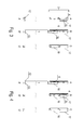
- Fig. 5a presents one half of a door suspension and guiding arrangement 3 according to another embodiment.
- the door panels 1a, 1b, 1c are aligned next to each other to close the doorway together with the corresponding door panels from the opposite side (not shown in the drawing).
- the door has six door panels in which all three door panels 1a, 1b, 1c opening to the left share one guide rail 8.
- the guide rail 8, as well as the corresponding guide rail on the other side of the door suspension and guiding arrangement (not shown), is mounted either to the door frame or to the elevator car.
- the vertical dashed line depicts the vertical center line of the doorway and the hatched area below the door panels 1a, 1b, 1c indicates the half of the door width when the door is open.
- Each door panel 1a, 1b or 1c moves along guide rail 8 with the assistance of guide rollers 6a and 7a, 6b and 7b or 6c and 7c, respectively.
- the wheelbase of the guide rollers 6a, 6b, 6c of each door panel 1a, 1b, 1c is approximately 2.5 times to 3 times as long as the width of the door panel 1a, 1b, 1c so, that the wheelbase is the longest for door panel 1c and shortest for door panel 1a.
- each panel guide 16a, 16b, 16c has two anti-tip rollers 10a and 11a, 10b and 11b or 10c and 11c, respectively, to stabilize the door panel 1a, 1b, 1c movement.
- the anti-tip rollers are mounted to the panel guide 16a, 16b, 16c and roll along the underside of the guide rail 8. Depending on the structure of the guide rail 8, they could also roll along its upper rim to balance the door panel 1a, 1b, 1c.
- only one anti-tip roller per door panel may be used as an alternative.
- the door panels according to this embodiment may be implemented without any anti-tip rollers.
- the door panels 1a, 1b, 1c are staggered appropriately to allow the free movement of the door panels 1a, 1b, 1c and guide rollers 6a, 6b, 6c.
- guide rollers 6a, 6b, 6c, 7a, 7b, 7c (as well as the shafts of the optional anti-tip rollers 10a, 10b, 10c, 11a, 11b, 11c) could be of different lengths and/or the panel guides 16a, 16b, 16c could be curved or nested.
- the panel guides 16a, 16b, 16c do not necessarily need to be of different height, this alternative was chosen in the drawing for clarity. Any conventional actuator can be used to move the door panels 1a, 1b, 1c and is not included in the drawing.
- the door arrangement can contain additional safety or automation devices which are omitted from this drawing.
- the movement of the door panels 1a, 1b, 1c during opening and closing of the door can be synchronized through any conventional method.
- the bottom part of the door frame or elevator car is drawn to contain a guiding groove 12.
- One or more guide shoes, sliding guides or roller shoes 13 is attached to each door panel or to at least one door panel and is allowed to move within the guiding groove 12 as described for Figs 1 , 3 and 4 .
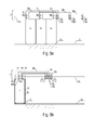
- Fig. 5b presents the door suspension and guiding arrangement of Fig. 5a when the door is open.
- the door panels 1a, 1b, 1c have moved to the left away from the doorway behind one another so, that door panel 1c is the foremost one in this view.
- the extended arms of the panel guides 16a, 16b, 16c to which the guide rollers 7a, 7b, 7c and the optional anti-tip rollers 11a, 11b, 11c are attached are scaled so, that in this position they are tightly aligned to allow the maximum wheelbase for the guide rollers 6a, 6b, 6c and 7a, 7b, 7c.
- shorter constructions are also possible.
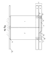
- Fig. 6a presents an example of another door suspension and guiding arrangement 3 in which there are two door panels 1, 2 and the door is closed (i.e. both door panels 1, 2 are closed).
- the vertical dashed line depicts the vertical center line of the doorway and the hatched area below the door panels 1, 2 indicates the door width when the door is open.
- the guide rails 8, 9 are mounted either to the door frame or to the elevator car.
- the panel guides are of different shape so that panel guide 16 has an elongated opening 14 through which the shaft 15 of guide roller 4 extends to guide rail 8.
- the opening 14 allows the panel guides to move in opposite directions along the same guide rail 8.
- the wheelbase of the guide rollers of each door panel is approximately two times as long as the width of the door panel. Because all the guide rollers 4, 5, 6, 7 are attached to the door panels 1, 2, through panel guides 16, 17, the wheelbase of guide rollers 4 and 5, 6 and 7, respectively, remains the same when the door panels are in the open position and in the closed position. Any conventional actuator can be used to move the door panels 1, 2 and is not included in the drawing.
- the door arrangement can contain additional safety or automation devices which are omitted from this drawing.
- the bottom part of the door frame or elevator car is drawn to contain a guiding groove 12.
- One or more guide shoes, sliding guides or roller shoes 13 is attached to each door panel or to at least one door panel and is allowed to move within the guiding groove 12 as described for Figs 1 , 3 and 4 .
- the parts which are behind another part in this view are indicated by dashed outline.
- Fig. 6b presents the door suspension and guiding arrangement of Fig. 6a when the door is open.
- the vertical dashed line depicts the vertical center line of the doorway and the hatched area indicates the door width.
- Door panel 1 has moved to the left side with the assistance of guide rollers 6 and 7, whereas door panel 2 has moved to the right side with the assistance of guide rollers 4 and 5. Because all the guide rollers 4, 5, 6, 7 are attached to the door panels 1, 2, through panel guides 16, 17, the wheelbase of guide rollers 4 and 5, 6 and 7, respectively, remains the same when the door panels are in the open position and in the closed position.
- Fig. 7 presents an elevator 18 comprising an elevator shaft 19, an elevator car 20 arranged to move within the elevator shaft 19, an elevator car door 21 and two or more landing doors 22.
- the elevator 18 is shown as a longitudinal transverse view depicting two floor levels 23a, 23b and their respective landing doors 22, but there could be more of them. All support, controlling and safety devices for the elevator 18 are omitted from the picture for clarity, and any conventional methods can be used for their design.
- the door suspension and guiding arrangement used in the elevator of Fig. 7 one door panel 1, 2 for each door 21, 22 is shown. Only an overview of the panel suspension and guiding arrangement 3 is shown without details of its components, which are more closely described in previous figures.
- the panel suspension and guiding arrangement 3 in this embodiment can be implemented according to any of the previous embodiments disclosed herein. Accordingly those embodiments are not repeated here but reference are made to them for the implementation of the panel suspension and guiding arrangement 3.
- a guiding groove 12 and a guiding shoe, sliding guide or roller shoe 13 is shown in the lower part of each door panel 1, 2, a guiding groove 12 and a guiding shoe, sliding guide or roller shoe 13 is shown.
- the elevator car is in the lower floor level 23a of the two and the elevator car door 21 and the landing door 22 are aligned.
- the opening and closing of both doors is synchronized through specialized devices which are not shown and many alternatives for which are known in the art.
- the elevator car door 21 and the landing door 22 are arranged in the same way as now for the lower floor level 23a.
Landscapes
- Elevator Door Apparatuses (AREA)
Abstract
A suspension and guiding arrangement for centrally opening panel doors for elevators that comprises two or more door panels (1, 2) supported by a panel suspension and guiding arrangement (3) so, that each door panel (1, 2) has a panel guide to which guide rollers (4, 5, 6, 7) are attached. Said guide rollers allow the respective door panel (1 or 2) to move in the direction of a guide rail (8, 9) between a closed and an open position of the door and the wheelbase of the guide rollers (4, 5, 6, 7) is longer than the width of the door panel (1, 2).
Description
- The present invention relates to a suspension and guiding arrangement for centrally opening panel doors for elevators.
- Most modern elevators have door systems based on horizontally moving door panels, which can open either centrally or from one side. The number of moving door panels typically varies from one in small passenger elevators to six in wide freight elevators. For the elevator to function smoothly, its doors have to be safe, function reliably and be easy to maintain. The comfort of the travel requires that the doors should be silent and move steadily during operation. The preferred door configuration in modern elevators is central opening, because this arrangement exhibits the shortest opening and closing times, as well as the best traffic performance. Elevators typically have a door both in the shaft doorway, which is called a landing door, to prevent falling into the shaft, as well as in the elevator car doorway to protect the passengers during elevator movement. The general structure of both doors is similar, i.e. they usually have the same opening configuration and the number of door panels. However, they can have differences for example in their locking mechanisms, fire-resistance and soundproofing properties.
- The door panels typically hang from a suspension and guiding arrangement comprising at least one guide rail attached to the door frame and, for each door panel, a panel guide and two or more wheels called guide rollers. The panel guide can vary in shape and be either continuous piece with the door panel, or be constructed from one or more separate pieces attached to the door panel. The guide rollers are attached either to the panel guide or to the guide rail and allow the movement of the door panel along the guide rail by rotating (as disclosed for example in the patent
CH 365844 - In the patent document
US 4564087 , another solution is presented. According to this patent, there is a single continuous guiding rail at the top of the door frame and beneath the guide rail, on both sides of the door, there is a guide roller mounted to the door frame. Additionally, the upper part of each panel has a cross member that contains a guide rail. Each cross member has an extension in the form of an arm, at the end of which there is a rotating roller which seats on the guide rail mounted to the door frame. The guide rail of the cross member moves on the stationary roller carried by the door frame during opening and closing of the door, whereas the rotating roller at the end of each cross member arm moves along the guide rail mounted to the door frame. In this solution, as the door opens, the wheelbase of the rollers progressively shortens as the extreme open position of the door is approached. This increases the swaying towards the end of the opening movement and, especially in its open position, the door weight exerts a significant lever force on the guide rollers. Furthermore, the patent explicitly concerns only doors consisting of two panels, either of the center-opening or side-opening type. Additionally, the solution according toUS 4564087 is rather complicated as it requires a guide rail construction in the moving door panel. - An object of the present invention is to improve the door guiding properties of a door suspension and guiding arrangement for centrally opening automatic elevator doors. Another object is to improve the reliability and smoothness of the door function for centrally opening automatic elevator doors.
- By centrally opening doors herein is meant doors that slide horizontally sideways, where the moving can be arranged in different ways, such as rollers, wheels or guide shoes moving on guide rails or guide rails moving on rollers, wheels or guide shoes. The centrally opening doors can also move using other mechanisms than the above-mentioned ones.
- The door suspension and guiding arrangement for centrally opening elevator doors presented here is characterized by comprising two or more door panels supported by a panel suspension and guiding arrangement so, that each door panel has a panel guide comprising at least two guide rollers which rollers allow the respective door panel to move in the direction of a guide rail between a closed and an open position of the door and in that the distance between the two guide rollers is greater than the width of the door panel to which they are attached, the at least two guide rollers are configured to move with the movement of the door panel and the distance between the at least two guide rollers is substantially the same in all positions of the door panel.
- In another aspect there is disclosed an elevator comprising an elevator shaft, an elevator car arranged to move within the elevator shaft, an elevator car door and two or more landing doors, characterized in that a door suspension and guiding arrangement according is used in at least one of said doors.
- The door suspension and guiding arrangement offers at least one the following advantages over prior art:
- Increase in the wheelbase of the guide rollers, improving the guiding of the door panel. This reduces the door swaying caused by the play in the steering mechanism.
- Improvement of the lever ratio of the wheels due to increased wheelbase, which reduces the load on the guide rollers during door opening and thus improves the functional reliability of the door.
- Reduced swaying of the door reduces the need for anti-tip rollers which can be completely left out in appropriate situations.
- The door suspension and guiding arrangement can be utilized in both landing doors and elevator car doors, as the need for improved guiding exists in both.
- In one embodiment, the panel guide is attached to the door panel or is an integral part of the door panel.
- In another embodiment, the door panel is supported by guide rollers.
- In another embodiment, the distance between the two guide rollers is exactly the same in all positions of the door panel.
- In another embodiment, there are more than two guide rollers attached to at least one door panel.
- In another embodiment, the guide rollers are configured to move within or on top of the guide rail.
- In another embodiment, each door panel has two guide rollers located substantially at opposite ends of the panel guide.
- In another embodiment, at least one anti-tip roller is included in the panel guide.
- In another embodiment, each panel guide has its own guide rail.
- In another embodiment, at least some of the door panels opening to the left use a common guide rail and at least some of the door panels opening to the right use a another common guide rail.
- In yet another embodiment, each door panel is supported by two guide rails so, that all the guide rollers closest to the vertical center line of doorway when the door is open use a common guide rail and the other guide rollers use a second common guide rail.
- In yet another embodiment, the door suspension and guiding arrangement is used in a landing door.
- In yet another embodiment, the door suspension and guiding arrangement is used in an elevator car door.
- The accompanying drawings, which are included to provide a further understanding of the invention and constitute a part of this specification, illustrate embodiments of the invention and together with the description help to explain the principles of the invention but the invention is not limited to the specific embodiments illustrated in the drawings. In the drawings:
-
Fig. 1 presents a schematic overview of one embodiment with two door panels when the door is closed. -
Fig. 2 presents a schematic overview of the embodiment ofFig. 1 when the door is open. -
Fig. 3 presents a transverse view of the door suspension and guiding arrangement ofFig. 1 along the lines A-A', B-B' and C-C'. -
Fig. 4 presents a transverse view of the door suspension and guiding arrangement ofFig. 2 along the lines A-A', B-B' and C-C'. -
Fig. 5a presents a schematic overview of another embodiment in which at least some of the door panels opening to the left use a common guide rail and at least some of the door panels opening to the right use a another common guide rail. InFig 5a , the door is closed and only the door panels opening to the left are shown. -
Fig. 5b presents a schematic overview of the embodiment ofFig. 5a when the door is open. Only the door panels moving to the left are shown. -
Fig. 6a presents a schematic overview of another embodiment in which the guide rollers closest to the vertical center line of the doorway when the door is open, use a common guide rail and the other guide rollers use a second common guide rail. InFig 6a , the door is closed. -
Fig. 6b presents a schematic overview of the embodiment ofFig 6a when the doors are open. -
Fig 7 presents a schematic overview of an elevator in which a door suspension and guiding arrangement according to the present disclosure is used. -
Fig. 1 presents a door suspension and guidingarrangement 3 of an elevator door in which the door comprises twodoor panels own guide rail Fig. 1 , theguide rails guide rollers panel guide guide roller panel guide door panel guide rail guide rollers Fig. 1 presents only a generalized overview of its structure. In addition to the arm-shaped extension of the panel guide presented inFig. 1 (i.e. thepanel guide panel guide Fig. 1 , eachpanel guide respective door panel door panel panel guide respective door panel Door panel 1 opens to the left alongguide rail 9 with the assistance ofguide rollers Door panel 2 opens to the right alongguide rail 8 with the assistance ofguide rollers Fig. 1 , theguide rails guide rollers guide rails guide rollers Fig. 1 , this would cover almost the whole width of the doorway (indicated by the grey bar at the top ofFig. 1 ). This alternative would reduce the weight of the door suspension and guiding arrangement and further stabilize the construction. In this view,door panel 1 is partly behind door panel 2 (indicated by the dashed outline). Any conventional actuator can be used to move thedoor panels groove 12. At the bottom of the door panel one or more guide shoes, sliding guides orroller shoes 13 is attached to each door panel or to at least one door panel and is allowed to move within the guiding groove. This improves the stability of the door. Any conventional method can be used for their design and they are only included in the drawing for completeness of the door structure. The hatched area inFig. 1 drawn below the door panels indicates the width of the door when it is open and is not part of the construction but included in the drawing for clarity. -
Fig. 2 presents the door suspension and guiding arrangement ofFig. 1 when the door is open. Thedoor panel 1 has moved to the left alongguide rail 9 with the assistance ofguide rollers door panel 2 has moved to the right alongguide rail 8 with the assistance ofguide rollers guide rollers guide rollers Fig. 1 ). -
Figures 3 and 4 present the door suspension and guidingarrangement 3 ofFigures 1 and2 along three longitudinal transverse lines, A-A', B-B' and C-C' (the dashed lines indicated inFigs. 1 and2 ). InFig. 3 , the door is closed and inFig. 4 the door is open. Only the top and bottom parts of the door arrangement are shown. In this example, theguide rails door panel guide rails different guide rails guide roller adjacent guide rails shaft 15 connectingguide roller 4 todoor panel 2 is longer than that connectingguide roller 6 todoor panel 1. Guide roller 5 (although not illustrated inFig. 3 ) can be arranged in the same manner asguide roller 4. Guide roller 7 (although not illustrated inFig. 3 ) can be arranged in the same manner asguide roller 6. The guidinggroove 12 and guide shoes, sliding guides orroller shoes 13 described inFig. 1 are also shown. Although the guide shoe, sliding guide orroller shoe 13 is drawn here as a cross section of a guide shoe, it can have any alternative construction, such as a wheel, or a ball or a slider, known in the field for such a structure. It can take support either from the side walls or from the bottom of the guidinggroove 12 and it can be an integral part of thedoor panel -
Fig. 5a presents one half of a door suspension and guidingarrangement 3 according to another embodiment. In this example it is the left half and the door is closed. Thedoor panels door panels guide rail 8. Theguide rail 8, as well as the corresponding guide rail on the other side of the door suspension and guiding arrangement (not shown), is mounted either to the door frame or to the elevator car. The vertical dashed line depicts the vertical center line of the doorway and the hatched area below thedoor panels door panel guide rail 8 with the assistance ofguide rollers guide rollers door panel door panel door panel 1c and shortest fordoor panel 1a. The exact length of the wheelbase, however, depends on the length and positioning of the panel guides 16a, 16b, 16c and can vary. Eachpanel guide anti-tip rollers door panel panel guide guide rail 8. Depending on the structure of theguide rail 8, they could also roll along its upper rim to balance thedoor panel door panels door panels guide rollers guide rollers optional anti-tip rollers door panels door panels groove 12. One or more guide shoes, sliding guides orroller shoes 13 is attached to each door panel or to at least one door panel and is allowed to move within the guidinggroove 12 as described forFigs 1 ,3 and 4 . The parts which are behind another part in this view are indicated by dashed outline.
Fig. 5b presents the door suspension and guiding arrangement ofFig. 5a when the door is open. Thedoor panels door panel 1c is the foremost one in this view. The extended arms of the panel guides 16a, 16b, 16c to which theguide rollers optional anti-tip rollers guide rollers -
Fig. 6a presents an example of another door suspension and guidingarrangement 3 in which there are twodoor panels door panels door panels guide rails guide rollers guide rail 8. Theguide rollers other guide rail 9. The panel guides are of different shape so that panel guide 16 has an elongatedopening 14 through which theshaft 15 ofguide roller 4 extends to guiderail 8. Theopening 14 allows the panel guides to move in opposite directions along thesame guide rail 8. In this example, the wheelbase of the guide rollers of each door panel is approximately two times as long as the width of the door panel. Because all theguide rollers door panels guide rollers door panels groove 12. One or more guide shoes, sliding guides orroller shoes 13 is attached to each door panel or to at least one door panel and is allowed to move within the guidinggroove 12 as described forFigs 1 ,3 and 4 . The parts which are behind another part in this view are indicated by dashed outline. -
Fig. 6b presents the door suspension and guiding arrangement ofFig. 6a when the door is open. The vertical dashed line depicts the vertical center line of the doorway and the hatched area indicates the door width.Door panel 1 has moved to the left side with the assistance ofguide rollers door panel 2 has moved to the right side with the assistance ofguide rollers guide rollers door panels guide rollers -
Fig. 7 presents anelevator 18 comprising anelevator shaft 19, anelevator car 20 arranged to move within theelevator shaft 19, anelevator car door 21 and two ormore landing doors 22. InFig. 7 , theelevator 18 is shown as a longitudinal transverse view depicting twofloor levels respective landing doors 22, but there could be more of them. All support, controlling and safety devices for theelevator 18 are omitted from the picture for clarity, and any conventional methods can be used for their design. In the door suspension and guiding arrangement used in the elevator ofFig. 7 , onedoor panel door arrangement 3 is shown without details of its components, which are more closely described in previous figures. The panel suspension and guidingarrangement 3 in this embodiment can be implemented according to any of the previous embodiments disclosed herein. Accordingly those embodiments are not repeated here but reference are made to them for the implementation of the panel suspension and guidingarrangement 3. In the lower part of eachdoor panel groove 12 and a guiding shoe, sliding guide orroller shoe 13 is shown. The elevator car is in thelower floor level 23a of the two and theelevator car door 21 and the landingdoor 22 are aligned. The opening and closing of both doors is synchronized through specialized devices which are not shown and many alternatives for which are known in the art. In thehigher floor level 23b only the landingdoor 22 is present and when theelevator car 20 moves to this level along theelevator shaft 19, theelevator car door 21 and the landingdoor 22 are arranged in the same way as now for thelower floor level 23a. - The above embodiments are to be understood as illustrative examples of the invention. Further embodiments of the invention are envisaged. It is to be understood that any feature described in relation to any one embodiment may be used alone, or in combination with other features described, and may also be used in combination with one or more features of any other of the embodiments, or any combination of any other of the embodiments. Furthermore, equivalents and modifications not described above may also be employed without departing from the scope of the invention, which is defined in the accompanying claims.
Claims (15)
- A door suspension and guiding arrangement for centrally opening elevator doors comprising two or more door panels (1, 2) supported by a panel suspension and guiding arrangement (3) so, that each door panel (1, 2) has a panel guide (16, 17) comprising at least two guide rollers (4, 5, 6, 7), which rollers allow the respective door panel (1 or 2) to move in the direction of a guide rail (8, 9) between a closed and an open position of the door, characterized in that the distance between the two guide rollers (4, 5; 6, 7) is greater than the width of the door panel (1, 2) to which they are attached, the at least two guide rollers (4, 5; 6, 7) are configured to move with the movement of the door panel (1, 2) and the distance between the at least two guide rollers (4, 5; 6, 7) is substantially the same in all positions of the door panel (1, 2).
- A door suspension and guiding arrangement according to claim 1, characterized in that the panel guide (16, 17) is attached to the door panel (1, 2) or is an integral part of the door panel (1, 2).
- A door suspension and guiding arrangement according to claim 1 or 2, characterized in that the panel suspension and guiding arrangement (3) is above the door panel (1, 2) when the door arrangement is installed.
- A door suspension and guiding arrangement according to any of the preceding claims, characterized in that the door panel (1, 2) is supported by the guide rollers (4, 5, 6, 7).
- A door suspension and guiding arrangement according to any of the preceding claims, characterized in that the distance between the two guide rollers is exactly the same in all positions of the door panel.
- A door suspension and guiding arrangement according to any of the preceding claims, characterized in that each door panel has two guide rollers (4, 5, 6, 7) located substantially at opposite ends of the panel guide (16, 17).
- A door suspension and guiding arrangement according to any of the preceding claims, characterized in that there are more than two guide rollers (4, 5, 6, 7) attached to at least one door panel (1, 2).
- A door suspension and guiding arrangement according to any of the preceding claims, characterized in that the guide rollers (4, 5, 6, 7) are configured to move within or on top of the guide rail (8, 9).
- A door suspension and guiding arrangement according to any of the preceding claims, characterized in that at least one anti-tip roller (10, 11) is included in the panel guide (16, 17).
- A door suspension and guiding arrangement according to any of the preceding claims, characterized in that each door panel (1, 2) has its own guide rail (8, 9)
- A door suspension and guiding arrangement according to any of the preceding claims, characterized in that at least some of the door panels (1 or 2) opening to the left side use a common guide rail (8 or 9) and at least some of the door panels (1 or 2) opening to the right side use another common guide rail (8 or 9).
- A door suspension and guiding arrangement according to any of the preceding claims, characterized in that each door panel (1, 2) is supported by two guide rails so, that the guide rollers (4, 7) closest to the vertical center line of the doorway when the door is open, use a common guide rail (8) and the other guide rollers (5, 6) use a second common guide rail (9).
- A door suspension and guiding arrangement according to any of the preceding claims, characterized in that it is used in a landing door.
- A door suspension and guiding arrangement according to any of the claims 1-12, characterized in that it is used in an elevator car door.
- An elevator (18) comprising an elevator shaft (19), an elevator car (20) arranged to move within the elevator shaft (19), an elevator car door (21) and two or more landing doors (22), characterized in that a door suspension and guiding arrangement (3) according any of the preceding claims is used in at least one of said doors.
Priority Applications (1)
| Application Number | Priority Date | Filing Date | Title |
|---|---|---|---|
| EP13161956.1A EP2786951A1 (en) | 2013-04-02 | 2013-04-02 | Door suspension and guiding arrangement for centrally opening panel doors, especially in elevators |
Applications Claiming Priority (1)
| Application Number | Priority Date | Filing Date | Title |
|---|---|---|---|
| EP13161956.1A EP2786951A1 (en) | 2013-04-02 | 2013-04-02 | Door suspension and guiding arrangement for centrally opening panel doors, especially in elevators |
Publications (1)
| Publication Number | Publication Date |
|---|---|
| EP2786951A1 true EP2786951A1 (en) | 2014-10-08 |
Family
ID=48082895
Family Applications (1)
| Application Number | Title | Priority Date | Filing Date |
|---|---|---|---|
| EP13161956.1A Withdrawn EP2786951A1 (en) | 2013-04-02 | 2013-04-02 | Door suspension and guiding arrangement for centrally opening panel doors, especially in elevators |
Country Status (1)
| Country | Link |
|---|---|
| EP (1) | EP2786951A1 (en) |
Citations (4)
| Publication number | Priority date | Publication date | Assignee | Title |
|---|---|---|---|---|
| CH365844A (en) | 1958-12-13 | 1962-11-30 | Schweiz Wagons Aufzuegefab | Door drive device for elevators |
| US4564087A (en) | 1982-04-02 | 1986-01-14 | Inventio Ag | Double panel sliding door, especially for elevators |
| WO2001062653A2 (en) * | 2000-02-25 | 2001-08-30 | Otis Elevator Company | Telescopic elevator door |
| JP2010120703A (en) * | 2008-11-17 | 2010-06-03 | Sanyo Kiko Kk | Elevator device |
-
2013
- 2013-04-02 EP EP13161956.1A patent/EP2786951A1/en not_active Withdrawn
Patent Citations (4)
| Publication number | Priority date | Publication date | Assignee | Title |
|---|---|---|---|---|
| CH365844A (en) | 1958-12-13 | 1962-11-30 | Schweiz Wagons Aufzuegefab | Door drive device for elevators |
| US4564087A (en) | 1982-04-02 | 1986-01-14 | Inventio Ag | Double panel sliding door, especially for elevators |
| WO2001062653A2 (en) * | 2000-02-25 | 2001-08-30 | Otis Elevator Company | Telescopic elevator door |
| JP2010120703A (en) * | 2008-11-17 | 2010-06-03 | Sanyo Kiko Kk | Elevator device |
Similar Documents
| Publication | Publication Date | Title |
|---|---|---|
| US20030033754A1 (en) | Elevator door sill assembly | |
| EP2748094B1 (en) | Elevator roller guide | |
| JP6013559B1 (en) | Elevator door equipment | |
| JP4644721B2 (en) | Elevator doorway device | |
| US9561937B2 (en) | Counterweight arrangement for an elevator and an elevator | |
| US8684143B2 (en) | Elevator guide rail system | |
| JP5572530B2 (en) | Elevator equipment | |
| KR20160001040U (en) | Frame for platform door apparatus of elevator | |
| JP5932081B1 (en) | Elevator running clearance occlusion device | |
| US8272481B2 (en) | Guide assembly for at least one elevator door | |
| EP2485976B1 (en) | System for moving on single rail the telescopic doors of an elevator cabin and the floor doors | |
| JP5842638B2 (en) | Emergency elevator sill equipment | |
| JP2015093767A (en) | Elevator door-open travel prevention device and method for installing door-open travel prevention device | |
| CN101616860B (en) | Mechanism for operating lift doors | |
| JP7231072B1 (en) | elevator door sill | |
| KR101617209B1 (en) | elevator door breakaway prevention apparatus | |
| JP6184264B2 (en) | Movable home fence | |
| JP2010208737A (en) | Sill for elevator landing door | |
| JP2013060286A (en) | Gateway device of elevator | |
| JP2012106835A (en) | Elevator door guide device | |
| BG3648U1 (en) | Mechanism for automatic telescopic elevator door | |
| JP6293006B2 (en) | Elevator door sill, door device using the same, and elevator device | |
| WO2013167929A1 (en) | Elevator car assembly | |
| BR202024003319U2 (en) | ELEVATOR CABIN | |
| RU2378180C2 (en) | Elevator |
Legal Events
| Date | Code | Title | Description |
|---|---|---|---|
| PUAI | Public reference made under article 153(3) epc to a published international application that has entered the european phase |
Free format text: ORIGINAL CODE: 0009012 |
|
| 17P | Request for examination filed |
Effective date: 20130402 |
|
| AK | Designated contracting states |
Kind code of ref document: A1 Designated state(s): AL AT BE BG CH CY CZ DE DK EE ES FI FR GB GR HR HU IE IS IT LI LT LU LV MC MK MT NL NO PL PT RO RS SE SI SK SM TR |
|
| AX | Request for extension of the european patent |
Extension state: BA ME |
|
| STAA | Information on the status of an ep patent application or granted ep patent |
Free format text: STATUS: THE APPLICATION IS DEEMED TO BE WITHDRAWN |
|
| 18D | Application deemed to be withdrawn |
Effective date: 20150409 |