EP2786851A1 - Method for manufacturing a sound-absorbing element, in particular for a motor vehicle - Google Patents
Method for manufacturing a sound-absorbing element, in particular for a motor vehicle Download PDFInfo
- Publication number
- EP2786851A1 EP2786851A1 EP13305430.4A EP13305430A EP2786851A1 EP 2786851 A1 EP2786851 A1 EP 2786851A1 EP 13305430 A EP13305430 A EP 13305430A EP 2786851 A1 EP2786851 A1 EP 2786851A1
- Authority
- EP
- European Patent Office
- Prior art keywords
- mould
- heavy layer
- mould part
- foam
- recess
- Prior art date
- Legal status (The legal status is an assumption and is not a legal conclusion. Google has not performed a legal analysis and makes no representation as to the accuracy of the status listed.)
- Granted
Links
Images
Classifications
-
- B—PERFORMING OPERATIONS; TRANSPORTING
- B29—WORKING OF PLASTICS; WORKING OF SUBSTANCES IN A PLASTIC STATE IN GENERAL
- B29C—SHAPING OR JOINING OF PLASTICS; SHAPING OF MATERIAL IN A PLASTIC STATE, NOT OTHERWISE PROVIDED FOR; AFTER-TREATMENT OF THE SHAPED PRODUCTS, e.g. REPAIRING
- B29C44/00—Shaping by internal pressure generated in the material, e.g. swelling or foaming ; Producing porous or cellular expanded plastics articles
- B29C44/34—Auxiliary operations
- B29C44/58—Moulds
-
- B—PERFORMING OPERATIONS; TRANSPORTING
- B29—WORKING OF PLASTICS; WORKING OF SUBSTANCES IN A PLASTIC STATE IN GENERAL
- B29C—SHAPING OR JOINING OF PLASTICS; SHAPING OF MATERIAL IN A PLASTIC STATE, NOT OTHERWISE PROVIDED FOR; AFTER-TREATMENT OF THE SHAPED PRODUCTS, e.g. REPAIRING
- B29C44/00—Shaping by internal pressure generated in the material, e.g. swelling or foaming ; Producing porous or cellular expanded plastics articles
- B29C44/02—Shaping by internal pressure generated in the material, e.g. swelling or foaming ; Producing porous or cellular expanded plastics articles for articles of definite length, i.e. discrete articles
- B29C44/12—Incorporating or moulding on preformed parts, e.g. inserts or reinforcements
- B29C44/1214—Anchoring by foaming into a preformed part, e.g. by penetrating through holes
-
- B—PERFORMING OPERATIONS; TRANSPORTING
- B29—WORKING OF PLASTICS; WORKING OF SUBSTANCES IN A PLASTIC STATE IN GENERAL
- B29K—INDEXING SCHEME ASSOCIATED WITH SUBCLASSES B29B, B29C OR B29D, RELATING TO MOULDING MATERIALS OR TO MATERIALS FOR MOULDS, REINFORCEMENTS, FILLERS OR PREFORMED PARTS, e.g. INSERTS
- B29K2075/00—Use of PU, i.e. polyureas or polyurethanes or derivatives thereof, as moulding material
-
- B—PERFORMING OPERATIONS; TRANSPORTING
- B29—WORKING OF PLASTICS; WORKING OF SUBSTANCES IN A PLASTIC STATE IN GENERAL
- B29K—INDEXING SCHEME ASSOCIATED WITH SUBCLASSES B29B, B29C OR B29D, RELATING TO MOULDING MATERIALS OR TO MATERIALS FOR MOULDS, REINFORCEMENTS, FILLERS OR PREFORMED PARTS, e.g. INSERTS
- B29K2623/00—Use of polyalkenes or derivatives thereof for preformed parts, e.g. for inserts
-
- B—PERFORMING OPERATIONS; TRANSPORTING
- B29—WORKING OF PLASTICS; WORKING OF SUBSTANCES IN A PLASTIC STATE IN GENERAL
- B29K—INDEXING SCHEME ASSOCIATED WITH SUBCLASSES B29B, B29C OR B29D, RELATING TO MOULDING MATERIALS OR TO MATERIALS FOR MOULDS, REINFORCEMENTS, FILLERS OR PREFORMED PARTS, e.g. INSERTS
- B29K2995/00—Properties of moulding materials, reinforcements, fillers, preformed parts or moulds
- B29K2995/0001—Properties of moulding materials, reinforcements, fillers, preformed parts or moulds having particular acoustical properties
- B29K2995/0002—Properties of moulding materials, reinforcements, fillers, preformed parts or moulds having particular acoustical properties insulating
-
- B—PERFORMING OPERATIONS; TRANSPORTING
- B29—WORKING OF PLASTICS; WORKING OF SUBSTANCES IN A PLASTIC STATE IN GENERAL
- B29K—INDEXING SCHEME ASSOCIATED WITH SUBCLASSES B29B, B29C OR B29D, RELATING TO MOULDING MATERIALS OR TO MATERIALS FOR MOULDS, REINFORCEMENTS, FILLERS OR PREFORMED PARTS, e.g. INSERTS
- B29K2995/00—Properties of moulding materials, reinforcements, fillers, preformed parts or moulds
- B29K2995/0037—Other properties
- B29K2995/0063—Density
-
- B—PERFORMING OPERATIONS; TRANSPORTING
- B29—WORKING OF PLASTICS; WORKING OF SUBSTANCES IN A PLASTIC STATE IN GENERAL
- B29L—INDEXING SCHEME ASSOCIATED WITH SUBCLASS B29C, RELATING TO PARTICULAR ARTICLES
- B29L2009/00—Layered products
-
- B—PERFORMING OPERATIONS; TRANSPORTING
- B29—WORKING OF PLASTICS; WORKING OF SUBSTANCES IN A PLASTIC STATE IN GENERAL
- B29L—INDEXING SCHEME ASSOCIATED WITH SUBCLASS B29C, RELATING TO PARTICULAR ARTICLES
- B29L2031/00—Other particular articles
- B29L2031/30—Vehicles, e.g. ships or aircraft, or body parts thereof
- B29L2031/3005—Body finishings
Definitions
- the invention relates to a method for manufacturing a sound-absorbing element, in particular for a motor vehicle.
- a sound-absorbing element is intended to form a lining for a floor panel, for a dash inner or for any other inner part of a motor vehicle.
- a sound-absorbing element is well known from prior art. Such a sound-absorbing element, called of a "mass/spring” type, comprises a heavy layer and foam associated together.
- the heavy layer is generally made of a sheet having an area density between 1 and 8 kg/m 2 , and a density of about 2000 kg / m 3 .
- This heavy layer comprises a first face, and a second face opposite to the first face.
- the foam is assembled to the heavy layer on said second face.
- the sound-absorbing element comprises at least one through aperture, intended to allow passage of a component, such as a ventilation air duct.
- a component such as a ventilation air duct.
- Such a seal is intended to prevent sound or air leakage between said component and the outline of the through aperture.
- Such a method comprises a moulding operation, comprising a step of arranging a heavy layer in a mould device, and a step of injecting foam in the mould device so as to assemble the injected foam with the second face of the heavy layer.
- the method then comprises an operation of bringing and fastening a seal element onto the first face of the heavy layer, around the through aperture.
- the seal element is glued on the heavy layer.
- This operation is usually manually conducted. Thus, this operation can be long and expensive to conduct. Moreover, the position of a manually fastened seal may not be as accurate as desired.
- the invention aims to solve these problems, by proposing a method for manufacturing a sound-absorbing element comprising a seal element, without an additional operation of bringing and fastening this seal element onto the heavy layer.
- the invention relates to a method for manufacturing a sound-absorbing element, in particular for a motor vehicle, wherein the said sound-absorbing element comprises a heavy layer assembled with foam, and at least one through aperture, characterized in that the method comprises:
- This method allows the seal element to be realized during the same moulding operation as the foam. More particularly, the seal element is made of the same material as the foam.
- the position of the seal element is set by the recess, so that the method according to the invention allows the seal element to be correctly positioned.
- the method of the invention involves a better result than a method from prior art, and it is faster and less expensive.
- a method according to the invention may comprise any of the following features, taken alone or in any possible combination.
- the invention also relates to a mould device, for performing a method of manufacturing as previously disclosed, comprising:
- Such a mould device is adapted for performing the previously disclosed method.
- a mould device according to the invention can comprise any of the following features, taken alone or in any possible combination.
- the invention also related to a sound-absorbing element, manufactured during a method as previously disclosed, by means of a mould device as previously disclosed, comprising a heavy layer having a first face and a second face opposite to the first face, and foam fastened to the second face, wherein the sound-absorbing element has at least one through aperture, characterized in that :
- this sound-absorbing element 10 is intended to form a lining for a dash inner of a motor vehicle.
- a dash inner is intended to be arranged between a passenger compartment and a motor compartment of the vehicle, so that this sound-absorbing element 10 is intended to absorb at least a part of sounds that comes from the motor towards the passenger compartment.
- the sound-absorbing element 10 is of the "mass/spring” type, that is it comprises a heavy layer 12 and foam 14 associated together.
- the heavy layer 12 is made of a sheet having an area density between 1 and 8 kg/m 2 , and a density of about 2000 kg / m 3 .
- this heavy layer is made of a thermoplastic material based on polyolefin, on copolymer of ethylene and vinyl acetate, on an Ethylene Propylene Diene Monomer (EPDM) or on a mixture of these polymers. It also preferably includes fillers based on chalk or on barium sulphate.
- the heavy layer 12 comprises a first face 12A, intended to be turned towards the passenger compartment of the motor vehicle, and a second face 12B, opposite to the first face 12A, intended to be turned towards the motor compartment.
- the second face 12B is turned towards a noise source
- the first face 12A is turned towards an area intended to be sound-isolated relating to said noise source.
- the foam 14 is assembled on the second face 12B of the heavy layer 12.
- the foam is made of Polyurethane (PU).
- the sound-absorbing element 10 has at least a through aperture 16, for instance two through apertures 16, each intended to allow a component to pass through this sound-absorbing element 10.
- each through aperture in the sound-absorbing element 10 corresponds to a through aperture in the heavy layer 12 and to a through aperture in the foam 14.
- Each through aperture 16 in the heavy layer 12 is more precisely shown on figure 2 , seen from the side of the second face 12B, and on figure 3 , seen from the side of the first face 12A.
- sound-absorbing element 10 comprises a seal element 18 for each aperture 16.
- Said seal element 18 is made of a part of foam fastened to the first face 12A of the heavy layer 12, around the aperture 16.
- the seal element 18 is ring shaped.
- the heavy layer 12 has at least one through hole 20 near the through aperture 16, as shown on figure 3 .
- the foam 14 fastened to the second face 12B of the heavy layer 12 is connected to the seal element 18 fastened to the first face 12A, through this through hole 20.
- the seal element 18 is made of the same material as the foam 14. It should be noticed that this material (PU) is well adapted for a sealing function against sound or air leakages.
- the heavy layer 12 has a plurality of through holes 20, distributed around each through aperture 16, so that the seal element 18 is homogeneously arranged around the through aperture 16, as specified later.
- each hole 20 is separated from adjacent other holes 20 by a distance of about 5 cm.
- a mould device 22 for manufacturing the sound-absorbing element 10 will now be disclosed, with reference to figures 4 to 7 .
- the mould device 22 comprises a first mould part 22A, more detailed on figure 6 , and a second mould part 22B, more detailed on figure 7 , complementary with the first mould part 22A. When assembled together, these first 22A and second 22B mould parts delimits together a shut mould cavity 24.
- the first 22A and second 22B mould parts can be assembled together in two possible positions, said first and second positions.
- actuators are intended to apply a pressure on the second mould part 22B in order to apply it against the first mould part 22A.
- the distance between the first 22A and the second 22B mould parts is higher in the first position than in the second position.
- the actuators apply a lower pressure in the first position than in the second position.
- the first mould part 22A comprises a reception area 26 for receiving the heavy layer 12. More particularly, the fist face 12A of the heavy layer 12 is intended to be arranged against this reception area 26.
- the mould device 22 comprises means for pressing the heavy layer against the reception area 26.
- these pressing means comprise means for creating a vacuum between the heavy layer 12 and the first mould part 22A.
- These pressing means are intended to press the heavy layer 12 against the reception area 26 so that this heavy layer 12, previously heated as disclosed later, takes a form complementary to the form of the reception area 26. In other words, these pressing means allows thermoforming the heavy layer 12.
- the second mould part 22B is provided with at least one injection duct (not shown) leading to the mould cavity 24. Material intended to form the foam 14 is usually injected in the mould cavity 24 through this injection duct.
- the first mould part 22A comprises, in the reception area 26, at least one recess 28.
- This recess 28 is intended to be arranged in front of an aperture area of the heavy layer 12, when this heavy layer 12 is arranged on the reception area 26.
- aperture area an area of the heavy layer 12 corresponding to a through aperture 16. More particularly, this area is called “aperture area” when the aperture is not cut, and is called “through aperture 16" when this aperture is cut. Thus, in the following disclosure, the wording "aperture area” refers to a same area as the wording "through aperture 16".
- Dimensions of the recess 28 are wider than dimensions of said through aperture 16. More particularly, dimensions of the recess 28 correspond to dimensions of the seal element 18.
- the through aperture 16 is cut inside the mould device 22.
- the first 22A and second 22B mould parts respectively comprise a first 29A and a second 29B complementary cutting elements intended to cut each aperture area into a through aperture 16 when these first 22A and second 22B mould parts are sufficiently compressed each other, i.e. are assembled in the second position.
- the first cutting element 29A is arranged on the first mould part 22A.
- this first cutting element 29A has a shape of a cylinder with a base having a curving shape, of the same shape as an inner outline of the sealing element 18. So, since this first cutting element 29A is arranged in the corresponding recess 28, this recess 28 has a shape of a ring around the first cutting element 29A.
- this first cutting element 29A has also a function of supporting the aperture area of the heavy layer 12 when this heavy layer 12 is arranged on the reception area 26.
- This first cutting element 29A supports the heavy layer 12, preventing it to deform into the recess 28, during the thermoforming of the heavy layer 12 by the pressing means.
- the second cutting element 29B is arranged on the second mould part 22B, so as to be arranged in front of the first cutting element 29A when the first 22A and second 22B mould parts are assembled.
- this second cutting element 29B has a shape of a ring, of a complementary shape with the shape of the through aperture 16, and with lateral dimensions that are slightly lower to outer lateral dimensions of the first cutting element 29A.
- the second cutting element 29B comes in contact with the second face 12B of the heavy layer 12, and the first cutting element 29A is used as a support for the second cutting element 29B, so that the heavy layer 12 is pinched between these first 29A and second 29B cutting elements.
- this second cutting element 29B participates to maintain the heavy layer 12 against the first mould part 22A in this first position.
- this second cutting element 29B prevents foam from filling the aperture area on the second face 12B of the heavy layer 12 in the area where it is not needed.
- the second cutting element 29B is pushed through the heavy layer 12, until this second cutting element 29B be in contact with the first cutting element 29A.
- the edge of the second cutting element 29B complementary works with the surface of the first cutting element 29A so as to cut the heavy layer 12, realizing the through aperture 16.
- the second mould part 22B comprises at least one strut element 31, protruding towards the second face 12B of the heavy layer 12.
- Each strut element 31 is preferentially arranged around the outline of the recess 28, so that the heavy layer 12 is pinched between the strut elements and the first mould part 22A when the mould cavity 24 is shut. This allows an improved maintaining of said outline area to prevent it to deform, in particular during the realization of the holes 20 and during the foam injection.
- each of the strut elements are sufficiently low to avoid disrupting a flow of foam between these strut elements.
- the second mould part 22B comprises at least one punch element 30, arranged in front of the recess 28 when the second mould part 22B is assembled with the first mould part 22A.
- Said punch element 30 comprises a rod 32 that is longitudinally movable between a retracted position and a deployed position.
- the punch element 30 comprises displacement means 34 for moving the rod 32.
- these displacement means 34 comprise a pneumatic plunger cylinder.
- each rod 32 has a distal end 36 that is flat or slightly domed. More particularly, the distal end 36 is adapted for punching the heavy layer 12 to make a hole, not for piercing this heavy layer 12. In other words, each hole 20 is made by removing all the material corresponding to this hole 20. Thus, a scrap, corresponding to the material from the hole 20, remains in the recess 28 after punching this hole 20. As it will be disclosed later, this scrap is then imbedded in the foam forming the sealing element 18.
- each rod 32 has a diameter equal to 12 mm.
- each punch element 30 is laterally arranged near an outline of the corresponding recess 28, so that this outline supports the heavy layer 12 when punched. It should be noticed that the second cutting element 29B and the strut elements 31 also maintain the heavy layer 12 when punched.
- the punch elements 30 are arranged between the second cutting element 29B and the strut elements 31, the area of the heavy layer 12 that is intended to be punched by these punch elements 30 is efficiently maintained on the both sides, as shown on figure 4 . Because of this efficiently maintaining on the both sides, the rod 32 can get across the heavy layer 12 without deforming it.
- the mould device 22 comprises heating means for heating the heavy layer 12 and the foam 14 to optimal temperature during the moulding of this foam 14.
- the mould device 22 comprises first heating means for heating a first area of the first mould part 22A, corresponding to the recess 28, and second heating means for heating a second area of the first mould part 22A, corresponding to the rest of the reception area 26.
- first heating means for heating a first area of the first mould part 22A, corresponding to the recess 28, and second heating means for heating a second area of the first mould part 22A, corresponding to the rest of the reception area 26.
- the recess 28, wherein the seal element 18 is moulded needs to be heated more than the rest of the heavy layer 12.
- the first heating means are heated to 65°C
- the second heating means are heated to 55°C.
- the mould device 22 also comprises third heating means for heating the second mould part 22B, intended to heat the foam 14. Preferentially, the third heating means are heated to 65°C.
- This third heating means can be connected to the first heating means, or in a variant can be independent from this first heating means.
- each heating means comprise tubes conveying a heat transfer fluid, circulating in the corresponding mould part near the corresponding area.
- the method first comprises a step 100 of providing the first mould part 22A as previously disclosed.
- the method then comprises a step 110 of heating the heavy layer 12, so as to have this heavy layer 12 deformable.
- the heavy layer 12 is arranged in an oven, and heated at a sufficient temperature so as to make it deformable.
- the method then comprises a step 120 of arranging the first face 12A of the hot heavy layer 12 onto the reception area 26. It should be noticed that each aperture area of the heavy layer 12 is arranged in front of a corresponding recess 28 of the first mould part 22A, and rests on the corresponding first cutting element 29A.
- the method then comprises a step 130 of pressing the heavy layer 12 against the reception area 26, for instance by creating a vacuum between the heavy layer 12 and the first mould part 22A. Since the heavy layer 12 is deformable, because it has been heated during the step of heating 120, and because it is kept hot by the first and second heating means, this heavy layer 12 takes a form complementary to the form of the reception area 26. In other words, this step 130 is a step of thermoforming the heavy layer 12.
- the method then comprises a step 140 of providing the second mould part 22B, and assembling the second mould part 22B with the first mould part 22A so as to delimit the shut mould cavity 24 between them.
- the first 22A and second 22B mould parts are assembled in the first position.
- the second cutting element 29B comes in contact with the second face 12B of the heavy layer 12.
- the method then comprises a step 150 of making at least one through hole 20 in the heavy layer 12, near each aperture area, so that each through hole 20 leads to the corresponding recess 28.
- Each through hole 20 is made by displacing the corresponding punch element 30 from its retracted position toward its deployed position, so as to punch the heavy layer 12 and thus to remove material from this heavy layer 12 to form the hole 20. It should be noted that scrap from this removing material then fells into the recess 28.
- Each punch element 30 is then returned to its retracted position, into a corresponding housing in the second mould part 22B.
- the method then comprises a step 160 of injecting the foam through the injection duct of the second mould part 22B, towards the mould cavity 24, so that the foam 14 adheres to the second face 12B of the heavy layer 12.
- a part of the foam flows through the holes 20 so as to fill the recesses 28, and so that this part of foam filling each recess 28 adheres to the first face 22A of the heavy layer 12, forming the seal element 18. It should be reminded that the holes 20 are arranged so that the foam is homogeneously distributed in the recess 28.
- the foam can expend in the recess 28 without escaping from this recess 28.
- the foam 14, 18 is kept at a temperature that is optimal for its realization.
- the step 160 is realized by injecting several foaming agents into the mould cavity 24, said foaming agents reacting together to form the foam 14.
- foam is fastened to the previously heated heavy layer 12, while this foam is formed by foaming agents reacting.
- the foaming agents are Isocianathe and Polyol.
- the method then comprises a step 170 assembling the second mould part 22B with the first mould part 22A in the second position.
- the actuators are activated for high pressure.
- the first 29A and second 29B cutting elements cooperate together to cut the corresponding through aperture 16.
- the method then comprises a usual finalisation step 180, comprising in particular degassing the foam 14, opening the mould device 22, and removing the finalized sound-absorbing element 10 from the mould device 22.
- the scrap corresponding to each cut through aperture 16 is also removed from the mould device 22.
Landscapes
- Vehicle Interior And Exterior Ornaments, Soundproofing, And Insulation (AREA)
Abstract
Description
- The invention relates to a method for manufacturing a sound-absorbing element, in particular for a motor vehicle. As an example, such a sound-absorbing element is intended to form a lining for a floor panel, for a dash inner or for any other inner part of a motor vehicle.
- A sound-absorbing element is well known from prior art. Such a sound-absorbing element, called of a "mass/spring" type, comprises a heavy layer and foam associated together.
- The heavy layer is generally made of a sheet having an area density between 1 and 8 kg/m2, and a density of about 2000kg/m 3. This heavy layer comprises a first face, and a second face opposite to the first face.
- The foam is assembled to the heavy layer on said second face.
- In some cases, the sound-absorbing element comprises at least one through aperture, intended to allow passage of a component, such as a ventilation air duct. In such a case, it is usually necessary to provide a seal element around the through aperture, said seal being fastened on the first face of the heavy layer. Such a seal is intended to prevent sound or air leakage between said component and the outline of the through aperture.
- A method for manufacturing such a sound-absorbing element is well known from prior art.
- Such a method comprises a moulding operation, comprising a step of arranging a heavy layer in a mould device, and a step of injecting foam in the mould device so as to assemble the injected foam with the second face of the heavy layer.
- The method then comprises an operation of bringing and fastening a seal element onto the first face of the heavy layer, around the through aperture. Generally, the seal element is glued on the heavy layer. This operation is usually manually conducted. Thus, this operation can be long and expensive to conduct. Moreover, the position of a manually fastened seal may not be as accurate as desired.
- The invention aims to solve these problems, by proposing a method for manufacturing a sound-absorbing element comprising a seal element, without an additional operation of bringing and fastening this seal element onto the heavy layer.
- To this end, the invention relates to a method for manufacturing a sound-absorbing element, in particular for a motor vehicle, wherein the said sound-absorbing element comprises a heavy layer assembled with foam, and at least one through aperture, characterized in that the method comprises:
- a step of providing a first mould part, comprising a reception area for receiving the heavy layer, said reception area having at least one recess whose lateral dimensions are wider than lateral dimensions of said through aperture,
- a step of arranging a first face of the heavy layer onto said reception area, so that an area corresponding to the through aperture is arranged in front of the recess,
- a step of providing a second mould part, and assembling the second mould part with the first mould part so as to delimit a shut mould cavity between them, said second mould part being provided with at least one conduit leading to the mould cavity,
- a step of making at least one through hole in the heavy layer, near the area corresponding to the through aperture, so that each through hole leads to the recess,
- a step of injecting the foam through the conduit towards the mould cavity, so that the foam adheres to a second face of the heavy layer, while a part of the foam flows through the hole so as to fill the recess, and so that this part of foam filling the recess adheres to the first face of the heavy layer.
- This method allows the seal element to be realized during the same moulding operation as the foam. More particularly, the seal element is made of the same material as the foam.
- Besides, the position of the seal element is set by the recess, so that the method according to the invention allows the seal element to be correctly positioned. In other words, the method of the invention involves a better result than a method from prior art, and it is faster and less expensive.
- Optionally, a method according to the invention may comprise any of the following features, taken alone or in any possible combination.
- The method comprises, before the step of arranging the heavy layer onto said reception area, a step of heating the heavy layer, so as to have this heavy layer deformable.
- The method comprises, after the step of arranging the heavy layer onto the reception area, a step of pressing this heavy layer against this reception area, for instance by creating a vacuum between the heavy layer and the first mould part.
- The invention also relates to a mould device, for performing a method of manufacturing as previously disclosed, comprising:
- a first mould part, comprising a reception area for receiving the heavy layer,
- a second mould part, complementary with the first mould part, so as to delimit a shut mould cavity with this first mould part when assembled together, said second mould part being provided with at least one conduit leading to the mould cavity,
characterized in that:- the first mould part comprises, in the reception area, at least one recess whose lateral dimensions are wider than lateral dimensions of the through aperture,
- the second mould part comprises at least one punch element, arranged in front of the recess when the second mould part is assembled with the first mould part, said punch element comprising a rod longitudinally movable between a retracted position and a deployed position.
- Such a mould device is adapted for performing the previously disclosed method.
- Optionally, a mould device according to the invention can comprise any of the following features, taken alone or in any possible combination.
- The mould device comprises means for pressing the heavy layer against the reception area, for instance means for creating a vacuum between the heavy layer and the first mould part.
- The mould device comprises: first heating means for heating a first area of the first mould part, corresponding to the recess, and second heating means for heating a second area of the first mould part, corresponding to the rest of the reception area.
- The first mould part comprises a first cutting element arranged in the recess, and the second mould part comprises a second cutting element, complementary to the first cutting element, arranged in front of this first cutting element when the first and second mould part are assembled together.
- The first and second mould part can be assembled in first and second position, so that: when an heavy layer is arranged on the reception area, the second cutting element is in contact with this heavy layer when the first and second mould part are assembled in the first position, and the second cutting element is engaged with the first cutting element when the first and second mould part are assembled in second first position.
- The second mould part comprises at least one strut element, protruding towards first mould part, each strut element being preferentially arranged around the recess.
- The invention also related to a sound-absorbing element, manufactured during a method as previously disclosed, by means of a mould device as previously disclosed, comprising a heavy layer having a first face and a second face opposite to the first face, and foam fastened to the second face, wherein the sound-absorbing element has at least one through aperture, characterized in that:
- the heavy layer has at least one through hole near the through aperture,
- a part of foam is fastened to the first face,
- the foam fastened to the second face is connected to the part of foam fastened to the first face through the through hole.
- Other aspects and advantages of the invention will become apparent on reading the following description, which is given by way of example and refers to the attached drawings in which:
-
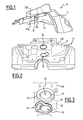
Figure 1 is a partial view in perspective of a sound-absorbing element according to an example of embodiment of the invention; -
Figure 2 is a view from rear of the sound-absorbing element offigure 1 , showing a foam side of this sound-absorbing element; -
Figure 3 is a partial view from front of the sound-absorbing element offigure 1 , showing a heavy layer side of this sound-absorbing element; -
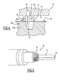
Figure 4 is a partial section of mould device for manufacturing the sound-absorbing element offigure 1 , according to an example of embodiment of the invention; -
Figure 5 is a view in perspective of a punch element equipping the mould part offigure 4 ; -
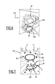
Figure 6 is a partial view in perspective from front of a lower part of the mould device offigure 4 ; -
Figure 7 is a partial view in perspective from front of a top part of the mould device offigure 4 ; -
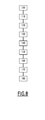
Figure 8 is a schematic representation of steps of a method of manufacturing the sound-absorbing element offigure 1 by means of the mould device offigure 4 . - With reference to
Figures 1 to 3 , we describe a sound-absorbingelement 10, in particular for a motor vehicle. For instance, this sound-absorbingelement 10 is intended to form a lining for a dash inner of a motor vehicle. Such a dash inner is intended to be arranged between a passenger compartment and a motor compartment of the vehicle, so that this sound-absorbingelement 10 is intended to absorb at least a part of sounds that comes from the motor towards the passenger compartment. - The sound-absorbing
element 10 is of the "mass/spring" type, that is it comprises aheavy layer 12 andfoam 14 associated together. - In a standard manner, the
heavy layer 12 is made of a sheet having an area density between 1 and 8 kg/m2, and a density of about 2000kg/m 3. For instance, this heavy layer is made of a thermoplastic material based on polyolefin, on copolymer of ethylene and vinyl acetate, on an Ethylene Propylene Diene Monomer (EPDM) or on a mixture of these polymers. It also preferably includes fillers based on chalk or on barium sulphate. - The
heavy layer 12 comprises afirst face 12A, intended to be turned towards the passenger compartment of the motor vehicle, and asecond face 12B, opposite to thefirst face 12A, intended to be turned towards the motor compartment. - More particularly, the
second face 12B is turned towards a noise source, and thefirst face 12A is turned towards an area intended to be sound-isolated relating to said noise source. - In a standard manner, the
foam 14 is assembled on thesecond face 12B of theheavy layer 12. Preferably, the foam is made of Polyurethane (PU). - The sound-absorbing
element 10 has at least a throughaperture 16, for instance two throughapertures 16, each intended to allow a component to pass through this sound-absorbingelement 10. - Naturally, each through aperture in the sound-absorbing
element 10 corresponds to a through aperture in theheavy layer 12 and to a through aperture in thefoam 14. Each throughaperture 16 in theheavy layer 12 is more precisely shown onfigure 2 , seen from the side of thesecond face 12B, and onfigure 3 , seen from the side of thefirst face 12A. - In order to prevent sound or air leakage between said component and the outline of the
aperture 16, sound-absorbingelement 10 comprises aseal element 18 for eachaperture 16. - Said
seal element 18 is made of a part of foam fastened to thefirst face 12A of theheavy layer 12, around theaperture 16. Thus, theseal element 18 is ring shaped. - According to the invention, the
heavy layer 12 has at least one throughhole 20 near the throughaperture 16, as shown onfigure 3 . Thefoam 14 fastened to thesecond face 12B of theheavy layer 12 is connected to theseal element 18 fastened to thefirst face 12A, through this throughhole 20. Thus, theseal element 18 is made of the same material as thefoam 14. It should be noticed that this material (PU) is well adapted for a sealing function against sound or air leakages. - Preferably, the
heavy layer 12 has a plurality of throughholes 20, distributed around each throughaperture 16, so that theseal element 18 is homogeneously arranged around the throughaperture 16, as specified later. For instance, eachhole 20 is separated from adjacentother holes 20 by a distance of about 5 cm. - A
mould device 22 for manufacturing the sound-absorbingelement 10 will now be disclosed, with reference tofigures 4 to 7 . - The
mould device 22 comprises afirst mould part 22A, more detailed onfigure 6 , and asecond mould part 22B, more detailed onfigure 7 , complementary with thefirst mould part 22A. When assembled together, these first 22A and second 22B mould parts delimits together ashut mould cavity 24. - According to the invention, the first 22A and second 22B mould parts can be assembled together in two possible positions, said first and second positions. To this end, actuators are intended to apply a pressure on the
second mould part 22B in order to apply it against thefirst mould part 22A. - More particularly, the distance between the first 22A and the second 22B mould parts is higher in the first position than in the second position. In other words, the actuators apply a lower pressure in the first position than in the second position.
- These first and second positions will be more detailed later.
- The
first mould part 22A comprises areception area 26 for receiving theheavy layer 12. More particularly, thefist face 12A of theheavy layer 12 is intended to be arranged against thisreception area 26. - Preferably, the
mould device 22 comprises means for pressing the heavy layer against thereception area 26. For instance, these pressing means comprise means for creating a vacuum between theheavy layer 12 and thefirst mould part 22A. - These pressing means are intended to press the
heavy layer 12 against thereception area 26 so that thisheavy layer 12, previously heated as disclosed later, takes a form complementary to the form of thereception area 26. In other words, these pressing means allows thermoforming theheavy layer 12. - In a usual manner, the
second mould part 22B is provided with at least one injection duct (not shown) leading to themould cavity 24. Material intended to form thefoam 14 is usually injected in themould cavity 24 through this injection duct. - According to the invention, the
first mould part 22A comprises, in thereception area 26, at least onerecess 28. Thisrecess 28 is intended to be arranged in front of an aperture area of theheavy layer 12, when thisheavy layer 12 is arranged on thereception area 26. - In the current disclosure, we call "aperture area" an area of the
heavy layer 12 corresponding to a throughaperture 16. More particularly, this area is called "aperture area" when the aperture is not cut, and is called "throughaperture 16" when this aperture is cut. Thus, in the following disclosure, the wording "aperture area" refers to a same area as the wording "throughaperture 16". - Dimensions of the
recess 28 are wider than dimensions of said throughaperture 16. More particularly, dimensions of therecess 28 correspond to dimensions of theseal element 18. - In a favourite embodiment, the through
aperture 16 is cut inside themould device 22. To this end, the first 22A and second 22B mould parts respectively comprise a first 29A and a second 29B complementary cutting elements intended to cut each aperture area into a throughaperture 16 when these first 22A and second 22B mould parts are sufficiently compressed each other, i.e. are assembled in the second position. - More particularly, the
first cutting element 29A is arranged on thefirst mould part 22A. For instance, thisfirst cutting element 29A has a shape of a cylinder with a base having a curving shape, of the same shape as an inner outline of the sealingelement 18. So, since thisfirst cutting element 29A is arranged in thecorresponding recess 28, thisrecess 28 has a shape of a ring around thefirst cutting element 29A. - It also should be noticed that this
first cutting element 29A has also a function of supporting the aperture area of theheavy layer 12 when thisheavy layer 12 is arranged on thereception area 26. Thisfirst cutting element 29A supports theheavy layer 12, preventing it to deform into therecess 28, during the thermoforming of theheavy layer 12 by the pressing means. - Besides, the
second cutting element 29B is arranged on thesecond mould part 22B, so as to be arranged in front of thefirst cutting element 29A when the first 22A and second 22B mould parts are assembled. For instance, thissecond cutting element 29B has a shape of a ring, of a complementary shape with the shape of the throughaperture 16, and with lateral dimensions that are slightly lower to outer lateral dimensions of thefirst cutting element 29A. - Thus, when the first 22A and second 22B mould parts are assembled in the first position, the
second cutting element 29B comes in contact with thesecond face 12B of theheavy layer 12, and thefirst cutting element 29A is used as a support for thesecond cutting element 29B, so that theheavy layer 12 is pinched between these first 29A and second 29B cutting elements. Thus, thissecond cutting element 29B participates to maintain theheavy layer 12 against thefirst mould part 22A in this first position. - Besides, during injection of foam in the
mould cavity 24, thissecond cutting element 29B prevents foam from filling the aperture area on thesecond face 12B of theheavy layer 12 in the area where it is not needed. - When the first 22A and second 22B mould parts are assembled in the second position, the
second cutting element 29B is pushed through theheavy layer 12, until thissecond cutting element 29B be in contact with thefirst cutting element 29A. Thus, the edge of thesecond cutting element 29B complementary works with the surface of thefirst cutting element 29A so as to cut theheavy layer 12, realizing the throughaperture 16. - Preferentially, the
second mould part 22B comprises at least onestrut element 31, protruding towards thesecond face 12B of theheavy layer 12. Eachstrut element 31 is preferentially arranged around the outline of therecess 28, so that theheavy layer 12 is pinched between the strut elements and thefirst mould part 22A when themould cavity 24 is shut. This allows an improved maintaining of said outline area to prevent it to deform, in particular during the realization of theholes 20 and during the foam injection. - Preferentially, the lateral dimension of each of the strut elements are sufficiently low to avoid disrupting a flow of foam between these strut elements.
- Besides, the
second mould part 22B comprises at least onepunch element 30, arranged in front of therecess 28 when thesecond mould part 22B is assembled with the first mould part 22A.Said punch element 30 comprises arod 32 that is longitudinally movable between a retracted position and a deployed position. To this end, thepunch element 30 comprises displacement means 34 for moving therod 32. For instance, these displacement means 34 comprise a pneumatic plunger cylinder. - Preferentially, each
rod 32 has adistal end 36 that is flat or slightly domed. More particularly, thedistal end 36 is adapted for punching theheavy layer 12 to make a hole, not for piercing thisheavy layer 12. In other words, eachhole 20 is made by removing all the material corresponding to thishole 20. Thus, a scrap, corresponding to the material from thehole 20, remains in therecess 28 after punching thishole 20. As it will be disclosed later, this scrap is then imbedded in the foam forming the sealingelement 18. - For instance, each
rod 32 has a diameter equal to 12 mm. - Advantageously, each
punch element 30 is laterally arranged near an outline of thecorresponding recess 28, so that this outline supports theheavy layer 12 when punched. It should be noticed that thesecond cutting element 29B and thestrut elements 31 also maintain theheavy layer 12 when punched. - Indeed, it should be noticed that, when the
rod 32 hits theheavy layer 12, thisrod 32 might deform theheavy layer 12 without succeeding in penetrating it, because thisheavy layer 12 is still warm and very deformable. - However, since the
punch elements 30 are arranged between thesecond cutting element 29B and thestrut elements 31, the area of theheavy layer 12 that is intended to be punched by thesepunch elements 30 is efficiently maintained on the both sides, as shown onfigure 4 . Because of this efficiently maintaining on the both sides, therod 32 can get across theheavy layer 12 without deforming it. - Preferentially, the
mould device 22 comprises heating means for heating theheavy layer 12 and thefoam 14 to optimal temperature during the moulding of thisfoam 14. - More particularly, the
mould device 22 comprises first heating means for heating a first area of thefirst mould part 22A, corresponding to therecess 28, and second heating means for heating a second area of thefirst mould part 22A, corresponding to the rest of thereception area 26. Indeed, therecess 28, wherein theseal element 18 is moulded, needs to be heated more than the rest of theheavy layer 12. Preferentially, the first heating means are heated to 65°C, and the second heating means are heated to 55°C. - The
mould device 22 also comprises third heating means for heating thesecond mould part 22B, intended to heat thefoam 14. Preferentially, the third heating means are heated to 65°C. This third heating means can be connected to the first heating means, or in a variant can be independent from this first heating means. - For instance, each heating means comprise tubes conveying a heat transfer fluid, circulating in the corresponding mould part near the corresponding area.
- A method for manufacturing the sound-absorbing
element 10 will now be disclosed. - The method first comprises a
step 100 of providing thefirst mould part 22A as previously disclosed. - The method then comprises a
step 110 of heating theheavy layer 12, so as to have thisheavy layer 12 deformable. To this end, theheavy layer 12 is arranged in an oven, and heated at a sufficient temperature so as to make it deformable. - The method then comprises a
step 120 of arranging thefirst face 12A of the hotheavy layer 12 onto thereception area 26. It should be noticed that each aperture area of theheavy layer 12 is arranged in front of acorresponding recess 28 of thefirst mould part 22A, and rests on the correspondingfirst cutting element 29A. - The method then comprises a
step 130 of pressing theheavy layer 12 against thereception area 26, for instance by creating a vacuum between theheavy layer 12 and thefirst mould part 22A. Since theheavy layer 12 is deformable, because it has been heated during the step ofheating 120, and because it is kept hot by the first and second heating means, thisheavy layer 12 takes a form complementary to the form of thereception area 26. In other words, thisstep 130 is a step of thermoforming theheavy layer 12. - The method then comprises a
step 140 of providing thesecond mould part 22B, and assembling thesecond mould part 22B with thefirst mould part 22A so as to delimit theshut mould cavity 24 between them. - During this
step 140, the first 22A and second 22B mould parts are assembled in the first position. In this first position, thesecond cutting element 29B comes in contact with thesecond face 12B of theheavy layer 12. - The method then comprises a
step 150 of making at least one throughhole 20 in theheavy layer 12, near each aperture area, so that each throughhole 20 leads to thecorresponding recess 28. Each throughhole 20 is made by displacing thecorresponding punch element 30 from its retracted position toward its deployed position, so as to punch theheavy layer 12 and thus to remove material from thisheavy layer 12 to form thehole 20. It should be noted that scrap from this removing material then fells into therecess 28. Eachpunch element 30 is then returned to its retracted position, into a corresponding housing in thesecond mould part 22B. - The method then comprises a
step 160 of injecting the foam through the injection duct of thesecond mould part 22B, towards themould cavity 24, so that thefoam 14 adheres to thesecond face 12B of theheavy layer 12. During this step, a part of the foam flows through theholes 20 so as to fill therecesses 28, and so that this part of foam filling eachrecess 28 adheres to thefirst face 22A of theheavy layer 12, forming theseal element 18. It should be reminded that theholes 20 are arranged so that the foam is homogeneously distributed in therecess 28. - Besides, since the through
aperture 16 is not cut yet, the foam can expend in therecess 28 without escaping from thisrecess 28. - Because of the first and third heating means, the
foam - It should be noticed that, during this
step 160, the scraps that have fell into eachrecess 28 are drawn in the part of foam forming thecorresponding seal element 18. Thus, these scraps will remain in theseal element 18. However, it appears that such scraps do not limit the efficiency of theseal element 18. - Preferentially, the
step 160 is realized by injecting several foaming agents into themould cavity 24, said foaming agents reacting together to form thefoam 14. Thus, foam is fastened to the previously heatedheavy layer 12, while this foam is formed by foaming agents reacting. For instance, the foaming agents are Isocianathe and Polyol. - The method then comprises a
step 170 assembling thesecond mould part 22B with thefirst mould part 22A in the second position. To this end, the actuators are activated for high pressure. - As previously disclosed, in this second position, the first 29A and second 29B cutting elements cooperate together to cut the corresponding through
aperture 16. - The method then comprises a
usual finalisation step 180, comprising in particular degassing thefoam 14, opening themould device 22, and removing the finalized sound-absorbingelement 10 from themould device 22. The scrap corresponding to each cut throughaperture 16 is also removed from themould device 22. - It should be noticed that the invention is not limited to the embodiment disclosed above, but it can comprise several variant without escaping the scope of claims.
Claims (10)
- A method for manufacturing a sound-absorbing element (10), in particular for a motor vehicle, wherein the said sound-absorbing element (10) comprises a heavy layer (12) assembled with foam (14), and at least one through aperture (16), characterized in that the method comprises:- a step (100) of providing a first mould part (22A), comprising a reception area (26) for receiving the heavy layer (12), said reception area (26) having at least one recess (28) whose lateral dimensions are wider than lateral dimensions of said through aperture (16),- a step (120) of arranging a first face (12A) of the heavy layer (12) onto said reception area (26), so that an area corresponding to the through aperture (16) is arranged in front of the recess (28),- a step (140) of providing a second mould part (22B), and assembling the second mould part (22B) with the first mould part (22A) so as to delimit a shut mould cavity (24) between them, said second mould part (22B) being provided with at least one conduit leading to the mould cavity (24),- a step (150) of making at least one through hole (20) in the heavy layer (12), near the area corresponding to the through aperture (16), so that each through hole (20) leads to the recess (28),- a step (160) of injecting the foam (14) through the conduit towards the mould cavity (24), so that the foam (14) adheres to a second face (12B) of the heavy layer (12), while a part (18) of the foam flows through the hole (20) so as to fill the recess (28), and so that this part of foam (18) filling the recess adheres to the first face (12A) of the heavy layer (12).
- The method of manufacturing according to claim 1, comprising, before the step (120) of arranging the heavy layer (13) onto said reception area (26), a step (110) of heating the heavy layer (12), so as to have this heavy layer (12) deformable.
- The method of manufacturing according to claim 2, comprising, after the step (120) of arranging the heavy layer (12) onto the reception area (26), a step (130) of pressing this heavy layer (12) against this reception area (26), for instance by creating a vacuum between the heavy layer (12) and the first mould part (22A).
- A mould device (22), for performing a method of manufacturing according to any of claims 1 to 3, comprising:- a first mould part (22A), comprising a reception area (26) for receiving the heavy layer (12),- a second mould part (22B), complementary with the first mould part (22A), so as to delimit a shut mould cavity (24) with this first mould (22A) part when assembled together, said second mould part (22B) being provided with at least one conduit leading to the mould cavity (24),
characterized in that:- the first mould part (22A) comprises, in the reception area (26), at least one recess (28) whose lateral dimensions are wider than lateral dimensions of the through aperture (16),- the second mould part (22B) comprises at least one punch element (30), arranged in front of the recess (28) when the second mould part (22B) is assembled with the first mould part (22A), said punch element (30) comprising a rod (32) longitudinally movable between a retracted position and a deployed position. - A mould device (22) according to claim 4, comprising means for pressing the heavy layer (12) against the reception area (26), for instance means for creating a vacuum between the heavy layer (12) and the first mould part (22A).
- A mould device (22) according to claim 4 or 5, comprising:- first heating means for heating a first area of the first mould part (22A), corresponding to the recess (28), and- second heating means for heating a second area of the first mould part (22A), corresponding to the rest of the reception area (26).
- A mould device (22) according to any of claims 4 to 6, wherein:- the first mould part (22A) comprises a first cutting element (29A) arranged in the recess (28),- the second mould part (22B) comprises a second cutting element (29B), complementary to the first cutting element (29A), arranged in front of this first cutting element (29A) when the first (22A) and second (22B) mould part are assembled together.
- A mould device (22) according to claim 7, wherein the first (22A) and second (22B) mould part can be assembled in first and second position, so that:- when an heavy layer (12) is arranged on the reception area (26), the second cutting element (29B) is in contact with this heavy layer when the first (22A) and second (22B) mould part are assembled in the first position, and- the second cutting element (29B) is engaged with the first cutting element (29A) when the first (22A) and second (22B) mould part are assembled in second first position.
- A mould device (22) according to any of claims 4 to 7, wherein the second mould part (22B) comprises at least one strut element (31), protruding towards first mould part (22A), each strut element (31) being preferentially arranged around the recess (28).
- A sound-absorbing element (10), manufactured during a method according to any of claims 1 to 3, by means of a mould device according to any of claims 4 to 9, comprising a heavy layer (12) having a first face (12A) and a second face (12B) opposite to the first face (12A), and foam (14) fastened to the second face (12B), wherein the sound-absorbing element (10) has at least one through aperture (16), characterized in that:- the heavy layer (12) has at least one through hole (20) near the through aperture (16),- a part (18) of foam is fastened to the first face (12A),- the foam (14) fastened to the second face (12B) is connected to the part of foam (18) fastened to the first face (12A) through the through hole (20).
Priority Applications (2)
| Application Number | Priority Date | Filing Date | Title |
|---|---|---|---|
| EP13305430.4A EP2786851B1 (en) | 2013-04-03 | 2013-04-03 | Method for manufacturing a sound-absorbing element, in particular for a motor vehicle |
| PCT/EP2014/056736 WO2014161959A1 (en) | 2013-04-03 | 2014-04-03 | Method for manufacturing a sound-absorbing element, in particular for a motor vehicle |
Applications Claiming Priority (1)
| Application Number | Priority Date | Filing Date | Title |
|---|---|---|---|
| EP13305430.4A EP2786851B1 (en) | 2013-04-03 | 2013-04-03 | Method for manufacturing a sound-absorbing element, in particular for a motor vehicle |
Publications (2)
| Publication Number | Publication Date |
|---|---|
| EP2786851A1 true EP2786851A1 (en) | 2014-10-08 |
| EP2786851B1 EP2786851B1 (en) | 2019-06-05 |
Family
ID=48139861
Family Applications (1)
| Application Number | Title | Priority Date | Filing Date |
|---|---|---|---|
| EP13305430.4A Active EP2786851B1 (en) | 2013-04-03 | 2013-04-03 | Method for manufacturing a sound-absorbing element, in particular for a motor vehicle |
Country Status (2)
| Country | Link |
|---|---|
| EP (1) | EP2786851B1 (en) |
| WO (1) | WO2014161959A1 (en) |
Cited By (2)
| Publication number | Priority date | Publication date | Assignee | Title |
|---|---|---|---|---|
| US11876430B2 (en) | 2018-12-21 | 2024-01-16 | Adler Pelzer Holding Gmbh | Device for noise insulation of a machine |
| EP4703115A1 (en) * | 2024-08-26 | 2026-03-04 | Auria Solutions UK I Ltd. | Vehicle sound insulation component and method for its manufacture |
Families Citing this family (1)
| Publication number | Priority date | Publication date | Assignee | Title |
|---|---|---|---|---|
| EP3898340B1 (en) * | 2018-12-18 | 2025-01-15 | Adler Pelzer Holding GmbH | Sound insulation element for the firewall of a vehicle body and support element for a sound insulation element of this type |
Citations (7)
| Publication number | Priority date | Publication date | Assignee | Title |
|---|---|---|---|---|
| US5096403A (en) * | 1989-08-17 | 1992-03-17 | Ikeda Bussan Co., Ltd. | Mold for manufacturing skin covered foamed plastic seat with holes |
| DE4132571A1 (en) * | 1991-09-30 | 1992-10-22 | Bayerische Motoren Werke Ag | Recyclable foamed interior furnishing for vehicles - comprises skinned foam locked to insert by foam heads formed on rear face after passing through holes in insert |
| JPH07285138A (en) * | 1994-04-15 | 1995-10-31 | Inoac Corp | Plastic molding having foam with skin on surface, and production thereof |
| DE10034009A1 (en) * | 2000-07-07 | 2002-01-17 | Volkswagen Ag | Cover material faced plastic component molding process involves turning over material edges with a tool which forms an opening in the final product and cutting through the material at the opening |
| EP2052833A1 (en) * | 2007-10-23 | 2009-04-29 | Peguform Gmbh | Method and device for manufacturing a moulded part with a tear line for an airbag aperture |
| DE202009006239U1 (en) * | 2009-04-30 | 2010-09-16 | Peguform Gmbh | Device for producing a plastic molding |
| EP2556937A1 (en) * | 2011-08-08 | 2013-02-13 | FRIMO Group GmbH | Stamping and foaming tool and method |
-
2013
- 2013-04-03 EP EP13305430.4A patent/EP2786851B1/en active Active
-
2014
- 2014-04-03 WO PCT/EP2014/056736 patent/WO2014161959A1/en not_active Ceased
Patent Citations (7)
| Publication number | Priority date | Publication date | Assignee | Title |
|---|---|---|---|---|
| US5096403A (en) * | 1989-08-17 | 1992-03-17 | Ikeda Bussan Co., Ltd. | Mold for manufacturing skin covered foamed plastic seat with holes |
| DE4132571A1 (en) * | 1991-09-30 | 1992-10-22 | Bayerische Motoren Werke Ag | Recyclable foamed interior furnishing for vehicles - comprises skinned foam locked to insert by foam heads formed on rear face after passing through holes in insert |
| JPH07285138A (en) * | 1994-04-15 | 1995-10-31 | Inoac Corp | Plastic molding having foam with skin on surface, and production thereof |
| DE10034009A1 (en) * | 2000-07-07 | 2002-01-17 | Volkswagen Ag | Cover material faced plastic component molding process involves turning over material edges with a tool which forms an opening in the final product and cutting through the material at the opening |
| EP2052833A1 (en) * | 2007-10-23 | 2009-04-29 | Peguform Gmbh | Method and device for manufacturing a moulded part with a tear line for an airbag aperture |
| DE202009006239U1 (en) * | 2009-04-30 | 2010-09-16 | Peguform Gmbh | Device for producing a plastic molding |
| EP2556937A1 (en) * | 2011-08-08 | 2013-02-13 | FRIMO Group GmbH | Stamping and foaming tool and method |
Cited By (2)
| Publication number | Priority date | Publication date | Assignee | Title |
|---|---|---|---|---|
| US11876430B2 (en) | 2018-12-21 | 2024-01-16 | Adler Pelzer Holding Gmbh | Device for noise insulation of a machine |
| EP4703115A1 (en) * | 2024-08-26 | 2026-03-04 | Auria Solutions UK I Ltd. | Vehicle sound insulation component and method for its manufacture |
Also Published As
| Publication number | Publication date |
|---|---|
| WO2014161959A1 (en) | 2014-10-09 |
| EP2786851B1 (en) | 2019-06-05 |
Similar Documents
| Publication | Publication Date | Title |
|---|---|---|
| US7100958B2 (en) | Trim element, especially for the interior of a motor vehicle, and a method for the manufacture thereof | |
| EP2786851B1 (en) | Method for manufacturing a sound-absorbing element, in particular for a motor vehicle | |
| JP6215445B2 (en) | Ventilation valve | |
| WO2000003894A1 (en) | Heat expandable acoustic baffle | |
| RU2567624C2 (en) | Fluid medium receiver | |
| EP1990172A2 (en) | Foam-molded member having skin and method of manufacturing foam-molded member having skin | |
| JP6356044B2 (en) | Seat pad with flow distribution main member and method for manufacturing the same | |
| CN101267963B (en) | Interior trim member of work vehicle and method of manufacturing the same | |
| US20070065644A1 (en) | Sound-insulating composite component and method for the production thereof | |
| WO2015194349A1 (en) | Resin sandwich panel and resin sandwich panel manufacturing method | |
| JP6020512B2 (en) | Manufacturing method of undercover for vehicle | |
| CN107223086A (en) | Method, the device for manufacturing the body part for motor vehicle and the body part for motor vehicle for manufacturing the body part for motor vehicle | |
| EP2764973A1 (en) | Expanded polypropylene foam-forming mold | |
| JP2017210151A (en) | Service hole cover and manufacturing method thereof | |
| EP3839237A1 (en) | Cylinder bore wall insulator, internal combustion engine, and automobile | |
| KR20170055322A (en) | Manufacturing apparatus of interior for vehicle | |
| KR20200115853A (en) | Method for manufacturing insulation of vehicle and the insulation using the same | |
| JP6299978B2 (en) | Automotive door weather strip | |
| JP2017165019A (en) | Method for producing foam molded article and foam molded article | |
| US20150362097A1 (en) | Foam duct with captured insert for improved connectability | |
| JP6721159B2 (en) | Service hole cover manufacturing method | |
| EP1710111A1 (en) | A flexible strip and a method of manufacturing same | |
| EP3235619A1 (en) | Method for manufacturing an automotive part, and related automotive part | |
| JP6716329B2 (en) | Service hole cover | |
| US20140202572A1 (en) | Air-flow channel for a ventilation device of a motor vehicle, and a method for producing same |
Legal Events
| Date | Code | Title | Description |
|---|---|---|---|
| PUAI | Public reference made under article 153(3) epc to a published international application that has entered the european phase |
Free format text: ORIGINAL CODE: 0009012 |
|
| 17P | Request for examination filed |
Effective date: 20130403 |
|
| AK | Designated contracting states |
Kind code of ref document: A1 Designated state(s): AL AT BE BG CH CY CZ DE DK EE ES FI FR GB GR HR HU IE IS IT LI LT LU LV MC MK MT NL NO PL PT RO RS SE SI SK SM TR |
|
| AX | Request for extension of the european patent |
Extension state: BA ME |
|
| R17P | Request for examination filed (corrected) |
Effective date: 20150309 |
|
| RBV | Designated contracting states (corrected) |
Designated state(s): AL AT BE BG CH CY CZ DE DK EE ES FI FR GB GR HR HU IE IS IT LI LT LU LV MC MK MT NL NO PL PT RO RS SE SI SK SM TR |
|
| STAA | Information on the status of an ep patent application or granted ep patent |
Free format text: STATUS: EXAMINATION IS IN PROGRESS |
|
| 17Q | First examination report despatched |
Effective date: 20180724 |
|
| GRAP | Despatch of communication of intention to grant a patent |
Free format text: ORIGINAL CODE: EPIDOSNIGR1 |
|
| STAA | Information on the status of an ep patent application or granted ep patent |
Free format text: STATUS: GRANT OF PATENT IS INTENDED |
|
| RIC1 | Information provided on ipc code assigned before grant |
Ipc: B29C 33/00 20060101ALI20181115BHEP Ipc: B29C 44/12 20060101AFI20181115BHEP Ipc: B29K 75/00 20060101ALN20181115BHEP Ipc: B29L 31/30 20060101ALN20181115BHEP Ipc: B29L 9/00 20060101ALN20181115BHEP Ipc: B29K 623/00 20060101ALN20181115BHEP Ipc: B29C 44/58 20060101ALI20181115BHEP |
|
| RIC1 | Information provided on ipc code assigned before grant |
Ipc: B29C 44/58 20060101ALI20181129BHEP Ipc: B29L 9/00 20060101ALN20181129BHEP Ipc: B29K 75/00 20060101ALN20181129BHEP Ipc: B29C 44/12 20060101AFI20181129BHEP Ipc: B29C 33/00 20060101ALI20181129BHEP Ipc: B29K 623/00 20060101ALN20181129BHEP Ipc: B29L 31/30 20060101ALN20181129BHEP |
|
| INTG | Intention to grant announced |
Effective date: 20181217 |
|
| GRAJ | Information related to disapproval of communication of intention to grant by the applicant or resumption of examination proceedings by the epo deleted |
Free format text: ORIGINAL CODE: EPIDOSDIGR1 |
|
| STAA | Information on the status of an ep patent application or granted ep patent |
Free format text: STATUS: EXAMINATION IS IN PROGRESS |
|
| GRAR | Information related to intention to grant a patent recorded |
Free format text: ORIGINAL CODE: EPIDOSNIGR71 |
|
| GRAS | Grant fee paid |
Free format text: ORIGINAL CODE: EPIDOSNIGR3 |
|
| STAA | Information on the status of an ep patent application or granted ep patent |
Free format text: STATUS: GRANT OF PATENT IS INTENDED |
|
| GRAA | (expected) grant |
Free format text: ORIGINAL CODE: 0009210 |
|
| STAA | Information on the status of an ep patent application or granted ep patent |
Free format text: STATUS: THE PATENT HAS BEEN GRANTED |
|
| INTC | Intention to grant announced (deleted) | ||
| INTG | Intention to grant announced |
Effective date: 20190423 |
|
| AK | Designated contracting states |
Kind code of ref document: B1 Designated state(s): AL AT BE BG CH CY CZ DE DK EE ES FI FR GB GR HR HU IE IS IT LI LT LU LV MC MK MT NL NO PL PT RO RS SE SI SK SM TR |
|
| REG | Reference to a national code |
Ref country code: GB Ref legal event code: FG4D |
|
| REG | Reference to a national code |
Ref country code: CH Ref legal event code: EP |
|
| REG | Reference to a national code |
Ref country code: AT Ref legal event code: REF Ref document number: 1139545 Country of ref document: AT Kind code of ref document: T Effective date: 20190615 |
|
| REG | Reference to a national code |
Ref country code: IE Ref legal event code: FG4D |
|
| REG | Reference to a national code |
Ref country code: DE Ref legal event code: R096 Ref document number: 602013056156 Country of ref document: DE |
|
| REG | Reference to a national code |
Ref country code: NL Ref legal event code: MP Effective date: 20190605 |
|
| REG | Reference to a national code |
Ref country code: LT Ref legal event code: MG4D |
|
| PG25 | Lapsed in a contracting state [announced via postgrant information from national office to epo] |
Ref country code: SE Free format text: LAPSE BECAUSE OF FAILURE TO SUBMIT A TRANSLATION OF THE DESCRIPTION OR TO PAY THE FEE WITHIN THE PRESCRIBED TIME-LIMIT Effective date: 20190605 Ref country code: LT Free format text: LAPSE BECAUSE OF FAILURE TO SUBMIT A TRANSLATION OF THE DESCRIPTION OR TO PAY THE FEE WITHIN THE PRESCRIBED TIME-LIMIT Effective date: 20190605 Ref country code: ES Free format text: LAPSE BECAUSE OF FAILURE TO SUBMIT A TRANSLATION OF THE DESCRIPTION OR TO PAY THE FEE WITHIN THE PRESCRIBED TIME-LIMIT Effective date: 20190605 Ref country code: FI Free format text: LAPSE BECAUSE OF FAILURE TO SUBMIT A TRANSLATION OF THE DESCRIPTION OR TO PAY THE FEE WITHIN THE PRESCRIBED TIME-LIMIT Effective date: 20190605 Ref country code: AL Free format text: LAPSE BECAUSE OF FAILURE TO SUBMIT A TRANSLATION OF THE DESCRIPTION OR TO PAY THE FEE WITHIN THE PRESCRIBED TIME-LIMIT Effective date: 20190605 Ref country code: NO Free format text: LAPSE BECAUSE OF FAILURE TO SUBMIT A TRANSLATION OF THE DESCRIPTION OR TO PAY THE FEE WITHIN THE PRESCRIBED TIME-LIMIT Effective date: 20190905 Ref country code: HR Free format text: LAPSE BECAUSE OF FAILURE TO SUBMIT A TRANSLATION OF THE DESCRIPTION OR TO PAY THE FEE WITHIN THE PRESCRIBED TIME-LIMIT Effective date: 20190605 |
|
| PG25 | Lapsed in a contracting state [announced via postgrant information from national office to epo] |
Ref country code: GR Free format text: LAPSE BECAUSE OF FAILURE TO SUBMIT A TRANSLATION OF THE DESCRIPTION OR TO PAY THE FEE WITHIN THE PRESCRIBED TIME-LIMIT Effective date: 20190906 Ref country code: LV Free format text: LAPSE BECAUSE OF FAILURE TO SUBMIT A TRANSLATION OF THE DESCRIPTION OR TO PAY THE FEE WITHIN THE PRESCRIBED TIME-LIMIT Effective date: 20190605 Ref country code: BG Free format text: LAPSE BECAUSE OF FAILURE TO SUBMIT A TRANSLATION OF THE DESCRIPTION OR TO PAY THE FEE WITHIN THE PRESCRIBED TIME-LIMIT Effective date: 20190905 Ref country code: RS Free format text: LAPSE BECAUSE OF FAILURE TO SUBMIT A TRANSLATION OF THE DESCRIPTION OR TO PAY THE FEE WITHIN THE PRESCRIBED TIME-LIMIT Effective date: 20190605 |
|
| REG | Reference to a national code |
Ref country code: AT Ref legal event code: MK05 Ref document number: 1139545 Country of ref document: AT Kind code of ref document: T Effective date: 20190605 |
|
| PG25 | Lapsed in a contracting state [announced via postgrant information from national office to epo] |
Ref country code: AT Free format text: LAPSE BECAUSE OF FAILURE TO SUBMIT A TRANSLATION OF THE DESCRIPTION OR TO PAY THE FEE WITHIN THE PRESCRIBED TIME-LIMIT Effective date: 20190605 Ref country code: EE Free format text: LAPSE BECAUSE OF FAILURE TO SUBMIT A TRANSLATION OF THE DESCRIPTION OR TO PAY THE FEE WITHIN THE PRESCRIBED TIME-LIMIT Effective date: 20190605 Ref country code: RO Free format text: LAPSE BECAUSE OF FAILURE TO SUBMIT A TRANSLATION OF THE DESCRIPTION OR TO PAY THE FEE WITHIN THE PRESCRIBED TIME-LIMIT Effective date: 20190605 Ref country code: NL Free format text: LAPSE BECAUSE OF FAILURE TO SUBMIT A TRANSLATION OF THE DESCRIPTION OR TO PAY THE FEE WITHIN THE PRESCRIBED TIME-LIMIT Effective date: 20190605 Ref country code: CZ Free format text: LAPSE BECAUSE OF FAILURE TO SUBMIT A TRANSLATION OF THE DESCRIPTION OR TO PAY THE FEE WITHIN THE PRESCRIBED TIME-LIMIT Effective date: 20190605 Ref country code: PT Free format text: LAPSE BECAUSE OF FAILURE TO SUBMIT A TRANSLATION OF THE DESCRIPTION OR TO PAY THE FEE WITHIN THE PRESCRIBED TIME-LIMIT Effective date: 20191007 Ref country code: SK Free format text: LAPSE BECAUSE OF FAILURE TO SUBMIT A TRANSLATION OF THE DESCRIPTION OR TO PAY THE FEE WITHIN THE PRESCRIBED TIME-LIMIT Effective date: 20190605 |
|
| PG25 | Lapsed in a contracting state [announced via postgrant information from national office to epo] |
Ref country code: IS Free format text: LAPSE BECAUSE OF FAILURE TO SUBMIT A TRANSLATION OF THE DESCRIPTION OR TO PAY THE FEE WITHIN THE PRESCRIBED TIME-LIMIT Effective date: 20191005 Ref country code: SM Free format text: LAPSE BECAUSE OF FAILURE TO SUBMIT A TRANSLATION OF THE DESCRIPTION OR TO PAY THE FEE WITHIN THE PRESCRIBED TIME-LIMIT Effective date: 20190605 Ref country code: IT Free format text: LAPSE BECAUSE OF FAILURE TO SUBMIT A TRANSLATION OF THE DESCRIPTION OR TO PAY THE FEE WITHIN THE PRESCRIBED TIME-LIMIT Effective date: 20190605 |
|
| REG | Reference to a national code |
Ref country code: DE Ref legal event code: R097 Ref document number: 602013056156 Country of ref document: DE |
|
| PG25 | Lapsed in a contracting state [announced via postgrant information from national office to epo] |
Ref country code: TR Free format text: LAPSE BECAUSE OF FAILURE TO SUBMIT A TRANSLATION OF THE DESCRIPTION OR TO PAY THE FEE WITHIN THE PRESCRIBED TIME-LIMIT Effective date: 20190605 |
|
| PLBE | No opposition filed within time limit |
Free format text: ORIGINAL CODE: 0009261 |
|
| STAA | Information on the status of an ep patent application or granted ep patent |
Free format text: STATUS: NO OPPOSITION FILED WITHIN TIME LIMIT |
|
| PG25 | Lapsed in a contracting state [announced via postgrant information from national office to epo] |
Ref country code: DK Free format text: LAPSE BECAUSE OF FAILURE TO SUBMIT A TRANSLATION OF THE DESCRIPTION OR TO PAY THE FEE WITHIN THE PRESCRIBED TIME-LIMIT Effective date: 20190605 Ref country code: PL Free format text: LAPSE BECAUSE OF FAILURE TO SUBMIT A TRANSLATION OF THE DESCRIPTION OR TO PAY THE FEE WITHIN THE PRESCRIBED TIME-LIMIT Effective date: 20190605 |
|
| 26N | No opposition filed |
Effective date: 20200306 |
|
| PG25 | Lapsed in a contracting state [announced via postgrant information from national office to epo] |
Ref country code: SI Free format text: LAPSE BECAUSE OF FAILURE TO SUBMIT A TRANSLATION OF THE DESCRIPTION OR TO PAY THE FEE WITHIN THE PRESCRIBED TIME-LIMIT Effective date: 20190605 |
|
| PG25 | Lapsed in a contracting state [announced via postgrant information from national office to epo] |
Ref country code: MC Free format text: LAPSE BECAUSE OF FAILURE TO SUBMIT A TRANSLATION OF THE DESCRIPTION OR TO PAY THE FEE WITHIN THE PRESCRIBED TIME-LIMIT Effective date: 20190605 |
|
| REG | Reference to a national code |
Ref country code: CH Ref legal event code: PL |
|
| PG25 | Lapsed in a contracting state [announced via postgrant information from national office to epo] |
Ref country code: CH Free format text: LAPSE BECAUSE OF NON-PAYMENT OF DUE FEES Effective date: 20200430 Ref country code: LI Free format text: LAPSE BECAUSE OF NON-PAYMENT OF DUE FEES Effective date: 20200430 |
|
| REG | Reference to a national code |
Ref country code: BE Ref legal event code: MM Effective date: 20200430 |
|
| PG25 | Lapsed in a contracting state [announced via postgrant information from national office to epo] |
Ref country code: BE Free format text: LAPSE BECAUSE OF NON-PAYMENT OF DUE FEES Effective date: 20200430 |
|
| PG25 | Lapsed in a contracting state [announced via postgrant information from national office to epo] |
Ref country code: IE Free format text: LAPSE BECAUSE OF NON-PAYMENT OF DUE FEES Effective date: 20200403 |
|
| PG25 | Lapsed in a contracting state [announced via postgrant information from national office to epo] |
Ref country code: MT Free format text: LAPSE BECAUSE OF FAILURE TO SUBMIT A TRANSLATION OF THE DESCRIPTION OR TO PAY THE FEE WITHIN THE PRESCRIBED TIME-LIMIT Effective date: 20190605 Ref country code: CY Free format text: LAPSE BECAUSE OF FAILURE TO SUBMIT A TRANSLATION OF THE DESCRIPTION OR TO PAY THE FEE WITHIN THE PRESCRIBED TIME-LIMIT Effective date: 20190605 |
|
| PG25 | Lapsed in a contracting state [announced via postgrant information from national office to epo] |
Ref country code: MK Free format text: LAPSE BECAUSE OF FAILURE TO SUBMIT A TRANSLATION OF THE DESCRIPTION OR TO PAY THE FEE WITHIN THE PRESCRIBED TIME-LIMIT Effective date: 20190605 |
|
| P01 | Opt-out of the competence of the unified patent court (upc) registered |
Effective date: 20230524 |
|
| PGFP | Annual fee paid to national office [announced via postgrant information from national office to epo] |
Ref country code: DE Payment date: 20250411 Year of fee payment: 13 |
|
| PGFP | Annual fee paid to national office [announced via postgrant information from national office to epo] |
Ref country code: GB Payment date: 20250417 Year of fee payment: 13 |
|
| PGFP | Annual fee paid to national office [announced via postgrant information from national office to epo] |
Ref country code: FR Payment date: 20250429 Year of fee payment: 13 |
|
| PGFP | Annual fee paid to national office [announced via postgrant information from national office to epo] |
Ref country code: LU Payment date: 20260326 Year of fee payment: 14 |