EP2786839A1 - Error measurement method and machine tool - Google Patents
Error measurement method and machine tool Download PDFInfo
- Publication number
- EP2786839A1 EP2786839A1 EP11876460.4A EP11876460A EP2786839A1 EP 2786839 A1 EP2786839 A1 EP 2786839A1 EP 11876460 A EP11876460 A EP 11876460A EP 2786839 A1 EP2786839 A1 EP 2786839A1
- Authority
- EP
- European Patent Office
- Prior art keywords
- machine tool
- axes
- measuring device
- laser length
- reflector
- Prior art date
- Legal status (The legal status is an assumption and is not a legal conclusion. Google has not performed a legal analysis and makes no representation as to the accuracy of the status listed.)
- Withdrawn
Links
Images




Classifications
-
- G—PHYSICS
- G01—MEASURING; TESTING
- G01B—MEASURING LENGTH, THICKNESS OR SIMILAR LINEAR DIMENSIONS; MEASURING ANGLES; MEASURING AREAS; MEASURING IRREGULARITIES OF SURFACES OR CONTOURS
- G01B11/00—Measuring arrangements characterised by the use of optical techniques
- G01B11/02—Measuring arrangements characterised by the use of optical techniques for measuring length, width or thickness
-
- G—PHYSICS
- G01—MEASURING; TESTING
- G01B—MEASURING LENGTH, THICKNESS OR SIMILAR LINEAR DIMENSIONS; MEASURING ANGLES; MEASURING AREAS; MEASURING IRREGULARITIES OF SURFACES OR CONTOURS
- G01B9/00—Measuring instruments characterised by the use of optical techniques
- G01B9/02—Interferometers
- G01B9/02015—Interferometers characterised by the beam path configuration
- G01B9/02016—Interferometers characterised by the beam path configuration contacting two or more objects
-
- B—PERFORMING OPERATIONS; TRANSPORTING
- B23—MACHINE TOOLS; METAL-WORKING NOT OTHERWISE PROVIDED FOR
- B23Q—DETAILS, COMPONENTS, OR ACCESSORIES FOR MACHINE TOOLS, e.g. ARRANGEMENTS FOR COPYING OR CONTROLLING; MACHINE TOOLS IN GENERAL CHARACTERISED BY THE CONSTRUCTION OF PARTICULAR DETAILS OR COMPONENTS; COMBINATIONS OR ASSOCIATIONS OF METAL-WORKING MACHINES, NOT DIRECTED TO A PARTICULAR RESULT
- B23Q17/00—Arrangements for observing, indicating or measuring on machine tools
- B23Q17/24—Arrangements for observing, indicating or measuring on machine tools using optics or electromagnetic waves
- B23Q17/2428—Arrangements for observing, indicating or measuring on machine tools using optics or electromagnetic waves for measuring existing positions of tools or workpieces
-
- G—PHYSICS
- G01—MEASURING; TESTING
- G01B—MEASURING LENGTH, THICKNESS OR SIMILAR LINEAR DIMENSIONS; MEASURING ANGLES; MEASURING AREAS; MEASURING IRREGULARITIES OF SURFACES OR CONTOURS
- G01B11/00—Measuring arrangements characterised by the use of optical techniques
- G01B11/02—Measuring arrangements characterised by the use of optical techniques for measuring length, width or thickness
- G01B11/026—Measuring arrangements characterised by the use of optical techniques for measuring length, width or thickness by measuring distance between sensor and object
-
- G—PHYSICS
- G01—MEASURING; TESTING
- G01B—MEASURING LENGTH, THICKNESS OR SIMILAR LINEAR DIMENSIONS; MEASURING ANGLES; MEASURING AREAS; MEASURING IRREGULARITIES OF SURFACES OR CONTOURS
- G01B9/00—Measuring instruments characterised by the use of optical techniques
- G01B9/02—Interferometers
- G01B9/02049—Interferometers characterised by particular mechanical design details
-
- B—PERFORMING OPERATIONS; TRANSPORTING
- B23—MACHINE TOOLS; METAL-WORKING NOT OTHERWISE PROVIDED FOR
- B23Q—DETAILS, COMPONENTS, OR ACCESSORIES FOR MACHINE TOOLS, e.g. ARRANGEMENTS FOR COPYING OR CONTROLLING; MACHINE TOOLS IN GENERAL CHARACTERISED BY THE CONSTRUCTION OF PARTICULAR DETAILS OR COMPONENTS; COMBINATIONS OR ASSOCIATIONS OF METAL-WORKING MACHINES, NOT DIRECTED TO A PARTICULAR RESULT
- B23Q17/00—Arrangements for observing, indicating or measuring on machine tools
- B23Q17/24—Arrangements for observing, indicating or measuring on machine tools using optics or electromagnetic waves
- B23Q17/248—Arrangements for observing, indicating or measuring on machine tools using optics or electromagnetic waves using special electromagnetic means or methods
- B23Q17/2495—Arrangements for observing, indicating or measuring on machine tools using optics or electromagnetic waves using special electromagnetic means or methods using interferometers
-
- G—PHYSICS
- G05—CONTROLLING; REGULATING
- G05B—CONTROL OR REGULATING SYSTEMS IN GENERAL; FUNCTIONAL ELEMENTS OF SUCH SYSTEMS; MONITORING OR TESTING ARRANGEMENTS FOR SUCH SYSTEMS OR ELEMENTS
- G05B19/00—Program-control systems
- G05B19/02—Program-control systems electric
- G05B19/18—Numerical control [NC], i.e. automatically operating machines, in particular machine tools, e.g. in a manufacturing environment, so as to execute positioning, movement or co-ordinated operations by means of program data in numerical form
- G05B19/401—Numerical control [NC], i.e. automatically operating machines, in particular machine tools, e.g. in a manufacturing environment, so as to execute positioning, movement or co-ordinated operations by means of program data in numerical form characterised by control arrangements for measuring, e.g. calibration and initialisation, measuring workpiece for machining purposes
Definitions
- the invention relates to a method of measuring an error in linear feed axes of a machine tool having at least two rotational feed axes of A-axis and C-axis in addition to three orthogonal axes of X-, Y- and Z-axes, and a machine tool.
- a machine tool processes a workpiece by relatively moving, in three orthogonal axes directions of X-, Y- and Z-axes, a workpiece attached to a table and a tool attached to the end of a spindle.
- error measurement methods using a laser beam have been developed.
- Patent Document 1 describes a laser tracking-type measuring device for tracking the travel of a reflector attached to a tool mounting shaft in order to detect the coordinate of a tool based on the displacement of the tracked reflector.
- Patent Document 1 Japanese Unexamined Patent Publication No. H07-246547
- the invention described in patent document 1 must have four laser tracking devices, each of which includes a rotational supporting mechanism in order to track a reflector, and thus is very large and expensive.
- the present invention is directed to solve the problems in the prior art, and the objective of the invention is to provide a simple and low cost method and machine tool for measuring errors in the linear feed axes.
- a method of measuring errors of linear feed axes of a multi feed axis machine tool having at least two rotational feed axes as well as three orthogonal linear feed axes, i.e., X-, Y- and Z-axes
- the method comprising the steps of attaching at least first to third reflector mirrors to a table of the machine tool, attaching a laser length measuring device to an end of a spindle of the machine tool, moving the laser length measuring device to predetermined measuring points by driving the three linear feed axes, orienting the laser length measuring device to the reflector mirrors by driving the at least two rotational feed axes to measure the lengths between the first to third reflector mirrors and the laser length measuring device whereby the coordinates of the respective measuring points are calculated, and comparing the machine coordinates of the machine tool at the measuring points with the calculated coordinates of the measuring points whereby errors of the linear feed axes of the machine tool are obtained.
- a machine tool with a table to which a workpiece is attached, a spindle, supported for rotation, for holding a tool, linear feed axes for relatively moving the table and the spindle in three orthogonal X-, Y-, and Z-axes directions and at least two rotational feed axes
- the machine tool comprising a laser length measuring device attached to an end of a spindle, and first to third reflector mirrors attached to a table of the machine tool, wherein the laser length measuring device is moved to predetermined measuring points by driving the three linear feed axes, and oriented to the reflector mirrors by driving the at least two rotational feed axes to measure the lengths between the first to third reflector mirrors and the laser length measuring device whereby the coordinates of the respective measuring points are calculated, the calculated coordinates of the measuring points being compared with the machine coordinates of the machine tool at the measuring points whereby errors of the linear feed axes of the machine tool are measured is provided.
- a numerically controlled machine tool according to the invention is provided with a numerical control device for operating the machine toll in accordance with a processing program.
- a horizontal type machine tool 10 having five feed axes wherein A- and C-axes are provided on a spindle is shown.
- the machine tool 10 comprises a rear bed 12 fixed on a floor, a column 14 mounted on a top face of the rear bed 12 for linear motion in a horizontal direction, i.e., X-axis direction, a head stock 15 mounted to the column 14 for linear motion in both vertical and horizontal directions, i.e., Y- and Z-axis directions, a bracket 18 mounted to a front face of the head stock 16 for rotation around C-axis parallel to the Z-axis, a spindle head 20, mounted to the bracket 18 for rotation about A-axis parallel to the X-axis, for rotatably supporting a spindle 22, a front bed 24 placed side by side in the Z-axis direction relative to the rear bed 12 and a table 26 mounted to the front bed 24 so as to face the spindle 22.
- the Z-axis extends horizontally perpendicular to both the X- and Y-axes.
- the machine tool 10 comprises a measurement apparatus 52.
- a numerical control device 30, for controlling the position of the feed axes of the machine tool 10 comprises a read and interpretation unit 34 for reading and interpreting a processing program 32, and for calculating command speeds and positions for the respective feed axes, an interpolation unit 36 for calculating command pulses based on the command positions and speeds in order to linearly or circularly interpolating the feed rates of the respective feed axes, position command recognizing means 38 for receiving the command pulses and recognizing the position commands to the respective feed axes, error calculating and storing means 48 for calculating errors based on measurement data which is measured by a measurement apparatus 52 and the machine coordinates which are obtained by reading the digital scales of the respective X-, Y- and Z-axes of the machine tool 10 and for storing the obtained errors, correction data calculating means 40 for calculating correction data for correcting the position commands based on the position commands and the error data stored in the error calculating and storing means 48, correction pulse calculating means 42 for obtaining correction pulses for correcting the position
- the measurement apparatus 52 comprises a laser length measuring device 54 fitted into a tool fitting hole (not shown) defined in the spindle 22 and a plurality of reflector mirrors 56 attached to the table 26.
- a laser interferometer is used as the laser length measuring device 54.
- Laser interferometers include, for example, a laser source for emitting a frequency stabilized helium-neon laser, a beam splitter for dividing the laser beam from the laser source into two beams, and a counter composed of, for example, a photodiode array for counting the number of interference of fringes generated by the interference between one of the two split beams and the other of the split beams reflected from the reflector mirrors 56 whereby changes in the optical pass length is measured based on the changes in the number of the interference of fringes.
- the reflector mirrors 56 comprises a retroreflector which reflects the laser beam in the original direction regardless of changes in the incident angle of the laser beam into the reflector mirrors 56.
- the reflector mirrors 56 comprises first to fourth reflector mirrors 56a-56d secured to the four corners of a pallet 28 detachably secured to the table 26.
- the measurement principal of the measurement apparatus 52 according to this embodiment will be described below.
- the laser length measuring device 54 is a laser interferometer which measures, based on the changes in the number of the interference of fringes, the difference in the length (optical pass length) between one of the first to fourth reflector mirrors 56a-56d and a measuring point and between the same reflector mirror and a current measuring point base on the following equation.
- ⁇ L i j L Pi Hj - L P ⁇ 0 , Hj
- L Pi Hj Xi - Xhj 2 + Yi - Yhj 2 + Zi - Zhj 2 ⁇ 1 / 2
- equation (1) can be solved by simultaneous equations. If m is larger than 12, then the number of the simultaneous equations is larger than the number of the unknowns, whereby the solution becomes redundant (different combinations of solution are provided depending on the combination of the equations).
- the solutions are averaged by for example least-squares method.
- the measured errors are stored in the error calculating and storing means 48 in the form of an error map in a processing space defined by the three orthogonal X-, Y- and Z-axes.
- the parameters I and J are reset to 0 (step S10), followed by inputting 1 into J (step S12).
- the parameter I denotes the measurement point.
- step S16 1 is added to the parameter I (step S16), followed by moving the laser length measuring device 54 to the measuring point (P1) along the predetermined pass 58, as shown in Figure 5 , by driving the X-, Y- and Z-feed axes (step S18), with the laser beam continuously oriented to the first reflector mirror 56a.
- step S18 the counted number of the interference of fringes is stored in relation to the reflector mirror (J) and the measuring point (P1) (step S20).
- I is compared with a predetermined integer II in order to determine whether or not the present measuring point (Pi) is the last one of the measuring points (step S22).
- the flowchart goes back to step S16 whereby 1 is added to I, then steps S18 and S20 are carried out again.
- J is compared with a predetermined integer JJ in order to determine whether or not the currently measured reflector mirror (J) is the last one of the reflector mirrors (step S24). If the measurement is not completed for all of the reflector mirrors (No at step S24), the flowchart goes back to step S12 whereby 1 is added to J whereby steps S14 to S22 of the measuring process are carried out for the next reflector mirror, for example, the second reflector mirror as shown in Figure 7 ( Figure 8 ). The measurement is completed for all of the reflector mirrors (Yes at step S24), the measuring process is completed.
- the error calculating and storing means 48 compares the respective coordinates of Pi obtained by solving equation (1) with the machine coordinates obtained by reading the respective digital scales of the X-, Y- and Z-feed axes, whereby the errors of the respective X-, Y-and Z-axes are obtained.
- the laser length measuring device 54 is attached to the tool mounting hole at the end of the spindle 22, and therefore the laser length measuring device 54 can be continuously oriented to the first to fourth reflector mirrors 56a-56d by using the three orthogonal linear feed axes, i.e., X-, Y- and Z-axes and the rotational feed axes, i.e., A- and C-axes of the machine tool 10 without providing a special tracking device, and therefore a simple and low cost error measuring apparatus is provided. Further, the laser length measuring device 54 can be automatically attached by using a tool changer incorporated with the machine tool 10.
- the reflector mirrors are attached to the table through the pallet 28 in the aforementioned embodiment, the reflector mirrors may be directly attached to the table. Further, provision of the pallet 28 with the reflector mirrors 56 precedingly attached thereto enables an automatic error measurement by using a pallet changer (not shown) incorporated with the machine tool 10 and the aforementioned automatic laser length measuring device 54. This enables programed automatic daily or seasonal error measurements.
- the present invention is not limited to this configuration, and a laser length measuring device which can measure the absolute lengths between the reflector mirrors 56 and the laser length measuring device 56 may be used.
- error measurement can be carried out with the reflector mirrors 56 including three reflector mirrors, instead four, if the positions of the mirrors are precedingly known.
- the machine tool is assembled while measuring so that the errors are minimized in a reference region. After the machine tool is assembled, the errors of the rotational feed axes (A-and C-axes) within the reference region is stored in order to enable correction during measurement of the liner feed axes (X-, Y- and Z-axes).
- the errors in position and inclination are stored in relation to the rotational angles of the rotational feed axes (A- and C-axes), whereby the feed axes (X-, Y- and Z-axes) are corrected depending on the position errors, and the rotational feed axes are corrected depending on the inclination errors.
- declinations of the referent point of the laser length measuring device are stored in relation to the rotational angles of the rotational feed axes (A- and C-axes), whereby only the liner feed axes (X-, Y- and Z-axes) can be corrected so as to position a point of reference of the laser length measuring device at a desired coordinate value.
Landscapes
- Physics & Mathematics (AREA)
- General Physics & Mathematics (AREA)
- Optics & Photonics (AREA)
- Engineering & Computer Science (AREA)
- Mechanical Engineering (AREA)
- Machine Tool Sensing Apparatuses (AREA)
- Machine Tool Units (AREA)
- Length Measuring Devices By Optical Means (AREA)
Abstract
Description
- The invention relates to a method of measuring an error in linear feed axes of a machine tool having at least two rotational feed axes of A-axis and C-axis in addition to three orthogonal axes of X-, Y- and Z-axes, and a machine tool.
- A machine tool processes a workpiece by relatively moving, in three orthogonal axes directions of X-, Y- and Z-axes, a workpiece attached to a table and a tool attached to the end of a spindle. In the field of machine tools, in order to increase accuracy, error measurement methods using a laser beam have been developed.
- For example,
Patent Document 1 describes a laser tracking-type measuring device for tracking the travel of a reflector attached to a tool mounting shaft in order to detect the coordinate of a tool based on the displacement of the tracked reflector. - Patent Document 1: Japanese Unexamined Patent Publication No.
H07-246547 - The invention described in
patent document 1 must have four laser tracking devices, each of which includes a rotational supporting mechanism in order to track a reflector, and thus is very large and expensive. - The present invention is directed to solve the problems in the prior art, and the objective of the invention is to provide a simple and low cost method and machine tool for measuring errors in the linear feed axes.
- According to the invention, there is provided a method of measuring errors of linear feed axes of a multi feed axis machine tool having at least two rotational feed axes as well as three orthogonal linear feed axes, i.e., X-, Y- and Z-axes, the method comprising the steps of attaching at least first to third reflector mirrors to a table of the machine tool, attaching a laser length measuring device to an end of a spindle of the machine tool, moving the laser length measuring device to predetermined measuring points by driving the three linear feed axes, orienting the laser length measuring device to the reflector mirrors by driving the at least two rotational feed axes to measure the lengths between the first to third reflector mirrors and the laser length measuring device whereby the coordinates of the respective measuring points are calculated, and comparing the machine coordinates of the machine tool at the measuring points with the calculated coordinates of the measuring points whereby errors of the linear feed axes of the machine tool are obtained.
- Further, according to another feature of the invention, there is provide a machine tool with a table to which a workpiece is attached, a spindle, supported for rotation, for holding a tool, linear feed axes for relatively moving the table and the spindle in three orthogonal X-, Y-, and Z-axes directions and at least two rotational feed axes, the machine tool comprising a laser length measuring device attached to an end of a spindle, and first to third reflector mirrors attached to a table of the machine tool, wherein the laser length measuring device is moved to predetermined measuring points by driving the three linear feed axes, and oriented to the reflector mirrors by driving the at least two rotational feed axes to measure the lengths between the first to third reflector mirrors and the laser length measuring device whereby the coordinates of the respective measuring points are calculated, the calculated coordinates of the measuring points being compared with the machine coordinates of the machine tool at the measuring points whereby errors of the linear feed axes of the machine tool are measured is provided.
-
-
Figure 1 is a side view of a machine tool according to a preferred embodiment of the invention. -
Figure 2 is a front view of a column of the machine tool ofFigure 1 . -
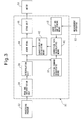
Figure 3 is a block diagram of an embodiment of a numerical control device for controlling the feed axes of the machine tool ofFigure 1 . -
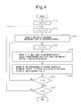
Figure 4 is a flowchart showing an example of an error measurement method. -
Figure 5 is a schematic illustration of the error measurement apparatus, explaining the error measurement method. -
Figure 6 is a schematic illustration of the error measurement apparatus, explaining the error measurement method. -
Figure 7 is a schematic illustration of the error measurement apparatus, explaining the error measurement method. -
Figure 8 is a schematic illustration of the error measurement apparatus, explaining the error measurement method. - With reference to the drawings, a preferred embodiment of the invention will be described below. A numerically controlled machine tool according to the invention is provided with a numerical control device for operating the machine toll in accordance with a processing program. With reference to
Figures 1 and2 , a horizontaltype machine tool 10 having five feed axes wherein A- and C-axes are provided on a spindle is shown. Themachine tool 10 comprises arear bed 12 fixed on a floor, acolumn 14 mounted on a top face of therear bed 12 for linear motion in a horizontal direction, i.e., X-axis direction, a head stock 15 mounted to thecolumn 14 for linear motion in both vertical and horizontal directions, i.e., Y- and Z-axis directions, abracket 18 mounted to a front face of thehead stock 16 for rotation around C-axis parallel to the Z-axis, aspindle head 20, mounted to thebracket 18 for rotation about A-axis parallel to the X-axis, for rotatably supporting aspindle 22, afront bed 24 placed side by side in the Z-axis direction relative to therear bed 12 and a table 26 mounted to thefront bed 24 so as to face thespindle 22. The Z-axis extends horizontally perpendicular to both the X- and Y-axes. Further, themachine tool 10 comprises ameasurement apparatus 52. - With reference to
Figure 3 , anumerical control device 30, for controlling the position of the feed axes of themachine tool 10, comprises a read andinterpretation unit 34 for reading and interpreting aprocessing program 32, and for calculating command speeds and positions for the respective feed axes, aninterpolation unit 36 for calculating command pulses based on the command positions and speeds in order to linearly or circularly interpolating the feed rates of the respective feed axes, position command recognizing means 38 for receiving the command pulses and recognizing the position commands to the respective feed axes, error calculating and storing means 48 for calculating errors based on measurement data which is measured by ameasurement apparatus 52 and the machine coordinates which are obtained by reading the digital scales of the respective X-, Y- and Z-axes of themachine tool 10 and for storing the obtained errors, correctiondata calculating means 40 for calculating correction data for correcting the position commands based on the position commands and the error data stored in the error calculating and storing means 48, correction pulse calculatingmeans 42 for obtaining correction pulses for correcting the position commands based on the correction data, aservo unit 46 for controlling themotors 50 of the respective feed axes and adder means 44 for outputting pulses obtained by adding the command pulses and the correction pulses. - The
measurement apparatus 52 will be described in detail. In this embodiment, themeasurement apparatus 52 comprises a laserlength measuring device 54 fitted into a tool fitting hole (not shown) defined in thespindle 22 and a plurality ofreflector mirrors 56 attached to the table 26. In this embodiment, a laser interferometer is used as the laserlength measuring device 54. Laser interferometers include, for example, a laser source for emitting a frequency stabilized helium-neon laser, a beam splitter for dividing the laser beam from the laser source into two beams, and a counter composed of, for example, a photodiode array for counting the number of interference of fringes generated by the interference between one of the two split beams and the other of the split beams reflected from thereflector mirrors 56 whereby changes in the optical pass length is measured based on the changes in the number of the interference of fringes. - The
reflector mirrors 56 comprises a retroreflector which reflects the laser beam in the original direction regardless of changes in the incident angle of the laser beam into thereflector mirrors 56. In this embodiment, thereflector mirrors 56 comprises first tofourth reflector mirrors 56a-56d secured to the four corners of apallet 28 detachably secured to the table 26. - The measurement principal of the
measurement apparatus 52 according to this embodiment will be described below. - As described above, in this embodiment, the laser
length measuring device 54 is a laser interferometer which measures, based on the changes in the number of the interference of fringes, the difference in the length (optical pass length) between one of the first to fourth reflector mirrors 56a-56d and a measuring point and between the same reflector mirror and a current measuring point base on the following equation.
Where: - ΔL: optical pass length difference
- Pi: ith measuring point
- P0: first measuring point providing a reference measuring point
- Hj: jth reflector mirror
- L(P0,Hj): the length (optical pass length) between the first measuring point and the jth reflector mirror L(Pi,Hj): the length (optical pass length) between the ith measuring point and the jth reflector mirror
- The length between the ith measuring point and the jth reflector mirror is generally expressed by the following equation.

Where: - Xi: X-coordinate of the ith measuring point (Pi)
- Xhj: X-coordinate of the jth reflector mirror (Hj)
- Yi: Y-coordinate of the ith measuring point (Pi)
- Yhj: Y-coordinate of the jth reflector mirror (Hj)
- Zi: Z-coordinate of the ith measuring point (Pi)
- Zhj: Z-coordinate of the jth reflector mirror (Hj)
- When m is the number of the measurement points, i.e., i=1 to m, if the
reflector mirrors 56 comprises four reflector mirrors, then the number of the unknown is 12+3xm (the coordinates of the four reflector mirrors provide 12 unknowns, and the coordinates of the measurement points provide 3xm unknowns). Therefore, if m=12, equation (1) can be solved by simultaneous equations. If m is larger than 12, then the number of the simultaneous equations is larger than the number of the unknowns, whereby the solution becomes redundant (different combinations of solution are provided depending on the combination of the equations). The solutions are averaged by for example least-squares method. The measured errors are stored in the error calculating and storing means 48 in the form of an error map in a processing space defined by the three orthogonal X-, Y- and Z-axes. - With reference to
Figures 4-8 , an error measurement method according to the present embodiment will be described below. - When the error measurement process is started, the parameters I and J are reset to 0 (step S10), followed by inputting 1 into J (step S12). The parameter I denotes the measurement point. The parameter J relates to the first to
fourth reflector mirrors 56a - 56d, i.e., J=1, J=2, J=3 and J=4 denote thefirst reflector mirror 56a, thesecond reflector mirror 56b, thethird reflector mirror 56c and thefourth reflector mirror 56d, respectively. - As shown in
Figure 4 , by driving the three orthogonal linear feed axes, i.e., X-, Y- and Z-axes and rotational feed axes, i.e., A- and C-axes of themachine tool 10, the laserlength measuring device 54, in particular the working section of its counter for counting the number of the interference of fringes is moved to the reference measuring point P0 so that a laser beam is emitted to the reflector mirror (J=1), i.e., thefirst reflector mirror 56a whereby the number of the interference of fringes is measured at the reference measuring point P0 (step S14). Then, 1 is added to the parameter I (step S16), followed by moving the laserlength measuring device 54 to the measuring point (P1) along thepredetermined pass 58, as shown inFigure 5 , by driving the X-, Y- and Z-feed axes (step S18), with the laser beam continuously oriented to thefirst reflector mirror 56a. At the measuring point (P1), the counted number of the interference of fringes is stored in relation to the reflector mirror (J) and the measuring point (P1) (step S20). - Then, I is compared with a predetermined integer II in order to determine whether or not the present measuring point (Pi) is the last one of the measuring points (step S22). II=4, when the program has, for example, five measuring points, as shown in
Figures 6 and8 , for each of the first to fourth reflector mirrors 56a-56d. When the measurement is not completed for all of the measuring points (No at step S22), the flowchart goes back to step S16 whereby 1 is added to I, then steps S18 and S20 are carried out again. - After the measurement is completed for all of the measuring points (Yes at step S22), J is compared with a predetermined integer JJ in order to determine whether or not the currently measured reflector mirror (J) is the last one of the reflector mirrors (step S24). If the measurement is not completed for all of the reflector mirrors (No at step S24), the flowchart goes back to step S12 whereby 1 is added to J whereby steps S14 to S22 of the measuring process are carried out for the next reflector mirror, for example, the second reflector mirror as shown in
Figure 7 (Figure 8 ). The measurement is completed for all of the reflector mirrors (Yes at step S24), the measuring process is completed. - The error calculating and storing means 48 compares the respective coordinates of Pi obtained by solving equation (1) with the machine coordinates obtained by reading the respective digital scales of the X-, Y- and Z-feed axes, whereby the errors of the respective X-, Y-and Z-axes are obtained.
- According to the present embodiment, the laser
length measuring device 54 is attached to the tool mounting hole at the end of thespindle 22, and therefore the laserlength measuring device 54 can be continuously oriented to the first to fourth reflector mirrors 56a-56d by using the three orthogonal linear feed axes, i.e., X-, Y- and Z-axes and the rotational feed axes, i.e., A- and C-axes of themachine tool 10 without providing a special tracking device, and therefore a simple and low cost error measuring apparatus is provided. Further, the laserlength measuring device 54 can be automatically attached by using a tool changer incorporated with themachine tool 10. - Although the reflector mirrors are attached to the table through the
pallet 28 in the aforementioned embodiment, the reflector mirrors may be directly attached to the table. Further, provision of thepallet 28 with the reflector mirrors 56 precedingly attached thereto enables an automatic error measurement by using a pallet changer (not shown) incorporated with themachine tool 10 and the aforementioned automatic laserlength measuring device 54. This enables programed automatic daily or seasonal error measurements. - Although the laser
length measuring device 54 comprising a laser interferometer is used in the aforementioned embodiment, the present invention is not limited to this configuration, and a laser length measuring device which can measure the absolute lengths between the reflector mirrors 56 and the laserlength measuring device 56 may be used. In this case, error measurement can be carried out with the reflector mirrors 56 including three reflector mirrors, instead four, if the positions of the mirrors are precedingly known. - If there are errors in the rotational positioning or the inclination of the rotational axis of the rotational feed axes (A- and C-axes), the errors adversely affect the measurement results. Accordingly, the machine tool is assembled while measuring so that the errors are minimized in a reference region. After the machine tool is assembled, the errors of the rotational feed axes (A-and C-axes) within the reference region is stored in order to enable correction during measurement of the liner feed axes (X-, Y- and Z-axes).
- In particular, the errors in position and inclination are stored in relation to the rotational angles of the rotational feed axes (A- and C-axes), whereby the feed axes (X-, Y- and Z-axes) are corrected depending on the position errors, and the rotational feed axes are corrected depending on the inclination errors. If the inclination errors of the rotational feed axes (A-and C-axes) are small, declinations of the referent point of the laser length measuring device are stored in relation to the rotational angles of the rotational feed axes (A- and C-axes), whereby only the liner feed axes (X-, Y- and Z-axes) can be corrected so as to position a point of reference of the laser length measuring device at a desired coordinate value.
- When measuring the liner feed axes (X-, Y- and Z-axes), by correcting the errors of the rotational axes (A- and C-axes) depending on the rotational positions of the rotational feed axes (A- and C-axes), the errors of the liner feed axes (X-, Y- and Z-axes) can be efficiently measured.
-
- 10
- Machine Tool
- 12
- Rear Bed
- 14
- Column
- 16
- Head Stock
- 18
- Bracket
- 22
- Spindle
- 24
- Front Bed
- 26
- Table
- 28
- Pallet
- 30
- Numerical Control Device
- 32
- Processing Program
- 34
- Read and Interpretation Unit
- 36
- Interpolation Unit
- 46
- Servo Unit
- 50
- Feed Motor
- 52
- Measurement Apparatus
- 54
- Laser Length Device
- 56
- Reflector Mirror
- 56a
- First Reflector Mirror
- 56b
- Second Reflector Mirror
- 56c
- Third Reflector Mirror
- 56d
- Fourth Reflector Mirror
Claims (8)
- A method of measuring an error in linear feed axes of a multi feed axis machine tool having at least two rotational feed axes as well as three orthogonal linear feed axes, i.e., X-, Y- and Z-axes, the method comprising the steps of:attaching at least first to third reflector mirrors to a table of the machine tool;attaching a laser length measuring device to an end of a spindle of the machine tool;moving the laser length measuring device to predetermined measuring points by driving the three linear feed axes;orienting the laser length measuring device to the reflector mirrors by driving the at least two rotational feed axes to measure the lengths between the first to third reflector mirrors and the laser length measuring device whereby the coordinates of the respective measuring points are calculated; andcomparing the machine coordinates of the machine tool at the measuring points with the calculated coordinates of the measuring points whereby errors of the linear feed axes of the machine tool are obtained.
- A method according to claim 1, further comprising a step of attaching a fourth reflector mirror to the table of the machine tool, wherein the laser length measuring device is a laser interferometer and the coordinates of the respective measuring points are calculated by measuring the changes in the lengths between the first to fourth reflector mirrors and the laser interferometer.
- A method according to claim 1, wherein the laser length measuring device measures the absolute lengths between the reflector mirrors and the laser length measuring device.
- A method according to any one of the preceding claims, wherein the reflector mirrors comprise retroreflectors.
- A machine tool with a table to which a workpiece is attached, a spindle, supported for rotation, for holding a tool, linear feed axes for relatively moving the table and the spindle in three orthogonal X-, Y-, and Z-axes directions and at at least two rotational feed axes, the machine tool comprising:a laser length measuring device attached to an end of a spindle; andfirst to third reflector mirrors attached to a table of the machine tool;wherein the laser length measuring device is moved to predetermined measuring points by driving the three linear feed axes, and oriented to the reflector mirrors by driving the at least two rotational feed axes to measure the lengths between the first to third reflector mirrors and the laser length measuring device whereby the coordinates of the respective measuring points are calculated, the calculated coordinates of the measuring points being compared with the machine coordinates of the machine tool at the measuring points whereby errors of the linear feed axes of the machine tool are measured.
- A machine tool according to claim 5, further comprising a fourth reflector mirror to the table of the machine tool, wherein the laser length measuring device comprises a laser interferometer.
- A machine tool according to claim 5, wherein the laser length measuring device measures the absolute lengths between the reflector mirrors and the laser length measuring device.
- A machine tool according to any one of claims 5-7, wherein the reflector mirrors comprise retroreflectors.
Applications Claiming Priority (1)
| Application Number | Priority Date | Filing Date | Title |
|---|---|---|---|
| PCT/JP2011/077682 WO2013080336A1 (en) | 2011-11-30 | 2011-11-30 | Error measurement method and machine tool |
Publications (2)
| Publication Number | Publication Date |
|---|---|
| EP2786839A1 true EP2786839A1 (en) | 2014-10-08 |
| EP2786839A4 EP2786839A4 (en) | 2015-10-21 |
Family
ID=48534855
Family Applications (1)
| Application Number | Title | Priority Date | Filing Date |
|---|---|---|---|
| EP11876460.4A Withdrawn EP2786839A4 (en) | 2011-11-30 | 2011-11-30 | ERROR MEASURING METHOD AND TOOL MACHINE |
Country Status (4)
| Country | Link |
|---|---|
| US (1) | US9506745B2 (en) |
| EP (1) | EP2786839A4 (en) |
| JP (1) | JP5745646B2 (en) |
| WO (1) | WO2013080336A1 (en) |
Cited By (2)
| Publication number | Priority date | Publication date | Assignee | Title |
|---|---|---|---|---|
| DE102017003257A1 (en) | 2017-03-31 | 2018-10-04 | Institut für innovative Technologien, Technologietransfer, Ausbildung und berufsbegleitende Weiterbildung (ITW) e. V. | Method for detecting position deviations of an axis system of a machine tool and apparatus for carrying out this method |
| EP4524512A1 (en) | 2023-09-15 | 2025-03-19 | Dr. Johannes Heidenhain GmbH | Calibration artifact |
Families Citing this family (7)
| Publication number | Priority date | Publication date | Assignee | Title |
|---|---|---|---|---|
| JP6130242B2 (en) * | 2013-06-26 | 2017-05-17 | Dmg森精機株式会社 | Machine tool with measuring device |
| CN104634248B (en) * | 2015-02-04 | 2017-02-22 | 西安理工大学 | Revolving shaft calibration method under binocular vision |
| CN105538038B (en) * | 2016-01-27 | 2018-01-16 | 清华大学 | Lathe translation shaft geometric error discrimination method |
| EP3745223B1 (en) * | 2018-01-22 | 2023-03-15 | Fundación Tekniker | Method for self-verification of mechatronic systems |
| CN113970293B (en) * | 2021-10-15 | 2024-01-05 | 湖北三江航天险峰电子信息有限公司 | Accurate on-machine measurement method and system for point laser |
| CN117124137B (en) * | 2023-10-23 | 2024-03-15 | 成都飞机工业(集团)有限责任公司 | Measuring device and measuring method for zero point positioning of machine tool rotating shaft |
| CN118081480B (en) * | 2024-04-29 | 2024-07-16 | 浙江大学 | A radial rotation error measurement method of electric spindle based on vibration response reconstruction |
Family Cites Families (7)
| Publication number | Priority date | Publication date | Assignee | Title |
|---|---|---|---|---|
| JP3394972B2 (en) * | 1994-03-14 | 2003-04-07 | 独立行政法人産業技術総合研究所 | Automatic machine tool |
| US5508806A (en) * | 1995-02-13 | 1996-04-16 | Hewlett-Packard Company | Apparatus and method for making rotary calibrations of a machine tool table |
| US5808740A (en) * | 1995-08-31 | 1998-09-15 | Sokkia Company Limited | Multiaxis distance measurement device for NC machine tools |
| JP3621774B2 (en) * | 1995-10-31 | 2005-02-16 | 株式会社ソキア | Multi-axis measuring machine for NC machine tools |
| JP5030653B2 (en) | 2007-04-20 | 2012-09-19 | 株式会社牧野フライス製作所 | Numerical control machine tool and numerical control device |
| DE102010021839A1 (en) * | 2010-05-28 | 2011-12-01 | Dörries Scharmann Technologie GmbH | Method for machine measurement |
| DE102010039948B4 (en) * | 2010-08-30 | 2020-10-22 | Carl Zeiss Ag | Measuring unit, measuring system and method for determining a relative position and relative orientation |
-
2011
- 2011-11-30 US US14/361,656 patent/US9506745B2/en active Active
- 2011-11-30 JP JP2013546904A patent/JP5745646B2/en active Active
- 2011-11-30 EP EP11876460.4A patent/EP2786839A4/en not_active Withdrawn
- 2011-11-30 WO PCT/JP2011/077682 patent/WO2013080336A1/en not_active Ceased
Cited By (3)
| Publication number | Priority date | Publication date | Assignee | Title |
|---|---|---|---|---|
| DE102017003257A1 (en) | 2017-03-31 | 2018-10-04 | Institut für innovative Technologien, Technologietransfer, Ausbildung und berufsbegleitende Weiterbildung (ITW) e. V. | Method for detecting position deviations of an axis system of a machine tool and apparatus for carrying out this method |
| EP4524512A1 (en) | 2023-09-15 | 2025-03-19 | Dr. Johannes Heidenhain GmbH | Calibration artifact |
| DE102023208961A1 (en) | 2023-09-15 | 2025-03-20 | Dr. Johannes Heidenhain Gmbh | Calibration artifact |
Also Published As
| Publication number | Publication date |
|---|---|
| US9506745B2 (en) | 2016-11-29 |
| EP2786839A4 (en) | 2015-10-21 |
| US20140355002A1 (en) | 2014-12-04 |
| JP5745646B2 (en) | 2015-07-08 |
| WO2013080336A1 (en) | 2013-06-06 |
| JPWO2013080336A1 (en) | 2015-04-27 |
Similar Documents
| Publication | Publication Date | Title |
|---|---|---|
| US9506745B2 (en) | Error measurement method and machine tool | |
| US4714339A (en) | Three and five axis laser tracking systems | |
| US8786243B2 (en) | Method and device for preparing error map and numerically controlled machine tool having error map preparation function | |
| CN114248154B (en) | Five-axis machine tool space positioning precision detection device and method | |
| US8452564B2 (en) | Method of determining geometric errors in a machine tool or measuring machine | |
| US6973738B2 (en) | Measuring method and device, machine tool having such device, and work processing method | |
| KR101906942B1 (en) | Calibration of a coordinate measuring machine using a calibration laser head at the tool centre point | |
| US8006398B2 (en) | Method for scanning the surface of a workpiece | |
| US8659763B2 (en) | Method for machine measurement | |
| KR102935386B1 (en) | Method for calibrating a measuring probe in a gear cutting machine | |
| US6865498B2 (en) | System for calibrating the axes on a computer numeric controlled machining system and method thereof | |
| JP2510216B2 (en) | Method for calibrating sensors in industrial robots | |
| CN102322796A (en) | Laser detection device and method for gear parameters | |
| WO2006109094A1 (en) | Method of error correction | |
| JP4571256B2 (en) | Shape accuracy measuring device by sequential two-point method and laser displacement meter interval measuring method for shape accuracy measurement by sequential two-point method | |
| US9658610B2 (en) | Displacement and position measurement in machine tool | |
| CN101352817A (en) | Method of measuring position detection error in machine tool | |
| JP6147022B2 (en) | Spatial accuracy measuring method and spatial accuracy measuring apparatus for machine tool | |
| JP2755346B2 (en) | Method and apparatus for measuring motion accuracy of automatic machine tool | |
| EP2818949A1 (en) | Computer numerical control machining center with integrated coordinate measuring unit and method for measuring a workpiece in situ | |
| CN115655114B (en) | A compensation method and compensation device based on a long-length calibration device | |
| CN118143739A (en) | Machine tool Blaine error measurement method, device and machine tool straightness measurement error compensation method | |
| JPH0435004B2 (en) |
Legal Events
| Date | Code | Title | Description |
|---|---|---|---|
| PUAI | Public reference made under article 153(3) epc to a published international application that has entered the european phase |
Free format text: ORIGINAL CODE: 0009012 |
|
| 17P | Request for examination filed |
Effective date: 20140606 |
|
| AK | Designated contracting states |
Kind code of ref document: A1 Designated state(s): AL AT BE BG CH CY CZ DE DK EE ES FI FR GB GR HR HU IE IS IT LI LT LU LV MC MK MT NL NO PL PT RO RS SE SI SK SM TR |
|
| DAX | Request for extension of the european patent (deleted) | ||
| RA4 | Supplementary search report drawn up and despatched (corrected) |
Effective date: 20150922 |
|
| RIC1 | Information provided on ipc code assigned before grant |
Ipc: G05B 19/401 20060101ALI20150916BHEP Ipc: B23Q 17/24 20060101ALI20150916BHEP Ipc: B23Q 17/00 20060101AFI20150916BHEP Ipc: B23Q 1/48 20060101ALI20150916BHEP Ipc: G01B 11/00 20060101ALI20150916BHEP |
|
| STAA | Information on the status of an ep patent application or granted ep patent |
Free format text: STATUS: THE APPLICATION IS DEEMED TO BE WITHDRAWN |
|
| 18D | Application deemed to be withdrawn |
Effective date: 20160420 |