EP2784811A2 - Heat pipe sink with heating unit - Google Patents
Heat pipe sink with heating unit Download PDFInfo
- Publication number
- EP2784811A2 EP2784811A2 EP20140161555 EP14161555A EP2784811A2 EP 2784811 A2 EP2784811 A2 EP 2784811A2 EP 20140161555 EP20140161555 EP 20140161555 EP 14161555 A EP14161555 A EP 14161555A EP 2784811 A2 EP2784811 A2 EP 2784811A2
- Authority
- EP
- European Patent Office
- Prior art keywords
- heat
- heat pipes
- pipes
- fins
- subset
- Prior art date
- Legal status (The legal status is an assumption and is not a legal conclusion. Google has not performed a legal analysis and makes no representation as to the accuracy of the status listed.)
- Granted
Links
Images




Classifications
-
- H—ELECTRICITY
- H10—SEMICONDUCTOR DEVICES; ELECTRIC SOLID-STATE DEVICES NOT OTHERWISE PROVIDED FOR
- H10W—GENERIC PACKAGES, INTERCONNECTIONS, CONNECTORS OR OTHER CONSTRUCTIONAL DETAILS OF DEVICES COVERED BY CLASS H10
- H10W40/00—Arrangements for thermal protection or thermal control
- H10W40/40—Arrangements for thermal protection or thermal control involving heat exchange by flowing fluids
- H10W40/47—Arrangements for thermal protection or thermal control involving heat exchange by flowing fluids by flowing liquids, e.g. forced water cooling
-
- F—MECHANICAL ENGINEERING; LIGHTING; HEATING; WEAPONS; BLASTING
- F28—HEAT EXCHANGE IN GENERAL
- F28D—HEAT-EXCHANGE APPARATUS, NOT PROVIDED FOR IN ANOTHER SUBCLASS, IN WHICH THE HEAT-EXCHANGE MEDIA DO NOT COME INTO DIRECT CONTACT
- F28D15/00—Heat-exchange apparatus with the intermediate heat-transfer medium in closed tubes passing into or through the conduit walls ; Heat-exchange apparatus employing intermediate heat-transfer medium or bodies
- F28D15/02—Heat-exchange apparatus with the intermediate heat-transfer medium in closed tubes passing into or through the conduit walls ; Heat-exchange apparatus employing intermediate heat-transfer medium or bodies in which the medium condenses and evaporates, e.g. heat pipes
-
- F—MECHANICAL ENGINEERING; LIGHTING; HEATING; WEAPONS; BLASTING
- F28—HEAT EXCHANGE IN GENERAL
- F28D—HEAT-EXCHANGE APPARATUS, NOT PROVIDED FOR IN ANOTHER SUBCLASS, IN WHICH THE HEAT-EXCHANGE MEDIA DO NOT COME INTO DIRECT CONTACT
- F28D15/00—Heat-exchange apparatus with the intermediate heat-transfer medium in closed tubes passing into or through the conduit walls ; Heat-exchange apparatus employing intermediate heat-transfer medium or bodies
- F28D15/02—Heat-exchange apparatus with the intermediate heat-transfer medium in closed tubes passing into or through the conduit walls ; Heat-exchange apparatus employing intermediate heat-transfer medium or bodies in which the medium condenses and evaporates, e.g. heat pipes
- F28D15/0275—Arrangements for coupling heat-pipes together or with other structures, e.g. with base blocks; Heat pipe cores
-
- F—MECHANICAL ENGINEERING; LIGHTING; HEATING; WEAPONS; BLASTING
- F28—HEAT EXCHANGE IN GENERAL
- F28F—DETAILS OF HEAT-EXCHANGE AND HEAT-TRANSFER APPARATUS, OF GENERAL APPLICATION
- F28F1/00—Tubular elements; Assemblies of tubular elements
- F28F1/10—Tubular elements and assemblies thereof with means for increasing heat-transfer area, e.g. with fins, with projections, with recesses
- F28F1/12—Tubular elements and assemblies thereof with means for increasing heat-transfer area, e.g. with fins, with projections, with recesses the means being only outside the tubular element
- F28F1/24—Tubular elements and assemblies thereof with means for increasing heat-transfer area, e.g. with fins, with projections, with recesses the means being only outside the tubular element and extending transversely
- F28F1/32—Tubular elements and assemblies thereof with means for increasing heat-transfer area, e.g. with fins, with projections, with recesses the means being only outside the tubular element and extending transversely the means having portions engaging further tubular elements
-
- H—ELECTRICITY
- H10—SEMICONDUCTOR DEVICES; ELECTRIC SOLID-STATE DEVICES NOT OTHERWISE PROVIDED FOR
- H10W—GENERIC PACKAGES, INTERCONNECTIONS, CONNECTORS OR OTHER CONSTRUCTIONAL DETAILS OF DEVICES COVERED BY CLASS H10
- H10W40/00—Arrangements for thermal protection or thermal control
- H10W40/10—Arrangements for heating
-
- H—ELECTRICITY
- H10—SEMICONDUCTOR DEVICES; ELECTRIC SOLID-STATE DEVICES NOT OTHERWISE PROVIDED FOR
- H10W—GENERIC PACKAGES, INTERCONNECTIONS, CONNECTORS OR OTHER CONSTRUCTIONAL DETAILS OF DEVICES COVERED BY CLASS H10
- H10W40/00—Arrangements for thermal protection or thermal control
- H10W40/70—Fillings or auxiliary members in containers or in encapsulations for thermal protection or control
- H10W40/73—Fillings or auxiliary members in containers or in encapsulations for thermal protection or control for cooling by change of state
-
- H—ELECTRICITY
- H10—SEMICONDUCTOR DEVICES; ELECTRIC SOLID-STATE DEVICES NOT OTHERWISE PROVIDED FOR
- H10W—GENERIC PACKAGES, INTERCONNECTIONS, CONNECTORS OR OTHER CONSTRUCTIONAL DETAILS OF DEVICES COVERED BY CLASS H10
- H10W40/00—Arrangements for thermal protection or thermal control
- H10W40/20—Arrangements for cooling
- H10W40/22—Arrangements for cooling characterised by their shape, e.g. having conical or cylindrical projections
- H10W40/226—Arrangements for cooling characterised by their shape, e.g. having conical or cylindrical projections characterised by projecting parts, e.g. fins to increase surface area
Definitions
- the present invention pertains to heat sinks and, in particular, to heat sink devices having a plurality of heat pipes.
- the heat generated by the semiconductor device is transferred away from the device and dissipated.
- a number of techniques are used to transfer and dissipate the heat from semiconductor devices.
- heat pipes have been used to move heat away from semiconductor devices and fins have been used with the heat pipes to dissipate the transferred heat to the air.
- Heat pipes are enclosed pipes that transfer heat through the evaporation and condensation of a fluid contained in the heat pipe.
- a typical heat pipe includes an evaporator section which is located near a heat source (i.e. the semiconductor device) and a condenser section which is located away from the heat source. The heat from the heat source causes fluid located in the evaporator section to evaporate. The vapor then moves to the condenser section, thus transferring heat generated by the heat source to the condenser section.
- the condenser section of a heat pipe is often constructed to be in thermal contact with a series of metallic fins.
- the heat of the vapor in the condenser section is transferred into the fins where the large surface area of the fins aids in dissipating the heat into the air.
- Heat sinks have also used a blower to blow air over the fins to further aid the dissipation process.
- the vapor cools off and condenses.
- the condensed fluid is then transferred back to the evaporator section to be heated up again. The cycle of evaporation and condensation continues, thus transferring and dissipating the heat generated by the heat source, and thereby cooling the heat source.
- the use of heat pipes with heat sinks has not been without difficulty.
- the liquid in the heat pipes can freeze.
- the evaporator sections of the heat pipes are no longer able to evaporate liquid and thus, the heat pipes become unusable until the frozen liquid in the condenser sections of the heat pipes is thawed.
- Liquids with a wide operating range e.g., a lower freezing temperature
- a heat sink in one embodiment, includes a cold plate, a plurality of heat pipes, a plurality of fins, and a heating unit.
- the cold plate has a first surface adapted to thermally couple to a heat source.
- Each of the heat pipes has an evaporator section thermally coupled to the cold plate and a condenser section coupled to the evaporator section.
- the plurality of fins are thermally coupled to the condenser sections of the plurality of heat pipes.
- the heating unit is adapted to heat condenser sections of a subset of the plurality of heat pipes.
- a method of heating heat pipes is provided.
- the method includes providing a cold plate having a first surface adapted to thermally couple to a heat source; providing a plurality of heat pipes, each of the heat pipes having an evaporator section thermally coupled to the cold plate and a condenser section coupled to the evaporator section; providing a plurality of fins thermally coupled to the condenser sections of the plurality of heat pipes; and heating condenser sections of a subset of the plurality of heat pipes.
- the method can further comprise selectively providing power to heat the subset of the plurality of heat pipes.
- the method can further comprise providing one or more resistive elements disposed around the condenser sections of the subset of the plurality of heat pipes, and selectively providing power to the one or more resistive elements so as to heat the one or more resistive elements.
- the method can further comprise wrapping each of the one or more resistive elements around a respective one of the heat pipes of the subset of the plurality of heat pipes.
- the method can further comprise providing a plurality of heating devices, wherein each of the plurality of heating devices is attached to respective a respective one of the fins nearby one of the heat pipes of the subset of the plurality of heat pipes, and selectively providing power to the heating devices to heat the heating devices.
- the method can further comprise providing a second plurality of heating devices, wherein each of the plurality of second heating devices is attached to a respective one of the fins nearby a second one of the heat pipes of the subset of the plurality of heat pipes.
- the method can further comprise providing one or more radiant heaters adapted to apply radiant energy to the condenser sections of the plurality of heat pipes, wherein the condenser sections of the subset of heat pipes are provided with a means of increasing absorption of radiant energy.
- the means of increasing absorption of radiant energy is dark coloring of the subset of heat pipes.
- the one or more radiant heaters are disposed on opposite sides of the fins.
- the method can further comprise providing one or more tubular heaters which each extend through the plurality of fins, and selectively providing power to at least one of the tubular heaters.
- Each of the one or more tubular heaters includes a hollow pipe extending through the plurality of fins and a heating element disposed inside the hollow pipe.
- the method can further comprise providing at least one temperature sensor adapted to sense at least one of a temperature of the heat source, a temperature of the condenser sections of the plurality of heat pipes, and an ambient temperature, and controlling the heating unit to heat the subset of the plurality of heat pipes based on at least one of the temperature of the heat source, the temperature of the condenser sections of the plurality of heat pipes, and the ambient temperature.
- the method can further comprise determining an amount of heat to apply to the subset of the plurality of heat pipes, and controlling the amount of heat by controlling at least one of a number of heat pipes heat is applied to, a duration in which power is applied, and an amount of power which is applied.
- the plurality of fins can each include at least one perforation which reduces an amount the plurality of fins dissipates heat of a selected one or more of the heat pipes of the plurality of heat pipes with respect to the remaining heat pipes of the plurality of heat pipes.
- heating a heat pipe and similar terms such as “heating a condenser section of the heat pipe” shall mean that heat is provided to the heat pipe in at least an amount sufficient to maintain a working fluid included in the heat pipe in liquid form when in would otherwise freeze or, in the case that the working fluid is frozen, to thaw the working fluid.
- the heat may be provided directly or indirectly to the heat pipe, i.e., through one or more intermediate parts or components.
- FIG. 1 is an isometric schematic of an exemplary embodiment of a heat sink 5 implemented according to principles of the present invention.
- FIGS. 2 and 3 are side view and end view schematics, respectively, of the heat sink 5 illustrated in FIG. 1 .
- FIG. 4 is a side view schematic of an exemplary heat pipe 20 which is adapted for use in the heat sink 5 illustrated in FIGS. 1-3 .
- the heat sink 5 includes a plurality of fins 10, a plurality of heat pipes 20, and at least one cold plate 30.
- the heat pipes 20 each include an evaporator section 26, a bend section 24, and a condenser section 22 (see FIG. 4 ).
- the evaporator section 26 is arranged substantially vertically and connected to the cold plate 30.
- the heat pipes 20 also include the condenser section 22 which is inclined with respect to a horizontal plane and extends through a plurality of fins 10.
- the evaporator section 26 and the condenser section 22 of each heat pipe 20 are connected by a single straight bend section 24.
- the evaporator section 26 and the condenser section 22 are each substantially straight pieces of piping.
- the evaporator sections 26 of the heat pipes 20 extend in parallel with each other and the condenser sections 22 of the heat pipes 20 extend in parallel with each other.
- the bend section 24 includes a piece of piping having a single straight bend.
- single straight bend means a single bend with a substantially constant radius and without a substantial twist or skew.
- the geometry of each heat pipe 20 has minimal complexity.
- a plurality of heat pipes 20 are thermally coupled to the cold plate 30.
- FIGS. 1-3 show sixteen heat pipes 20 thermally coupled to the cold plate 30, the present invention is not limited thereto. It is contemplated that any number of heat pipes 20 greater than two can be thermally coupled to the cold plate 30 while remaining within the scope of the invention.
- the vertical evaporator sections 26 of adjacent heat pipes 20 have different lengths. As such, the condenser sections 22 of adjacent heat pipes 20 are spaced apart from each other and extend through different areas of the fins 10. As illustrated in FIG. 1 , the heat pipes 20 are spread across the area of the fins 10. Spreading out the locations where the heat pipes 20 extend through the fins 10 increases the efficiency of the fins 10 in dissipating the heat of the heat pipes 20 as compared to a configuration wherein the heat pipes 20 extend through the same area of the fins 10.
- the condenser section 22 of the heat pipe 20 is inclined with respect to a horizontal plane by an angle 27 (see FIG. 4 ).
- the angle 27 may be within a range of about 5-40 degrees, or preferably about 5-20 degrees.
- the evaporator section 26 of the heat pipes 20 and the cold plate 30 are arranged substantially vertically.
- the condenser section 22 of the heat pipes 20 and the cold plate 30 may also be tilted with respect to a vertical axis.
- the heat pipes 20 are inserted into an upper surface of the cold plate 30.
- the heat pipes 20 may be connected to the cold plate 30 in any suitable manner which thermally couples them while remaining within the scope of the invention.
- the cold plate 30 may include an interior chamber (e.g. a vapor chamber) and the heat pipes 20 may be coupled to an upper surface of the cold plate 30 and be fluidly connected with the interior chamber of the cold plate 30.
- the heat pipes 20 may be attached to the cold plate 30 by, for example and without limitation, welding, soldering, or by using a suitable thermally conductive adhesive.
- the fins 10 are spaced apart from each other.
- the number, spacing, size, and/or thickness of the fins 10 can be varied.
- the number, spacing, size, and/or thickness of the fins 10 can be optimized based on an expected thermal loading of different areas of the fins 10.
- the cold plate 30 is adapted to thermally couple with a heat source (see FIG. 7 ).
- the cold plate 30 may be thermally coupled with the heat source in any suitable manner such as, without limitation, by a thermally conductive adhesive.
- FIG. 4 is a side view schematic of an exemplary heat pipe 20 according to principles of the present invention.
- the heat pipe 20 shown in FIG. 4 is readily adapted for use in the heat sinks 5 shown in FIGS. 1-3 .
- the heat pipes 20 shown in FIGS. 1-3 are similar except that lengths of the evaporator sections 26 of the heat pipes 20 are varied.
- the evaporator sections 26 of the heat pipes 20 are coupled with the cold plate 30.
- the evaporator sections 26 of the heat pipes 20 can be inserted into the cold plate 30.
- the heat pipe 20 operates to transfer heat from the evaporator section 26 to the condenser section 22 through the evaporation and condensation of a liquid included in the heat pipe 20. More particularly, when the evaporator section 26 of the heat pipe 20 is heated, the liquid evaporates into a vapor. The vapor moves to the condenser section 22 where it cools and condenses. The liquid then moves back to the evaporator section 26 with the assistance of gravity. The cycle of evaporation and condensation transfers thermal energy from the evaporator section 26 to the condenser section 22 of the heat pipe 20. Fins 10 thermally coupled to the condenser section 22 assist to dissipate the heat from the condenser section 22.
- the heat pipes 20 may also include a wick which is formed on an interior of the heat pipe 20 to assist with moving the condensed liquid to the evaporator section 26.
- the wick may extend through the full length of the heat pipe 20 or through a portion of the heat pipe 20.
- the condenser section 22 is inclined with respect to horizontal by an angle 27 so as to utilize gravity to assist in returning condensed liquid to the evaporator section 26.
- the angle 27 may be, for example and without limitation, in a range of 5-40 degrees, and preferably within a range of 5-20 degrees.
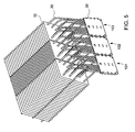
- FIGS. 5 and 6 illustrate arrangements of heat sinks in accordance with embodiments of the present inventive concept.
- a plurality of heat sinks 101, 102, and 103 are arranged together so as to dissipate heat from one or more heat sources.
- heat sinks 101, 102, and 103 each include a cold plate 30, a plurality of heat pipes 20 attached to the cold plate 30, and a plurality of fins 10 attached to a condenser section of the heat pipes 20.
- the heat sinks 101, 102, and 103 are similar to the heat sink 5 shown in FIGS. 1-3 . However, characteristics of the heat sinks 101, 102, and 103 are varied.
- heat sinks 101 and 103 have similar characteristics, but heat sink 102 has a higher density of fins 10 (i.e. more fins per unit of length) thermally coupled to the condenser section of the heat pipes 20 than heat sinks 101 and 103, thus allowing heat sink 102 to dissipate a larger amount of heat than heat sinks 101 or 103.
- heat sink 102 has a higher density of fins 10 (i.e. more fins per unit of length) thermally coupled to the condenser section of the heat pipes 20 than heat sinks 101 and 103, thus allowing heat sink 102 to dissipate a larger amount of heat than heat sinks 101 or 103.
- the heat sinks 101, 102, and 103 are arranged such that their respective cold plates 30 are coplanar and adjacent to each other.
- the coplanar arrangement allows multiple cold plates 30 to be easily thermally coupled to a heat source (such as a number of power semiconductors).
- a thermally conductive member such as, without limitation, a metal piece or a heat pipe, can be attached across the cold plates 30 of heat sinks 101, 102, and 103 so as to both attach the heat sinks 101, 102, and 103 to each other and to thermally couple the heat sinks 101, 102, and 103 to one or more heat sources.
- heat sinks 201, 202, and 203 are arranged together so as to dissipate heat from one or more heat sources.
- heat sinks 201 and 203 are similar to each other and each include a cold plate 30, a plurality of heat pipes 20 thermally coupled with the cold plate 30, and a plurality of fins 10 thermally coupled with a condenser section of the heat pipes 20.
- Heat sink 202 is similar to heat sinks 201 and 203 except that heat sink 202 uses heat pipes 120 which have a longer condenser section than heat pipes 20.
- heat sink 202 includes a larger number of fins 10 than heat sinks 201 and 203. The heat pipes 120 with a longer condenser section and larger number of fins 10 allow heat sink 202 to dissipate more heat than heat sinks 201 or 203.
- FIGS. 5 and 6 include multiple heat sinks arranged together while varying the density of fins coupled to the condenser section of the heat pipes or varying the length of the condenser section of the heat pipes and the number of fins coupled to the condenser section of the heat pipes, other characteristics of the heat sinks, such as, for example and without limitation, the number of heat pipes used in each heat sink or the size of each heat sink, the material used in the cold plate and/or fins, the working fluid(s) in the heat pipes, or the material used in the heat pipes can be varied while remaining within the scope of the invention.
- Characteristics of each heat sink may be determined based on, for example and without limitation, expected thermal loading. For example, if it is anticipated that a heat source or arrangement of heat sources will provide a higher thermal load at a central area and a lower thermal load at an outer area, an arrangement of heat sinks which provides a higher heat dissipation to a central area, such as, for example, the arrangements shown in FIGS. 5 and 6 , can be used. While the embodiments of FIGS. 5 and 6 can dissipate a higher thermal load in a central area of a heat source or heat sources, heat sinks can be arranged with varying characteristics determined to dissipate various thermal loads while remaining within the scope of the invention.
- FIG. 7 illustrates a system in accordance with principles of the present invention according to one exemplary embodiment.
- the system includes a heat sink 5 including heat pipes 20, cold plate 30, and fins 10 which are similar to the heat sink 5 described above with respect to FIGS. 1-3 .
- the arrangements of heat sinks in the embodiments shown in FIGS. 5-6 can also be adapted for use in the system shown in FIG. 7 .
- the system additionally includes an enclosure 100, a blower 110, a thermally conductive adhesive 120, a circuit board 130, and a heat source 140.
- the evaporator section 26 of the heat pipes 20 is disposed primarily inside the enclosure 100 and the condenser section 22 of the heat pipes 20 is disposed primarily outside the enclosure 100.
- the heat source 140 which is in close proximity with the evaporator section 26 of the heat pipes 20, may be shielded from the outside environment.
- the blower 110 is adapted to blow air across the fins 10. Including the blower 110 increases the amount of heat dissipated by the fins 10 compared to a heat sink 5 which operates through only natural convection. In the embodiment shown in FIG. 7 , the blower 110 is disposed below the fins 10. However, it is contemplated that the blower 110 may be disposed at any suitable location to blow air over the fins 10 without departing from the scope of the invention. Furthermore, it is contemplated that the blower 110 may be omitted without departing from the scope of the invention.
- the heat source 140 is thermally coupled to the cold plate 30 with a thermally conductive adhesive 120.
- the heat source 140 may be coupled to the cold plate 30 in any suitable manner which thermally couples the heat source 140 and the cold plate 30 while remaining within the scope of the invention.
- the heat source 140 may be any type of device that generates heat, such as, without limitation, semiconductor devices which generate a large amount of heat.
- the heat source 140 is a power semiconductor such as an insulated gate bipolar transistor (IGBT).
- IGBT insulated gate bipolar transistor
- the heat source 140 may be a variety of different semiconductor devices or other devices which generate heat.
- FIGS. 8A and 8B are side views of heat sinks 6a and 6b implemented according to alternative exemplary embodiments of the present invention.
- the heat sink 6a illustrated in FIG. 8A includes fins 10, heat pipes 20, and a cold plate 30 arranged similar to the heat sink 5 described above with respect to FIG. 1 .
- the heat sink 6 further includes a heating unit 40.
- the heating unit 40 includes a control unit 41 which is electrically connected to a first resistive element 42a.
- the first resistive element 42a is wrapped around the condenser section of the one of the heat pipes 20.
- the control unit 41 applies power to the first resistive element 42a so as to heat the first resistive element 42a, thus heating the condenser section of the heat pipe 20 that the first resistive element 42a is wrapped around.
- FIG. 8A illustrates one resistive element 42a wrapped around the condenser section of one of the heat pipes 20
- the heat sink 6b illustrated in FIG. 8B includes multiple resistive elements 42a, 42b, and 42c, each operatively coupled to the control unit 41.
- the multiple resistive elements 42a, 42b, and 42c are used to heat multiple heat pipes 20.
- control unit 41 may further selectively apply power to a subset of the resistive elements so as to control the number of heat pipes 20 that are heated.
- the heating unit 40 can prevent the liquid used in the subset of heat pipes 20 from freezing in the condenser section, thus allowing the subset of heat pipes 20 to remain operable.
- the heating unit 40 can melt liquid that is already frozen in the condenser section.
- the heating unit 40 can prevent a heat source coupled to the heat sink 6 from being exposed to too wide a range of temperatures (e.g. when the liquid in the heat pipes 20 is much colder than the temperature of the heat source).
- the heating unit 40 allows liquids which have a narrower range of operation (e.g. liquids which freeze at a higher temperature) to be used in the heat pipes 20.
- FIGS. 9A and 9B are side views of heat sinks 7a and 7b implemented according to a further alternative exemplary embodiment of the present invention.
- the heat sink 7a illustrated in FIG. 9A includes fins 10, heat pipes 20, and a cold plate 30 arranged similar to the heat sink 5 described above with respect to FIG. 1 .
- the heat sink 7a further includes a heating unit 50.
- the heating unit 50 includes a control unit 51 which is electrically connected to one or more heaters 52a.
- the heaters 52a are each attached to one of the fins 10 nearby a respective heat pipe 20a.
- the control unit 51 applies power to selected heaters 52a so as to heat the selected heat pipe 20a. While FIG. 9A illustrates a plurality of heaters 52 disposed on the fins 10 in the vicinity of one of the heat pipes 20a, it will be understood that multiple sets of heaters may be used to heat multiple different heat pipes. For example, as illustrated in FIG.
- the heating unit 50 includes a first set of heaters 52a disposed nearby a first heat pipe 20a, a second set of heaters 52b disposed nearby a second heat pipe 52b, and a third set of heaters 52c disposed nearby a third heat pipe 20c.
- the control unit 41 may further selectively apply power to a subset of the heaters 52a, 52b, and/or 52c so as to control the number of heat pipes that are heated.
- each of heaters 52a are closer to the respective heat pipe 20a than any other heat pipe.
- Each of the heaters 52a may also be located within a range of about 1-4 cm of the respective heat pipe 20a. However, the distance of the heaters 52a from the respective heat pipe 20a can be suitably changed based on, for example, changes in the scale of the heat sink.
- FIG. 10 is a side view of a heat sink 8 implemented according to a further exemplary embodiment of the present invention.
- the heat sink 8 illustrated in FIG. 10 includes fins 10, heat pipes 20, and a cold plate 30 arranged similar to the heat sink 5 described above with respect to FIG. 1 .
- the heat sink 6 further includes a heating unit 60.
- the heating unit 60 includes a control unit 61 which is electrically connected to radiant heaters 62.
- the control unit 61 applies power to the radiant heaters 62, thus causing the radiant heaters 62 to emit radiant energy.
- the condenser sections of a selected subset of the heat pipes 20 are colored with a dark color which is effective in absorbing radiant energy.
- the selected subset of heat pipes 20 absorbs radiant energy emitted from the radiant heaters 62, and are thus heated. While other heat pipes 20 also absorb radiant energy, the heat pipes 20 which are colored with the dark color are more effective at absorbing radiant energy, and thus the radiant heaters 62 do not require as much power to heat the heat pipes 20 colored with the dark color.
- radiant heaters 62 are disposed above and below the fins 10. However, it will be understood that other suitable arrangements of radiant heaters are within the scope of the invention. For example, one or more radiant heaters 62 may be disposed only above or only below the fins 10.
- FIG. 11 is a side view of a heat sink implemented according to a further exemplary embodiment of the present invention.
- the heat sink 9 illustrated in FIG. 11 includes fins 10, heat pipes 20, and a cold plate 30 arranged similar to the heat sink 5 described above with respect to FIG. 1 .
- the heat sink 9 further includes a heating unit 70.
- the heating unit 70 includes a control unit 71 which is electrically connected to a tubular heater 72.
- the tubular heater 72 can extend through the fins 10 similar to the condenser sections 22 of the plurality of heat pipes 20.
- the control unit 61 applies power to the tubular heater 72, thus causing the tubular heater 72 to heat nearby heat pipes 20.
- the tubular heater 72 is constructed from a hollow pipe with a heating element disposed therein.
- control units 41, 51, 61, and 71 described above may apply power to the resistive element 42, heaters 52, radiant heaters 62, or tubular heater 72 based on at least one of a temperature of a heat source coupled to the cold plate 30, a temperature of the condenser sections of the plurality of heat pipes 20, and an ambient temperature. Additionally, the control units 41, 51, 61, and 71 may apply power to the resistive element 42, heaters 52, radiant heaters 62, or tubular heater 72 based on, for example, temperature data received from an external source (e.g., a temperature sensor located elsewhere in the apparatus, a weather station, etc.).
- an external source e.g., a temperature sensor located elsewhere in the apparatus, a weather station, etc.
- the control units 41, 51, 61, and 71 may also apply power to the resistive element 42, heaters 52, radiant heaters 62, or tubular heater 72 based on any of a temperature of the fins 10, an air temperature at the top or bottom of the fins 10, and a temperature at the adiabatic section of the heat pipes 20.
- the control units 41, 51, 61, and 71 may be in communication with and receive outputs from one or more temperature sensors in order to monitor the aforementioned temperatures.
- control units 41, 51, 61, and 71 can control the power that is applied to resistive element 42, heaters 52, radiant heaters 62, or tubular heater 72 in any suitable manner.
- control units 41, 51, 61, and 71 can control not only which one of the resistive elements 42, heaters 52, radiant heaters 62, or tubular heater 72 to apply power to, but how much power to apply and how long to apply the power.
- controls units 41, 51, 61, and 71 can also sequence the application of power across multiple ones of the resistive elements 42, heaters 52, radiant heaters 62, or tubular heater 72.
- the fins 10 may also be structured such that the fins do not dissipate heat from a selected subset of heat pipes.
- the fins 10 can be structured so that they are not thermally coupled with a selected subset of heat pipes 20.
- the fins 10 may include perforations 11 structured such that the fins 10 do not effectively dissipate heat from a selected subset of heat pipes 20.
- the perforations 11 prevent the fins 10 from effectively dissipating the heat from one of the heat pipes 20.
- the perforations 11 can be structured to prevent the fins 10 from effectively dissipating the heat of multiple heat pipes 20 without departing from the scope of the disclosed concept.
- the selected subset of heat pipes 20 will operate at a higher temperature, and thus will not freeze as quickly as other heat pipes 20. As such, the heat sink can remain operational at a lower temperature.
- the same effect can be accomplished by installing separate fins or fin stacks rather than perforating the fins 10.
- heat sinks 6, 7, 8, and 9, illustrated in FIGS. 8 , 9 , 10, and 11 can be readily adapted for use in the system illustrated in FIG. 7 or adapted for use in the heat sink 1 illustrated in FIG. 1 . It is also appreciated that features of the above-described embodiments may be used in combination with each other. For example and without limitation, it is contemplated that a heat sink may incorporate both the heating unit 50 illustrated in FIG. 9 and the heating unit 60 illustrated in FIG. 10 , or any other combination of features.
- any reference signs placed between parentheses shall not be construed as limiting the claim.
- the word “comprising” or “including” does not exclude the presence of elements or steps other than those listed in a claim.
- several of these means may be embodied by one and the same item of hardware.
- the word “a” or “an” preceding an element does not exclude the presence of a plurality of such elements.
- any device claim enumerating several means several of these means may be embodied by one and the same item of hardware.
- the mere fact that certain elements are recited in mutually different dependent claims does not indicate that these elements cannot be used in combination.
Landscapes
- Engineering & Computer Science (AREA)
- Physics & Mathematics (AREA)
- Thermal Sciences (AREA)
- Mechanical Engineering (AREA)
- General Engineering & Computer Science (AREA)
- Life Sciences & Earth Sciences (AREA)
- Sustainable Development (AREA)
- Geometry (AREA)
- Cooling Or The Like Of Semiconductors Or Solid State Devices (AREA)
- Cooling Or The Like Of Electrical Apparatus (AREA)
Abstract
Description
- The present invention pertains to heat sinks and, in particular, to heat sink devices having a plurality of heat pipes.
- Electrical semiconductor devices such as large scale integrated circuits, voltage regulators, current switching devices, high speed or high current circuits, and other similar devices, generate an amount of heat that can be detrimental to their operation. Thus, it is desirable to cool the semiconductor device sufficiently to maintain the operating temperature of the semiconductor device at or below a predetermined temperature.
- Generally, to cool semiconductor devices, the heat generated by the semiconductor device is transferred away from the device and dissipated. A number of techniques are used to transfer and dissipate the heat from semiconductor devices. As an example, heat pipes have been used to move heat away from semiconductor devices and fins have been used with the heat pipes to dissipate the transferred heat to the air.
- Heat pipes are enclosed pipes that transfer heat through the evaporation and condensation of a fluid contained in the heat pipe. More specifically, a typical heat pipe includes an evaporator section which is located near a heat source (i.e. the semiconductor device) and a condenser section which is located away from the heat source. The heat from the heat source causes fluid located in the evaporator section to evaporate. The vapor then moves to the condenser section, thus transferring heat generated by the heat source to the condenser section.
- The condenser section of a heat pipe is often constructed to be in thermal contact with a series of metallic fins. The heat of the vapor in the condenser section is transferred into the fins where the large surface area of the fins aids in dissipating the heat into the air. Heat sinks have also used a blower to blow air over the fins to further aid the dissipation process. As the heat of the vapor is dissipated, the vapor cools off and condenses. The condensed fluid is then transferred back to the evaporator section to be heated up again. The cycle of evaporation and condensation continues, thus transferring and dissipating the heat generated by the heat source, and thereby cooling the heat source. However, the use of heat pipes with heat sinks has not been without difficulty.
- In cold temperature environments, the liquid in the heat pipes, and in particular, in the condenser sections of the heat pipes, can freeze. When the liquid freezes in the condenser sections of the heat pipes, the evaporator sections of the heat pipes are no longer able to evaporate liquid and thus, the heat pipes become unusable until the frozen liquid in the condenser sections of the heat pipes is thawed. Liquids with a wide operating range (e.g., a lower freezing temperature) have been used in order to prevent the liquid from freezing in the heat pipes while sacrificing performance of the heat pipes.
- Additionally, when operating in cold temperature environments, fully passive heat pipes can expose a heat source to wide range of temperatures since the heat pipes are not controllable. Exposing the heat source to a wide temperature swing can damage the heat source.
- Thus, there is a need for an improved heat sink which uses heat pipes for use in cold temperature environments.
- In one embodiment, a heat sink is provided. The heat sink includes a cold plate, a plurality of heat pipes, a plurality of fins, and a heating unit. The cold plate has a first surface adapted to thermally couple to a heat source. Each of the heat pipes has an evaporator section thermally coupled to the cold plate and a condenser section coupled to the evaporator section. The plurality of fins are thermally coupled to the condenser sections of the plurality of heat pipes. The heating unit is adapted to heat condenser sections of a subset of the plurality of heat pipes. In another embodiment a method of heating heat pipes is provided. The method includes providing a cold plate having a first surface adapted to thermally couple to a heat source; providing a plurality of heat pipes, each of the heat pipes having an evaporator section thermally coupled to the cold plate and a condenser section coupled to the evaporator section; providing a plurality of fins thermally coupled to the condenser sections of the plurality of heat pipes; and heating condenser sections of a subset of the plurality of heat pipes. The method can further comprise selectively providing power to heat the subset of the plurality of heat pipes. The method can further comprise providing one or more resistive elements disposed around the condenser sections of the subset of the plurality of heat pipes, and selectively providing power to the one or more resistive elements so as to heat the one or more resistive elements. The method can further comprise wrapping each of the one or more resistive elements around a respective one of the heat pipes of the subset of the plurality of heat pipes. The method can further comprise providing a plurality of heating devices, wherein each of the plurality of heating devices is attached to respective a respective one of the fins nearby one of the heat pipes of the subset of the plurality of heat pipes, and selectively providing power to the heating devices to heat the heating devices. The method can further comprise providing a second plurality of heating devices, wherein each of the plurality of second heating devices is attached to a respective one of the fins nearby a second one of the heat pipes of the subset of the plurality of heat pipes. The method can further comprise providing one or more radiant heaters adapted to apply radiant energy to the condenser sections of the plurality of heat pipes, wherein the condenser sections of the subset of heat pipes are provided with a means of increasing absorption of radiant energy. The means of increasing absorption of radiant energy is dark coloring of the subset of heat pipes. The one or more radiant heaters are disposed on opposite sides of the fins. The method can further comprise providing one or more tubular heaters which each extend through the plurality of fins, and selectively providing power to at least one of the tubular heaters. Each of the one or more tubular heaters includes a hollow pipe extending through the plurality of fins and a heating element disposed inside the hollow pipe. The method can further comprise providing at least one temperature sensor adapted to sense at least one of a temperature of the heat source, a temperature of the condenser sections of the plurality of heat pipes, and an ambient temperature, and controlling the heating unit to heat the subset of the plurality of heat pipes based on at least one of the temperature of the heat source, the temperature of the condenser sections of the plurality of heat pipes, and the ambient temperature. The method can further comprise determining an amount of heat to apply to the subset of the plurality of heat pipes, and controlling the amount of heat by controlling at least one of a number of heat pipes heat is applied to, a duration in which power is applied, and an amount of power which is applied. The plurality of fins can each include at least one perforation which reduces an amount the plurality of fins dissipates heat of a selected one or more of the heat pipes of the plurality of heat pipes with respect to the remaining heat pipes of the plurality of heat pipes.
-
-
FIG. 1 is an isometric view of a heat sink according to an embodiment of the inventive concept; -
FIG. 2 is a side view of the heat sink shown inFIG. 1 ; -
FIG. 3 is an end view of the heat sink shown inFIG. 1 ; -
FIG. 4 is a side view of a heat pipe in accordance with embodiments of the inventive concept; -
FIGS. 5 and6 are isometric views of arrangements of heat sinks in accordance with embodiments of the inventive concept; -
FIG. 7 is a side view of a system including a heat sink in accordance with an embodiment of the inventive concept; -
FIG. 8A and 8B are side views of heat sinks including a heating unit in accordance with embodiments of the inventive concept; -
FIG. 9A and 9B are side views of heat sinks including a heating unit in accordance with embodiments of the inventive concept; -
FIG. 10 is a side view of a heat sink including a heating unit in accordance with embodiments of the inventive concept; -
FIG. 11 is a side view of a heat sink including a tubular heater in accordance with an embodiment of the inventive concept; and -
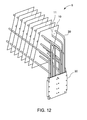
FIG. 12 is an isometric view of a heat sink including perforations in accordance with an embodiment of the inventive concept. - As used herein, the singular form of "a", "an", and "the" include plural references unless the context clearly dictates otherwise. As used herein, the statement that two or more parts or components are "coupled" shall mean that the parts are joined or operate together either directly or indirectly, i.e., through one or more intermediate parts or components, so long as a link occurs. As used herein, "directly coupled" means that two elements are directly in contact with each other. As used herein, "fixedly coupled" or "fixed" means that two components are coupled so as to move as one while maintaining a constant orientation relative to each other. As employed herein, the term "number" shall mean one or an integer greater than one (i.e., a plurality).
- Directional phrases used herein, such as, for example and without limitation, top, bottom, left, right, upper, lower, front, back, and derivatives thereof, relate to the orientation of the elements shown in the drawings and are not limiting upon the claims unless expressly recited therein.
- As used herein, the term "heating a heat pipe" and similar terms such as "heating a condenser section of the heat pipe" shall mean that heat is provided to the heat pipe in at least an amount sufficient to maintain a working fluid included in the heat pipe in liquid form when in would otherwise freeze or, in the case that the working fluid is frozen, to thaw the working fluid. The heat may be provided directly or indirectly to the heat pipe, i.e., through one or more intermediate parts or components.
-
FIG. 1 is an isometric schematic of an exemplary embodiment of aheat sink 5 implemented according to principles of the present invention.FIGS. 2 and 3 are side view and end view schematics, respectively, of theheat sink 5 illustrated inFIG. 1 .FIG. 4 is a side view schematic of anexemplary heat pipe 20 which is adapted for use in theheat sink 5 illustrated inFIGS. 1-3 . - Referring to
FIGS. 1-3 , theheat sink 5 includes a plurality offins 10, a plurality ofheat pipes 20, and at least onecold plate 30. Theheat pipes 20 each include anevaporator section 26, abend section 24, and a condenser section 22 (seeFIG. 4 ). As shown inFIGS. 1-3 , theevaporator section 26 is arranged substantially vertically and connected to thecold plate 30. Theheat pipes 20 also include thecondenser section 22 which is inclined with respect to a horizontal plane and extends through a plurality offins 10. Theevaporator section 26 and thecondenser section 22 of eachheat pipe 20 are connected by a singlestraight bend section 24. - The
evaporator section 26 and thecondenser section 22 are each substantially straight pieces of piping. In the exemplary embodiment, theevaporator sections 26 of theheat pipes 20 extend in parallel with each other and thecondenser sections 22 of theheat pipes 20 extend in parallel with each other. Thebend section 24 includes a piece of piping having a single straight bend. As employed herein, the term "single straight bend" means a single bend with a substantially constant radius and without a substantial twist or skew. The geometry of eachheat pipe 20 has minimal complexity. - A plurality of
heat pipes 20 are thermally coupled to thecold plate 30. AlthoughFIGS. 1-3 show sixteenheat pipes 20 thermally coupled to thecold plate 30, the present invention is not limited thereto. It is contemplated that any number ofheat pipes 20 greater than two can be thermally coupled to thecold plate 30 while remaining within the scope of the invention. - The
vertical evaporator sections 26 ofadjacent heat pipes 20 have different lengths. As such, thecondenser sections 22 ofadjacent heat pipes 20 are spaced apart from each other and extend through different areas of thefins 10. As illustrated inFIG. 1 , theheat pipes 20 are spread across the area of thefins 10. Spreading out the locations where theheat pipes 20 extend through thefins 10 increases the efficiency of thefins 10 in dissipating the heat of theheat pipes 20 as compared to a configuration wherein theheat pipes 20 extend through the same area of thefins 10. - The
condenser section 22 of theheat pipe 20 is inclined with respect to a horizontal plane by an angle 27 (seeFIG. 4 ). For example and without limitation, theangle 27 may be within a range of about 5-40 degrees, or preferably about 5-20 degrees. - As illustrated in
FIGS. 1-3 , theevaporator section 26 of theheat pipes 20 and thecold plate 30 are arranged substantially vertically. However, it will be appreciated that thecondenser section 22 of theheat pipes 20 and thecold plate 30 may also be tilted with respect to a vertical axis. - As illustrated in
FIGS. 1-3 , theheat pipes 20 are inserted into an upper surface of thecold plate 30. However, it is contemplated that theheat pipes 20 may be connected to thecold plate 30 in any suitable manner which thermally couples them while remaining within the scope of the invention. In an embodiment, thecold plate 30 may include an interior chamber (e.g. a vapor chamber) and theheat pipes 20 may be coupled to an upper surface of thecold plate 30 and be fluidly connected with the interior chamber of thecold plate 30. Additionally, it is contemplated that theheat pipes 20 may be attached to thecold plate 30 by, for example and without limitation, welding, soldering, or by using a suitable thermally conductive adhesive. - The
fins 10 are spaced apart from each other. The number, spacing, size, and/or thickness of thefins 10 can be varied. For example, the number, spacing, size, and/or thickness of thefins 10 can be optimized based on an expected thermal loading of different areas of thefins 10. - The
cold plate 30 is adapted to thermally couple with a heat source (seeFIG. 7 ). Thecold plate 30 may be thermally coupled with the heat source in any suitable manner such as, without limitation, by a thermally conductive adhesive. -
FIG. 4 is a side view schematic of anexemplary heat pipe 20 according to principles of the present invention. Theheat pipe 20 shown inFIG. 4 is readily adapted for use in theheat sinks 5 shown inFIGS. 1-3 . For example, theheat pipes 20 shown inFIGS. 1-3 are similar except that lengths of theevaporator sections 26 of theheat pipes 20 are varied. When employed for use in theheat sinks 5 shown inFIGS. 1-3 , theevaporator sections 26 of theheat pipes 20 are coupled with thecold plate 30. For example, theevaporator sections 26 of theheat pipes 20 can be inserted into thecold plate 30. - The
heat pipe 20 operates to transfer heat from theevaporator section 26 to thecondenser section 22 through the evaporation and condensation of a liquid included in theheat pipe 20. More particularly, when theevaporator section 26 of theheat pipe 20 is heated, the liquid evaporates into a vapor. The vapor moves to thecondenser section 22 where it cools and condenses. The liquid then moves back to theevaporator section 26 with the assistance of gravity. The cycle of evaporation and condensation transfers thermal energy from theevaporator section 26 to thecondenser section 22 of theheat pipe 20.Fins 10 thermally coupled to thecondenser section 22 assist to dissipate the heat from thecondenser section 22. Theheat pipes 20 may also include a wick which is formed on an interior of theheat pipe 20 to assist with moving the condensed liquid to theevaporator section 26. The wick may extend through the full length of theheat pipe 20 or through a portion of theheat pipe 20. - The
condenser section 22 is inclined with respect to horizontal by anangle 27 so as to utilize gravity to assist in returning condensed liquid to theevaporator section 26. As noted elsewhere herein, theangle 27 may be, for example and without limitation, in a range of 5-40 degrees, and preferably within a range of 5-20 degrees. -
FIGS. 5 and6 illustrate arrangements of heat sinks in accordance with embodiments of the present inventive concept. Referring first toFIG. 5 , a plurality ofheat sinks FIG. 5 ,heat sinks cold plate 30, a plurality ofheat pipes 20 attached to thecold plate 30, and a plurality offins 10 attached to a condenser section of theheat pipes 20. The heat sinks 101, 102, and 103 are similar to theheat sink 5 shown inFIGS. 1-3 . However, characteristics of theheat sinks heat sinks heat sink 102 has a higher density of fins 10 (i.e. more fins per unit of length) thermally coupled to the condenser section of theheat pipes 20 thanheat sinks heat sink 102 to dissipate a larger amount of heat thanheat sinks - Continuing to refer to
FIG. 5 , theheat sinks cold plates 30 are coplanar and adjacent to each other. The coplanar arrangement allows multiplecold plates 30 to be easily thermally coupled to a heat source (such as a number of power semiconductors). Additionally, a thermally conductive member, such as, without limitation, a metal piece or a heat pipe, can be attached across thecold plates 30 ofheat sinks heat sinks heat sinks - Referring to
FIG. 6 , a plurality ofheat sinks FIG. 6 ,heat sinks cold plate 30, a plurality ofheat pipes 20 thermally coupled with thecold plate 30, and a plurality offins 10 thermally coupled with a condenser section of theheat pipes 20.Heat sink 202 is similar toheat sinks heat sink 202 usesheat pipes 120 which have a longer condenser section thanheat pipes 20. Additionally,heat sink 202 includes a larger number offins 10 thanheat sinks heat pipes 120 with a longer condenser section and larger number offins 10 allowheat sink 202 to dissipate more heat thanheat sinks - While the embodiments illustrated in
FIGS. 5 and6 include multiple heat sinks arranged together while varying the density of fins coupled to the condenser section of the heat pipes or varying the length of the condenser section of the heat pipes and the number of fins coupled to the condenser section of the heat pipes, other characteristics of the heat sinks, such as, for example and without limitation, the number of heat pipes used in each heat sink or the size of each heat sink, the material used in the cold plate and/or fins, the working fluid(s) in the heat pipes, or the material used in the heat pipes can be varied while remaining within the scope of the invention. - Characteristics of each heat sink may be determined based on, for example and without limitation, expected thermal loading. For example, if it is anticipated that a heat source or arrangement of heat sources will provide a higher thermal load at a central area and a lower thermal load at an outer area, an arrangement of heat sinks which provides a higher heat dissipation to a central area, such as, for example, the arrangements shown in
FIGS. 5 and6 , can be used. While the embodiments ofFIGS. 5 and6 can dissipate a higher thermal load in a central area of a heat source or heat sources, heat sinks can be arranged with varying characteristics determined to dissipate various thermal loads while remaining within the scope of the invention. -
FIG. 7 illustrates a system in accordance with principles of the present invention according to one exemplary embodiment. The system includes aheat sink 5 includingheat pipes 20,cold plate 30, andfins 10 which are similar to theheat sink 5 described above with respect toFIGS. 1-3 . However, the arrangements of heat sinks in the embodiments shown inFIGS. 5-6 can also be adapted for use in the system shown inFIG. 7 . The system additionally includes anenclosure 100, ablower 110, a thermallyconductive adhesive 120, acircuit board 130, and aheat source 140. - As shown in
FIG. 7 , theevaporator section 26 of theheat pipes 20 is disposed primarily inside theenclosure 100 and thecondenser section 22 of theheat pipes 20 is disposed primarily outside theenclosure 100. With this arrangement, theheat source 140, which is in close proximity with theevaporator section 26 of theheat pipes 20, may be shielded from the outside environment. - The
blower 110 is adapted to blow air across thefins 10. Including theblower 110 increases the amount of heat dissipated by thefins 10 compared to aheat sink 5 which operates through only natural convection. In the embodiment shown inFIG. 7 , theblower 110 is disposed below thefins 10. However, it is contemplated that theblower 110 may be disposed at any suitable location to blow air over thefins 10 without departing from the scope of the invention. Furthermore, it is contemplated that theblower 110 may be omitted without departing from the scope of the invention. - In the embodiment shown in
FIG. 7 , theheat source 140 is thermally coupled to thecold plate 30 with a thermallyconductive adhesive 120. However, theheat source 140 may be coupled to thecold plate 30 in any suitable manner which thermally couples theheat source 140 and thecold plate 30 while remaining within the scope of the invention. - The
heat source 140 may be any type of device that generates heat, such as, without limitation, semiconductor devices which generate a large amount of heat. - In one exemplary embodiment, the
heat source 140 is a power semiconductor such as an insulated gate bipolar transistor (IGBT). However, it will be appreciated that theheat source 140 may be a variety of different semiconductor devices or other devices which generate heat. -
FIGS. 8A and 8B are side views ofheat sinks heat sink 6a illustrated inFIG. 8A includesfins 10,heat pipes 20, and acold plate 30 arranged similar to theheat sink 5 described above with respect toFIG. 1 . However, in the exemplary embodiment illustrated inFIG. 8A , the heat sink 6 further includes aheating unit 40. - The
heating unit 40 includes acontrol unit 41 which is electrically connected to a firstresistive element 42a. The firstresistive element 42a is wrapped around the condenser section of the one of theheat pipes 20. Thecontrol unit 41 applies power to the firstresistive element 42a so as to heat the firstresistive element 42a, thus heating the condenser section of theheat pipe 20 that the firstresistive element 42a is wrapped around. WhileFIG. 8A illustrates oneresistive element 42a wrapped around the condenser section of one of theheat pipes 20, theheat sink 6b illustrated inFIG. 8B includes multipleresistive elements control unit 41. The multipleresistive elements multiple heat pipes 20. It will be understood that any suitable number of resistive elements can be employed without departing from the scope of the disclosed concept. Additionally, when multiple resistive elements are used, thecontrol unit 41 may further selectively apply power to a subset of the resistive elements so as to control the number ofheat pipes 20 that are heated. - By heating the condenser sections of a subset of the
heat pipes 20, theheating unit 40 can prevent the liquid used in the subset ofheat pipes 20 from freezing in the condenser section, thus allowing the subset ofheat pipes 20 to remain operable. Alternatively, theheating unit 40 can melt liquid that is already frozen in the condenser section. Additionally, theheating unit 40 can prevent a heat source coupled to the heat sink 6 from being exposed to too wide a range of temperatures (e.g. when the liquid in theheat pipes 20 is much colder than the temperature of the heat source). Furthermore, theheating unit 40 allows liquids which have a narrower range of operation (e.g. liquids which freeze at a higher temperature) to be used in theheat pipes 20. -
FIGS. 9A and 9B are side views ofheat sinks heat sink 7a illustrated inFIG. 9A includesfins 10,heat pipes 20, and acold plate 30 arranged similar to theheat sink 5 described above with respect toFIG. 1 . However, in the exemplary embodiment illustrated inFIG. 9A , theheat sink 7a further includes aheating unit 50. - The
heating unit 50 includes acontrol unit 51 which is electrically connected to one ormore heaters 52a. Theheaters 52a are each attached to one of thefins 10 nearby arespective heat pipe 20a. Thecontrol unit 51 applies power to selectedheaters 52a so as to heat the selectedheat pipe 20a. WhileFIG. 9A illustrates a plurality of heaters 52 disposed on thefins 10 in the vicinity of one of theheat pipes 20a, it will be understood that multiple sets of heaters may be used to heat multiple different heat pipes. For example, as illustrated inFIG. 9B , theheating unit 50 includes a first set ofheaters 52a disposed nearby afirst heat pipe 20a, a second set ofheaters 52b disposed nearby asecond heat pipe 52b, and a third set ofheaters 52c disposed nearby athird heat pipe 20c. Thecontrol unit 41 may further selectively apply power to a subset of theheaters heaters 52a are closer to therespective heat pipe 20a than any other heat pipe. Each of theheaters 52a may also be located within a range of about 1-4 cm of therespective heat pipe 20a. However, the distance of theheaters 52a from therespective heat pipe 20a can be suitably changed based on, for example, changes in the scale of the heat sink. -
FIG. 10 is a side view of aheat sink 8 implemented according to a further exemplary embodiment of the present invention. Theheat sink 8 illustrated inFIG. 10 includesfins 10,heat pipes 20, and acold plate 30 arranged similar to theheat sink 5 described above with respect toFIG. 1 . However, in the exemplary embodiment illustrated inFIG. 10 , the heat sink 6 further includes aheating unit 60. - The
heating unit 60 includes acontrol unit 61 which is electrically connected toradiant heaters 62. Thecontrol unit 61 applies power to theradiant heaters 62, thus causing theradiant heaters 62 to emit radiant energy. In addition, in the present embodiment, the condenser sections of a selected subset of theheat pipes 20 are colored with a dark color which is effective in absorbing radiant energy. The selected subset ofheat pipes 20 absorbs radiant energy emitted from theradiant heaters 62, and are thus heated. Whileother heat pipes 20 also absorb radiant energy, theheat pipes 20 which are colored with the dark color are more effective at absorbing radiant energy, and thus theradiant heaters 62 do not require as much power to heat theheat pipes 20 colored with the dark color. - In the embodiment illustrated in
FIG. 10 ,radiant heaters 62 are disposed above and below thefins 10. However, it will be understood that other suitable arrangements of radiant heaters are within the scope of the invention. For example, one or moreradiant heaters 62 may be disposed only above or only below thefins 10. -
FIG. 11 is a side view of a heat sink implemented according to a further exemplary embodiment of the present invention. Theheat sink 9 illustrated inFIG. 11 includesfins 10,heat pipes 20, and acold plate 30 arranged similar to theheat sink 5 described above with respect toFIG. 1 . However, in the exemplary embodiment illustrated inFIG. 11 , theheat sink 9 further includes aheating unit 70. - The
heating unit 70 includes acontrol unit 71 which is electrically connected to atubular heater 72. Thetubular heater 72 can extend through thefins 10 similar to thecondenser sections 22 of the plurality ofheat pipes 20. Thecontrol unit 61 applies power to thetubular heater 72, thus causing thetubular heater 72 to heatnearby heat pipes 20. In an exemplary embodiment, thetubular heater 72 is constructed from a hollow pipe with a heating element disposed therein. - In some embodiments, the
control units radiant heaters 62, ortubular heater 72 based on at least one of a temperature of a heat source coupled to thecold plate 30, a temperature of the condenser sections of the plurality ofheat pipes 20, and an ambient temperature. Additionally, thecontrol units radiant heaters 62, ortubular heater 72 based on, for example, temperature data received from an external source (e.g., a temperature sensor located elsewhere in the apparatus, a weather station, etc.). Thecontrol units radiant heaters 62, ortubular heater 72 based on any of a temperature of thefins 10, an air temperature at the top or bottom of thefins 10, and a temperature at the adiabatic section of theheat pipes 20. Thecontrol units - The
control units radiant heaters 62, ortubular heater 72 in any suitable manner. For example,control units radiant heaters 62, ortubular heater 72 to apply power to, but how much power to apply and how long to apply the power. Additionally, controlsunits radiant heaters 62, ortubular heater 72. - The
fins 10 may also be structured such that the fins do not dissipate heat from a selected subset of heat pipes. For example and without limitation, thefins 10 can be structured so that they are not thermally coupled with a selected subset ofheat pipes 20. Referring toFIG. 12 , thefins 10 may includeperforations 11 structured such that thefins 10 do not effectively dissipate heat from a selected subset ofheat pipes 20. In the example shown inFIG. 12 , theperforations 11 prevent thefins 10 from effectively dissipating the heat from one of theheat pipes 20. However, theperforations 11 can be structured to prevent thefins 10 from effectively dissipating the heat ofmultiple heat pipes 20 without departing from the scope of the disclosed concept. When thefins 10 do not effectively dissipate heat from a selected subset ofheat pipes 20, the selected subset ofheat pipes 20 will operate at a higher temperature, and thus will not freeze as quickly asother heat pipes 20. As such, the heat sink can remain operational at a lower temperature. The same effect can be accomplished by installing separate fins or fin stacks rather than perforating thefins 10. - It is appreciated that the
heat sinks FIGS. 8 ,9 ,10, and 11 , can be readily adapted for use in the system illustrated inFIG. 7 or adapted for use in theheat sink 1 illustrated inFIG. 1 . It is also appreciated that features of the above-described embodiments may be used in combination with each other. For example and without limitation, it is contemplated that a heat sink may incorporate both theheating unit 50 illustrated inFIG. 9 and theheating unit 60 illustrated inFIG. 10 , or any other combination of features. - In the claims, any reference signs placed between parentheses shall not be construed as limiting the claim. The word "comprising" or "including" does not exclude the presence of elements or steps other than those listed in a claim. In a device claim enumerating several means, several of these means may be embodied by one and the same item of hardware. The word "a" or "an" preceding an element does not exclude the presence of a plurality of such elements. In any device claim enumerating several means, several of these means may be embodied by one and the same item of hardware. The mere fact that certain elements are recited in mutually different dependent claims does not indicate that these elements cannot be used in combination.
- Although the invention has been described in detail for the purpose of illustration based on what is currently considered to be the most practical and preferred embodiments, it is to be understood that such detail is solely for that purpose and that the invention is not limited to the disclosed embodiments, but, on the contrary, is intended to cover modifications and equivalent arrangements that are within the spirit and scope of the appended claims. For example, it is to be understood that the present invention contemplates that, to the extent possible, one or more features of any embodiment can be combined with one or more features of any other embodiment.
Claims (15)
- A heat sink (6a; 6b; 7a; 7b; 8; 9), comprising:a cold plate (30) having a first surface adapted to thermally couple to a heat source;a plurality of heat pipes (20), each of the heat pipes having an evaporator section (26) thermally coupled to the cold plate (30) and a condenser section (22) coupled to the evaporator section (26);a plurality of fins (10) thermally coupled to the condenser sections (22) of the plurality of heat pipes (20); anda heating unit (40; 50; 60; 70) adapted to heat condenser sections (22) of only a subset of the plurality of heat pipes (20).
- A heat sink (6a; 6b; 7a; 7b; 8; 9) according to claim 1, wherein the heating unit (40; 50; 60; 70) comprises:a control unit (41; 51; 61; 71) adapted to selectively provide power to heat the subset of the plurality of heat pipes (20).
- A heat sink (6a; 6b) according to claim 2, wherein the heating unit (40) comprises:one or more resistive elements (42a-42c) disposed around the condenser sections (22) of the subset of the plurality of heat pipes (20),wherein the control unit (41) selectively provides power to the one or more resistive elements (42a-42c) so as to heat the one or more resistive elements (42a-42c).
- A heat sink (6a; 6b) according to claim 3, wherein each of the one or more resistive elements (42a-42c) is each wrapped around a respective one of the heat pipes (20) of the subset of the plurality of heat pipes (20).
- A heat sink (7a; 7b) according to claim 2, wherein the heating unit (50) comprises:a plurality of heating devices (52a) electrically connected to the control unit (51),wherein each of the plurality of heating devices (52a) is attached to a respective one of the fins (10) nearby one of the heat pipes (20a) of the subset of the plurality of heat pipes (20), and wherein the control unit (51) selectively provides power to the heating devices (52a) to heat the heating devices (52a).
- A heat sink (7a; 7b) according to claim 5, wherein the heating unit (50) further comprises:a plurality of second heating devices (52b), wherein each of the plurality of second heating devices (52b) is attached to a respective one of the fins (10) nearby a second one of the heat pipes (20b) of the subset of the plurality of heat pipes (20).
- A heat sink (8) according to claim 2, wherein the heating unit (60) comprises:one or more radiant heaters (62) electrically connected to the control unit (61) and adapted to apply radiant energy to the condenser sections (22) of the plurality of heat pipes (20),wherein the condenser sections (22) of the subset of heat pipes (20) are provided with a means of increasing absorption of radiant energy.
- A heat sink (8) according to claim 7, wherein the means of increasing absorption of radiant energy is dark coloring of the subset of heat pipes (20).
- A heat sink (8) according to claim 7 or claim 8, wherein the one or more radiant heaters (62) are disposed on opposite sides of the fins (10).
- A heat sink (9) according to claim 2, wherein the heating unit (70) comprises:one or more tubular heaters (72) each extending through the plurality of fins (10).
- A heat sink (9) according to claim 10, wherein each tubular heater (72) comprises:a hollow pipe extending through the plurality of fins (10); anda heating element disposed inside the hollow pipe.
- A heat sink (6a; 6b; 7a; 7b; 8; 9) according to any of claims 2 to 11, further comprising:at least one temperature sensor adapted to sense at least one of a temperature of the heat source, a temperature of the condenser sections (22) of the plurality of heat pipes (20), and an ambient temperature, wherein the control unit (41; 51; 61; 71) controls the heating unit (40; 50; 60; 70) to heat the subset of the plurality of heat pipes (20) based on at least one of the temperature of the heat source, the temperature of the condenser sections of the plurality of heat pipes, and the ambient temperature.
- A heat sink (6a; 6b; 7a; 7b; 8; 9) according to any of claims 2 to 12,
wherein the control unit (41; 51; 61; 71) determines an amount of heat to apply to the subset of the plurality of heat pipes (20) and controls the amount of heat by controlling at least one of a number of heat pipes heat is applied to, a duration in which power is applied, and an amount of power which is applied. - A heat sink (6a; 6b; 7a; 7b; 8; 9) according to any preceding claim,
wherein the plurality of fins (10) each include at least one perforation (11) which reduces an amount the plurality of fins dissipates heat of a selected one or more of the heat pipes of the plurality of heat pipes (20) with respect to the remaining heat pipes of the plurality of heat pipes (20). - A method of heating heat pipes (20), the method comprising:providing a cold plate (30) having a first surface adapted to thermally couple to a heat source;providing a plurality of heat pipes (20), each of the heat pipes having an evaporator section (26) thermally coupled to the cold plate (30) and a condenser section (22) coupled to the evaporator section (26);providing a plurality of fins (10) thermally coupled to the condenser sections (22) of the plurality of heat pipes (20); andheating condenser sections (22) of only a subset of the plurality of heat pipes (20).
Applications Claiming Priority (2)
| Application Number | Priority Date | Filing Date | Title |
|---|---|---|---|
| US201361805198P | 2013-03-26 | 2013-03-26 | |
| US14/200,824 US20140290929A1 (en) | 2013-03-26 | 2014-03-07 | Heat pipe heat sink with heating unit |
Publications (3)
| Publication Number | Publication Date |
|---|---|
| EP2784811A2 true EP2784811A2 (en) | 2014-10-01 |
| EP2784811A3 EP2784811A3 (en) | 2015-05-27 |
| EP2784811B1 EP2784811B1 (en) | 2017-09-20 |
Family
ID=50382293
Family Applications (1)
| Application Number | Title | Priority Date | Filing Date |
|---|---|---|---|
| EP14161555.9A Not-in-force EP2784811B1 (en) | 2013-03-26 | 2014-03-25 | Heat pipe sink with heating unit |
Country Status (3)
| Country | Link |
|---|---|
| US (1) | US20140290929A1 (en) |
| EP (1) | EP2784811B1 (en) |
| CN (1) | CN104142077A (en) |
Families Citing this family (14)
| Publication number | Priority date | Publication date | Assignee | Title |
|---|---|---|---|---|
| US10126356B2 (en) * | 2009-11-30 | 2018-11-13 | Essai, Inc. | Systems and methods for conforming test tooling to integrated circuit device with whirlwind cold plate |
| CN103167780B (en) * | 2011-12-16 | 2016-06-08 | 台达电子企业管理(上海)有限公司 | Power model combined radiator assembly |
| EP2869443B1 (en) * | 2012-06-29 | 2017-03-01 | Toshiba Mitsubishi-Electric Industrial Systems Corporation | Power converter |
| EP3027993A1 (en) * | 2013-07-29 | 2016-06-08 | GE Intelligent Platforms, Inc. | Heatspreader with extended surface for heat transfer through a sealed chassis wall |
| CN104613804B (en) * | 2014-12-15 | 2017-03-01 | 青岛海尔股份有限公司 | Bending pipe fitting and the semiconductor freezer with this bending pipe fitting |
| WO2016110977A1 (en) * | 2015-01-08 | 2016-07-14 | 三菱電機株式会社 | Cooling device for railway vehicle |
| KR20160139094A (en) * | 2015-05-26 | 2016-12-07 | 엘에스산전 주식회사 | Closed cabinet for electric device having heat pipe |
| CN105520800B (en) * | 2015-12-21 | 2018-08-24 | 丁平 | A kind of waist rehabilitation utensil and automotive seat with the utensil and bed and sofa |
| CN107156602A (en) * | 2017-07-10 | 2017-09-15 | 合肥美菱股份有限公司 | A kind of defrosting plate |
| CN111788876B (en) * | 2017-12-08 | 2023-07-07 | 株式会社Kmw | Heat sink for electronic element |
| JP6640401B1 (en) * | 2019-04-18 | 2020-02-05 | 古河電気工業株式会社 | heatsink |
| CN110726317B (en) * | 2019-09-05 | 2020-10-30 | 浙江大学 | Ultrasonic pulsating heat pipe radiator with thermoelectric power generation driving and temperature early warning functions |
| US11051428B2 (en) * | 2019-10-31 | 2021-06-29 | Hamilton Sunstrand Corporation | Oscillating heat pipe integrated thermal management system for power electronics |
| CN115479426B (en) * | 2021-06-16 | 2024-01-05 | 青岛海尔电冰箱有限公司 | Refrigerator and food material processing device thereof |
Family Cites Families (11)
| Publication number | Priority date | Publication date | Assignee | Title |
|---|---|---|---|---|
| US3934643A (en) * | 1971-07-26 | 1976-01-27 | Nikolaus Laing | Controllable heat pipe |
| JPS5623764A (en) * | 1979-08-01 | 1981-03-06 | Hitachi Ltd | Enclosed boiling type cooler |
| JPS591994A (en) * | 1982-06-25 | 1984-01-07 | Toshiba Corp | Heat pipe for temperature control |
| JPS60185038A (en) * | 1984-03-03 | 1985-09-20 | Matsushita Electric Works Ltd | Heat exchanging and ventilating fan device |
| US5159972A (en) * | 1991-03-21 | 1992-11-03 | Florida Power Corporation | Controllable heat pipes for thermal energy transfer |
| JP3067399B2 (en) * | 1992-07-03 | 2000-07-17 | 株式会社日立製作所 | Semiconductor cooling device |
| JPH06276742A (en) * | 1993-03-17 | 1994-09-30 | Toshiba Corp | Power converter |
| JP2996843B2 (en) * | 1993-09-14 | 2000-01-11 | 株式会社東芝 | Heat pipe cooler |
| WO2000057471A1 (en) * | 1999-03-19 | 2000-09-28 | Hitachi, Ltd. | Heat pipe cooling device and power converting device |
| US6959757B2 (en) * | 2001-08-10 | 2005-11-01 | Carrier Corporation | Black layer coated heat exchanger |
| JP5125889B2 (en) * | 2008-08-28 | 2013-01-23 | 三菱電機株式会社 | Variable conductance heat pipe |
-
2014
- 2014-03-07 US US14/200,824 patent/US20140290929A1/en not_active Abandoned
- 2014-03-25 EP EP14161555.9A patent/EP2784811B1/en not_active Not-in-force
- 2014-03-26 CN CN201410114334.1A patent/CN104142077A/en active Pending
Non-Patent Citations (1)
| Title |
|---|
| None |
Also Published As
| Publication number | Publication date |
|---|---|
| CN104142077A (en) | 2014-11-12 |
| EP2784811B1 (en) | 2017-09-20 |
| EP2784811A3 (en) | 2015-05-27 |
| US20140290929A1 (en) | 2014-10-02 |
Similar Documents
| Publication | Publication Date | Title |
|---|---|---|
| EP2784811B1 (en) | Heat pipe sink with heating unit | |
| EP2784812A2 (en) | Heat pipe sink for high power density | |
| US20180187978A1 (en) | Fin-diffuser heat sink with high conductivity heat spreader | |
| US6845622B2 (en) | Phase-change refrigeration apparatus with thermoelectric cooling element and methods | |
| CN102128518B (en) | TEC (Thermoelectric Cooling Module) refrigerating device and electrical device using same | |
| CN101287350B (en) | heat sink | |
| US7304842B2 (en) | Apparatuses and methods for cooling electronic devices in computer systems | |
| US8773855B2 (en) | Heat-dissipating device and electric apparatus having the same | |
| US20040244950A1 (en) | Optimized multiple heat pipe blocks for electronics cooling | |
| US20150000871A1 (en) | Housing with heat pipes integrated into enclosure fins | |
| US8505613B2 (en) | Die having a via filled with a heat-dissipating material | |
| CN101573790A (en) | Three-Dimensional Heat Dissipation in Air-Cooled Thermal Devices | |
| US20040163796A1 (en) | Circulative cooling apparatus | |
| JP5756236B2 (en) | Heat pump device and temperature control device using electric calorie effect | |
| US20100032141A1 (en) | cooling system utilizing carbon nanotubes for cooling of electrical systems | |
| JP5874935B2 (en) | Flat plate cooling device and method of using the same | |
| US10881034B2 (en) | Passive nano-heat pipes for cooling and thermal management of electronics and power conversion devices | |
| JP4279282B2 (en) | Cooling device for electronic equipment | |
| JP5624771B2 (en) | Heat pipe and heat sink with heat pipe | |
| GB2520108A (en) | Fin-diffuser heat sink with high conductivity heat spreader | |
| KR20150066398A (en) | Heat radiater for cup holder and cup holder using the same | |
| KR102170314B1 (en) | Heat dissipation device of power semiconductor module | |
| CN100470774C (en) | heat sink | |
| JP2020016425A (en) | Heat sink and cooling device | |
| US20160334168A1 (en) | Cooling device and electronic device provided with cooling device |
Legal Events
| Date | Code | Title | Description |
|---|---|---|---|
| 17P | Request for examination filed |
Effective date: 20140325 |
|
| AK | Designated contracting states |
Kind code of ref document: A2 Designated state(s): AL AT BE BG CH CY CZ DE DK EE ES FI FR GB GR HR HU IE IS IT LI LT LU LV MC MK MT NL NO PL PT RO RS SE SI SK SM TR |
|
| AX | Request for extension of the european patent |
Extension state: BA ME |
|
| PUAI | Public reference made under article 153(3) epc to a published international application that has entered the european phase |
Free format text: ORIGINAL CODE: 0009012 |
|
| PUAL | Search report despatched |
Free format text: ORIGINAL CODE: 0009013 |
|
| AK | Designated contracting states |
Kind code of ref document: A3 Designated state(s): AL AT BE BG CH CY CZ DE DK EE ES FI FR GB GR HR HU IE IS IT LI LT LU LV MC MK MT NL NO PL PT RO RS SE SI SK SM TR |
|
| AX | Request for extension of the european patent |
Extension state: BA ME |
|
| RIC1 | Information provided on ipc code assigned before grant |
Ipc: F28D 15/02 20060101ALI20150422BHEP Ipc: H01L 23/427 20060101AFI20150422BHEP |
|
| R17P | Request for examination filed (corrected) |
Effective date: 20151125 |
|
| RBV | Designated contracting states (corrected) |
Designated state(s): AL AT BE BG CH CY CZ DE DK EE ES FI FR GB GR HR HU IE IS IT LI LT LU LV MC MK MT NL NO PL PT RO RS SE SI SK SM TR |
|
| 17Q | First examination report despatched |
Effective date: 20160414 |
|
| REG | Reference to a national code |
Ref country code: DE Ref legal event code: R079 Ref document number: 602014014725 Country of ref document: DE Free format text: PREVIOUS MAIN CLASS: H01L0023340000 Ipc: H01L0023427000 |
|
| GRAP | Despatch of communication of intention to grant a patent |
Free format text: ORIGINAL CODE: EPIDOSNIGR1 |
|
| INTG | Intention to grant announced |
Effective date: 20170331 |
|
| RIC1 | Information provided on ipc code assigned before grant |
Ipc: H01L 23/34 20060101ALI20170322BHEP Ipc: F28D 15/02 20060101ALI20170322BHEP Ipc: H01L 23/427 20060101AFI20170322BHEP |
|
| GRAS | Grant fee paid |
Free format text: ORIGINAL CODE: EPIDOSNIGR3 |
|
| GRAA | (expected) grant |
Free format text: ORIGINAL CODE: 0009210 |
|
| AK | Designated contracting states |
Kind code of ref document: B1 Designated state(s): AL AT BE BG CH CY CZ DE DK EE ES FI FR GB GR HR HU IE IS IT LI LT LU LV MC MK MT NL NO PL PT RO RS SE SI SK SM TR |
|
| REG | Reference to a national code |
Ref country code: GB Ref legal event code: FG4D |
|
| REG | Reference to a national code |
Ref country code: CH Ref legal event code: EP |
|
| REG | Reference to a national code |
Ref country code: AT Ref legal event code: REF Ref document number: 930785 Country of ref document: AT Kind code of ref document: T Effective date: 20171015 |
|
| REG | Reference to a national code |
Ref country code: IE Ref legal event code: FG4D |
|
| REG | Reference to a national code |
Ref country code: DE Ref legal event code: R096 Ref document number: 602014014725 Country of ref document: DE |
|
| REG | Reference to a national code |
Ref country code: NL Ref legal event code: MP Effective date: 20170920 |
|
| PG25 | Lapsed in a contracting state [announced via postgrant information from national office to epo] |
Ref country code: NO Free format text: LAPSE BECAUSE OF FAILURE TO SUBMIT A TRANSLATION OF THE DESCRIPTION OR TO PAY THE FEE WITHIN THE PRESCRIBED TIME-LIMIT Effective date: 20171220 Ref country code: FI Free format text: LAPSE BECAUSE OF FAILURE TO SUBMIT A TRANSLATION OF THE DESCRIPTION OR TO PAY THE FEE WITHIN THE PRESCRIBED TIME-LIMIT Effective date: 20170920 Ref country code: HR Free format text: LAPSE BECAUSE OF FAILURE TO SUBMIT A TRANSLATION OF THE DESCRIPTION OR TO PAY THE FEE WITHIN THE PRESCRIBED TIME-LIMIT Effective date: 20170920 Ref country code: LT Free format text: LAPSE BECAUSE OF FAILURE TO SUBMIT A TRANSLATION OF THE DESCRIPTION OR TO PAY THE FEE WITHIN THE PRESCRIBED TIME-LIMIT Effective date: 20170920 Ref country code: SE Free format text: LAPSE BECAUSE OF FAILURE TO SUBMIT A TRANSLATION OF THE DESCRIPTION OR TO PAY THE FEE WITHIN THE PRESCRIBED TIME-LIMIT Effective date: 20170920 |
|
| REG | Reference to a national code |
Ref country code: LT Ref legal event code: MG4D |
|
| REG | Reference to a national code |
Ref country code: AT Ref legal event code: MK05 Ref document number: 930785 Country of ref document: AT Kind code of ref document: T Effective date: 20170920 |
|
| PG25 | Lapsed in a contracting state [announced via postgrant information from national office to epo] |
Ref country code: LV Free format text: LAPSE BECAUSE OF FAILURE TO SUBMIT A TRANSLATION OF THE DESCRIPTION OR TO PAY THE FEE WITHIN THE PRESCRIBED TIME-LIMIT Effective date: 20170920 Ref country code: GR Free format text: LAPSE BECAUSE OF FAILURE TO SUBMIT A TRANSLATION OF THE DESCRIPTION OR TO PAY THE FEE WITHIN THE PRESCRIBED TIME-LIMIT Effective date: 20171221 Ref country code: BG Free format text: LAPSE BECAUSE OF FAILURE TO SUBMIT A TRANSLATION OF THE DESCRIPTION OR TO PAY THE FEE WITHIN THE PRESCRIBED TIME-LIMIT Effective date: 20171220 Ref country code: RS Free format text: LAPSE BECAUSE OF FAILURE TO SUBMIT A TRANSLATION OF THE DESCRIPTION OR TO PAY THE FEE WITHIN THE PRESCRIBED TIME-LIMIT Effective date: 20170920 |
|
| REG | Reference to a national code |
Ref country code: FR Ref legal event code: PLFP Year of fee payment: 5 |
|
| PG25 | Lapsed in a contracting state [announced via postgrant information from national office to epo] |
Ref country code: NL Free format text: LAPSE BECAUSE OF FAILURE TO SUBMIT A TRANSLATION OF THE DESCRIPTION OR TO PAY THE FEE WITHIN THE PRESCRIBED TIME-LIMIT Effective date: 20170920 |
|
| PG25 | Lapsed in a contracting state [announced via postgrant information from national office to epo] |
Ref country code: RO Free format text: LAPSE BECAUSE OF FAILURE TO SUBMIT A TRANSLATION OF THE DESCRIPTION OR TO PAY THE FEE WITHIN THE PRESCRIBED TIME-LIMIT Effective date: 20170920 Ref country code: PL Free format text: LAPSE BECAUSE OF FAILURE TO SUBMIT A TRANSLATION OF THE DESCRIPTION OR TO PAY THE FEE WITHIN THE PRESCRIBED TIME-LIMIT Effective date: 20170920 Ref country code: ES Free format text: LAPSE BECAUSE OF FAILURE TO SUBMIT A TRANSLATION OF THE DESCRIPTION OR TO PAY THE FEE WITHIN THE PRESCRIBED TIME-LIMIT Effective date: 20170920 Ref country code: CZ Free format text: LAPSE BECAUSE OF FAILURE TO SUBMIT A TRANSLATION OF THE DESCRIPTION OR TO PAY THE FEE WITHIN THE PRESCRIBED TIME-LIMIT Effective date: 20170920 |
|
| PG25 | Lapsed in a contracting state [announced via postgrant information from national office to epo] |
Ref country code: SK Free format text: LAPSE BECAUSE OF FAILURE TO SUBMIT A TRANSLATION OF THE DESCRIPTION OR TO PAY THE FEE WITHIN THE PRESCRIBED TIME-LIMIT Effective date: 20170920 Ref country code: SM Free format text: LAPSE BECAUSE OF FAILURE TO SUBMIT A TRANSLATION OF THE DESCRIPTION OR TO PAY THE FEE WITHIN THE PRESCRIBED TIME-LIMIT Effective date: 20170920 Ref country code: IT Free format text: LAPSE BECAUSE OF FAILURE TO SUBMIT A TRANSLATION OF THE DESCRIPTION OR TO PAY THE FEE WITHIN THE PRESCRIBED TIME-LIMIT Effective date: 20170920 Ref country code: IS Free format text: LAPSE BECAUSE OF FAILURE TO SUBMIT A TRANSLATION OF THE DESCRIPTION OR TO PAY THE FEE WITHIN THE PRESCRIBED TIME-LIMIT Effective date: 20180120 Ref country code: EE Free format text: LAPSE BECAUSE OF FAILURE TO SUBMIT A TRANSLATION OF THE DESCRIPTION OR TO PAY THE FEE WITHIN THE PRESCRIBED TIME-LIMIT Effective date: 20170920 Ref country code: AT Free format text: LAPSE BECAUSE OF FAILURE TO SUBMIT A TRANSLATION OF THE DESCRIPTION OR TO PAY THE FEE WITHIN THE PRESCRIBED TIME-LIMIT Effective date: 20170920 |
|
| REG | Reference to a national code |
Ref country code: DE Ref legal event code: R097 Ref document number: 602014014725 Country of ref document: DE |
|
| PLBE | No opposition filed within time limit |
Free format text: ORIGINAL CODE: 0009261 |
|
| STAA | Information on the status of an ep patent application or granted ep patent |
Free format text: STATUS: NO OPPOSITION FILED WITHIN TIME LIMIT |
|
| PG25 | Lapsed in a contracting state [announced via postgrant information from national office to epo] |
Ref country code: DK Free format text: LAPSE BECAUSE OF FAILURE TO SUBMIT A TRANSLATION OF THE DESCRIPTION OR TO PAY THE FEE WITHIN THE PRESCRIBED TIME-LIMIT Effective date: 20170920 |
|
| 26N | No opposition filed |
Effective date: 20180621 |
|
| REG | Reference to a national code |
Ref country code: CH Ref legal event code: PL |
|
| PG25 | Lapsed in a contracting state [announced via postgrant information from national office to epo] |
Ref country code: MC Free format text: LAPSE BECAUSE OF FAILURE TO SUBMIT A TRANSLATION OF THE DESCRIPTION OR TO PAY THE FEE WITHIN THE PRESCRIBED TIME-LIMIT Effective date: 20170920 Ref country code: SI Free format text: LAPSE BECAUSE OF FAILURE TO SUBMIT A TRANSLATION OF THE DESCRIPTION OR TO PAY THE FEE WITHIN THE PRESCRIBED TIME-LIMIT Effective date: 20170920 |
|
| REG | Reference to a national code |
Ref country code: BE Ref legal event code: MM Effective date: 20180331 |
|
| REG | Reference to a national code |
Ref country code: IE Ref legal event code: MM4A |
|
| PG25 | Lapsed in a contracting state [announced via postgrant information from national office to epo] |
Ref country code: LU Free format text: LAPSE BECAUSE OF NON-PAYMENT OF DUE FEES Effective date: 20180325 |
|
| PG25 | Lapsed in a contracting state [announced via postgrant information from national office to epo] |
Ref country code: IE Free format text: LAPSE BECAUSE OF NON-PAYMENT OF DUE FEES Effective date: 20180325 |
|
| PG25 | Lapsed in a contracting state [announced via postgrant information from national office to epo] |
Ref country code: LI Free format text: LAPSE BECAUSE OF NON-PAYMENT OF DUE FEES Effective date: 20180331 Ref country code: BE Free format text: LAPSE BECAUSE OF NON-PAYMENT OF DUE FEES Effective date: 20180331 Ref country code: CH Free format text: LAPSE BECAUSE OF NON-PAYMENT OF DUE FEES Effective date: 20180331 |
|
| PGFP | Annual fee paid to national office [announced via postgrant information from national office to epo] |
Ref country code: GB Payment date: 20190222 Year of fee payment: 6 Ref country code: DE Payment date: 20190219 Year of fee payment: 6 |
|
| PGFP | Annual fee paid to national office [announced via postgrant information from national office to epo] |
Ref country code: FR Payment date: 20190220 Year of fee payment: 6 |
|
| PG25 | Lapsed in a contracting state [announced via postgrant information from national office to epo] |
Ref country code: MT Free format text: LAPSE BECAUSE OF NON-PAYMENT OF DUE FEES Effective date: 20180325 |
|
| PG25 | Lapsed in a contracting state [announced via postgrant information from national office to epo] |
Ref country code: TR Free format text: LAPSE BECAUSE OF FAILURE TO SUBMIT A TRANSLATION OF THE DESCRIPTION OR TO PAY THE FEE WITHIN THE PRESCRIBED TIME-LIMIT Effective date: 20170920 |
|
| PG25 | Lapsed in a contracting state [announced via postgrant information from national office to epo] |
Ref country code: PT Free format text: LAPSE BECAUSE OF FAILURE TO SUBMIT A TRANSLATION OF THE DESCRIPTION OR TO PAY THE FEE WITHIN THE PRESCRIBED TIME-LIMIT Effective date: 20170920 Ref country code: HU Free format text: LAPSE BECAUSE OF FAILURE TO SUBMIT A TRANSLATION OF THE DESCRIPTION OR TO PAY THE FEE WITHIN THE PRESCRIBED TIME-LIMIT; INVALID AB INITIO Effective date: 20140325 |
|
| PG25 | Lapsed in a contracting state [announced via postgrant information from national office to epo] |
Ref country code: CY Free format text: LAPSE BECAUSE OF FAILURE TO SUBMIT A TRANSLATION OF THE DESCRIPTION OR TO PAY THE FEE WITHIN THE PRESCRIBED TIME-LIMIT Effective date: 20170920 Ref country code: MK Free format text: LAPSE BECAUSE OF NON-PAYMENT OF DUE FEES Effective date: 20170920 |
|
| PG25 | Lapsed in a contracting state [announced via postgrant information from national office to epo] |
Ref country code: AL Free format text: LAPSE BECAUSE OF FAILURE TO SUBMIT A TRANSLATION OF THE DESCRIPTION OR TO PAY THE FEE WITHIN THE PRESCRIBED TIME-LIMIT Effective date: 20170920 |
|
| REG | Reference to a national code |
Ref country code: DE Ref legal event code: R119 Ref document number: 602014014725 Country of ref document: DE |
|
| PG25 | Lapsed in a contracting state [announced via postgrant information from national office to epo] |
Ref country code: FR Free format text: LAPSE BECAUSE OF NON-PAYMENT OF DUE FEES Effective date: 20200331 Ref country code: DE Free format text: LAPSE BECAUSE OF NON-PAYMENT OF DUE FEES Effective date: 20201001 |
|
| GBPC | Gb: european patent ceased through non-payment of renewal fee |
Effective date: 20200325 |
|
| PG25 | Lapsed in a contracting state [announced via postgrant information from national office to epo] |
Ref country code: GB Free format text: LAPSE BECAUSE OF NON-PAYMENT OF DUE FEES Effective date: 20200325 |