EP2784582A1 - Projector device, head-up display device, and projector device control method - Google Patents
Projector device, head-up display device, and projector device control method Download PDFInfo
- Publication number
- EP2784582A1 EP2784582A1 EP20140160616 EP14160616A EP2784582A1 EP 2784582 A1 EP2784582 A1 EP 2784582A1 EP 20140160616 EP20140160616 EP 20140160616 EP 14160616 A EP14160616 A EP 14160616A EP 2784582 A1 EP2784582 A1 EP 2784582A1
- Authority
- EP
- European Patent Office
- Prior art keywords
- light source
- intensity
- unit
- image
- projector device
- Prior art date
- Legal status (The legal status is an assumption and is not a legal conclusion. Google has not performed a legal analysis and makes no representation as to the accuracy of the status listed.)
- Withdrawn
Links
- 238000000034 method Methods 0.000 title claims description 24
- 235000019646 color tone Nutrition 0.000 claims description 103
- 238000004590 computer program Methods 0.000 description 17
- 230000006870 function Effects 0.000 description 6
- 230000003247 decreasing effect Effects 0.000 description 4
- 238000010586 diagram Methods 0.000 description 4
- 230000007423 decrease Effects 0.000 description 3
- 238000004891 communication Methods 0.000 description 2
- 230000000694 effects Effects 0.000 description 2
- 238000012423 maintenance Methods 0.000 description 2
- 230000001186 cumulative effect Effects 0.000 description 1
- 230000006866 deterioration Effects 0.000 description 1
- 230000010354 integration Effects 0.000 description 1
- 239000000463 material Substances 0.000 description 1
- 230000004044 response Effects 0.000 description 1
- 239000004065 semiconductor Substances 0.000 description 1
Images




Classifications
-
- G—PHYSICS
- G02—OPTICS
- G02B—OPTICAL ELEMENTS, SYSTEMS OR APPARATUS
- G02B27/00—Optical systems or apparatus not provided for by any of the groups G02B1/00 - G02B26/00, G02B30/00
- G02B27/01—Head-up displays
- G02B27/0101—Head-up displays characterised by optical features
-
- G—PHYSICS
- G03—PHOTOGRAPHY; CINEMATOGRAPHY; ANALOGOUS TECHNIQUES USING WAVES OTHER THAN OPTICAL WAVES; ELECTROGRAPHY; HOLOGRAPHY
- G03B—APPARATUS OR ARRANGEMENTS FOR TAKING PHOTOGRAPHS OR FOR PROJECTING OR VIEWING THEM; APPARATUS OR ARRANGEMENTS EMPLOYING ANALOGOUS TECHNIQUES USING WAVES OTHER THAN OPTICAL WAVES; ACCESSORIES THEREFOR
- G03B21/00—Projectors or projection-type viewers; Accessories therefor
- G03B21/14—Details
- G03B21/20—Lamp housings
- G03B21/2006—Lamp housings characterised by the light source
- G03B21/2033—LED or laser light sources
-
- G—PHYSICS
- G03—PHOTOGRAPHY; CINEMATOGRAPHY; ANALOGOUS TECHNIQUES USING WAVES OTHER THAN OPTICAL WAVES; ELECTROGRAPHY; HOLOGRAPHY
- G03B—APPARATUS OR ARRANGEMENTS FOR TAKING PHOTOGRAPHS OR FOR PROJECTING OR VIEWING THEM; APPARATUS OR ARRANGEMENTS EMPLOYING ANALOGOUS TECHNIQUES USING WAVES OTHER THAN OPTICAL WAVES; ACCESSORIES THEREFOR
- G03B21/00—Projectors or projection-type viewers; Accessories therefor
- G03B21/14—Details
- G03B21/20—Lamp housings
- G03B21/2053—Intensity control of illuminating light
-
- H—ELECTRICITY
- H04—ELECTRIC COMMUNICATION TECHNIQUE
- H04N—PICTORIAL COMMUNICATION, e.g. TELEVISION
- H04N9/00—Details of colour television systems
- H04N9/12—Picture reproducers
- H04N9/31—Projection devices for colour picture display, e.g. using electronic spatial light modulators [ESLM]
- H04N9/3129—Projection devices for colour picture display, e.g. using electronic spatial light modulators [ESLM] scanning a light beam on the display screen
-
- H—ELECTRICITY
- H04—ELECTRIC COMMUNICATION TECHNIQUE
- H04N—PICTORIAL COMMUNICATION, e.g. TELEVISION
- H04N9/00—Details of colour television systems
- H04N9/12—Picture reproducers
- H04N9/31—Projection devices for colour picture display, e.g. using electronic spatial light modulators [ESLM]
- H04N9/3141—Constructional details thereof
- H04N9/315—Modulator illumination systems
- H04N9/3161—Modulator illumination systems using laser light sources
-
- B—PERFORMING OPERATIONS; TRANSPORTING
- B60—VEHICLES IN GENERAL
- B60K—ARRANGEMENT OR MOUNTING OF PROPULSION UNITS OR OF TRANSMISSIONS IN VEHICLES; ARRANGEMENT OR MOUNTING OF PLURAL DIVERSE PRIME-MOVERS IN VEHICLES; AUXILIARY DRIVES FOR VEHICLES; INSTRUMENTATION OR DASHBOARDS FOR VEHICLES; ARRANGEMENTS IN CONNECTION WITH COOLING, AIR INTAKE, GAS EXHAUST OR FUEL SUPPLY OF PROPULSION UNITS IN VEHICLES
- B60K2360/00—Indexing scheme associated with groups B60K35/00 or B60K37/00 relating to details of instruments or dashboards
- B60K2360/20—Optical features of instruments
- B60K2360/33—Illumination features
- B60K2360/333—Lasers
-
- B—PERFORMING OPERATIONS; TRANSPORTING
- B60—VEHICLES IN GENERAL
- B60K—ARRANGEMENT OR MOUNTING OF PROPULSION UNITS OR OF TRANSMISSIONS IN VEHICLES; ARRANGEMENT OR MOUNTING OF PLURAL DIVERSE PRIME-MOVERS IN VEHICLES; AUXILIARY DRIVES FOR VEHICLES; INSTRUMENTATION OR DASHBOARDS FOR VEHICLES; ARRANGEMENTS IN CONNECTION WITH COOLING, AIR INTAKE, GAS EXHAUST OR FUEL SUPPLY OF PROPULSION UNITS IN VEHICLES
- B60K2360/00—Indexing scheme associated with groups B60K35/00 or B60K37/00 relating to details of instruments or dashboards
- B60K2360/20—Optical features of instruments
- B60K2360/33—Illumination features
- B60K2360/334—Projection means
Definitions
- the present invention relates to projector devices, and in particular to a projector device used in a head-up display (HUD) device or the like.
- HUD head-up display
- a projector device for example, includes a laser light source that outputs red component light (R), a laser light source that outputs green component light (G), and a laser light source that outputs blue component light (B), and projects a color image on a projection screen by guiding the light output by these laser light sources to the projection screen.
- R red component light
- G green component light
- B blue component light
- the plurality of the laser light sources need to be exchanged as a unit.
- the laser light source having the shortest operating life is the bottleneck that determines the operating life of the projector device.
- a conventional projector device which, when a laser light source becomes unusable due to deterioration or the luminous efficacy thereof decreases, interrupts operation of the laser light source or adjusts color tone by reducing the output power of the laser light source, in order to continue displaying images (for example, patent literature (PTL) 1).
- PTL patent literature
- the color tone is not adjusted until the laser light source is already unusable or the luminous efficacy thereof has already decreased. As such, even if the color tone is adjusted, the operating life expectancy of the projector device cannot be increased since the operating life of the projector device has already expired or is close to expiring.
- the present invention has been conceived to solve the above-described problem and aims to provide a projector device capable of efficiently increasing the operating life expectancy thereof.
- the projector device includes: a plurality of light source units each configured to output light of a different color component; a control unit configured to control an intensity of the light output by each of the light source units; a projection unit configured to project an image on a projection screen by guiding the light output by each of the light source units to the projection screen; and a prediction unit configured to predict which light source unit among the light source units has a shortest remaining life, wherein the control unit is configured to reduce the intensity of the light output by the light source unit predicted to have the shortest remaining life to below a predetermined normal intensity.
- control unit may be configured to reduce the intensity of the light output by the light source unit predicted to have the shortest remaining life to zero.
- control unit may be configured to, while the projection unit is projecting a setup image for configuring the projector device on the projection screen, reduce the intensity of the light output by the light source unit predicted to have the shortest remaining life to below the intensity of the light output by other ones of the light source units.
- the setup image is slightly difficult to see, this does not hinder the user.
- the intensity of the light output by the light source unit predicted to have the shortest remaining life while a setup image is being projected it is possible to avoid restricting the intensity of the light output by the light source unit predicted to have the shortest remaining life while an informative image is being projected.
- the operating life expectancy of the projector device can be efficiently increased without decreasing the visibility of the informative image.
- the projector device may further include: a color tone display unit configured to present to a user a plurality of color tones at each of which the light source unit predicted to have the shortest remaining life outputs light of less intensity than the light output by the other ones of the light source units, and prompt the user to select one of the color tones; and a storage unit configured to store the color tone selected by the user, wherein the control unit may be configured to, while the projection unit is projecting the setup image on the projection screen, control the intensity of the light output by each of the light source units to achieve the color tone stored in the storage unit.
- the projector device may further include an input unit configured to receive a user input for allowing a change in color tone of an informative image to be projected on the projection screen, wherein when the input unit receives the user input for allowing a change in color tone of the informative image, the control unit may be configured to, while the projection unit is projecting the informative image on the projection screen, reduce the intensity of the light output by the light source unit predicted to have the shortest remaining life to below an intensity resulting in an original color tone of the informative image.
- the projector device may be installed in a vehicle, and the control unit may be configured to, while the vehicle is stopped and the projection unit is projecting an informative image that provides assistance in driving the vehicle, reduce the intensity of the light output by the light source unit predicted to have the shortest remaining life to below an intensity resulting in an original color tone of the informative image.
- the automobile While the automobile is in motion, it is necessary to make the informative images easy to see since the user is concentrating on driving. However, when the automobile is stopped, there is no problem in making the informative images slightly more difficult to see since the user is not mentally occupied with driving. As such, the operating life expectancy of the projector device can be efficiently increased while maintaining a safe environment while driving by restricting the intensity of the light output by the light source unit predicted to have the shortest remaining life while the automobile is stopped.
- the prediction unit may further be configured to predict which light source unit among the light source units has a longest remaining life
- the control unit may be configured to, while the projection unit is projecting the setup image on the projection screen, increase the intensity of the light output by the light source unit predicted to have the longest remaining life to above the predetermined normal intensity
- the light source unit predicted to have the longest remaining life is preferentially used.
- the light source unit predicted to have the shortest remaining life, not the light source unit predicted to have the longest remaining life affects the operating life of the projector device.
- by preferentially using the light source unit predicted to have the longest remaining life it is possible to efficiently increase the operating life expectancy of the projector device while maintaining a balanced life expectancy for a plurality of light source units.
- the present invention can not only be implemented as a projector device including characterizing processing units such as those described here, but as a projector device control method in which the processes performed by the characterizing processing units included in the projector device are implemented as steps.
- the present invention can be implemented as a computer program for making a computer perform as the characterizing processing units included in the projector device, or as a computer program that causes a computer to execute the characterizing steps included in the projector device control method.
- the computer program can be circulated on a non-transitory computer-readable storage recording medium such as a compact disc-read only memory (CD-ROM) or over a communications network such as the Internet.
- CD-ROM compact disc-read only memory
- HUD head-up display
- a HUD device is a system which projects an image on the windshield of an automobile such that a virtual image appears in front of the windshield (i.e. outside the automobile), in the field of view of the user (driver).
- the description will focus on the processes for increasing the operating life expectancy of the HUD device.
- FIG. 1 is an example of how the HUD device according to Embodiment 1 of the present invention is installed.
- the HUD device 1 includes a projector device 10 and a combiner 60 (which includes the transparent display plate).
- the projector device 10 is installed in a transport vehicle, such as the automobile 50.
- the projector device 10 is installed on the dashboard of the automobile 50.
- the combiner 60 is a projection screen installed on a portion of the windshield 20 of the automobile 50.
- the projector device 10 projects an image on the combiner 60 by shining light on the combiner 60. Since the combiner 60 is, for example, a polarizing element, an element that selectively passes certain wavelengths, or a one-way mirror, the image projected by the projector device 10 is superimposed on the scenery outside of the automobile. It should be noted that there are instances when the windshield 20 itself possesses the functions of the combiner 60.
- FIG. 2 illustrates an example of what the user sees when looking through the windshield 20 of the automobile.
- the combiner 60 is installed on the windshield 20.
- An image projected by the projector device 10 is displayed on the combiner 60.
- the projector device 10 includes the function of displaying, for example, navigation information (such as the route to a destination) or automobile information (such as gas mileage) on the combiner 60.
- the projector device 10 displays, on the combiner 60, an image showing route information 61 (Osaka, Kobe, and the arrows pointing the way to Osaka or Kobe) to a destination and distance information 62 (1.0 km) on distance to a destination (this kind of image is one example of an "informative image").
- route information 61 Osaka, Kobe, and the arrows pointing the way to Osaka or Kobe
- distance information 62 1.0 km
- this kind of image is one example of an "informative image"
- FIG. 3 is a block diagram illustrating the HUD device 1 hardware configuration.
- the projector device 10 includes a main CPU 101, an input unit 102, laser light sources 103 through 105 (the plurality of light source units), a beam splitter 106, a beam splitter 107, a lens 108, a MEMS mirror 109, and a display control unit 110.
- the main CPU 101 controls each component in the projector device 10. For example, the main CPU 101 controls the intensity of the laser light sources 103 through 105 to increase the operating life expectancy of the projector device 10. The intensity control processes performed by the main CPU 101 will be described later.
- the input unit 102 receives inputs from the user, such as inputs for turning on the HUD device 1 (the projector device 10), changing the projection angle of the image, and changing the color tone or brightness of the image.
- the input unit 102 may be, for example, a hardware button or a software button, and may be a configured of a remote control and receiver which receives radio waves transmitted from the remote control.
- the laser light source 103 is a laser diode that emits blue laser light on the MEMS mirror 109 through the beam splitter 106 and the lens 108.
- the laser light source 104 and the laser light source 105 are laser diodes that emit a green laser light and a red laser light, respectively, on the MEMS mirror 109 through the beam splitter 107, the beam splitter 106, and the lens 108.
- the laser light sources 103 through 105 greatly influence the operating life of the projector device 10. In other words, at the point in time any given one of the laser light sources becomes unusable, the projector device 10 can no longer project a full color image on the combiner 60. For this reason, when this occurs, the operating life of the projector device 10 is deemed to be expired.
- the MEMS mirror 109 is driven and scans the laser light in two axes: horizontal (X axis direction) and vertical (Y axis direction).
- the MEMS mirror 109 is also capable of horizontal high-speed scanning by resonant driving and vertical low-speed scanning by direct current driving.
- Driving control of the MEMS mirror 109 is performed by a display control unit 110, which will be described next.
- the display control unit 110 includes an image processing unit 111, a light source control unit 112, a laser diode (LD) driver 113, a mirror control unit 114, and a mirror driver 115.
- a light source control unit 112 includes a laser diode (LD) driver 113, a mirror control unit 114, and a mirror driver 115.
- LD laser diode
- the image processing unit 111 performs controlling for projection of the image on the combiner 60 based on an image signal input from an external source. More specifically, based on the image signal, the image processing unit 111 controls the driving of the MEMS mirror 109 via the mirror control unit 114 and controls the emission of the laser light from the laser light sources 103 through 105 via the light source control unit 112.
- the light source control unit 112 controls the LD driver 113 and emission of laser light from the laser light sources 103 through 105. More specifically, the light source control unit 112 performs controlling for causing the laser light sources 103 through 105 to emit laser light of color corresponding to each pixel of the image in synchronization with the scanning of the image by the MEMS mirror 109.
- the LD driver 113 adjusts the intensity of the laser light sources 103 through 105 by supplying driving current to the laser light sources 103 through 105.
- the mirror control unit 114 controls the mirror driver 115 and controls the driving of the MEMS mirror 109.
- the mirror control unit 114 scans the combiner 60 with the laser light shining from the laser light sources 103 through 105 by controlling the tilt of the MEMS mirror 109.
- the mirror control unit 114 projects the image on the combiner 60.
- an image projected on the combiner 60 that shows, for example, the route information 61 and the distance information 62, is generated by the image-generating laser light sources 103 through 105.
- the mirror driver 115 changes the tilt of the MEMS mirror 109 by supplying a drive signal to the MEMS mirror 109.
- the main CPU 101 operates according to a program 101a.
- FIG. 4 is a block diagram illustrating, as a functional configuration, processes executed by the main CPU 101 when the program 101a is executed by the main CPU 101.
- the main CPU 101 includes, as processing units realized in a functional manner, a prediction unit 121, a control unit 122, and a color tone display unit 123.
- the prediction unit 121 predicts which of the laser light sources 103 through 105 has the shortest remaining life.
- the method of predicting which laser light source has the shortest remaining life is not limited to a particular method.
- the prediction unit 121 may predict the remaining life by subtracting the cumulative use time of the laser light source from the known service life, for each laser light source. For example, when the service life of the laser light source 103 is 10,000 hours and the accumulated use time of the laser light source 103 is 7,000 hours, the prediction unit 121 predicts that the remaining lifespan of the laser light source 103 is 3,000 hours. It should be noted that since information on whether the laser light source 103 is being used or not is obtainable from the LD driver 113, the prediction unit 121 can calculate the accumulated use time of each laser light source based on that information.
- the control unit 122 controls the intensity of the laser light output from the laser light sources 103 through 105. In other words, via the light source control unit 112, the control unit 122 adjusts the color tone and/or the brightness of the image displayed on the combiner 60 by controlling the intensity of the laser light output from the laser light sources 103 through 105. More specifically, the control unit 122 reduces the intensity of the light output by the light source unit predicted to have the shortest remaining life by the prediction unit 121 to below a predetermined normal intensity. Preferably, the control unit 122 reduces the intensity of the light output by the light source unit predicted to have the shortest remaining life to zero.
- the prediction unit 121 may restrict the intensity of the light source unit predicted to have the shortest remaining life while a setup image for configuring the projector device 10 is being projected on the combiner 60.
- the prediction unit 121 may restrict the intensity of the light source unit predicted to have the shortest remaining life while a setup image for adjusting color tone, brightness, contrast, and resolution, such as the image illustrated in FIG. 5 , is being projected on the combiner 60.
- the color tone display unit 123 presents to the user a plurality of color tones at each of which the light source unit predicted to have the shortest remaining life outputs light of less intensity than the light output by other ones of the light source units, and prompts the user to select one of the color tones.
- the control unit 122 controls the intensity of the laser light output from the laser light sources 103 through 105 to achieve the selected the color tone. With this, the intensity of the light source unit predicted to have the shortest remaining life is restricted.
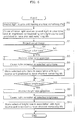
- FIG. 6 is a flow chart of processes performed by the projector device 10. The processes in FIG. 6 are performed when a user makes an input for projecting the setup image on the combiner 60 using the input unit 102.
- the prediction unit 121 predicts the remaining lifespan of each of the laser light sources 103 through 105, and predicts which light source unit has the shortest remaining life (S1).
- the laser light source 105 which outputs red laser light will be described as the light source unit predicted to have the shortest remaining life.
- the control unit 122 causes all of the laser light sources to emit light in the color tone and at brightness that corresponds with the light source unit predicted to have the shortest remaining life (S2).
- the control unit 122 is a unit which stores a table showing the relationship between the light source unit predicted to have the shortest remaining life and color tone and brightness, like the one illustrated in FIG. 7 .
- the control unit 122 causes the laser light sources 103 through 105 to emit light at a red (R), green (G), and blue (B) intensity ratio of 0:5:5.
- the control unit 122 causes the laser light sources 103 through 105 to emit light that results in the image having a brightness of 80 out of 101 increments (level 0 to 100). With this, the above ratio is maintained.
- the display control unit 110 projects the setup image on the combiner 60 (S3). This causes the characters in setup image, such as the one illustrated in FIG. 5 , to have a color tone (R:G:B) of 0:5:5 and a brightness of 80.
- the main CPU 101 When the user makes an input for changing color tone in the setup image (YES in S4), the main CPU 101 prompts the user to select a color tone (S5). Details regarding the color tone selection process (S5) will be described later.
- the control unit 122 causes the laser light sources 103 through 105 to emit light that results in the selected the color tone (S6). This changes the color tone of the setup image.
- the control unit 122 stores the selected color tone as a color tone associated with the light source unit predicted to have the shortest remaining life (here, the laser light source 105) (S7). For example, if the color tone (R:G:B) selected by the user is 1:5:5, the control unit 122 writes that value in the table shown in FIG. 7 as a color tone to be used when the light source unit predicted to have the shortest remaining life is the laser light source 105. Thereafter, the setup image is projected with the color tone selected by the user.
- the color tone (R:G:B) selected by the user is 1:5:5
- the control unit 122 writes that value in the table shown in FIG. 7 as a color tone to be used when the light source unit predicted to have the shortest remaining life is the laser light source 105. Thereafter, the setup image is projected with the color tone selected by the user.
- the main CPU 101 instructs the display control unit 110 with projection instructions for the image prompting the user to select a brightness.
- the display control unit 110 projects a brightness selection image such as the one shown in FIG. 8 on the combiner 60. The user then selects a brightness by making an input to the input unit 102 (S9).
- the control unit 122 causes the laser light sources 103 through 105 to emit light at the selected the brightness (S10). This changes the brightness of the setup image.
- the control unit 122 stores the selected brightness as a brightness associated with the light source unit predicted to have the shortest remaining life (here, the laser light source 105) (S11). For example, if the brightness selected by the user is 60, the control unit 122 writes that value in the table shown in FIG. 7 as a brightness to be used when the light source unit predicted to have the shortest remaining life is the laser light source 105. Thereafter, the setup image is projected with the brightness selected by the user.
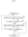
- FIG. 9 is a flow chart detailing the color tone selection process (S5 in FIG. 6 ).
- the laser light source 105 which outputs red laser light will be described as the light source unit predicted to have the shortest remaining life.
- the same processes can be used to prompt the user to select a color tone when the light source unit predicted to have the shortest remaining life is the laser light source 103 or the laser light source 104, detailed descriptions in these cases are not repeated.
- the color tone display unit 123 transmits instructions to the display control unit 110 and causes a first color tone selection image, which is an image used to prompt the user to select a color tone, to be displayed on the combiner 60 (S21).
- FIG. 10 is an example of a first color tone selection image.
- eleven bars 201 corresponding to eleven color tones from color tone 1 to color tone 11 are displayed in the color tones they correspond with.
- the R:G:B ratios of color tone 1, color tone 2, color tone 3, ..., color tone 11 are defined as (0:0:10), (0:1:9), (0:2:8), ..., (0:10:0), respectively. In other words, the proportion of R is always 0, and the G:B ratio is adjusted.
- the user for example, can select a color tone corresponding to the bar 201 where the cursor is by moving the cursor over one of the bars 201 and pressing the OK button 202. If the user does not wish to choose any of the eleven color tones, the user may select a different color tone by pressing the button 203.
- the color tone display unit 123 transmits instructions to the display control unit 110 and causes a second color tone selection image, which is an image used to prompt the user to select a color tone, to be displayed on the combiner 60 (S23).
- FIG. 11 is an example of the second color tone selection image.
- the R: G: B ratios of color tone 1, color tone 2, color tone 3, ..., color tone 7 are defined as (1:2:8), (1:3:7), (1:4:6), ..., (1:8:2), respectively.
- the proportion of R is always 1, and the G:B ratio is adjusted. Additionally, the proportion of R is set less than the proportion of G and the proportion of B.
- the user for example, can select a color tone corresponding to the bar 204 where the cursor is by moving the cursor over one of the bars 204 and pressing the OK button 205. If the user does not wish to choose any of the seven color tones, the user may return to the first color tone selection image by pressing the button 206.
- Embodiment 1 of the present invention it is possible to restrict the intensity of light output by the light source unit predicted to have the shortest remaining life from an early stage, before the laser light source becomes unusable or before the luminous efficacy thereof decreases. As such, the operating life expectancy of the projector device can be efficiently increased.
- the operating life expectancy of the projector device can be efficiently increased without decreasing the visibility of the informative image. Since the visibility of the informative image is not affected, a safe environment while driving the automobile can be maintained.
- the setup image since the user can select the color tone of a setup image, it is possible for the setup image to be projected on the combiner with a color tone that is easy to see for the user while reducing the intensity of the light source unit predicted to have the shortest remaining life.
- the intensity of the light output by the light source unit predicted to have the shortest remaining life is restricted while a setup image is being projected, and the intensity of the light output by the light source unit predicted to have the shortest remaining life is not restricted while an informative image is being projected.
- the intensity of the light output by the light source unit predicted to have the shortest remaining life is restricted even while an informative image is being projected.
- Embodiment 2 The configuration of the HUD device according to Embodiment 2 is the same as the configuration of the HUD device according to Embodiment 1. As such, a detailed description thereof will not be repeated. Hereinafter, the points different from Embodiment 1 will be discussed.
- the control unit 122 illustrated in FIG. 4 reduces the intensity of the light output by the light source unit predicted to have the shortest remaining life to below an intensity that results in the original color tone of the informative image, when the informative image indicating the route information 61 and/or the distance information 62 illustrated in FIG. 2 is displayed.
- the light source unit predicted to have the shortest remaining life is the laser light source 105 which outputs red laser light
- the original color tone (R:G:B ratio) of the image of the route information 61 is 6:4:3.
- the control unit 122 controls the intensity of the laser light output from the laser light sources 103 through 105 to achieve a color tone of 5:4:3 for the image of the route information 61 by decreasing the red proportion by one.
- the informative image that is projected on the combiner 60 appears slightly more blue than normal.
- the user can set whether a change in color tone of the informative image is allowed or not.
- the user makes an input to the input unit 102 to allow or prohibit changes in the color tone of the informative image.
- the control unit 122 changes the color tone when the informative image is displayed only when an input allowing so has been made.
- control unit 122 may change the color tone of the informative image while the automobile 50 is stopped regardless of the color tone change permission setting set by the user. It should also be noted that the control unit 122 may determine that the automobile 50 is stopped when the speed output of the speedometer is zero or below a predetermined speed.
- Embodiment 2 As is described above, with Embodiment 2, as long as the user allows for the color tone to be changed, it is possible to restrict the intensity of the light output from the light source unit predicted to have the shortest remaining life even when an informative image is being projected. As such, the operating life expectancy of the projector device can be efficiently increased.
- the operating life expectancy of the projector device can be efficiently increased while maintaining a safe environment while driving the automobile by restricting the intensity of the light output by the light source unit predicted to have the shortest remaining life while the automobile is stopped.
- the intensity of the light source unit predicted to have the shortest remaining life is restricted, but the prediction unit 121 may predict which light source unit has the longest remaining life, and the control unit 122 may increase the intensity of the light output by the light source unit predicted to have the longest remaining life to above a predetermined normal intensity while the setup image is being projected.
- the predetermined normal intensity is, for example, an intensity determined by the color tone and brightness shown in the table in FIG. 7 .
- the light source unit predicted to have the longest remaining life is preferentially used.
- the light source unit predicted to have the shortest remaining life, not the light source unit predicted to have the longest remaining life affects the operating life of the projector device. As such, by preferentially using the light source unit predicted to have the longest remaining life, it is possible to efficiently increase the operating life expectancy of the projector device while maintaining a balanced life expectancy for a plurality of light source units.
- the restricting of the intensity of the light source unit predicted to have the shortest remaining life is not limited to when a setup image is being projected.
- the intensity of the light source unit predicted to have the shortest remaining life may be restricted while a maintenance image for performing maintenance on the projector device 10 is being projected.
- the main CPU 101, the image processing unit 111, the light source control unit 112, and the mirror control unit 114 in the above described projector device 10 may more specifically be a computer system configured from a microprocessor, a ROM, a RAM, a hard disk drive, a display unit, and a keyboard, for example.
- a computer program is stored in the RAM or the hard disk drive.
- These processing units achieve their functions as a result of the microprocessor operating according to a computer program.
- the computer program is configured of a plurality of pieced together instruction codes indicating a command to the computer in order to achieve a given function.
- a portion or all of the components of each of the preceding processing units may be configured from one system large scale integration (LSI).
- LSI system large scale integration
- a system LSI is a super-multifunction LSI manufactured with a plurality of components integrated on a single chip, and specifically is a computer system configured of a microprocessor, ROM, and RAM, for example.
- the computer program is stored in the RAM.
- the system LSI achieves its function as a result of the microprocessor operating according to the computer program.
- a portion or all of the components of each of the preceding processing units may each be configured from a detachable IC card that is removable from the projector device 10 or a stand-alone module.
- the IC card and the module are computer systems configured from a microprocessor, ROM, and RAM, for example.
- the IC card and the module may include the super-multifunction LSI described above.
- the IC card and the module achieve their function as a result of the microprocessor operating according to the computer program.
- the IC card and the module may be tamperproof.
- the present invention may also be realized as the methods shown above. Moreover, the present invention may also be a computer program realizing these methods with a computer, or a digital signal of the computer program.
- the present invention may also be realized as the computer program or the digital signal stored on a non-transitory computer-readable storage recording medium, such as a flexible disk, hard disk, CD-ROM, MO, DVD, DVD-ROM, DVD-RAM, Blu-ray Disc (BD), or a semiconductor memory.
- a non-transitory computer-readable storage recording medium such as a flexible disk, hard disk, CD-ROM, MO, DVD, DVD-ROM, DVD-RAM, Blu-ray Disc (BD), or a semiconductor memory.
- the present invention may also be the digital signal stored on the above mentioned non-transitory storage recording medium.
- the present invention may also be realized by transmitting the computer program or the digital signal, for example, via an electric communication line, a wireless or wired line, a network such as the Internet, or data broadcasting.
- the present invention may be a computer system including memory storing the computer program and a microprocessor operating according to the computer program.
- the computer program or the digital signal may be implemented by an independent computer system by being stored on the non-transitory storage recording medium and transmitted, or sent via the network, for example.
- the present invention is applicable, as a projector device, to head-up display devices installed in automobiles, for example.
Landscapes
- Physics & Mathematics (AREA)
- Optics & Photonics (AREA)
- Engineering & Computer Science (AREA)
- Multimedia (AREA)
- Signal Processing (AREA)
- General Physics & Mathematics (AREA)
- Instrument Panels (AREA)
- Controls And Circuits For Display Device (AREA)
- Transforming Electric Information Into Light Information (AREA)
- Mechanical Optical Scanning Systems (AREA)
Abstract
Description
- The present invention relates to projector devices, and in particular to a projector device used in a head-up display (HUD) device or the like.
- A projector device, for example, includes a laser light source that outputs red component light (R), a laser light source that outputs green component light (G), and a laser light source that outputs blue component light (B), and projects a color image on a projection screen by guiding the light output by these laser light sources to the projection screen. As such, when any one of the laser light sources becomes unusable, the desired color image cannot be projected on the projection screen and the operating life of the projector device is determined to be expired. When the operating life of the projector device expires, the plurality of the laser light sources need to be exchanged as a unit. In other words, the laser light source having the shortest operating life is the bottleneck that determines the operating life of the projector device.
- A conventional projector device has been proposed which, when a laser light source becomes unusable due to deterioration or the luminous efficacy thereof decreases, interrupts operation of the laser light source or adjusts color tone by reducing the output power of the laser light source, in order to continue displaying images (for example, patent literature (PTL) 1).
-
- [PTL 1]
WO 2012/104967 - However, according to the conventional projector device, the color tone is not adjusted until the laser light source is already unusable or the luminous efficacy thereof has already decreased. As such, even if the color tone is adjusted, the operating life expectancy of the projector device cannot be increased since the operating life of the projector device has already expired or is close to expiring.
- The present invention has been conceived to solve the above-described problem and aims to provide a projector device capable of efficiently increasing the operating life expectancy thereof.
- In order to achieve the above goal, the projector device according to an aspect of the present invention includes: a plurality of light source units each configured to output light of a different color component; a control unit configured to control an intensity of the light output by each of the light source units; a projection unit configured to project an image on a projection screen by guiding the light output by each of the light source units to the projection screen; and a prediction unit configured to predict which light source unit among the light source units has a shortest remaining life, wherein the control unit is configured to reduce the intensity of the light output by the light source unit predicted to have the shortest remaining life to below a predetermined normal intensity.
- It is possible to predict the life expectancy of a light source unit before it becomes unusable, and even before the luminous efficacy thereof decreases. With this configuration, it is possible to restrict the intensity of light output by the light source unit predicted to have the shortest remaining life from an early stage. As such, the operating life expectancy of the projector device can be efficiently increased.
- For example, the control unit may be configured to reduce the intensity of the light output by the light source unit predicted to have the shortest remaining life to zero.
- Moreover, the control unit may be configured to, while the projection unit is projecting a setup image for configuring the projector device on the projection screen, reduce the intensity of the light output by the light source unit predicted to have the shortest remaining life to below the intensity of the light output by other ones of the light source units.
- Even if the setup image is slightly difficult to see, this does not hinder the user. As such, by restricting the intensity of the light output by the light source unit predicted to have the shortest remaining life while a setup image is being projected, it is possible to avoid restricting the intensity of the light output by the light source unit predicted to have the shortest remaining life while an informative image is being projected. Thus, the operating life expectancy of the projector device can be efficiently increased without decreasing the visibility of the informative image.
- Moreover, the projector device may further include: a color tone display unit configured to present to a user a plurality of color tones at each of which the light source unit predicted to have the shortest remaining life outputs light of less intensity than the light output by the other ones of the light source units, and prompt the user to select one of the color tones; and a storage unit configured to store the color tone selected by the user, wherein the control unit may be configured to, while the projection unit is projecting the setup image on the projection screen, control the intensity of the light output by each of the light source units to achieve the color tone stored in the storage unit.
- This makes it possible for the setup image to be projected on the projection screen with a color tone that is easy to see for the user while reducing the intensity of the light source unit predicted to have the shortest remaining life.
- Moreover, the projector device may further include an input unit configured to receive a user input for allowing a change in color tone of an informative image to be projected on the projection screen, wherein when the input unit receives the user input for allowing a change in color tone of the informative image, the control unit may be configured to, while the projection unit is projecting the informative image on the projection screen, reduce the intensity of the light output by the light source unit predicted to have the shortest remaining life to below an intensity resulting in an original color tone of the informative image.
- With this, as long as the user allows for the color tone to be changed, it is possible to restrict the intensity of the light output from the light source unit predicted to have the shortest remaining life even when an informative image is being projected. As such, the operating life expectancy of the projector device can be efficiently increased.
- Moreover, the projector device may be installed in a vehicle, and the control unit may be configured to, while the vehicle is stopped and the projection unit is projecting an informative image that provides assistance in driving the vehicle, reduce the intensity of the light output by the light source unit predicted to have the shortest remaining life to below an intensity resulting in an original color tone of the informative image.
- While the automobile is in motion, it is necessary to make the informative images easy to see since the user is concentrating on driving. However, when the automobile is stopped, there is no problem in making the informative images slightly more difficult to see since the user is not mentally occupied with driving. As such, the operating life expectancy of the projector device can be efficiently increased while maintaining a safe environment while driving by restricting the intensity of the light output by the light source unit predicted to have the shortest remaining life while the automobile is stopped.
- Moreover, the prediction unit may further be configured to predict which light source unit among the light source units has a longest remaining life, and the control unit may be configured to, while the projection unit is projecting the setup image on the projection screen, increase the intensity of the light output by the light source unit predicted to have the longest remaining life to above the predetermined normal intensity.
- With this, the light source unit predicted to have the longest remaining life is preferentially used. The light source unit predicted to have the shortest remaining life, not the light source unit predicted to have the longest remaining life affects the operating life of the projector device. As such, by preferentially using the light source unit predicted to have the longest remaining life, it is possible to efficiently increase the operating life expectancy of the projector device while maintaining a balanced life expectancy for a plurality of light source units.
- It should be noted that the present invention can not only be implemented as a projector device including characterizing processing units such as those described here, but as a projector device control method in which the processes performed by the characterizing processing units included in the projector device are implemented as steps. Moreover, the present invention can be implemented as a computer program for making a computer perform as the characterizing processing units included in the projector device, or as a computer program that causes a computer to execute the characterizing steps included in the projector device control method. It goes without saying that the computer program can be circulated on a non-transitory computer-readable storage recording medium such as a compact disc-read only memory (CD-ROM) or over a communications network such as the Internet.
- According the present invention, it is possible to provide a projector device capable of efficiently increasing the operating life expectancy thereof.
-
- [
FIG. 1] FIG. 1 is an example of how the HUD device according toEmbodiment 1 is installed. - [
FIG. 2] FIG. 2 illustrates an example of what the user sees when looking through the windshield of the automobile. - [
FIG. 3] FIG. 3 is a block diagram illustrating the HUD device hardware configuration. - [
FIG. 4] FIG. 4 is a block diagram illustrating, as a functional configuration, processes executed by a main CPU when a computer program is executed by the main CPU. - [
FIG. 5] FIG. 5 is an example of a setup image for configuring color tone, brightness, contrast, and resolution. - [
FIG. 6] FIG. 6 is a flow chart of processes performed by the projector device. - [
FIG. 7] FIG. 7 is an example of a table illustrating the relationship between the light source unit predicted to have the shortest remaining life, and color tone and brightness. - [
FIG. 8] FIG. 8 illustrates an example of an image used for brightness adjustment. - [
FIG. 9] FIG. 9 is a flow chart detailing the color tone selection process (S5 inFIG. 6 ). - [
FIG. 10] FIG. 10 is an example of a first color tone selection image. - [
FIG. 11] FIG. 11 is an example of a second color tone selection image. - Hereinafter, certain exemplary embodiments are described in greater detail with reference to the accompanying drawings. It should be noted that the exemplary embodiments described below show a specific example of the present invention. The numerical values, shapes, materials, structural elements, the arrangement and connection of the structural elements, steps, the processing order of the steps etc. shown in the following exemplary embodiments are mere examples, and therefore do not limit the present invention. Among the structural elements in the following exemplary embodiments, structural elements not recited in any one of the independent claims are described as arbitrary structural elements.
- Hereinafter, a head-up display (hereinafter simply referred to as HUD) device will be described as one example of the projector device according to the present invention. A HUD device is a system which projects an image on the windshield of an automobile such that a virtual image appears in front of the windshield (i.e. outside the automobile), in the field of view of the user (driver). In
Embodiment 1, the description will focus on the processes for increasing the operating life expectancy of the HUD device. -
FIG. 1 is an example of how the HUD device according toEmbodiment 1 of the present invention is installed. AsFIG. 1 illustrates, theHUD device 1 includes aprojector device 10 and a combiner 60 (which includes the transparent display plate). - The
projector device 10 is installed in a transport vehicle, such as theautomobile 50. For example, theprojector device 10 is installed on the dashboard of theautomobile 50. Thecombiner 60 is a projection screen installed on a portion of thewindshield 20 of theautomobile 50. Theprojector device 10 projects an image on thecombiner 60 by shining light on thecombiner 60. Since thecombiner 60 is, for example, a polarizing element, an element that selectively passes certain wavelengths, or a one-way mirror, the image projected by theprojector device 10 is superimposed on the scenery outside of the automobile. It should be noted that there are instances when thewindshield 20 itself possesses the functions of thecombiner 60. -
FIG. 2 illustrates an example of what the user sees when looking through thewindshield 20 of the automobile. As described above, thecombiner 60 is installed on thewindshield 20. An image projected by theprojector device 10 is displayed on thecombiner 60. As is illustrated inFIG. 2 , theprojector device 10 includes the function of displaying, for example, navigation information (such as the route to a destination) or automobile information (such as gas mileage) on thecombiner 60. For example, theprojector device 10 displays, on thecombiner 60, an image showing route information 61 (Osaka, Kobe, and the arrows pointing the way to Osaka or Kobe) to a destination and distance information 62 (1.0 km) on distance to a destination (this kind of image is one example of an "informative image"). As is illustrated inFIG. 2 , since the image projected by theprojector device 10 is displayed among the scenery to the front of the automobile, the user driving theautomobile 50 can view information helpful to driving without changing his or her line of sight. -
FIG. 3 is a block diagram illustrating theHUD device 1 hardware configuration. - The
projector device 10 includes amain CPU 101, aninput unit 102,laser light sources 103 through 105 (the plurality of light source units), abeam splitter 106, abeam splitter 107, alens 108, aMEMS mirror 109, and adisplay control unit 110. - The
main CPU 101 controls each component in theprojector device 10. For example, themain CPU 101 controls the intensity of thelaser light sources 103 through 105 to increase the operating life expectancy of theprojector device 10. The intensity control processes performed by themain CPU 101 will be described later. - The
input unit 102 receives inputs from the user, such as inputs for turning on the HUD device 1 (the projector device 10), changing the projection angle of the image, and changing the color tone or brightness of the image. Theinput unit 102 may be, for example, a hardware button or a software button, and may be a configured of a remote control and receiver which receives radio waves transmitted from the remote control. - The
laser light source 103 is a laser diode that emits blue laser light on theMEMS mirror 109 through thebeam splitter 106 and thelens 108. - The
laser light source 104 and thelaser light source 105 are laser diodes that emit a green laser light and a red laser light, respectively, on theMEMS mirror 109 through thebeam splitter 107, thebeam splitter 106, and thelens 108. - The
laser light sources 103 through 105 greatly influence the operating life of theprojector device 10. In other words, at the point in time any given one of the laser light sources becomes unusable, theprojector device 10 can no longer project a full color image on thecombiner 60. For this reason, when this occurs, the operating life of theprojector device 10 is deemed to be expired. - As is illustrated in
FIG. 2 , theMEMS mirror 109 is driven and scans the laser light in two axes: horizontal (X axis direction) and vertical (Y axis direction). TheMEMS mirror 109 is also capable of horizontal high-speed scanning by resonant driving and vertical low-speed scanning by direct current driving. Driving control of theMEMS mirror 109 is performed by adisplay control unit 110, which will be described next. - The
display control unit 110 includes animage processing unit 111, a lightsource control unit 112, a laser diode (LD)driver 113, amirror control unit 114, and amirror driver 115. - The
image processing unit 111 performs controlling for projection of the image on thecombiner 60 based on an image signal input from an external source. More specifically, based on the image signal, theimage processing unit 111 controls the driving of theMEMS mirror 109 via themirror control unit 114 and controls the emission of the laser light from thelaser light sources 103 through 105 via the lightsource control unit 112. - Based on the control by the
image processing unit 111, the lightsource control unit 112 controls theLD driver 113 and emission of laser light from thelaser light sources 103 through 105. More specifically, the lightsource control unit 112 performs controlling for causing thelaser light sources 103 through 105 to emit laser light of color corresponding to each pixel of the image in synchronization with the scanning of the image by theMEMS mirror 109. - The
LD driver 113 adjusts the intensity of thelaser light sources 103 through 105 by supplying driving current to thelaser light sources 103 through 105. - Based on the control by the
image processing unit 111, themirror control unit 114 controls themirror driver 115 and controls the driving of theMEMS mirror 109. In other words, themirror control unit 114 scans thecombiner 60 with the laser light shining from thelaser light sources 103 through 105 by controlling the tilt of theMEMS mirror 109. With this, themirror control unit 114 projects the image on thecombiner 60. In other words, an image projected on thecombiner 60 that shows, for example, theroute information 61 and thedistance information 62, is generated by the image-generatinglaser light sources 103 through 105. - The
mirror driver 115 changes the tilt of theMEMS mirror 109 by supplying a drive signal to theMEMS mirror 109. - Next, processes performed by the
main CPU 101 that are characteristic toEmbodiment 1 will be described. As is illustrated inFIG. 3 , themain CPU 101 operates according to aprogram 101a. -
FIG. 4 is a block diagram illustrating, as a functional configuration, processes executed by themain CPU 101 when theprogram 101a is executed by themain CPU 101. In other words, when theprogram 101a is executed by themain CPU 101, themain CPU 101 includes, as processing units realized in a functional manner, aprediction unit 121, acontrol unit 122, and a colortone display unit 123. - The
prediction unit 121 predicts which of thelaser light sources 103 through 105 has the shortest remaining life. The method of predicting which laser light source has the shortest remaining life is not limited to a particular method. For example, in the case that the average service life of thelaser light sources 103 through 105 is known in advance, theprediction unit 121 may predict the remaining life by subtracting the cumulative use time of the laser light source from the known service life, for each laser light source. For example, when the service life of thelaser light source 103 is 10,000 hours and the accumulated use time of thelaser light source 103 is 7,000 hours, theprediction unit 121 predicts that the remaining lifespan of thelaser light source 103 is 3,000 hours. It should be noted that since information on whether thelaser light source 103 is being used or not is obtainable from theLD driver 113, theprediction unit 121 can calculate the accumulated use time of each laser light source based on that information. - The
control unit 122 controls the intensity of the laser light output from thelaser light sources 103 through 105. In other words, via the lightsource control unit 112, thecontrol unit 122 adjusts the color tone and/or the brightness of the image displayed on thecombiner 60 by controlling the intensity of the laser light output from thelaser light sources 103 through 105. More specifically, thecontrol unit 122 reduces the intensity of the light output by the light source unit predicted to have the shortest remaining life by theprediction unit 121 to below a predetermined normal intensity. Preferably, thecontrol unit 122 reduces the intensity of the light output by the light source unit predicted to have the shortest remaining life to zero. It should be noted that theprediction unit 121 may restrict the intensity of the light source unit predicted to have the shortest remaining life while a setup image for configuring theprojector device 10 is being projected on thecombiner 60. In other words, theprediction unit 121 may restrict the intensity of the light source unit predicted to have the shortest remaining life while a setup image for adjusting color tone, brightness, contrast, and resolution, such as the image illustrated inFIG. 5 , is being projected on thecombiner 60. - The color
tone display unit 123 presents to the user a plurality of color tones at each of which the light source unit predicted to have the shortest remaining life outputs light of less intensity than the light output by other ones of the light source units, and prompts the user to select one of the color tones. Thecontrol unit 122 controls the intensity of the laser light output from thelaser light sources 103 through 105 to achieve the selected the color tone. With this, the intensity of the light source unit predicted to have the shortest remaining life is restricted. - Hereinafter, the processing performed by the
projector device 10 will be described in detail. -
FIG. 6 is a flow chart of processes performed by theprojector device 10. The processes inFIG. 6 are performed when a user makes an input for projecting the setup image on thecombiner 60 using theinput unit 102. - When the
input unit 102 receives an input for projecting the setup image, theprediction unit 121 predicts the remaining lifespan of each of thelaser light sources 103 through 105, and predicts which light source unit has the shortest remaining life (S1). In the following description, thelaser light source 105 which outputs red laser light will be described as the light source unit predicted to have the shortest remaining life. - The
control unit 122 causes all of the laser light sources to emit light in the color tone and at brightness that corresponds with the light source unit predicted to have the shortest remaining life (S2). In other words, thecontrol unit 122 is a unit which stores a table showing the relationship between the light source unit predicted to have the shortest remaining life and color tone and brightness, like the one illustrated inFIG. 7 . For example, when the light source unit predicted to have the shortest remaining life is thelaser light source 105 that outputs red laser light, thecontrol unit 122 causes thelaser light sources 103 through 105 to emit light at a red (R), green (G), and blue (B) intensity ratio of 0:5:5. Moreover, thecontrol unit 122 causes thelaser light sources 103 through 105 to emit light that results in the image having a brightness of 80 out of 101 increments (level 0 to 100). With this, the above ratio is maintained. - The
display control unit 110 projects the setup image on the combiner 60 (S3). This causes the characters in setup image, such as the one illustrated inFIG. 5 , to have a color tone (R:G:B) of 0:5:5 and a brightness of 80. - When the user makes an input for changing color tone in the setup image (YES in S4), the
main CPU 101 prompts the user to select a color tone (S5). Details regarding the color tone selection process (S5) will be described later. - The
control unit 122 causes thelaser light sources 103 through 105 to emit light that results in the selected the color tone (S6). This changes the color tone of the setup image. - Moreover, the
control unit 122 stores the selected color tone as a color tone associated with the light source unit predicted to have the shortest remaining life (here, the laser light source 105) (S7). For example, if the color tone (R:G:B) selected by the user is 1:5:5, thecontrol unit 122 writes that value in the table shown inFIG. 7 as a color tone to be used when the light source unit predicted to have the shortest remaining life is thelaser light source 105. Thereafter, the setup image is projected with the color tone selected by the user. - When the user makes an input for adjusting the brightness of the setup image (YES in S8), the
main CPU 101 instructs thedisplay control unit 110 with projection instructions for the image prompting the user to select a brightness. In response to the projection instructions, thedisplay control unit 110 projects a brightness selection image such as the one shown inFIG. 8 on thecombiner 60. The user then selects a brightness by making an input to the input unit 102 (S9). - The
control unit 122 causes thelaser light sources 103 through 105 to emit light at the selected the brightness (S10). This changes the brightness of the setup image. - Moreover, the
control unit 122 stores the selected brightness as a brightness associated with the light source unit predicted to have the shortest remaining life (here, the laser light source 105) (S11). For example, if the brightness selected by the user is 60, thecontrol unit 122 writes that value in the table shown inFIG. 7 as a brightness to be used when the light source unit predicted to have the shortest remaining life is thelaser light source 105. Thereafter, the setup image is projected with the brightness selected by the user. - Next, details regarding the color tone selection process (S5 in
FIG. 6 ) will be described.FIG. 9 is a flow chart detailing the color tone selection process (S5 inFIG. 6 ). Here, thelaser light source 105 which outputs red laser light will be described as the light source unit predicted to have the shortest remaining life. As the same processes can be used to prompt the user to select a color tone when the light source unit predicted to have the shortest remaining life is thelaser light source 103 or thelaser light source 104, detailed descriptions in these cases are not repeated. - The color
tone display unit 123 transmits instructions to thedisplay control unit 110 and causes a first color tone selection image, which is an image used to prompt the user to select a color tone, to be displayed on the combiner 60 (S21).FIG. 10 is an example of a first color tone selection image. In the first color tone selection image, elevenbars 201 corresponding to eleven color tones fromcolor tone 1 tocolor tone 11 are displayed in the color tones they correspond with. The R:G:B ratios ofcolor tone 1,color tone 2,color tone 3, ...,color tone 11 are defined as (0:0:10), (0:1:9), (0:2:8), ..., (0:10:0), respectively. In other words, the proportion of R is always 0, and the G:B ratio is adjusted. The user, for example, can select a color tone corresponding to thebar 201 where the cursor is by moving the cursor over one of thebars 201 and pressing theOK button 202. If the user does not wish to choose any of the eleven color tones, the user may select a different color tone by pressing thebutton 203. - When the user selects a color tone by pressing the OK button 202 (YES in S22), the color tone selection process (S5 in
FIG. 6 ) ends. - When the user does not select a color tone and presses the button 203 (NO in S22), the color
tone display unit 123 transmits instructions to thedisplay control unit 110 and causes a second color tone selection image, which is an image used to prompt the user to select a color tone, to be displayed on the combiner 60 (S23).FIG. 11 is an example of the second color tone selection image. In the second color tone selection image, sevenbars 204 corresponding to seven color tones fromcolor tone 1 tocolor tone 7 are displayed in the color tones they correspond with. The R: G: B ratios ofcolor tone 1,color tone 2,color tone 3, ...,color tone 7 are defined as (1:2:8), (1:3:7), (1:4:6), ..., (1:8:2), respectively. In other words, the proportion of R is always 1, and the G:B ratio is adjusted. Additionally, the proportion of R is set less than the proportion of G and the proportion of B. The user, for example, can select a color tone corresponding to thebar 204 where the cursor is by moving the cursor over one of thebars 204 and pressing theOK button 205. If the user does not wish to choose any of the seven color tones, the user may return to the first color tone selection image by pressing thebutton 206. - When the user selects a color tone by pressing the OK button 205 (YES in S24), the color tone selection process (S5 in
FIG. 6 ) ends. - When the user does not select a color tone and presses the button 206 (NO in S24), the processing is repeated from S21.
- As described above, according to
Embodiment 1 of the present invention, it is possible to restrict the intensity of light output by the light source unit predicted to have the shortest remaining life from an early stage, before the laser light source becomes unusable or before the luminous efficacy thereof decreases. As such, the operating life expectancy of the projector device can be efficiently increased. - Moreover, by restricting the intensity of the light output by the light source unit predicted to have the shortest remaining life while a setup image is being projected, it is possible to avoid restricting the intensity of the light output by the light source unit predicted to have the shortest remaining life while the informative image is being projected. As such, the operating life expectancy of the projector device can be efficiently increased without decreasing the visibility of the informative image. Since the visibility of the informative image is not affected, a safe environment while driving the automobile can be maintained.
- Additionally, since the user can select the color tone of a setup image, it is possible for the setup image to be projected on the combiner with a color tone that is easy to see for the user while reducing the intensity of the light source unit predicted to have the shortest remaining life.
- In
Embodiment 1, the intensity of the light output by the light source unit predicted to have the shortest remaining life is restricted while a setup image is being projected, and the intensity of the light output by the light source unit predicted to have the shortest remaining life is not restricted while an informative image is being projected. However, InEmbodiment 2, the intensity of the light output by the light source unit predicted to have the shortest remaining life is restricted even while an informative image is being projected. - The configuration of the HUD device according to
Embodiment 2 is the same as the configuration of the HUD device according toEmbodiment 1. As such, a detailed description thereof will not be repeated. Hereinafter, the points different fromEmbodiment 1 will be discussed. - The
control unit 122 illustrated inFIG. 4 reduces the intensity of the light output by the light source unit predicted to have the shortest remaining life to below an intensity that results in the original color tone of the informative image, when the informative image indicating theroute information 61 and/or thedistance information 62 illustrated inFIG. 2 is displayed. For example, assume the light source unit predicted to have the shortest remaining life is thelaser light source 105 which outputs red laser light, and the original color tone (R:G:B ratio) of the image of theroute information 61 is 6:4:3. In this case, thecontrol unit 122 controls the intensity of the laser light output from thelaser light sources 103 through 105 to achieve a color tone of 5:4:3 for the image of theroute information 61 by decreasing the red proportion by one. With this, the informative image that is projected on thecombiner 60 appears slightly more blue than normal. - It should be noted that it is possible for the user to set whether a change in color tone of the informative image is allowed or not. In other words, the user makes an input to the
input unit 102 to allow or prohibit changes in the color tone of the informative image. Thecontrol unit 122 changes the color tone when the informative image is displayed only when an input allowing so has been made. - It should be noted that the
control unit 122 may change the color tone of the informative image while theautomobile 50 is stopped regardless of the color tone change permission setting set by the user. It should also be noted that thecontrol unit 122 may determine that theautomobile 50 is stopped when the speed output of the speedometer is zero or below a predetermined speed. - As is described above, with
Embodiment 2, as long as the user allows for the color tone to be changed, it is possible to restrict the intensity of the light output from the light source unit predicted to have the shortest remaining life even when an informative image is being projected. As such, the operating life expectancy of the projector device can be efficiently increased. - Moreover, while the automobile is in motion, it is necessary to make the informative images easy to see since the user is concentrating on driving. However, when the automobile is stopped, there is no problem in making the informative image slightly more difficult to see since the user is not mentally occupied with driving. As such, the operating life expectancy of the projector device can be efficiently increased while maintaining a safe environment while driving the automobile by restricting the intensity of the light output by the light source unit predicted to have the shortest remaining life while the automobile is stopped.
- Hereinbefore the HUD device according to the embodiments of the present invention has been described, but the present invention is not limited to these embodiments.
- For example, in the above embodiments, the intensity of the light source unit predicted to have the shortest remaining life is restricted, but the
prediction unit 121 may predict which light source unit has the longest remaining life, and thecontrol unit 122 may increase the intensity of the light output by the light source unit predicted to have the longest remaining life to above a predetermined normal intensity while the setup image is being projected. Here, the predetermined normal intensity is, for example, an intensity determined by the color tone and brightness shown in the table inFIG. 7 . With this, the light source unit predicted to have the longest remaining life is preferentially used. The light source unit predicted to have the shortest remaining life, not the light source unit predicted to have the longest remaining life affects the operating life of the projector device. As such, by preferentially using the light source unit predicted to have the longest remaining life, it is possible to efficiently increase the operating life expectancy of the projector device while maintaining a balanced life expectancy for a plurality of light source units. - Additionally, the restricting of the intensity of the light source unit predicted to have the shortest remaining life is not limited to when a setup image is being projected. For example, the intensity of the light source unit predicted to have the shortest remaining life may be restricted while a maintenance image for performing maintenance on the
projector device 10 is being projected. - Moreover, the
main CPU 101, theimage processing unit 111, the lightsource control unit 112, and themirror control unit 114 in the above describedprojector device 10 may more specifically be a computer system configured from a microprocessor, a ROM, a RAM, a hard disk drive, a display unit, and a keyboard, for example. A computer program is stored in the RAM or the hard disk drive. These processing units achieve their functions as a result of the microprocessor operating according to a computer program. Here, the computer program is configured of a plurality of pieced together instruction codes indicating a command to the computer in order to achieve a given function. - A portion or all of the components of each of the preceding processing units may be configured from one system large scale integration (LSI). A system LSI is a super-multifunction LSI manufactured with a plurality of components integrated on a single chip, and specifically is a computer system configured of a microprocessor, ROM, and RAM, for example. The computer program is stored in the RAM. The system LSI achieves its function as a result of the microprocessor operating according to the computer program.
- A portion or all of the components of each of the preceding processing units may each be configured from a detachable IC card that is removable from the
projector device 10 or a stand-alone module. The IC card and the module are computer systems configured from a microprocessor, ROM, and RAM, for example. The IC card and the module may include the super-multifunction LSI described above. The IC card and the module achieve their function as a result of the microprocessor operating according to the computer program. The IC card and the module may be tamperproof. - The present invention may also be realized as the methods shown above. Moreover, the present invention may also be a computer program realizing these methods with a computer, or a digital signal of the computer program.
- Moreover, the present invention may also be realized as the computer program or the digital signal stored on a non-transitory computer-readable storage recording medium, such as a flexible disk, hard disk, CD-ROM, MO, DVD, DVD-ROM, DVD-RAM, Blu-ray Disc (BD), or a semiconductor memory. The present invention may also be the digital signal stored on the above mentioned non-transitory storage recording medium.
- Moreover, the present invention may also be realized by transmitting the computer program or the digital signal, for example, via an electric communication line, a wireless or wired line, a network such as the Internet, or data broadcasting.
- Moreover, the present invention may be a computer system including memory storing the computer program and a microprocessor operating according to the computer program.
- Moreover, the computer program or the digital signal may be implemented by an independent computer system by being stored on the non-transitory storage recording medium and transmitted, or sent via the network, for example.
- Furthermore, the preceding embodiments and the preceding variation examples may be individually combined.
- Although the present invention has been described and illustrated in detail, it is clearly understood that the same is by way of example only and is not to be taken by way of limitation, the scope of the present invention being limited only by the terms of the appended claims.
- The present invention is applicable, as a projector device, to head-up display devices installed in automobiles, for example.
-
- 1 HUD device
- 10 projector device
- 20 windshield
- 60 combiner
- 61 route information
- 62 distance information
- 101 main CPU
- 101a program
- 102 input unit
- 103 through 105 laser light source
- 106, 107 beam splitter
- 108 lens
- 109 MEMS mirror
- 110 display control unit
- 111 image processing unit
- 112 light source control unit
- 113 LD driver
- 114 mirror control unit
- 115 mirror driver
- 121 prediction unit
- 122 control unit
- 123 color tone display unit
- 201, 204 bar
- 202, 205 OK button
- 203, 206 button
Claims (9)
- A projector device comprising:a plurality of light source units each configured to output light of a different color component;a control unit configured to control an intensity of the light output by each of the light source units;a projection unit configured to project an image on a projection screen by guiding the light output by each of the light source units to the projection screen; anda prediction unit configured to predict which light source unit among the light source units has a shortest remaining life,wherein the control unit is configured to reduce the intensity of the light output by the light source unit predicted to have the shortest remaining life to below a predetermined normal intensity.
- The projector device according to Claim 1,
wherein the control unit is configured to reduce the intensity of the light output by the light source unit predicted to have the shortest remaining life to zero. - The projector device according to Claim 1 or 2,
wherein the control unit is configured to, while the projection unit is projecting a setup image for configuring the projector device on the projection screen, reduce the intensity of the light output by the light source unit predicted to have the shortest remaining life to below the intensity of the light output by other ones of the light source units. - The projector device according to Claim 3, further comprising:a color tone display unit configured to present to a user a plurality of color tones at each of which the light source unit predicted to have the shortest remaining life outputs light of less intensity than the light output by the other ones of the light source units, and prompt the user to select one of the color tones; anda storage unit configured to store the color tone selected by the user,wherein the control unit is configured to, while the projection unit is projecting the setup image on the projection screen, control the intensity of the light output by each of the light source units to achieve the color tone stored in the storage unit.
- The projector device according to any one of Claims 1 to 4, further comprising
an input unit configured to receive a user input for allowing a change in color tone of an informative image to be projected on the projection screen,
wherein when the input unit receives the user input for allowing a change in color tone of the informative image, the control unit is configured to, while the projection unit is projecting the informative image on the projection screen, reduce the intensity of the light output by the light source unit predicted to have the shortest remaining life to below an intensity resulting in an original color tone of the informative image. - The projector device according to any one of Claims 1 to 4, wherein the projector device is installed in a vehicle, and the control unit is configured to, while the vehicle is stopped and the projection unit is projecting an informative image that provides assistance in driving the vehicle, reduce the intensity of the light output by the light source unit predicted to have the shortest remaining life to below an intensity resulting in an original color tone of the informative image.
- The projector device according to Claim 3 or 4,
wherein the prediction unit is further configured to predict which light source unit among the light source units has a longest remaining life, and
the control unit is configured to, while the projection unit is projecting the setup image on the projection screen, increase the intensity of the light output by the light source unit predicted to have the longest remaining life to above the predetermined normal intensity. - A head-up display device comprising:the projector device according to any one of Claims 1 to 7; anda transparent display plate onto which the image is projected.
- A projector device control method comprising:predicting, among a plurality of light source units that each output light of a different color component, which light source unit has a shortest remaining life; andreducing the intensity of the light output by the light source unit predicted to have the shortest remaining life to below a predetermined normal intensity.
Applications Claiming Priority (1)
| Application Number | Priority Date | Filing Date | Title |
|---|---|---|---|
| JP2013072101A JP2014197087A (en) | 2013-03-29 | 2013-03-29 | Projector device, head-up display device, and method of controlling projector device |
Publications (1)
| Publication Number | Publication Date |
|---|---|
| EP2784582A1 true EP2784582A1 (en) | 2014-10-01 |
Family
ID=50389234
Family Applications (1)
| Application Number | Title | Priority Date | Filing Date |
|---|---|---|---|
| EP20140160616 Withdrawn EP2784582A1 (en) | 2013-03-29 | 2014-03-19 | Projector device, head-up display device, and projector device control method |
Country Status (3)
| Country | Link |
|---|---|
| US (1) | US20140293230A1 (en) |
| EP (1) | EP2784582A1 (en) |
| JP (1) | JP2014197087A (en) |
Cited By (1)
| Publication number | Priority date | Publication date | Assignee | Title |
|---|---|---|---|---|
| WO2020141173A1 (en) * | 2019-01-04 | 2020-07-09 | Eyelights | Film for a curved projection medium of a head-up display system |
Families Citing this family (7)
| Publication number | Priority date | Publication date | Assignee | Title |
|---|---|---|---|---|
| US11030778B2 (en) * | 2014-03-31 | 2021-06-08 | Healthy.Io Ltd. | Methods and apparatus for enhancing color vision and quantifying color interpretation |
| JP6544507B2 (en) * | 2015-02-09 | 2019-07-17 | 日本精機株式会社 | Head-up display device |
| CN107924668B (en) * | 2015-08-26 | 2021-02-19 | 富士胶片株式会社 | Projection type display device |
| KR102070211B1 (en) * | 2017-04-06 | 2020-01-28 | 엘지전자 주식회사 | Car Head Up Display Device |
| JP2020024560A (en) * | 2018-08-07 | 2020-02-13 | 本田技研工業株式会社 | Display device, display control method, and program |
| CN110855963B (en) * | 2018-08-21 | 2022-03-08 | 视联动力信息技术股份有限公司 | Video data projection method and device |
| JP2025114369A (en) * | 2024-01-24 | 2025-08-05 | マクセル株式会社 | Virtual image display device |
Citations (4)
| Publication number | Priority date | Publication date | Assignee | Title |
|---|---|---|---|---|
| EP1098550A2 (en) * | 1999-11-05 | 2001-05-09 | Avix Inc. | Led lamp |
| JP2002319734A (en) * | 2001-04-20 | 2002-10-31 | Toshiba Corp | Laser light source device |
| US20100302515A1 (en) * | 2009-05-28 | 2010-12-02 | Honeywood Technologies, Llc | Projection-type display and control thereof |
| WO2012104967A1 (en) | 2011-01-31 | 2012-08-09 | パイオニア株式会社 | Image display device, image display method, image display program |
Family Cites Families (2)
| Publication number | Priority date | Publication date | Assignee | Title |
|---|---|---|---|---|
| US20050259223A1 (en) * | 2004-05-21 | 2005-11-24 | Hopman Nicholas C | Projection display |
| WO2012104968A1 (en) * | 2011-01-31 | 2012-08-09 | パイオニア株式会社 | Image display device, image display method, image display program |
-
2013
- 2013-03-29 JP JP2013072101A patent/JP2014197087A/en active Pending
-
2014
- 2014-03-19 EP EP20140160616 patent/EP2784582A1/en not_active Withdrawn
- 2014-03-28 US US14/228,476 patent/US20140293230A1/en not_active Abandoned
Patent Citations (4)
| Publication number | Priority date | Publication date | Assignee | Title |
|---|---|---|---|---|
| EP1098550A2 (en) * | 1999-11-05 | 2001-05-09 | Avix Inc. | Led lamp |
| JP2002319734A (en) * | 2001-04-20 | 2002-10-31 | Toshiba Corp | Laser light source device |
| US20100302515A1 (en) * | 2009-05-28 | 2010-12-02 | Honeywood Technologies, Llc | Projection-type display and control thereof |
| WO2012104967A1 (en) | 2011-01-31 | 2012-08-09 | パイオニア株式会社 | Image display device, image display method, image display program |
Cited By (2)
| Publication number | Priority date | Publication date | Assignee | Title |
|---|---|---|---|---|
| WO2020141173A1 (en) * | 2019-01-04 | 2020-07-09 | Eyelights | Film for a curved projection medium of a head-up display system |
| FR3091595A1 (en) * | 2019-01-04 | 2020-07-10 | Eyelights | Film for projection support of a head-up display system |
Also Published As
| Publication number | Publication date |
|---|---|
| JP2014197087A (en) | 2014-10-16 |
| US20140293230A1 (en) | 2014-10-02 |
Similar Documents
| Publication | Publication Date | Title |
|---|---|---|
| US20140293230A1 (en) | Projector device, head-up display device, and projector device control method | |
| US10628020B2 (en) | Projection type display device | |
| US10011177B2 (en) | Projection display system and method of controlling projection display device | |
| US10502962B2 (en) | Projection type display device and projection control method | |
| JP6406739B2 (en) | LIGHTING DEVICE, PROJECTOR, DISPLAY SYSTEM, AND LIGHT SOURCE ADJUSTING METHOD | |
| US8184136B2 (en) | Image display device provided with multiple light sources emitting different colors to display color images in color sequential display method | |
| JP6194432B2 (en) | Projection type display device and light source control method thereof | |
| WO2016103937A1 (en) | Projection-type display device, safe-driving support method, and safe-driving support program | |
| WO2017138321A1 (en) | Image display device, car onboard system, and image display method | |
| JP2017106976A (en) | Projector | |
| JP2017097153A (en) | Projector | |
| JP2015162526A (en) | Laser light source driving device and display device | |
| JP2014197044A (en) | Projector, head-up display device, and method for controlling projector | |
| JP2018072758A (en) | Light projection device | |
| WO2019064638A1 (en) | Virtual image display device | |
| US9952492B2 (en) | Projection-type display device and light source control method therefor | |
| JP2014197052A (en) | Projector device and head-up display device | |
| JP2017015974A (en) | Projection device | |
| EP2784579A1 (en) | Head-up display device and display method of head-up display device | |
| JP2017079132A (en) | Light output control unit and light projection device | |
| JP2017227806A (en) | Display device | |
| JP2017202762A (en) | Display image projection device and display image projection method | |
| EP2852160A1 (en) | Projector and method for compensating for amount of laser light | |
| JP2016025430A (en) | Projector and head-up display device | |
| WO2019230094A1 (en) | Head-up display device |
Legal Events
| Date | Code | Title | Description |
|---|---|---|---|
| 17P | Request for examination filed |
Effective date: 20140319 |
|
| AK | Designated contracting states |
Kind code of ref document: A1 Designated state(s): AL AT BE BG CH CY CZ DE DK EE ES FI FR GB GR HR HU IE IS IT LI LT LU LV MC MK MT NL NO PL PT RO RS SE SI SK SM TR |
|
| AX | Request for extension of the european patent |
Extension state: BA ME |
|
| PUAI | Public reference made under article 153(3) epc to a published international application that has entered the european phase |
Free format text: ORIGINAL CODE: 0009012 |
|
| R17P | Request for examination filed (corrected) |
Effective date: 20150331 |
|
| RBV | Designated contracting states (corrected) |
Designated state(s): AL AT BE BG CH CY CZ DE DK EE ES FI FR GB GR HR HU IE IS IT LI LT LU LV MC MK MT NL NO PL PT RO RS SE SI SK SM TR |
|
| STAA | Information on the status of an ep patent application or granted ep patent |
Free format text: STATUS: THE APPLICATION HAS BEEN WITHDRAWN |
|
| 18W | Application withdrawn |
Effective date: 20151211 |