EP2784545A1 - Apparatus for tracking an animate being, in particular a bird, and operation of such apparatus - Google Patents
Apparatus for tracking an animate being, in particular a bird, and operation of such apparatus Download PDFInfo
- Publication number
- EP2784545A1 EP2784545A1 EP20130001667 EP13001667A EP2784545A1 EP 2784545 A1 EP2784545 A1 EP 2784545A1 EP 20130001667 EP20130001667 EP 20130001667 EP 13001667 A EP13001667 A EP 13001667A EP 2784545 A1 EP2784545 A1 EP 2784545A1
- Authority
- EP
- European Patent Office
- Prior art keywords
- data
- animate
- monitoring device
- tracker
- time
- Prior art date
- Legal status (The legal status is an assumption and is not a legal conclusion. Google has not performed a legal analysis and makes no representation as to the accuracy of the status listed.)
- Granted
Links
Images




Classifications
-
- G—PHYSICS
- G01—MEASURING; TESTING
- G01S—RADIO DIRECTION-FINDING; RADIO NAVIGATION; DETERMINING DISTANCE OR VELOCITY BY USE OF RADIO WAVES; LOCATING OR PRESENCE-DETECTING BY USE OF THE REFLECTION OR RERADIATION OF RADIO WAVES; ANALOGOUS ARRANGEMENTS USING OTHER WAVES
- G01S19/00—Satellite radio beacon positioning systems; Determining position, velocity or attitude using signals transmitted by such systems
- G01S19/01—Satellite radio beacon positioning systems transmitting time-stamped messages, e.g. GPS [Global Positioning System], GLONASS [Global Orbiting Navigation Satellite System] or GALILEO
- G01S19/13—Receivers
- G01S19/14—Receivers specially adapted for specific applications
-
- A—HUMAN NECESSITIES
- A01—AGRICULTURE; FORESTRY; ANIMAL HUSBANDRY; HUNTING; TRAPPING; FISHING
- A01K—ANIMAL HUSBANDRY; AVICULTURE; APICULTURE; PISCICULTURE; FISHING; REARING OR BREEDING ANIMALS, NOT OTHERWISE PROVIDED FOR; NEW BREEDS OF ANIMALS
- A01K29/00—Other apparatus for animal husbandry
- A01K29/005—Monitoring or measuring activity
Definitions
- the present invention concerns an apparatus for tracking an animate being, in particular a bird, and a method for operating such apparatus.
- a radio-telemetry system consists of a transmitter in a tracker case, which is attached to the animate being, an antenna, in particular a Yagi-Uda antenna, which needs to be held and positioned by the hand of its user, and a monitoring device which is nothing but headphones according to the prior art.
- An additional drawback of this kind of system has to be seen in its inaccuracy with regard to the locating of the transmitter.
- radio-telemetry systems have a range of about only 25 km, which is little, in particular with respect to falcons which can fly several hundred kilometers per day and therefore easily outrange the antenna.
- tracking information is given to the user by sound signals in the headphones which are difficult to interpret and render the tracking process even more inaccurate.
- an apparatus for tracking an animate being, in particular a bird comprising a tracker case attachable to the animate being, and a monitoring device, wherein the tracker case comprises receiver means for receiving position and time data from a number of positioning system satellites, and transmitter means for sending said position and time data to a receiver of the monitoring device by means of data communication satellites.
- the animate being carries a tracker case which includes a receiver adapted to receive data from a number of satellites positioned in orbit and which provide for position and time data. While time data cannot be obtained by means of the radio-telemetry systems of the prior art at all, position data obtained by modern satellite technology are more precise and accurate than those obtainable by means of radio-telemetry systems.
- position and time data are transmitted by means of a transmitter which is located in the tracker case, and which provides for a reliable sending of the data from the position of the bird by means of data communication satellites to the monitoring device.
- Use of satellite communication technology according to the invention yields in more reliable communication, i.e.
- a converter means is in communication with the receiver means and the transmitter means.
- the converter means converts the position and time data in a format allowing the transmitter means to process the position and time data means.
- the data communication satellites can comprise Iridium satellites which have proven to be reliable and which cover the majority of the world's surface. By this it is possible to track an animate being in regions where data communication is not possible at all.
- the position system satellites comprise at least three Global Position Satellites (GPS). GPS has proven to be reliable and covers the majority of the world's surface. By this it is possible to track an animate being in regions where obtaining position and time data is not possible at all.
- GPS Global Position Satellites
- the monitoring device can be a hand held device, in particular a personal digital assistant (PDA).
- PDA personal digital assistant
- the tracker case comprises an aerodynamic housing of light weight material, in particular carbon fibers and/or aramid fibres.
- the tracker case according to the invention comprises a light source sending out a light signal which can be seen once a tracking person is comparatively close to the animate being.
- a fixing means is provided which is slideable supported on the base of the tracker case and adapted to be in spring-loaded and/or form fit engagement with corresponding holding means attached to the animate being.
- transmission of the position and/or time data can be performed discretely in time and/or in dependency of a defined distance between the animate being and a tracking person.
- Another aspect of the invention refers to the operation of the apparatus, yielding in optimized energy consumption of the electronic components in the tracker case, in particular the receiver means, the transmitter means, the conversion means and/or the light source.
- operation of the apparatus according to the invention results in a minimization of the energy consumption of the aforementioned items, which allows for a lighter energy source in the tracker case (which in turn results in less load for the animate being to carry), and/or for a longer period of operation of the inventive tracker case.
- data are not constantly transmitted, lower costs for transmitting operation, and the use of the apparatus, arise.
- the apparatus specifically the tracker case, can be operated in a transmitting cycle mode, during which relevant data for tracking the animate being, in particular latitude, longitude and altitude of the animate being, its speed, actual time and date and/or the energy level of the energy source of the tracker case, are sent according to a defined cycle, in particular one sending operation every 5 to 120 minutes (data sending cycle).
- outputting a light signal from the light source can take place according to a defined cycle (flashing cycle), which can have, but not necessarily has to have, the same cycle rate as the data sending cycle.
- flashing cycle can be turned off when the user of the apparatus positively knows or estimates that the tracking operation will be finished during day time and under favorable weather conditions.
- the data sending cycle and/or flashing cycle can be turned off when the user of the apparatus knows that the tracked animate being is in proximity to the monitoring device, in particular some 400 m to 2,000 m away. This is in particular the case when the animate being is released and has not yet departed, or the user of the apparatus can see the animate being at the end of a tracking process.
- a transmitting time mode during which relevant data for tracking the animate being, in particular latitude, longitude and altitude of the animate being, its speed, actual time and date and/or the energy level of the energy source of the tracker case, are sent according to a defined transmitting time, in particular one data transmission every full hour, and/or 30 data transmissions during 3 days of operation of the tracker case at a given hour.
- outputting a light signal from the light source can take place according to a defined time mode (flashing time mode), which can have, but not necessarily has to have, the same timing as the transmitting time mode.
- flashing time mode can be turned off when the user of the apparatus positively knows or estimates that the tracking operation will be finished during day time and under favorable weather conditions.
- the transmitting time mode and/or flashing time mode can be turned off when the user of the apparatus knows that the tracked animate being is in proximity to the monitoring device, in particular some 400 m to 2,000 m away. This is in particular the case when the animate being is released and has not yet departed, or the user of the apparatus can see the animate being at the end of a tracking process.
- an animate being 1 carries a tracker case 2.
- the tracker case 2 can be positioned on the animate being 1 in a way that latter one cannot manipulate or remove said tracker case 2, e.g. in case of a bird, in particular a falcon, on its back.
- a receiver means 3 which receives position and time data from position system satellites 4, e.g. from at least three Global Position Satellites of the Global Positioning Systems (NAVSTAR GPS). It shall be noted that the position system satellites can be subject to other satellite positioning systems, e.g. Galilieo, Glonass or Compass alike.
- position system satellites e.g. from at least three Global Position Satellites of the Global Positioning Systems (NAVSTAR GPS).
- NAVSTAR GPS Global Position Satellites of the Global Positioning Systems
- the position system satellites can be subject to other satellite positioning systems, e.g. Galilieo, Glonass or Compass alike.
- time data such as date and time (UTC for example)
- position data such as longitude, latitude, and altitude
- other data such as identification numbers (in particular IMEI number of the transmitter means 5), speed over ground of the tracker case 2, loading status of a power supply (not shown) in the tracker case 2, number of retrieved GPS satellites etc. can be retrieved and exchanged between the receiver means 3, the conversion means 8, the transmitter means 5 and the monitoring device 6.
- a transmitter means 5 is provided for sending position and time data to a monitoring device 6 via data communication satellites 7.
- the data communication satellites 7 can belong to the Iridium satellite network, or any other satellite communication network such as Thuraya or Inmarsat. It shall be noted that, according to the invention, the transmitter means 5 can not only send data to the monitoring device 6, but it can also receive data from the monitoring device 6 via the data communication satellites 7. By this it is possible to send instruction data, i.e. data to manipulate the apparatus 9, in particular to the tracker case 2.
- the conversion means 8 can comprise a corresponding micro processor (not shown).
- the monitoring device 6 is a hand held device, e.g. a personal digital assistant (PDA), a smartphone or a laptop computer.
- PDA personal digital assistant
- the handheld device 6 any other communication device can be used.
- a person tracking a bird, in particular a falcon uses a PDA, while another person can follow data and communication exchange as described before in parallel, or with time delay, by means of a computer system via Internet.
- the monitoring device 6 includes a World Base Map allowing for easy understanding of the user where the animate being 1 to be tracked can be found.
- position and time data are received by the receiver means 3 in the tracker case 2 by the GPS satellites 4 orbiting in an altitude of about 20,200 km.
- These data are processed in the converter means 8 and input into the transmitter means 5 which can be an Iridium satellite modem.
- the aforementioned data are sent by means of the transmitter means 5 to the Iridium satellites (orbiting in an altitude of some 760 km) and relay network (data communication satellites 7).
- the monitoring device 6 which comprises, as is generally known, receiver means for receiving data from both Iridium satellites (Iridium receiver means 10) as well as the GPS satellites 4 (GPS receiver means 11).
- Iridium receiver means 10 Iridium receiver means 10
- GPS receiver means 11 GPS receiver means 11
- a converter means 12 can be provided in the monitoring device 6.
- Data sent and received by means of the Iridium satellite system can also be received and manipulated by means of further, additional communication means 13 such as cell phones, computers connected to the Internet.
- additional communication means 13 such as cell phones, computers connected to the Internet.
- the tracker case 2 may also include further communication means (not shown) allowing for e.g. GSM services.
- the tracker case 2 has an aerodynamic housing 14 of light weight material, such as carbon fibres and/or glass fibres and/or aramid fibres, which can be manufactured by lamination or moulding techniques.
- This material selection allows use of the apparatus 9 according to the invention also in harsh conditions.
- the inventive tracker case 2 can be applied with falcons, which fly up to 320 km/h and in very high altitudes, without breaking.
- section 15 represents the leading edge of the tracker case 2 in the direction of flight.
- the housing 14 can comprise an airflow break-away edge 16 to further minimize aerodynamic drag of the tracker case 2.
- An antenna 17 is provided for assuring communication of the receiver means 3 with the position system satellites 4 and the data communication satellites 7. It is to be noted that the antenna 17 reaches through the housing 14 as it is connected to a circuit board (not shown) on which the receiver means 3, the conversion means 8 and the transmitter means 5 can be located.
- a section 18 of the housing 14 neighbouring the area where the antenna 17 exits the housing 14 can be made of an insulator material, such as aramid fibres. Section 18 is designed as a fin which reduces air resistance. However, this is not mandatory, and section 18 can be designed in any other suitable form and even form a smooth surface with rest of the housing 14.
- Antenna 17 can be a 5/8 Lambda antenna made of spring steel assuring receipt and sending of data on GPS level (1575 MHz) and Iridium levels (1616 to 1626 MHz). However, it is to be understood that other types of antennae, like helix antenna, helix-core-antenna, planar antenna, Lambda 1 ⁇ 4-antenna or the like can be used.
- the antenna 17 can be arranged as shown in figure 2 , or it can be laminated in the housing 14, or arranged as foil antenna.
- housing 14 comprises two parts, one forming the major part of a receptacle 19, and another one forming a closure 20. While in this emodiement the receptacle comprises the leading edge 15, closure 20 comprises the airflow break-away edge 16. As can readily be seen, receptacle 19 and closure 20 form integral parts of the housing 14 when the closure 20 is fixed to the receptacle 19. Fixation can be assured by any known means, in particular by form fit, positive fit or the like.
- the outer shape of the housing 14 comprises rounded edges, in particular rounded upper side edges forming shoulders 21 extending lengthwise over the upper part of the receptacle 19. This further enhances the aerodynamic properties of the tracker case 2.
- tracker case 2 can be provided with a light source 22 which optically signals the position of the animate being 1 to a tracking person.
- the light source 22 comprises four light emitting diodes (LED), which are arranged in couples of two and lengthwise along the respective shoulders 21 of the receptacle 19 in parallel to the fin like section 18. This arrangement is specifically advantageous because the light is emitted by the LEDs in a nearly spherical direction making it easier to be seen by a tracking person.
- LED light emitting diodes
- Each LED can have a luminous intensity of 40,000 cd for example, allowing for good visibility of the tracker case for at least 2,000 meters.
- the light source 22 is connected to a processor (not shown) in the tracker case 2.
- the processor itself is in connection to the transmitter means 5, allowing to be programmed by the user such that the light source 22 is emitting light permanently or discretely by flashing.
- it is possible to program the processor such that the light source 22 only emits light by flashing every 30 seconds for a second after five o'clock in the afternoon.
- the light source 22 can signal information on its operational state, e.g. in order to indicate that the transmitter means 5 is being activated or deactivated, that the receiver means does not receive any information of the position system satellites 4, or the like.
- the tracker case 2 requires a source of electrical energy (not shown).
- a battery and/or rechargeable battery is/are located in the tracker case 2 to provide for electrical energy which is for example consumed by the receiver means 3, the transmitter means 5, the conversion means 8, and the light source 22.
- the battery can be a lithium polymer battery, or it could be a super/ultra capacitor.
- additional or alternative means for energy provision such as solar cells or fuel cells, or to charge the battery by means of induction or piezo elements.
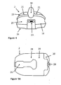
- Figure 4 represents a rear view of the tracker case 2, and it specifically shows the closure 20 as well as the airflow breaking-away edge 16.
- Closure 20 includes an interface 23, in this given example a micro-USB interface, which is in electrical connection to the source of electrical energy and/or the other current carrying components of the track case 2, in particular the receiver means 3 and/or the transmitter means 5.
- the interface 23 the source of electrical energy can be loaded, and the other components can be programmed if required. It is to be understood that also other types of interfaces can be provided to fulfill the aforementioned tasks.
- FIG 5A the base 24 of the tracker 2 is shown from below in its closed state.
- An opening 25 (not shown in this figure) is closed by a lid 26. Opening 25 can receive a holding means (shown in figure 5B ) of a gear (not shown) which is attached to the animate being 1 as it is generally known.
- a fixing means 27 is slideably supported in the housing 14, it being understood that the fixing means 27 is considered as an important part of the invention.
- Fixing means 27 is shown in more detail in figure 5B .
- a section of the base 24 of the tracker case 2 is shown from above while the fixing means 27 fixes the holding means 32 of the aforementioned gear (not shown) which extends through the opening 25.
- the fixing means 27 according to this embodiement is made of spring steel; however, other resilient materials can be chosen without deviation from the scope of the invention.
- the fixing means 27 is comprised of a handle part 28 (which is the part of the fixing means 26 shown in figure 5A ), an elongated slider part 29, two contact sections 30 and a connector 31.
- Slider part 29 consists of two rods which are, on one end, attached to the handle part 28. Said rods are spaced apart to each other, for instance in parallel, and evolve into the contact sections 30 at their respective other ends.
- the contact sections 30 have a smaller distance from each other than the respective rods 29 and fix the holding means 32, according to this example, by spring load and form fit.
- the respective far ends (far from the handle part 28) of the contact sections 30 are connected to each other by the connector 31.
- those portions of the contact section 30 neighbouring the rods 29 and the connector 31 are rounded, which facilitates the movement of the contact sections 30 over the holding means 32.
- the connector 31 is of somewhat elongate shape as can be seen from figure 5B , allowing the fixing means 27 to be slideably moved in the housing 24. According to the present example, when a user moves the handle part 28 to the right according to figure 5B , the contact sections 30 would loose contact to the holding means 32, thus allowing the tracker case 2 to be released from the holding means 32.
- the aforementioned design is specifically advantageous because it allows attaching and de-attaching of the tracker case 2 to the gear in a very short amount of time, e.g. 2 to 3 seconds, and without having to touch the animate being 1 while doing so.
- a magnetic switch (not shown) is arranged within the tracker case 2, as it is generally known in the prior art.
- the monitoring device 6 comprises, as described before, receiver means 10 to receive communication data, for instance from an Iridium network.
- communication data refers to any kind of data that is received by the receiver means 10, be it position data, time data, language data, computer data, or the like.
- data concerning the IMEI number of the satellite modem, latitude, longitude, altitude, speed, date, time, number of spotted GPS satellites, and battery level can be received and sent by means of the receiver means 10.
- the receiver means 10 is also capable of sending data, in particular the aforementioned data, to any other correspondingly adapted receiver.
- monitoring device 6 is generally adapted to receive and send data using satellite technology, GSM technology, radio telemetry and any kind of combination thereof.
- Monitoring device 6 further comprises a location receiver means 11, for instance to receive data from a GPS system.
- a conversion means 12 for converting data to a unified or simplified set of data is provided.
- the aforementioned items can be fixed on a board, for instance an FR4 circuit board.
- a source of electrical energy (not shown) is provided in monitoring device 6.
- a battery and/or rechargeable battery is/are located to provide for electrical energy which is for example consumed by the receiver means 10, the transmitter means 11, the conversion means 12, the display 32, and a light source (not shown) to illuminate the keyboard 33 of the monitoring device 6.
- the source of electrical energy can be a battery, e.g. a lithium polymer battery, or it could be a super/ultra capacitor.
- a heating means not shown.
- additional or alternative means for energy provision such as solar cells or fuel cells, or to charge the battery by means of induction, or piezo elements.
- USB interface can also be used for updating the software in the monitoring device 6, or to pair it with the electrical means in the tracker case 2, e.g. the transmitter means 5.
- the keyboard 33 is comprised of nine different keys forming the silhouette of a falcon. However, this is not mandatory; rather, keyboard 33 can consist of keys which are customary in prior art devices. Furthermore the keyboard 33 can replace or be complemented by a display 32 that is designed as touch screen. It is within the scope of this invention that the animate form of the keys can be represented on said touch screen, allowing operation the apparatus 9 according to the invention.
- transverse position sensor By means of a transverse position sensor (not shown) adaptation of the information presented on the display 32 is possible in accordance with the holding position of the monitoring device 6 by the user.
- further data concerning information with respect to messaging of the data, expected time of receipt of a next message, and information customary to route guidance systems can be received, sent, tracked and presented in accordance with the present invention.
- instructions can be inputted in the monitoring device 6, e.g. instructions to choose an operation language of the apparatus 9 or a specific time zone.
- Monitoring device 6 has an antenna 34, which, according to this embodiement, is a Helix-Hybrid-Satellite antenna adapted to receive and send data using the Iridium and GPS frequencies.
- antenna 34 is a Helix-Hybrid-Satellite antenna adapted to receive and send data using the Iridium and GPS frequencies.
- other types of antennae like Helic-Core antennae, planar antennae, Lambda 1 ⁇ 4 antenna, Lambda 5/8 antenna can be provided.
- Said antennae can be laminated into the housing of the monitoring device 6, or they can be replaceable, fixedly mounted or foil antennae.
- Monitoring device 6 also includes a GPS module which is generally known in prior art for receipt of position data.
- GPS module which is generally known in prior art for receipt of position data.
- other geo position systems like Galileo, or a combination of Galileo and Navstar-GPS can be envisaged.
- a navigation system is included in the apparatus 9 according to the invention.
- an emergency mode i.e. in case of an emergency a user instructs the monitoring device 6 by pushing a button (be it a mechanical key in its housing or a virtual key on the display 32) to send data, which represent an emergency state, via e.g. the Iridium communication network.
- the transmitter 5 in the tracker case 2 can be operated in a transmitting cycle mode, during which relevant data for tracking the animate being, in particular latitude, longitude and altitude of the animate being, its speed, actual time and date and/or the energy level of the energy source of the tracker case, are sent according to a defined cycle, in particular one sending operation particular every 5 to 120 minutes (data sending cycle).
- the data can be received by the monitoring device 6, but also by other communication means (13 in figure 1 ) in order to facilitate search of the animate being 1.
- a falcon can be tracked in Dubai not only by one or several person(s) there, but also by a person in a different country or even continent giving assistance to those individuals who physically want to find the animate being 1.
- outputting a light signal from the light source 22 can take place according to a defined cycle (flashing cycle), which can have, but not necessarily has to have, the same cycle rate as the data sending cycle.
- flashing cycle can be turned off when the user of the apparatus 9 positively knows or estimates that the tracking operation will be finished during day time and under favorable weather conditions.
- the data sending cycle and/or flashing cycle can be turned off when the user of the apparatus 9 knows that the tracked animate being 1 is in proximity to the monitoring device 6, in particular some 400 m to 2,000 m away (hereinafter referred to as "Radius Check Mode 1"). This is in particular the case when the animate being 1 is released and has not yet departed, or the user of the apparatus 9 can see the animate being 1 at the end of a tracking process.
- Mode 2 a transmitting time mode
- relevant data for tracking the animate being 1, in particular latitude, longitude and altitude of the animate being 1, its speed, actual time and date and/or the energy level of the energy source of the tracker case 2 are sent according to a defined transmitting time, in particular one data transmission every full hour, and/or 30 data transmissions during 3 days of operation of the tracker case 2 at a given hour.
- outputting a light signal from the light source 22 can take place according to a defined time mode (flashing time mode), which can have, but not necessarily has to have, the same timing as the transmitting time mode (Mode 1).
- flashing time mode can be turned off when the user of the apparatus 9 positively knows or estimates that the tracking operation will be finished during day time and under favorable weather conditions.
- the transmitting time mode (Mode 1) and/or flashing time mode can be turned off when the user of the apparatus 9 knows that the tracked animate being 1 is in proximity to the monitoring device 6, in particular some 400 m to 2,000 m away (hereinafter referred to as "Radius Check Mode 2"). This is in particular the case when the animate being 1 is released and has not yet departed, or the user of the apparatus 9 can see the animate being 1 at the end of a tracking process.
- tracker case 2 and monitoring device 6 are linked to each other, in particular by means of a USB cable to the USB interface 23 or wireless (e.g. by use of a Bluetooth connection).
- the energy source of the tracker case 2 is loaded (P1).
- energy level information and IMEI (International Mobile Equipment Identity) number information are sent via the USB connection, and further hardware as well as software information is readout (P2).
- tracker 2 is instructed whether the user wants to follow Mode 1 or Mode 2 operation as described above via the USB interface 23, and said instruction is saved in the tracker case according to step S4.
- Mode 1 or Mode 2 the user has to decide whether Radius Check Mode 1 or Radius Check Mode 2 shall be activated, and has to instruct tracker case 2 accordingly (step S5). If either Radius Check Mode 1 or Radius Check Mode 2 is selected, then monitoring device 6 needs to receive and transfer geo position data (GPS data) (cf. P3 in figure 7 ) which are saved in the tracker case 2 (step S6). Following step S6, or If neither Radius Check Mode 1 nor Radius Check Mode 2 was chosen, the tracker case 2can be disconnected from the monitoring device 6 (step S7).
- GPS data geo position data
- step S8 the transmitter means 5 in the tracker case 2 is activated by means of the solenoid switch described above. Feedback on the activation is given to the user by a specific flashing signal of the light source 22 (cf. P4), for example 60 light flashes per minute.
- the following routine is executed (S9) to control the animate being's 1 path (e.g. the flight route of a falcon).
- Mode 1 was selected and programmed (S10), all relevant data are being sent via the transmitter means 5 (e.g. the Iridium network) to the corresponding receiver means 10 of the monitoring device 6 (step S 11) in accordance with the chosen cycle, e.g. every 30 minutes.
- the relevant data include latitude, longitude, altitude and, preferably information on the battery condition (cf. P5). If in addition to this a flashing time mode was selected, the light source 22 outputs light signals accordingly. If in addition to this Radius Check Mode 1 was selected, the aforementioned steps S11 and P5, respectively, start only after the animate being 1 has left the chosen area.
- Mode 1 has not been selected in step S10, but Mode 2 (S12), all relevant data (as described before) are transmitted by the transmitter means 5 of the tracker case 2 (S13) according to the selected plan, e.g. eight data transmission proceedings per day for the next three days (P6). If in addition to this a flashing time mode was selected, the light source 22 outputs light signals accordingly (P6). If in addition to this Radius Check Mode 2 was selected, the aforementioned steps S12 and P6, respectively, start only after the animate being 1 has left the chosen area.
- assessment of the position of the tracker case 2 is made in defined time intervals, e.g. every 10 minutes.
- steps S10 and S12 can only be performed if tracker case 2 has access to both the position system satellites 4 and the data communication satellites 7 (cf. P7).
- the transmitter means 5 can be turned off (S14), e.g. by using the solenoid switch of the tracker means 2 and monitoring device 6 as described above. Turning off operation can be indicated by a light signal, e.g. by flashing of the light source 22 during 6 seconds (P8).
- a track process (TP) to track at least one animate being 1, e.g. falcon is described.
- the monitoring device 6 receives data from the data communication satellites 7, e.g. the Iridium satellites, which are relayed from the tracker case 2 via the data communication satellites 7 and/or the communication means 13. To this end, connection to the Iridium network must be established (P20).
- one out of a number of different animate beings 1 which are registered within the apparatus 9 according to this invention, can be selected (S21) in the monitoring device 6; the selected animate being 1 is the chosen one to be tracked, e.g. a falcon.
- a next step (S22) data associated to the falcon are displayed in the display 32.
- its speed or its current altitude are represented.
- technical data relating to latitude and longitude, battery condition of the tracker case 2, time and date are shown as well as an indication of the direction the falcon is heading for ("course over ground").
- the altitude of the falcon but also of the person tracking the falcon, are of specific interest because, based upon them, it is possible to estimate whether the animal is about to or actually flying for a longer period of time (e.g. difference in altitude of falcon and person is big indicates that the bird is flying high; difference in altitude between falcon and person is small indicates that the falcon does not fly).
- the position of the falcon is shown on a map which is present in the monitoring device 6 (S23).
- position system satellites 4 e.g. Navstar GPS satellites
- P22 position system satellites 4
- the user of the monitoring device 6 requests the GPS system to find a route to the location of the falcon, as it is basically known in prior art. Once this has been achieved, the navigation can stop (S25).
- a track back process (TBP) according to the invention is described.
- current position data e.g. GPS data
- reception of GPS signals is necessary (P30).
- the animate being 1, e.g. a falcon, is flying and found (P31).
- the person having found the falcon wants to return to the place where the tracking process has begun.
- an instruction S31 being navigation to a starting point (or track back as described before), is followed.
- the navigation can be finalized S32, e.g. by turning off the monitoring device 6, and the data related to the starting point can be erased S33.
Landscapes
- Engineering & Computer Science (AREA)
- Life Sciences & Earth Sciences (AREA)
- Radar, Positioning & Navigation (AREA)
- Remote Sensing (AREA)
- Environmental Sciences (AREA)
- Computer Networks & Wireless Communication (AREA)
- Physics & Mathematics (AREA)
- General Physics & Mathematics (AREA)
- Biophysics (AREA)
- Animal Husbandry (AREA)
- Biodiversity & Conservation Biology (AREA)
- Position Fixing By Use Of Radio Waves (AREA)
Abstract
Description
- The present invention concerns an apparatus for tracking an animate being, in particular a bird, and a method for operating such apparatus.
- To men it becomes more and more important to track animate beings. For instance, biologists are interested in learning about wildlife behavior and would like to know about routes migratory animals take during their daily life. On the other hand, farmers having vast estates need to find their dispersed cattle for medical or business reasons. Finally, owners of very precious animate beings, like falcons, want to make sure that they can find their property once it was set free for a limited period of time.
- In order to find and track animate beings, radio-telemetry systems have been developed. A radio-telemetry system consists of a transmitter in a tracker case, which is attached to the animate being, an antenna, in particular a Yagi-Uda antenna, which needs to be held and positioned by the hand of its user, and a monitoring device which is nothing but headphones according to the prior art. The following problems arise with radio-telemetry systems which are applied for tracking an animate being: the antenna is heavy, rendering it very uncomfortable for the user, who additionally has to change his position in order to track the animate being from time to time by foot and/or a vehicle. An additional drawback of this kind of system has to be seen in its inaccuracy with regard to the locating of the transmitter. Furthermore, radio-telemetry systems have a range of about only 25 km, which is little, in particular with respect to falcons which can fly several hundred kilometers per day and therefore easily outrange the antenna. Finally, tracking information is given to the user by sound signals in the headphones which are difficult to interpret and render the tracking process even more inaccurate.
- It is the objective of the present invention to overcome the aforementioned problems.
- To this end, and in one aspect of the invention, an apparatus for tracking an animate being, in particular a bird, comprising a tracker case attachable to the animate being, and a monitoring device, is provided, wherein the tracker case comprises receiver means for receiving position and time data from a number of positioning system satellites, and transmitter means for sending said position and time data to a receiver of the monitoring device by means of data communication satellites.
- According to the invention, the animate being carries a tracker case which includes a receiver adapted to receive data from a number of satellites positioned in orbit and which provide for position and time data. While time data cannot be obtained by means of the radio-telemetry systems of the prior art at all, position data obtained by modern satellite technology are more precise and accurate than those obtainable by means of radio-telemetry systems. According to the invention, position and time data are transmitted by means of a transmitter which is located in the tracker case, and which provides for a reliable sending of the data from the position of the bird by means of data communication satellites to the monitoring device. Use of satellite communication technology according to the invention yields in more reliable communication, i.e. sending information of time and position of the animate being, between the tracker case and the person who tracks the animate being. In addition, by use of satellite communication technology, transmission of data can be assured in territories where other means of communication do not work, e.g. because of mountains or trees which are obstacles for sending radio waves. Finally use of communication satellites makes it possible to track the animate being on any place on earth and by more than one person, such that a team of tracking persons can search for the animate being which can result in its faster discovery.
- In order to provide for a safe and reliable processing of the data in the tracking case, a converter means is in communication with the receiver means and the transmitter means. The converter means converts the position and time data in a format allowing the transmitter means to process the position and time data means.
- The data communication satellites can comprise Iridium satellites which have proven to be reliable and which cover the majority of the world's surface. By this it is possible to track an animate being in regions where data communication is not possible at all.
- The position system satellites comprise at least three Global Position Satellites (GPS). GPS has proven to be reliable and covers the majority of the world's surface. By this it is possible to track an animate being in regions where obtaining position and time data is not possible at all.
- In order to enhance usability of the apparatus according to the invention, the monitoring device can be a hand held device, in particular a personal digital assistant (PDA).
- In order to make it as comfortable for the animate being as possible, the tracker case comprises an aerodynamic housing of light weight material, in particular carbon fibers and/or aramid fibres.
- It may be desirous or even necessary to find an animate being when weather conditions are poor, or during night time. To this end the tracker case according to the invention comprises a light source sending out a light signal which can be seen once a tracking person is comparatively close to the animate being.
- In order to facilitate handling, in particular mounting and fixing of the inventive tracker case to an animate being, thus reducing its stress, a fixing means is provided which is slideable supported on the base of the tracker case and adapted to be in spring-loaded and/or form fit engagement with corresponding holding means attached to the animate being.
- In order to reduce energy consumption during operation of the inventive apparatus, transmission of the position and/or time data can be performed discretely in time and/or in dependency of a defined distance between the animate being and a tracking person.
- Another aspect of the invention refers to the operation of the apparatus, yielding in optimized energy consumption of the electronic components in the tracker case, in particular the receiver means, the transmitter means, the conversion means and/or the light source. In particular, and in a very advantageous manner, operation of the apparatus according to the invention results in a minimization of the energy consumption of the aforementioned items, which allows for a lighter energy source in the tracker case (which in turn results in less load for the animate being to carry), and/or for a longer period of operation of the inventive tracker case. Furthermore, when data are not constantly transmitted, lower costs for transmitting operation, and the use of the apparatus, arise.
- To this end, the apparatus, specifically the tracker case, can be operated in a transmitting cycle mode, during which relevant data for tracking the animate being, in particular latitude, longitude and altitude of the animate being, its speed, actual time and date and/or the energy level of the energy source of the tracker case, are sent according to a defined cycle, in particular one sending operation every 5 to 120 minutes (data sending cycle).
- In addition to this, outputting a light signal from the light source can take place according to a defined cycle (flashing cycle), which can have, but not necessarily has to have, the same cycle rate as the data sending cycle. In particular the flashing cycle can be turned off when the user of the apparatus positively knows or estimates that the tracking operation will be finished during day time and under favorable weather conditions.
- Finally, the data sending cycle and/or flashing cycle can be turned off when the user of the apparatus knows that the tracked animate being is in proximity to the monitoring device, in particular some 400 m to 2,000 m away. This is in particular the case when the animate being is released and has not yet departed, or the user of the apparatus can see the animate being at the end of a tracking process.
- It is also possible to operate the apparatus according to a transmitting time mode, during which relevant data for tracking the animate being, in particular latitude, longitude and altitude of the animate being, its speed, actual time and date and/or the energy level of the energy source of the tracker case, are sent according to a defined transmitting time, in particular one data transmission every full hour, and/or 30 data transmissions during 3 days of operation of the tracker case at a given hour.
- In addition to this, outputting a light signal from the light source can take place according to a defined time mode (flashing time mode), which can have, but not necessarily has to have, the same timing as the transmitting time mode. In particular the flashing time mode can be turned off when the user of the apparatus positively knows or estimates that the tracking operation will be finished during day time and under favorable weather conditions.
- Finally, the transmitting time mode and/or flashing time mode can be turned off when the user of the apparatus knows that the tracked animate being is in proximity to the monitoring device, in particular some 400 m to 2,000 m away. This is in particular the case when the animate being is released and has not yet departed, or the user of the apparatus can see the animate being at the end of a tracking process.
- It shall be noted that a combination of any one of the transmitting cycle mode, flashing mode, transmitting time mode and flashing time mode is possible according to the invention.
- Other objects, features and advantages of the invention will become more apparent from the following non-limiting description of the invention taken in conjunction with the accompanying drawings.
-
-
Figure 1 is a diagrammatic view of the apparatus according to the invention (flashes indicate lines of data transfer/communication in either direction); -
Figure 2 is a perspective view of the tracker case according to the invention; -
Figure 3 is a top view of the tracker case according to the invention; -
Figure 4 is a rear view of the tracker case according to the invention; -
Figure 5A is a bottom view of the tracker case according to the invention; -
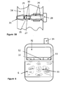
Figure 5B is a detailed view of a fixing means for attaching the tracker case according to the invention to a gear attached to an animate being; -
Figure 6 is a plan view on a monitoring device according to the invention; -
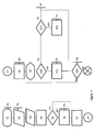
Figure 7 is a description of a first process according to the invention; -
Figure 8 is a description of a second process according to the invention; and -
Figure 9 is a description of a third process according to the invention. - Referring to
figure 1 , an animate being 1 carries atracker case 2. Thetracker case 2 can be positioned on the animate being 1 in a way that latter one cannot manipulate or remove saidtracker case 2, e.g. in case of a bird, in particular a falcon, on its back. - Within the tracker case 2 a receiver means 3 is arranged which receives position and time data from
position system satellites 4, e.g. from at least three Global Position Satellites of the Global Positioning Systems (NAVSTAR GPS). It shall be noted that the position system satellites can be subject to other satellite positioning systems, e.g. Galilieo, Glonass or Compass alike. - It shall be noted that according to the invention in addition to time data, such as date and time (UTC for example), and position data, such as longitude, latitude, and altitude, other data, such as identification numbers (in particular IMEI number of the transmitter means 5), speed over ground of the
tracker case 2, loading status of a power supply (not shown) in thetracker case 2, number of retrieved GPS satellites etc. can be retrieved and exchanged between the receiver means 3, the conversion means 8, the transmitter means 5 and themonitoring device 6. - Within the tracker case 2 a transmitter means 5 is provided for sending position and time data to a
monitoring device 6 viadata communication satellites 7. Thedata communication satellites 7 can belong to the Iridium satellite network, or any other satellite communication network such as Thuraya or Inmarsat. It shall be noted that, according to the invention, the transmitter means 5 can not only send data to themonitoring device 6, but it can also receive data from themonitoring device 6 via thedata communication satellites 7. By this it is possible to send instruction data, i.e. data to manipulate theapparatus 9, in particular to thetracker case 2. - In order to allow or facilitate transfer of position and time data from the receiver means 3 to the transmitter means 5 a conversion means 8 can be provided. The conversion means 8 can comprise a corresponding micro processor (not shown).
- According to the invention the
monitoring device 6 is a hand held device, e.g. a personal digital assistant (PDA), a smartphone or a laptop computer. However, it shall be noted that instead of, or in addition to, thehandheld device 6 any other communication device can be used. For instance it can be provided that a person tracking a bird, in particular a falcon, uses a PDA, while another person can follow data and communication exchange as described before in parallel, or with time delay, by means of a computer system via Internet. Themonitoring device 6 includes a World Base Map allowing for easy understanding of the user where the animate being 1 to be tracked can be found. - According to the present example of the invention the following procedure of data and communication exchange is followed: position and time data (at least) are received by the receiver means 3 in the
tracker case 2 by theGPS satellites 4 orbiting in an altitude of about 20,200 km. These data are processed in the converter means 8 and input into the transmitter means 5 which can be an Iridium satellite modem. The aforementioned data are sent by means of the transmitter means 5 to the Iridium satellites (orbiting in an altitude of some 760 km) and relay network (data communication satellites 7). These data are then sent from the Iridium satellite andrelay network 7 to themonitoring device 6 which comprises, as is generally known, receiver means for receiving data from both Iridium satellites (Iridium receiver means 10) as well as the GPS satellites 4 (GPS receiver means 11). For an exchange of data between the Iridium receiver means 10 and the GPS receiver means 11, a converter means 12 can be provided in themonitoring device 6. Data sent and received by means of the Iridium satellite system can also be received and manipulated by means of further, additional communication means 13 such as cell phones, computers connected to the Internet. By following the above procedure in reverse direction data can be transmitted from themonitoring device 6 to thetracker case 2. - Without deviation from the scope of protection of the present invention the
tracker case 2 may also include further communication means (not shown) allowing for e.g. GSM services. - Referring now to
figure 2 , thetracker case 2 is shown. Thetracker case 2 has anaerodynamic housing 14 of light weight material, such as carbon fibres and/or glass fibres and/or aramid fibres, which can be manufactured by lamination or moulding techniques. This material selection allows use of theapparatus 9 according to the invention also in harsh conditions. For instance, theinventive tracker case 2 can be applied with falcons, which fly up to 320 km/h and in very high altitudes, without breaking. When attached to the body of the falcon,section 15 represents the leading edge of thetracker case 2 in the direction of flight. Furthermore, and in accordance with the invention, thehousing 14 can comprise an airflow break-awayedge 16 to further minimize aerodynamic drag of thetracker case 2. - An
antenna 17 is provided for assuring communication of the receiver means 3 with theposition system satellites 4 and thedata communication satellites 7. It is to be noted that theantenna 17 reaches through thehousing 14 as it is connected to a circuit board (not shown) on which the receiver means 3, the conversion means 8 and the transmitter means 5 can be located. To avoid any difficulties due to the electrostatic properties of the chosen materials (in particular when using carbon fibers as material for the housing 14), and in accordance with the invention, asection 18 of thehousing 14 neighbouring the area where theantenna 17 exits thehousing 14 can be made of an insulator material, such as aramid fibres.Section 18 is designed as a fin which reduces air resistance. However, this is not mandatory, andsection 18 can be designed in any other suitable form and even form a smooth surface with rest of thehousing 14. -
Antenna 17 can be a 5/8 Lambda antenna made of spring steel assuring receipt and sending of data on GPS level (1575 MHz) and Iridium levels (1616 to 1626 MHz). However, it is to be understood that other types of antennae, like helix antenna, helix-core-antenna, planar antenna, Lambda ¼-antenna or the like can be used. Theantenna 17 can be arranged as shown infigure 2 , or it can be laminated in thehousing 14, or arranged as foil antenna. - In
figure 3 the leadingedge 15, the airflow break-awayedge 16, and thesection 18 of thehousing 14 can be seen, whereas the antenna has been omitted in said figure for the sake of simplicity. In this embodiement of the invention,housing 14 comprises two parts, one forming the major part of areceptacle 19, and another one forming aclosure 20. While in this emodiement the receptacle comprises the leadingedge 15,closure 20 comprises the airflow break-awayedge 16. As can readily be seen,receptacle 19 andclosure 20 form integral parts of thehousing 14 when theclosure 20 is fixed to thereceptacle 19. Fixation can be assured by any known means, in particular by form fit, positive fit or the like. - As can be seen in
figure 2 and figure 3 , the outer shape of thehousing 14 comprises rounded edges, in particular rounded upper sideedges forming shoulders 21 extending lengthwise over the upper part of thereceptacle 19. This further enhances the aerodynamic properties of thetracker case 2. - Since the animate being 1 carrying the
tracker case 2 must be able to be found also under bad weather conditions or during night time,tracker case 2 can be provided with alight source 22 which optically signals the position of the animate being 1 to a tracking person. In the embodiement of the invention represented infigures 2 and 3 , thelight source 22 comprises four light emitting diodes (LED), which are arranged in couples of two and lengthwise along therespective shoulders 21 of thereceptacle 19 in parallel to the fin likesection 18. This arrangement is specifically advantageous because the light is emitted by the LEDs in a nearly spherical direction making it easier to be seen by a tracking person. Each LED can have a luminous intensity of 40,000 cd for example, allowing for good visibility of the tracker case for at least 2,000 meters. Thelight source 22 is connected to a processor (not shown) in thetracker case 2. The processor itself is in connection to the transmitter means 5, allowing to be programmed by the user such that thelight source 22 is emitting light permanently or discretely by flashing. For instance, according to the invention it is possible to provide for thelight source 22 to only emit light depending on some specific time related information, as received by theposition system satellites 4. For instance it is possible to program the processor such that thelight source 22 only emits light by flashing every 30 seconds for a second after five o'clock in the afternoon. - Furthermore it is possible that the
light source 22 according to the invention can signal information on its operational state, e.g. in order to indicate that the transmitter means 5 is being activated or deactivated, that the receiver means does not receive any information of theposition system satellites 4, or the like. - It can be readily understood that the
tracker case 2 requires a source of electrical energy (not shown). For instance, a battery and/or rechargeable battery is/are located in thetracker case 2 to provide for electrical energy which is for example consumed by the receiver means 3, the transmitter means 5, the conversion means 8, and thelight source 22. The battery can be a lithium polymer battery, or it could be a super/ultra capacitor. In order to increase functioning of the battery, it is also possible to heat the battery by means of a heating means (not shown). It is also possible to provide additional or alternative means for energy provision, such as solar cells or fuel cells, or to charge the battery by means of induction or piezo elements. -
Figure 4 represents a rear view of thetracker case 2, and it specifically shows theclosure 20 as well as the airflow breaking-away edge 16.Closure 20 includes aninterface 23, in this given example a micro-USB interface, which is in electrical connection to the source of electrical energy and/or the other current carrying components of thetrack case 2, in particular the receiver means 3 and/or the transmitter means 5. By means of theinterface 23, the source of electrical energy can be loaded, and the other components can be programmed if required. It is to be understood that also other types of interfaces can be provided to fulfill the aforementioned tasks. - Referring now to
figure 5A , thebase 24 of thetracker 2 is shown from below in its closed state. An opening 25 (not shown in this figure) is closed by alid 26.Opening 25 can receive a holding means (shown infigure 5B ) of a gear (not shown) which is attached to the animate being 1 as it is generally known. A fixing means 27 is slideably supported in thehousing 14, it being understood that the fixing means 27 is considered as an important part of the invention. - Fixing means 27 is shown in more detail in
figure 5B . A section of thebase 24 of thetracker case 2 is shown from above while the fixing means 27 fixes the holding means 32 of the aforementioned gear (not shown) which extends through theopening 25. The fixing means 27 according to this embodiement is made of spring steel; however, other resilient materials can be chosen without deviation from the scope of the invention. The fixing means 27 is comprised of a handle part 28 (which is the part of the fixing means 26 shown infigure 5A ), anelongated slider part 29, twocontact sections 30 and aconnector 31. -
Slider part 29 consists of two rods which are, on one end, attached to thehandle part 28. Said rods are spaced apart to each other, for instance in parallel, and evolve into thecontact sections 30 at their respective other ends. Thecontact sections 30 have a smaller distance from each other than therespective rods 29 and fix the holding means 32, according to this example, by spring load and form fit. The respective far ends (far from the handle part 28) of thecontact sections 30 are connected to each other by theconnector 31. As can readably be seen infigure 5B , those portions of thecontact section 30 neighbouring therods 29 and theconnector 31 are rounded, which facilitates the movement of thecontact sections 30 over the holding means 32. - The
connector 31 is of somewhat elongate shape as can be seen fromfigure 5B , allowing the fixing means 27 to be slideably moved in thehousing 24. According to the present example, when a user moves thehandle part 28 to the right according tofigure 5B , thecontact sections 30 would loose contact to the holding means 32, thus allowing thetracker case 2 to be released from the holding means 32. - The aforementioned design is specifically advantageous because it allows attaching and de-attaching of the
tracker case 2 to the gear in a very short amount of time, e.g. 2 to 3 seconds, and without having to touch the animate being 1 while doing so. - In order to activate or de-activate anyone or all of
means tracker case 2, as it is generally known in the prior art. - Said magnetic switch is activated by a corresponding activation element (not shown) in the
monitoring device 6, which is explained now more in detail with reference tofigure 6 . Themonitoring device 6 comprises, as described before, receiver means 10 to receive communication data, for instance from an Iridium network. It shall be understood that communication data refers to any kind of data that is received by the receiver means 10, be it position data, time data, language data, computer data, or the like. For instance, data concerning the IMEI number of the satellite modem, latitude, longitude, altitude, speed, date, time, number of spotted GPS satellites, and battery level, can be received and sent by means of the receiver means 10. It shall be understood that, while the term receiver means 10 is used, the receiver means 10 is also capable of sending data, in particular the aforementioned data, to any other correspondingly adapted receiver. - It shall be understood that
monitoring device 6 is generally adapted to receive and send data using satellite technology, GSM technology, radio telemetry and any kind of combination thereof. -
Monitoring device 6 further comprises a location receiver means 11, for instance to receive data from a GPS system. In order to allow communication and exchange of data within themonitoring device 6, a conversion means 12 for converting data to a unified or simplified set of data is provided. The aforementioned items can be fixed on a board, for instance an FR4 circuit board. - A source of electrical energy (not shown) is provided in
monitoring device 6. For instance, a battery and/or rechargeable battery is/are located to provide for electrical energy which is for example consumed by the receiver means 10, the transmitter means 11, the conversion means 12, thedisplay 32, and a light source (not shown) to illuminate thekeyboard 33 of themonitoring device 6. The source of electrical energy can be a battery, e.g. a lithium polymer battery, or it could be a super/ultra capacitor. In order to increase functioning of the battery, it is also possible to heat the battery by means of a heating means (not shown). It is also possible to provide additional or alternative means for energy provision, such as solar cells or fuel cells, or to charge the battery by means of induction, or piezo elements. Finally it is possible to load the battery within themonitoring device 6 by connecting it to a power supply outside saiddevice 6, e.g. by means of a USB cable to a USB interface (not shown), as is generally known. For the sake of completeness it shall be mentioned that the USB interface can also be used for updating the software in themonitoring device 6, or to pair it with the electrical means in thetracker case 2, e.g. the transmitter means 5. - As can be seen in
figure 6 , thekeyboard 33 is comprised of nine different keys forming the silhouette of a falcon. However, this is not mandatory; rather,keyboard 33 can consist of keys which are customary in prior art devices. Furthermore thekeyboard 33 can replace or be complemented by adisplay 32 that is designed as touch screen. It is within the scope of this invention that the animate form of the keys can be represented on said touch screen, allowing operation theapparatus 9 according to the invention. - By means of a transverse position sensor (not shown) adaptation of the information presented on the
display 32 is possible in accordance with the holding position of themonitoring device 6 by the user. Despite the data mentioned before, further data concerning information with respect to messaging of the data, expected time of receipt of a next message, and information customary to route guidance systems can be received, sent, tracked and presented in accordance with the present invention. Furthermore, instructions can be inputted in themonitoring device 6, e.g. instructions to choose an operation language of theapparatus 9 or a specific time zone. -
Monitoring device 6 has anantenna 34, which, according to this embodiement, is a Helix-Hybrid-Satellite antenna adapted to receive and send data using the Iridium and GPS frequencies. However, it shall be understood that also other types of antennae, like Helic-Core antennae, planar antennae, Lambda ¼ antenna,Lambda 5/8 antenna can be provided. Said antennae can be laminated into the housing of themonitoring device 6, or they can be replaceable, fixedly mounted or foil antennae. -
Monitoring device 6 also includes a GPS module which is generally known in prior art for receipt of position data. However, according to the invention other geo position systems, like Galileo, or a combination of Galileo and Navstar-GPS can be envisaged. - According to the invention, it is possible to track not only one animate being 1 by means of the
apparatus 9, but to track several, in particular three,animate beings 1 at the same time. - According to the invention it is possible to find the way from a place where the animate being 1 has been tracked and found (find spot) back to the start location where the tracking process has started by storing the geo data of the start location, comparing the geo data of the start location with the geo data of the find spot, and calculating a path from the find spot to the start location as it is generally known in the prior art. To this end, a navigation system is included in the
apparatus 9 according to the invention. - According to the invention it is also possible to provide for an emergency mode, i.e. in case of an emergency a user instructs the
monitoring device 6 by pushing a button (be it a mechanical key in its housing or a virtual key on the display 32) to send data, which represent an emergency state, via e.g. the Iridium communication network. - It shall be understood that, while unidirectional data transfer via the Navstar GPS has been described before, also bidirectional data transfer via the Navstar GPS network is part of the invention.
- In order to make operation of the
apparatus 9 according to the invention more transparent, different operation modes are described. - In the first operation mode (hereinafter referred to as "
Mode 1") thetransmitter 5 in thetracker case 2 can be operated in a transmitting cycle mode, during which relevant data for tracking the animate being, in particular latitude, longitude and altitude of the animate being, its speed, actual time and date and/or the energy level of the energy source of the tracker case, are sent according to a defined cycle, in particular one sending operation particular every 5 to 120 minutes (data sending cycle). - According to the invention the data can be received by the
monitoring device 6, but also by other communication means (13 infigure 1 ) in order to facilitate search of the animate being 1. For instance, a falcon can be tracked in Dubai not only by one or several person(s) there, but also by a person in a different country or even continent giving assistance to those individuals who physically want to find the animate being 1. - In addition to this, outputting a light signal from the
light source 22 can take place according to a defined cycle (flashing cycle), which can have, but not necessarily has to have, the same cycle rate as the data sending cycle. In particular the flashing cycle can be turned off when the user of theapparatus 9 positively knows or estimates that the tracking operation will be finished during day time and under favorable weather conditions. - Finally, the data sending cycle and/or flashing cycle can be turned off when the user of the
apparatus 9 knows that the tracked animate being 1 is in proximity to themonitoring device 6, in particular some 400 m to 2,000 m away (hereinafter referred to as "Radius Check Mode 1"). This is in particular the case when the animate being 1 is released and has not yet departed, or the user of theapparatus 9 can see the animate being 1 at the end of a tracking process. - It is also possible to operate the
apparatus 9 according to a transmitting time mode (hereinafter referred to "Mode 2"), during which relevant data for tracking the animate being 1, in particular latitude, longitude and altitude of the animate being 1, its speed, actual time and date and/or the energy level of the energy source of thetracker case 2, are sent according to a defined transmitting time, in particular one data transmission every full hour, and/or 30 data transmissions during 3 days of operation of thetracker case 2 at a given hour. - In addition to this, outputting a light signal from the
light source 22 can take place according to a defined time mode (flashing time mode), which can have, but not necessarily has to have, the same timing as the transmitting time mode (Mode 1). In particular the flashing time mode can be turned off when the user of theapparatus 9 positively knows or estimates that the tracking operation will be finished during day time and under favorable weather conditions. - Finally, the transmitting time mode (Mode 1) and/or flashing time mode can be turned off when the user of the
apparatus 9 knows that the tracked animate being 1 is in proximity to themonitoring device 6, in particular some 400 m to 2,000 m away (hereinafter referred to as "Radius Check Mode 2"). This is in particular the case when the animate being 1 is released and has not yet departed, or the user of theapparatus 9 can see the animate being 1 at the end of a tracking process. - It shall be noted that a combination of any one of the transmitting cycle mode, flashing mode, transmitting time mode and flashing time mode is possible.
- An exemplary process of operation of the invention is now accordingly described in detail (cf.
figure 7 ): - In a first step
S1 tracker case 2 andmonitoring device 6 are linked to each other, in particular by means of a USB cable to theUSB interface 23 or wireless (e.g. by use of a Bluetooth connection). The energy source of thetracker case 2 is loaded (P1). In a next step S2, energy level information and IMEI (International Mobile Equipment Identity) number information are sent via the USB connection, and further hardware as well as software information is readout (P2). In a next step S3,tracker 2 is instructed whether the user wants to followMode 1 orMode 2 operation as described above via theUSB interface 23, and said instruction is saved in the tracker case according to step S4. Next, if eitherMode 1 orMode 2 is chosen, the user has to decide whetherRadius Check Mode 1 orRadius Check Mode 2 shall be activated, and has to instructtracker case 2 accordingly (step S5). If eitherRadius Check Mode 1 orRadius Check Mode 2 is selected, then monitoringdevice 6 needs to receive and transfer geo position data (GPS data) (cf. P3 infigure 7 ) which are saved in the tracker case 2 (step S6). Following step S6, or If neitherRadius Check Mode 1 norRadius Check Mode 2 was chosen, the tracker case 2can be disconnected from the monitoring device 6 (step S7). - In a next step S8 the transmitter means 5 in the
tracker case 2 is activated by means of the solenoid switch described above. Feedback on the activation is given to the user by a specific flashing signal of the light source 22 (cf. P4), for example 60 light flashes per minute. - Once the
tracker case 2 is activated and attached to the animate being 1, the following routine is executed (S9) to control the animate being's 1 path (e.g. the flight route of a falcon). - If
Mode 1 was selected and programmed (S10), all relevant data are being sent via the transmitter means 5 (e.g. the Iridium network) to the corresponding receiver means 10 of the monitoring device 6 (step S 11) in accordance with the chosen cycle, e.g. every 30 minutes. The relevant data include latitude, longitude, altitude and, preferably information on the battery condition (cf. P5). If in addition to this a flashing time mode was selected, thelight source 22 outputs light signals accordingly. If in addition to thisRadius Check Mode 1 was selected, the aforementioned steps S11 and P5, respectively, start only after the animate being 1 has left the chosen area. - If
Mode 1 has not been selected in step S10, but Mode 2 (S12), all relevant data (as described before) are transmitted by the transmitter means 5 of the tracker case 2 (S13) according to the selected plan, e.g. eight data transmission proceedings per day for the next three days (P6). If in addition to this a flashing time mode was selected, thelight source 22 outputs light signals accordingly (P6). If in addition to thisRadius Check Mode 2 was selected, the aforementioned steps S12 and P6, respectively, start only after the animate being 1 has left the chosen area. - In any event, according to P5 and P6, assessment of the position of the
tracker case 2 is made in defined time intervals, e.g. every 10 minutes. - As can be readily understood, steps S10 and S12 can only be performed if
tracker case 2 has access to both theposition system satellites 4 and the data communication satellites 7 (cf. P7). - If the animate being 1 is found, the transmitter means 5 can be turned off (S14), e.g. by using the solenoid switch of the tracker means 2 and
monitoring device 6 as described above. Turning off operation can be indicated by a light signal, e.g. by flashing of thelight source 22 during 6 seconds (P8). - In
figure 8 , a track process (TP) to track at least one animate being 1, e.g. falcon, is described. In a first step S20, themonitoring device 6 receives data from thedata communication satellites 7, e.g. the Iridium satellites, which are relayed from thetracker case 2 via thedata communication satellites 7 and/or the communication means 13. To this end, connection to the Iridium network must be established (P20). Next, one out of a number of differentanimate beings 1 which are registered within theapparatus 9 according to this invention, can be selected (S21) in themonitoring device 6; the selected animate being 1 is the chosen one to be tracked, e.g. a falcon. In a next step (S22), data associated to the falcon are displayed in thedisplay 32. In particular, and as can be seen from P21, its speed or its current altitude are represented. Furthermore, technical data relating to latitude and longitude, battery condition of thetracker case 2, time and date are shown as well as an indication of the direction the falcon is heading for ("course over ground"). - It shall be noted that the altitude of the falcon, but also of the person tracking the falcon, are of specific interest because, based upon them, it is possible to estimate whether the animal is about to or actually flying for a longer period of time (e.g. difference in altitude of falcon and person is big indicates that the bird is flying high; difference in altitude between falcon and person is small indicates that the falcon does not fly).
- Once these data are received by the
monitoring device 6, the position of the falcon is shown on a map which is present in the monitoring device 6 (S23). In a next step S24, and having established connection to position system satellites 4 (e.g. Navstar GPS satellites) (P22), the user of themonitoring device 6 requests the GPS system to find a route to the location of the falcon, as it is basically known in prior art. Once this has been achieved, the navigation can stop (S25). - In
figure 9 a track back process (TBP) according to the invention is described. In a first step S30, current position data, e.g. GPS data, are saved. To this end, reception of GPS signals is necessary (P30). The animate being 1, e.g. a falcon, is flying and found (P31). Next, the person having found the falcon wants to return to the place where the tracking process has begun. To this end, an instruction S31, being navigation to a starting point (or track back as described before), is followed. Once this has been achieved, i.e. the person having found the animate being 1 has returned to the starting location of the tracking process, the navigation can be finalized S32, e.g. by turning off themonitoring device 6, and the data related to the starting point can be erased S33. - While selected features of the invention were described above in detail, it shall be understood that any or all of the features, or any or all combinations thereof, which have not been described or claimed in detail, is to be considered as part of the invention and its disclosure. This is particularly true for the
tracker case 2 and its associated feature according to this application text, which is to be considered an invention in itself.LIST OF REFERENCE NUMBERS 1 Animate being 2 Tracker case 3 Receiver means 4 Position system satellites 5 Transmitter means 6 Monitoring device 7 Data communication satellites 8 Conversion means 9 Apparatus 10 Iridium receiver means 11 GPS receiver means 12 Converter means 13 Communication means 14 Housing 15 Leading edge 16 Airflow break-away edge 17 Antenna 18 Section 19 Receptacle 20 Closure 21 Shoulders 22 Light source 23 Interface 24 Base of the tracker case 25 Opening 26 Lid 27 Fixing means 28 Handle part 29 Rods 30 Contact sections 31 Connector 32 Display 33 Keyboard 34 Antenna 35 Holding means
Claims (14)
- Apparatus (9) for tracking an animate being (1), in particular a bird, comprising a tracker case (2) attachable to the animate being, and a monitoring device (6), characterized in that the tracker case (2) comprises receiver means (3) for receiving position and time data from a number of positioning system satellites (4), and transmitter means (5) for sending said position and time data to a receiver (10) of the monitoring device (2) by means of data communication satellites (7).
- Apparatus (9) according to claim 2, characterized by converter means (8) in communication with the receiver means (3) and transmitter means (5) in order to convert the position and time data in a format allowing the transmitter means (5) to process the position and time data.
- Apparatus (9) according to claim 1 or 2, characterized in that the data communication satellites (7) are Iridium satellites.
- Apparatus (9) according to any of the preceding claims, characterized in that the position system satellites (4) comprise at least three Global Position Satellites.
- Apparatus (9) according to any of the preceding claims, characterized in that the monitoring device (6) is a hand held device.
- Apparatus (9) according to any of the preceding claims, characterized in that the tracker case (2) comprises an aerodynamic housing (14) of light weight material.
- Apparatus (9) according to any of the preceding claims, characterized in that the tracker case (2) comprises a light source (22).
- Apparatus (9) according to any of the preceding claims, characterized in that the tracker case (2) comprises a fixing means (27) which is slideably supported on the base (24) of the tracker case (2) and adapted to be in spring-loaded and/or form fit engagement with a corresponding holding means (35) attached to the animate being (1).
- Method of operation of an apparatus (9) according to any of the preceding claims, characterized in that transmission of the position and/or time data is performed discretely in time and/or in dependency of a defined distance between the animate being (1) and a tracking person.
- Method according to claim 9, characterized in that tracking data are transmitted by the transmitter means (5) based upon a defined time dependent cycle.
- Method according to claim 9 or 10, characterized in that outputting a light signal from the light source (22) is output according to a defined time dependent cycle.
- Method according to any of the claims 9 to 11, characterized in that tracking data are transmitted by the transmitter means (5) according to a defined transmitting time.
- Method according to any of the claims 9 to 11, characterized in that a light signal from the light source (5) is output according to a defined output time mode.
- Method according to any of the claims 9 to 13, characterized in that transmission of tracking data and/or outputting a light signal takes place once the tracker case (2) is located beyond a defined periphery around the monitoring device (6).
Priority Applications (1)
| Application Number | Priority Date | Filing Date | Title |
|---|---|---|---|
| EP13001667.8A EP2784545B1 (en) | 2013-03-30 | 2013-03-30 | Apparatus for tracking an animate being, in particular a bird, and operation of such apparatus |
Applications Claiming Priority (1)
| Application Number | Priority Date | Filing Date | Title |
|---|---|---|---|
| EP13001667.8A EP2784545B1 (en) | 2013-03-30 | 2013-03-30 | Apparatus for tracking an animate being, in particular a bird, and operation of such apparatus |
Publications (2)
| Publication Number | Publication Date |
|---|---|
| EP2784545A1 true EP2784545A1 (en) | 2014-10-01 |
| EP2784545B1 EP2784545B1 (en) | 2016-09-14 |
Family
ID=48049746
Family Applications (1)
| Application Number | Title | Priority Date | Filing Date |
|---|---|---|---|
| EP13001667.8A Not-in-force EP2784545B1 (en) | 2013-03-30 | 2013-03-30 | Apparatus for tracking an animate being, in particular a bird, and operation of such apparatus |
Country Status (1)
| Country | Link |
|---|---|
| EP (1) | EP2784545B1 (en) |
Cited By (4)
| Publication number | Priority date | Publication date | Assignee | Title |
|---|---|---|---|---|
| CN107006395A (en) * | 2016-10-10 | 2017-08-04 | 湖南环球信士科技有限公司 | Biological follow-up mechanism and system |
| CN108617545A (en) * | 2018-01-26 | 2018-10-09 | 湖南环球信士科技有限公司 | A kind of birds tracker |
| ES2735650A1 (en) * | 2019-01-31 | 2019-12-19 | Albert Damaso Nacher | Bird tracking and locator system (Machine-translation by Google Translate, not legally binding) |
| US20240407340A1 (en) * | 2023-06-12 | 2024-12-12 | Marshall Radio Telemetry, Inc. | Tracking systems with standard transmitters and tailored carriers |
Families Citing this family (1)
| Publication number | Priority date | Publication date | Assignee | Title |
|---|---|---|---|---|
| CN108632526B (en) * | 2018-02-01 | 2020-06-23 | 湖南环球信士科技有限公司 | Bird tracking system |
Citations (5)
| Publication number | Priority date | Publication date | Assignee | Title |
|---|---|---|---|---|
| US20050136912A1 (en) * | 1999-03-31 | 2005-06-23 | Curatolo Benedict S. | Security and tracking system |
| US20080001815A1 (en) * | 2006-06-29 | 2008-01-03 | Bily Wang | Micro-tracking device for tracing action track of animals and method for using the same |
| US20090002188A1 (en) * | 2005-03-09 | 2009-01-01 | Stephen Jay Greenberg | Tracking System and Portable Virtual Fence |
| EP2063285A1 (en) * | 2007-11-13 | 2009-05-27 | Gantner Pigeon Systems GmbH | Method for the implementation of pigeon races in pigeon sport and a location system to implement the method |
| US20120206296A1 (en) * | 2011-02-16 | 2012-08-16 | Wan Lawrence A | Self-charging power controlled system for locating animals by gps |
Family Cites Families (2)
| Publication number | Priority date | Publication date | Assignee | Title |
|---|---|---|---|---|
| US20070266959A1 (en) * | 2006-05-17 | 2007-11-22 | Brooks Tom J | Method and apparatus for monitoring an animal in real time |
| FR2961605B1 (en) * | 2010-06-18 | 2013-07-19 | Univ Sud Toulon Var | SATELLITE BEACON FOR WHALING FOLLOWING |
-
2013
- 2013-03-30 EP EP13001667.8A patent/EP2784545B1/en not_active Not-in-force
Patent Citations (5)
| Publication number | Priority date | Publication date | Assignee | Title |
|---|---|---|---|---|
| US20050136912A1 (en) * | 1999-03-31 | 2005-06-23 | Curatolo Benedict S. | Security and tracking system |
| US20090002188A1 (en) * | 2005-03-09 | 2009-01-01 | Stephen Jay Greenberg | Tracking System and Portable Virtual Fence |
| US20080001815A1 (en) * | 2006-06-29 | 2008-01-03 | Bily Wang | Micro-tracking device for tracing action track of animals and method for using the same |
| EP2063285A1 (en) * | 2007-11-13 | 2009-05-27 | Gantner Pigeon Systems GmbH | Method for the implementation of pigeon races in pigeon sport and a location system to implement the method |
| US20120206296A1 (en) * | 2011-02-16 | 2012-08-16 | Wan Lawrence A | Self-charging power controlled system for locating animals by gps |
Cited By (4)
| Publication number | Priority date | Publication date | Assignee | Title |
|---|---|---|---|---|
| CN107006395A (en) * | 2016-10-10 | 2017-08-04 | 湖南环球信士科技有限公司 | Biological follow-up mechanism and system |
| CN108617545A (en) * | 2018-01-26 | 2018-10-09 | 湖南环球信士科技有限公司 | A kind of birds tracker |
| ES2735650A1 (en) * | 2019-01-31 | 2019-12-19 | Albert Damaso Nacher | Bird tracking and locator system (Machine-translation by Google Translate, not legally binding) |
| US20240407340A1 (en) * | 2023-06-12 | 2024-12-12 | Marshall Radio Telemetry, Inc. | Tracking systems with standard transmitters and tailored carriers |
Also Published As
| Publication number | Publication date |
|---|---|
| EP2784545B1 (en) | 2016-09-14 |
Similar Documents
| Publication | Publication Date | Title |
|---|---|---|
| EP2956789B1 (en) | Animal tracking apparatus | |
| US20230005349A1 (en) | System for Location in Environment and Identification Tag | |
| US7602302B2 (en) | Animal tracking apparatus and method | |
| EP2784545B1 (en) | Apparatus for tracking an animate being, in particular a bird, and operation of such apparatus | |
| US7847727B2 (en) | Object identity and location tracking system | |
| Mech | Handbook of animal radio-tracking | |
| Rodgers et al. | A GPS-based telemetry system | |
| CN105139180B (en) | A kind of unmanned plane transport roof communication base station | |
| WO2007031782A1 (en) | Device for indicating direction to predetermined location | |
| Someswar et al. | Global navigation satellite systems and their applications | |
| CN101097252B (en) | Portable electronic device having save electricity function and electricity saving method | |
| RU168042U1 (en) | Remote-controlled automated soil sampler | |
| Si et al. | Position data acquisition from NMEA protocol of global positioning system | |
| Collins et al. | Uas lidar mapping of an arctic tundra watershed: Challenges and opportunities | |
| CN101487885B (en) | GPS locator for tracing and training | |
| Senanayake | Anticipated prospects and civilian applications of Indian satellite navigation services in Sri Lanka | |
| CN101131423B (en) | Global positioning tracker and its tracking method | |
| Strydom | Integrating Satellite-Tracking in Wildlife Conservation: A Review and Proposal | |
| AU2008207406A1 (en) | Pet tracking system utilizing the global-positioning system | |
| CN201314950Y (en) | GPS (global positioning system) tracker | |
| Planck | Observing and Analyzing Arctic Sea Ice Mass Balance Using Autonomous Systems | |
| ES2255401B1 (en) | NON-SUPERVISED POSITIONING AND CONTROL SYSTEM OF LIVESTOCK BASED ON GNSS TECHNOLOGIES. | |
| Subbaraya | Development of Lagrangian Drifter for Ocean Monitoring and Marine Applications | |
| Schneider et al. | INTERACT Fieldwork Communication and Navigation. | |
| Saputra et al. | Performance analysis of a multi-purpose winch integrated with the UAV Phantom 3 type for marine conservation and survey applications |
Legal Events
| Date | Code | Title | Description |
|---|---|---|---|
| 17P | Request for examination filed |
Effective date: 20130423 |
|
| AK | Designated contracting states |
Kind code of ref document: A1 Designated state(s): AL AT BE BG CH CY CZ DE DK EE ES FI FR GB GR HR HU IE IS IT LI LT LU LV MC MK MT NL NO PL PT RO RS SE SI SK SM TR |
|
| AX | Request for extension of the european patent |
Extension state: BA ME |
|
| PUAI | Public reference made under article 153(3) epc to a published international application that has entered the european phase |
Free format text: ORIGINAL CODE: 0009012 |
|
| 17Q | First examination report despatched |
Effective date: 20150128 |
|
| GRAP | Despatch of communication of intention to grant a patent |
Free format text: ORIGINAL CODE: EPIDOSNIGR1 |
|
| INTG | Intention to grant announced |
Effective date: 20160324 |
|
| GRAS | Grant fee paid |
Free format text: ORIGINAL CODE: EPIDOSNIGR3 |
|
| GRAA | (expected) grant |
Free format text: ORIGINAL CODE: 0009210 |
|
| AK | Designated contracting states |
Kind code of ref document: B1 Designated state(s): AL AT BE BG CH CY CZ DE DK EE ES FI FR GB GR HR HU IE IS IT LI LT LU LV MC MK MT NL NO PL PT RO RS SE SI SK SM TR |
|
| REG | Reference to a national code |
Ref country code: GB Ref legal event code: FG4D |
|
| REG | Reference to a national code |
Ref country code: CH Ref legal event code: EP |
|
| REG | Reference to a national code |
Ref country code: IE Ref legal event code: FG4D |
|
| REG | Reference to a national code |
Ref country code: AT Ref legal event code: REF Ref document number: 829599 Country of ref document: AT Kind code of ref document: T Effective date: 20161015 |
|
| REG | Reference to a national code |
Ref country code: DE Ref legal event code: R096 Ref document number: 602013011291 Country of ref document: DE |
|
| REG | Reference to a national code |
Ref country code: LT Ref legal event code: MG4D |
|
| REG | Reference to a national code |
Ref country code: NL Ref legal event code: MP Effective date: 20160914 |
|
| PG25 | Lapsed in a contracting state [announced via postgrant information from national office to epo] |
Ref country code: LT Free format text: LAPSE BECAUSE OF FAILURE TO SUBMIT A TRANSLATION OF THE DESCRIPTION OR TO PAY THE FEE WITHIN THE PRESCRIBED TIME-LIMIT Effective date: 20160914 Ref country code: NO Free format text: LAPSE BECAUSE OF FAILURE TO SUBMIT A TRANSLATION OF THE DESCRIPTION OR TO PAY THE FEE WITHIN THE PRESCRIBED TIME-LIMIT Effective date: 20161214 Ref country code: HR Free format text: LAPSE BECAUSE OF FAILURE TO SUBMIT A TRANSLATION OF THE DESCRIPTION OR TO PAY THE FEE WITHIN THE PRESCRIBED TIME-LIMIT Effective date: 20160914 Ref country code: RS Free format text: LAPSE BECAUSE OF FAILURE TO SUBMIT A TRANSLATION OF THE DESCRIPTION OR TO PAY THE FEE WITHIN THE PRESCRIBED TIME-LIMIT Effective date: 20160914 Ref country code: FI Free format text: LAPSE BECAUSE OF FAILURE TO SUBMIT A TRANSLATION OF THE DESCRIPTION OR TO PAY THE FEE WITHIN THE PRESCRIBED TIME-LIMIT Effective date: 20160914 |
|
| REG | Reference to a national code |
Ref country code: AT Ref legal event code: MK05 Ref document number: 829599 Country of ref document: AT Kind code of ref document: T Effective date: 20160914 |
|
| PG25 | Lapsed in a contracting state [announced via postgrant information from national office to epo] |
Ref country code: SE Free format text: LAPSE BECAUSE OF FAILURE TO SUBMIT A TRANSLATION OF THE DESCRIPTION OR TO PAY THE FEE WITHIN THE PRESCRIBED TIME-LIMIT Effective date: 20160914 Ref country code: LV Free format text: LAPSE BECAUSE OF FAILURE TO SUBMIT A TRANSLATION OF THE DESCRIPTION OR TO PAY THE FEE WITHIN THE PRESCRIBED TIME-LIMIT Effective date: 20160914 Ref country code: GR Free format text: LAPSE BECAUSE OF FAILURE TO SUBMIT A TRANSLATION OF THE DESCRIPTION OR TO PAY THE FEE WITHIN THE PRESCRIBED TIME-LIMIT Effective date: 20161215 Ref country code: NL Free format text: LAPSE BECAUSE OF FAILURE TO SUBMIT A TRANSLATION OF THE DESCRIPTION OR TO PAY THE FEE WITHIN THE PRESCRIBED TIME-LIMIT Effective date: 20160914 |
|
| REG | Reference to a national code |
Ref country code: FR Ref legal event code: PLFP Year of fee payment: 5 |
|
| PG25 | Lapsed in a contracting state [announced via postgrant information from national office to epo] |
Ref country code: EE Free format text: LAPSE BECAUSE OF FAILURE TO SUBMIT A TRANSLATION OF THE DESCRIPTION OR TO PAY THE FEE WITHIN THE PRESCRIBED TIME-LIMIT Effective date: 20160914 Ref country code: RO Free format text: LAPSE BECAUSE OF FAILURE TO SUBMIT A TRANSLATION OF THE DESCRIPTION OR TO PAY THE FEE WITHIN THE PRESCRIBED TIME-LIMIT Effective date: 20160914 |
|
| PG25 | Lapsed in a contracting state [announced via postgrant information from national office to epo] |
Ref country code: AT Free format text: LAPSE BECAUSE OF FAILURE TO SUBMIT A TRANSLATION OF THE DESCRIPTION OR TO PAY THE FEE WITHIN THE PRESCRIBED TIME-LIMIT Effective date: 20160914 Ref country code: PT Free format text: LAPSE BECAUSE OF FAILURE TO SUBMIT A TRANSLATION OF THE DESCRIPTION OR TO PAY THE FEE WITHIN THE PRESCRIBED TIME-LIMIT Effective date: 20170116 Ref country code: PL Free format text: LAPSE BECAUSE OF FAILURE TO SUBMIT A TRANSLATION OF THE DESCRIPTION OR TO PAY THE FEE WITHIN THE PRESCRIBED TIME-LIMIT Effective date: 20160914 Ref country code: CZ Free format text: LAPSE BECAUSE OF FAILURE TO SUBMIT A TRANSLATION OF THE DESCRIPTION OR TO PAY THE FEE WITHIN THE PRESCRIBED TIME-LIMIT Effective date: 20160914 Ref country code: BE Free format text: LAPSE BECAUSE OF FAILURE TO SUBMIT A TRANSLATION OF THE DESCRIPTION OR TO PAY THE FEE WITHIN THE PRESCRIBED TIME-LIMIT Effective date: 20160914 Ref country code: SM Free format text: LAPSE BECAUSE OF FAILURE TO SUBMIT A TRANSLATION OF THE DESCRIPTION OR TO PAY THE FEE WITHIN THE PRESCRIBED TIME-LIMIT Effective date: 20160914 Ref country code: BG Free format text: LAPSE BECAUSE OF FAILURE TO SUBMIT A TRANSLATION OF THE DESCRIPTION OR TO PAY THE FEE WITHIN THE PRESCRIBED TIME-LIMIT Effective date: 20161214 Ref country code: SK Free format text: LAPSE BECAUSE OF FAILURE TO SUBMIT A TRANSLATION OF THE DESCRIPTION OR TO PAY THE FEE WITHIN THE PRESCRIBED TIME-LIMIT Effective date: 20160914 Ref country code: IS Free format text: LAPSE BECAUSE OF FAILURE TO SUBMIT A TRANSLATION OF THE DESCRIPTION OR TO PAY THE FEE WITHIN THE PRESCRIBED TIME-LIMIT Effective date: 20170114 Ref country code: ES Free format text: LAPSE BECAUSE OF FAILURE TO SUBMIT A TRANSLATION OF THE DESCRIPTION OR TO PAY THE FEE WITHIN THE PRESCRIBED TIME-LIMIT Effective date: 20160914 |
|
| REG | Reference to a national code |
Ref country code: DE Ref legal event code: R097 Ref document number: 602013011291 Country of ref document: DE |
|
| PG25 | Lapsed in a contracting state [announced via postgrant information from national office to epo] |
Ref country code: IT Free format text: LAPSE BECAUSE OF FAILURE TO SUBMIT A TRANSLATION OF THE DESCRIPTION OR TO PAY THE FEE WITHIN THE PRESCRIBED TIME-LIMIT Effective date: 20160914 |
|
| PLBE | No opposition filed within time limit |
Free format text: ORIGINAL CODE: 0009261 |
|
| STAA | Information on the status of an ep patent application or granted ep patent |
Free format text: STATUS: NO OPPOSITION FILED WITHIN TIME LIMIT |
|
| PG25 | Lapsed in a contracting state [announced via postgrant information from national office to epo] |
Ref country code: DK Free format text: LAPSE BECAUSE OF FAILURE TO SUBMIT A TRANSLATION OF THE DESCRIPTION OR TO PAY THE FEE WITHIN THE PRESCRIBED TIME-LIMIT Effective date: 20160914 |
|
| 26N | No opposition filed |
Effective date: 20170615 |
|
| REG | Reference to a national code |
Ref country code: CH Ref legal event code: PL |
|
| GBPC | Gb: european patent ceased through non-payment of renewal fee |
Effective date: 20170330 |
|
| PG25 | Lapsed in a contracting state [announced via postgrant information from national office to epo] |
Ref country code: SI Free format text: LAPSE BECAUSE OF FAILURE TO SUBMIT A TRANSLATION OF THE DESCRIPTION OR TO PAY THE FEE WITHIN THE PRESCRIBED TIME-LIMIT Effective date: 20160914 Ref country code: MC Free format text: LAPSE BECAUSE OF FAILURE TO SUBMIT A TRANSLATION OF THE DESCRIPTION OR TO PAY THE FEE WITHIN THE PRESCRIBED TIME-LIMIT Effective date: 20160914 |
|
| REG | Reference to a national code |
Ref country code: IE Ref legal event code: MM4A |
|
| PG25 | Lapsed in a contracting state [announced via postgrant information from national office to epo] |
Ref country code: LU Free format text: LAPSE BECAUSE OF NON-PAYMENT OF DUE FEES Effective date: 20170330 |
|
| PG25 | Lapsed in a contracting state [announced via postgrant information from national office to epo] |
Ref country code: GB Free format text: LAPSE BECAUSE OF NON-PAYMENT OF DUE FEES Effective date: 20170330 Ref country code: IE Free format text: LAPSE BECAUSE OF NON-PAYMENT OF DUE FEES Effective date: 20170330 Ref country code: CH Free format text: LAPSE BECAUSE OF NON-PAYMENT OF DUE FEES Effective date: 20170331 Ref country code: LI Free format text: LAPSE BECAUSE OF NON-PAYMENT OF DUE FEES Effective date: 20170331 |
|
| REG | Reference to a national code |
Ref country code: FR Ref legal event code: PLFP Year of fee payment: 6 |
|
| PG25 | Lapsed in a contracting state [announced via postgrant information from national office to epo] |
Ref country code: MT Free format text: LAPSE BECAUSE OF NON-PAYMENT OF DUE FEES Effective date: 20170330 |
|
| PG25 | Lapsed in a contracting state [announced via postgrant information from national office to epo] |
Ref country code: AL Free format text: LAPSE BECAUSE OF FAILURE TO SUBMIT A TRANSLATION OF THE DESCRIPTION OR TO PAY THE FEE WITHIN THE PRESCRIBED TIME-LIMIT Effective date: 20160914 |
|
| PGFP | Annual fee paid to national office [announced via postgrant information from national office to epo] |
Ref country code: FR Payment date: 20190326 Year of fee payment: 7 Ref country code: DE Payment date: 20190325 Year of fee payment: 7 |
|
| PG25 | Lapsed in a contracting state [announced via postgrant information from national office to epo] |
Ref country code: HU Free format text: LAPSE BECAUSE OF FAILURE TO SUBMIT A TRANSLATION OF THE DESCRIPTION OR TO PAY THE FEE WITHIN THE PRESCRIBED TIME-LIMIT; INVALID AB INITIO Effective date: 20130330 |
|
| PG25 | Lapsed in a contracting state [announced via postgrant information from national office to epo] |
Ref country code: CY Free format text: LAPSE BECAUSE OF FAILURE TO SUBMIT A TRANSLATION OF THE DESCRIPTION OR TO PAY THE FEE WITHIN THE PRESCRIBED TIME-LIMIT Effective date: 20160914 |
|
| PG25 | Lapsed in a contracting state [announced via postgrant information from national office to epo] |
Ref country code: MK Free format text: LAPSE BECAUSE OF FAILURE TO SUBMIT A TRANSLATION OF THE DESCRIPTION OR TO PAY THE FEE WITHIN THE PRESCRIBED TIME-LIMIT Effective date: 20160914 |
|
| PG25 | Lapsed in a contracting state [announced via postgrant information from national office to epo] |
Ref country code: TR Free format text: LAPSE BECAUSE OF FAILURE TO SUBMIT A TRANSLATION OF THE DESCRIPTION OR TO PAY THE FEE WITHIN THE PRESCRIBED TIME-LIMIT Effective date: 20160914 |
|
| REG | Reference to a national code |
Ref country code: DE Ref legal event code: R119 Ref document number: 602013011291 Country of ref document: DE |
|
| PG25 | Lapsed in a contracting state [announced via postgrant information from national office to epo] |
Ref country code: FR Free format text: LAPSE BECAUSE OF NON-PAYMENT OF DUE FEES Effective date: 20200331 Ref country code: DE Free format text: LAPSE BECAUSE OF NON-PAYMENT OF DUE FEES Effective date: 20201001 |