EP2784334A1 - A fastening member and a system for joining insulation panels - Google Patents
A fastening member and a system for joining insulation panels Download PDFInfo
- Publication number
- EP2784334A1 EP2784334A1 EP13160800.2A EP13160800A EP2784334A1 EP 2784334 A1 EP2784334 A1 EP 2784334A1 EP 13160800 A EP13160800 A EP 13160800A EP 2784334 A1 EP2784334 A1 EP 2784334A1
- Authority
- EP
- European Patent Office
- Prior art keywords
- fastening member
- insulation panels
- longitudinal axis
- sheet material
- insulation
- Prior art date
- Legal status (The legal status is an assumption and is not a legal conclusion. Google has not performed a legal analysis and makes no representation as to the accuracy of the status listed.)
- Withdrawn
Links
- 238000009413 insulation Methods 0.000 title claims abstract description 45
- 239000000463 material Substances 0.000 claims abstract description 22
- 238000003780 insertion Methods 0.000 claims abstract description 15
- 230000037431 insertion Effects 0.000 claims abstract description 15
- 238000009423 ventilation Methods 0.000 claims abstract description 9
- 229910000831 Steel Inorganic materials 0.000 claims description 9
- 239000010959 steel Substances 0.000 claims description 9
- 239000011490 mineral wool Substances 0.000 claims description 6
- 239000011810 insulating material Substances 0.000 description 3
- 239000002184 metal Substances 0.000 description 3
- 230000000712 assembly Effects 0.000 description 2
- 238000000429 assembly Methods 0.000 description 2
- 239000003292 glue Substances 0.000 description 2
- VRDIULHPQTYCLN-UHFFFAOYSA-N Prothionamide Chemical compound CCCC1=CC(C(N)=S)=CC=N1 VRDIULHPQTYCLN-UHFFFAOYSA-N 0.000 description 1
- 238000005452 bending Methods 0.000 description 1
- 239000000835 fiber Substances 0.000 description 1
- 229910052500 inorganic mineral Inorganic materials 0.000 description 1
- 239000012774 insulation material Substances 0.000 description 1
- 238000000034 method Methods 0.000 description 1
- 239000011707 mineral Substances 0.000 description 1
- 238000003466 welding Methods 0.000 description 1
Images

Classifications
-
- F—MECHANICAL ENGINEERING; LIGHTING; HEATING; WEAPONS; BLASTING
- F24—HEATING; RANGES; VENTILATING
- F24F—AIR-CONDITIONING; AIR-HUMIDIFICATION; VENTILATION; USE OF AIR CURRENTS FOR SCREENING
- F24F13/00—Details common to, or for air-conditioning, air-humidification, ventilation or use of air currents for screening
- F24F13/02—Ducting arrangements
- F24F13/0254—Ducting arrangements characterised by their mounting means, e.g. supports
-
- F—MECHANICAL ENGINEERING; LIGHTING; HEATING; WEAPONS; BLASTING
- F16—ENGINEERING ELEMENTS AND UNITS; GENERAL MEASURES FOR PRODUCING AND MAINTAINING EFFECTIVE FUNCTIONING OF MACHINES OR INSTALLATIONS; THERMAL INSULATION IN GENERAL
- F16B—DEVICES FOR FASTENING OR SECURING CONSTRUCTIONAL ELEMENTS OR MACHINE PARTS TOGETHER, e.g. NAILS, BOLTS, CIRCLIPS, CLAMPS, CLIPS OR WEDGES; JOINTS OR JOINTING
- F16B15/00—Nails; Staples
-
- F—MECHANICAL ENGINEERING; LIGHTING; HEATING; WEAPONS; BLASTING
- F24—HEATING; RANGES; VENTILATING
- F24F—AIR-CONDITIONING; AIR-HUMIDIFICATION; VENTILATION; USE OF AIR CURRENTS FOR SCREENING
- F24F13/00—Details common to, or for air-conditioning, air-humidification, ventilation or use of air currents for screening
- F24F13/02—Ducting arrangements
- F24F13/0263—Insulation for air ducts
-
- F—MECHANICAL ENGINEERING; LIGHTING; HEATING; WEAPONS; BLASTING
- F16—ENGINEERING ELEMENTS AND UNITS; GENERAL MEASURES FOR PRODUCING AND MAINTAINING EFFECTIVE FUNCTIONING OF MACHINES OR INSTALLATIONS; THERMAL INSULATION IN GENERAL
- F16B—DEVICES FOR FASTENING OR SECURING CONSTRUCTIONAL ELEMENTS OR MACHINE PARTS TOGETHER, e.g. NAILS, BOLTS, CIRCLIPS, CLAMPS, CLIPS OR WEDGES; JOINTS OR JOINTING
- F16B5/00—Joining sheets or plates, e.g. panels, to one another or to strips or bars parallel to them
- F16B5/06—Joining sheets or plates, e.g. panels, to one another or to strips or bars parallel to them by means of clamps or clips
- F16B5/0607—Joining sheets or plates, e.g. panels, to one another or to strips or bars parallel to them by means of clamps or clips joining sheets or plates to each other
- F16B5/0614—Joining sheets or plates, e.g. panels, to one another or to strips or bars parallel to them by means of clamps or clips joining sheets or plates to each other in angled relationship
Definitions
- the present invention relates to a fastening member for joining two insulation panels by manually inserting the fastening member into the insulation panels, said fastening member having an insertion end and a head end.
- insulating boards are mounted e.g. around ventilation ducts or profiles, such as load-bearing profiles. This often requires the use of glue or other fastening means for fastening the insulating panels to each other and to the surface of the building structure.
- Ventilation ducts and the like are insulated against fire so that the insulating layer can withstand fire for a certain time and thereby keep the temperature of profiles of steel under the point of softening or prevent heat from inside a ventilation duct to spread to the outside of the duct.
- the critical areas are where the insulating panels meet and it is necessary to fasten the insulating panels to each other around the duct or profile to provide safe fire insulation around the ducts or profiles.
- SE-C2-507549 discloses a fastening element and a method of fastening such insulating panels to each other.
- This fastening element is in the form of a helix-shaped screw composed of a helix-formed head and a helix-formed wire.
- the helix-shaped screw is screwed into the insulating materials to be joined together.
- the joint provided by use of this helix-shaped screw is generally acceptable.
- helix-shaped screws are needed in large quantities when mounting the insulating panels in a building structure and normally the screws are supplied in a large quantity in a box or a bag, and due to the shape of the helix-shaped screws they get tangled into each other and are difficult to separate and thereby single out one at the time when the screws are to be mounted. Furthermore, the shape of the helix-shaped screw also makes it difficult and time-consuming to mount. Particularly, it is found disadvantageous that several turns of the helix screw must be applied in order to ensure the two boards are well secured to each other and a sufficient pull-out resistance is ensured. An electrically driven hand-held tool is normally used for mounting of the helix-shaped screws.
- a fastening member for joining two insulation panels by manually inserting the fastening member into the insulation panels, said fastening member having an insertion end and a head end, wherein the fastening member is made of an elongated strip of sheet material having a longitudinal axis and which is twisted around its longitudinal axis.
- the fastening member is made of sheet material it can easily be screwed into the insulation boards by manually forcing the fastening member by hand into the insulation, and the flat shape of the sheet material and the twist ensures that the fastening member has a high pull-out resistance.
- the fastening member is provided with a bended protion, the bended portion preferably being bended approx. 90o in relation to the longitudinal axis.
- This flat, bended portion at the head end functions as a push and turn handle during the insertion of the fastening member. After the mounting or insertion, the bended portion is visible on the outside of the insulation board so it can be clearly seen that the fastening member is indeed mounted.
- the sheet material is twisted between 90o and 360o, preferably 180o, i.e. half a turn, around the longitudinal axis.
- This twist is advantageously found sufficient in order to establish the required pull out resistance whilst at the same time also ensures an easy manual insertion as the fastening member does not rotate too much when being manually pressed into the mineral wool insulation.
- the insertion end of the fastening member is pointed. This may facilitate a more accurate point of insertion of the fastening member. However, it is by the invention realised that a plain blunt insertion end may also be used.
- the sheet material has a thickness of 0.6-1.2 mm, preferably approx. 0.7-0.8 mm.
- a conventional plate material such as steel, can be used. This ensures that the fastening member is inexpensive to produce. Due to the small thickness of the fastening member only a relatively small force is required to press the fastening member into the insulating material. Thus, only low forces are exerted on the fastening member, and there is no requirement that the sheet material needs to be hardened or reinforced in other ways.
- the fastening member may have a length which corresponds to approximately twice the thickness of the insulation panels which it is intended to interconnect. Generally, it has been found that the width to length ration of the strip of sheet material from which the fastening member is formed may be between 1:4 and 1:8, preferably approx. 1:6.
- a system of insulation panels mounted around a building structure such as a ventilation duct or the like, wherein at least two insulation panels adjacent each other are joined by at least one fastening member by manually inserting the at least one fastening member into the insulation panels, said fastening member having an insertion end and a head end, wherein the fastening member is made of an elongated strip of sheet material having a longitudinal axis and which is twisted around its longitudinal axis.
- the insulation panels are made of mineral wool fibres, and preferably with a density of 30-250 kg/m 3 , more preferably with a density of 50-200 kg/m 3 , most preferably 70-180 kg/m 3 .
- the fastening member has a length which corresponds to approximately twice the thickness of the insulation panels.
- the length of the fastening member should be approx. 120 mm.
- the strip of sheet material could have a width of 10-30 mm, such as 20 mm. It has been found that good fire protection is achievable with the thickness of the insulation panels being 40-100 mm, preferably 60-80 mm. Therefore, the length of the fastening member is often 80-200 mm preferably 120-160 mm.
- a fastening member 1 is made from an elongated strip of metal 1' (see fig. 3 ) which has an insertion end 2 and a head end 3 and which is twisted about half a turn between said ends 2, 3 around a longitudinal axis 4.
- the twisting angle is preferably identical over the full length L of the fastening member, even though it might vary slightly.
- the insertion end 2 is preferably formed as a pointed end 2 as shown in the figures.
- a bended portion 5 is formed at the head end 3 by bending the end of the elongated strip 1' around the folding line 5' (see fig. 3 ) to a substantially perpendicular position relative to the longitudinal axis 4 and the rest of the strip 1'.
- the fastening member 1 is found particularly advantageous in relation to corner connections between fire protection mineral wool insulation boards or panels 7, such as shown in fig. 2 .
- One of the issues with the connection between the fire protection boards 7 at the corners of a ventilation duct 6 is to ensure that no gaps appear due to for instance inaccurate cutting of the boards and/or to prevent gaps to appear due to heat expansion of the steel duct 6 which the fire protection boards 7 are arranged around.
- the fire protection insulation boards 7 may be fitted to the surface of the duct 6 by heat-resistant glue and/or welding pins 8.
- fastening members 1 according to the invention are provided in order to secure the corner assembly of the insulation boards 7.
- the elongated strip is preferably cut out of a steel plate, e.g. a 0.7-0.8 mm steel plate.
- the preferred thickness T can vary depending on the choice of material between 0.6-1.2 mm.
- a preferred choice of material is steel since it is well suited to fire protection systems and is readily available and reasonably priced. However, other materials may be used under the circumstances, such as plastic or the like depending on how thermo-resistant the fastening members need to be.
- the width W of the fastening member 1 may be chosen to fit a specific use.
- a width W between 10 and 30 mm, such as 20 mm has shown to be suitable. With this dimension it is relatively easy to push the fastening member 1 into the insulation boards 7 by hand.
- the twist is about half a turn or 180o around the longitudinal axis 4.
- the amount of twist can be more or less than this as long as it is sufficient to establish a good pull-out resistance in a given application.
- the twist is preferably constant over the full length L, even though he twisting angle by increase from one end of the fastening member to the other end.
- the bended portion 5 at the head end 3 of the fastening member 1 functions as a push and turn handle during the mounting which can be done manually without use of a tool. After mounting the flat bended portion 5 is visible on the outside of the fire protection mineral wool fibre boards 7 so that it can be visibly controlled that the fastening member 1 has been mounted.
- the fastening member 1 is made of a thin, flat piece of sheet metal.
- This strip of sheet metal is elongated with a width-to-length ratio of between 1:4 and 1:8, more preferably 1:6. It has turned out that this ensures a sufficient pull-out resistance with a twist of less than a full turn, preferably only half a turn.
- the relative wide blade-like twist of a thin, flat strip of sheet material unlike e.g. a screw with a tread of several revolutions, ensures this fastening member 1 its pull-out resistance whilst at the same time ensures that it is easy to mount in the insulation boards, and is therefore particularly useful in the application of interconnecting mineral insulation boards, such as described above.
Landscapes
- Engineering & Computer Science (AREA)
- General Engineering & Computer Science (AREA)
- Mechanical Engineering (AREA)
- Chemical & Material Sciences (AREA)
- Combustion & Propulsion (AREA)
- Building Environments (AREA)
Abstract
The present invention concerns a fastening member and a system of insulation panels mounted around a building structure, such as a ventilation duct or the like, wherein two insulation panels adjacent each other are joined by at least one fastening member by manually inserting the at least one fastening member into the insulation panels, said fastening member having an insertion end and a head end, wherein the fastening member is made of an elongated strip of sheet material having a longitudinal axis and which is twisted around its longitudinal axis.
Description
- The present invention relates to a fastening member for joining two insulation panels by manually inserting the fastening member into the insulation panels, said fastening member having an insertion end and a head end.
- In many situations, it is desired or even necessary to fasten insulating panels or insulation boards to each other. In order to thermally insulate and thereby providing a fire-retarding protection of a building structure, insulating boards are mounted e.g. around ventilation ducts or profiles, such as load-bearing profiles. This often requires the use of glue or other fastening means for fastening the insulating panels to each other and to the surface of the building structure.
- It is a requirement in many places that ventilation ducts and the like are insulated against fire so that the insulating layer can withstand fire for a certain time and thereby keep the temperature of profiles of steel under the point of softening or prevent heat from inside a ventilation duct to spread to the outside of the duct. In such situations the critical areas are where the insulating panels meet and it is necessary to fasten the insulating panels to each other around the duct or profile to provide safe fire insulation around the ducts or profiles.
- Particularly, it is desired to fasten the insulating panels to each other in the corner assemblies around the ducts, pipes or profiles to prevent gaps in insulation from occurring, for example if the steel duct expands due to heat.
-
SE-C2-507549 - The helix-shaped screw is screwed into the insulating materials to be joined together. The joint provided by use of this helix-shaped screw is generally acceptable.
- These helix-shaped screws are needed in large quantities when mounting the insulating panels in a building structure and normally the screws are supplied in a large quantity in a box or a bag, and due to the shape of the helix-shaped screws they get tangled into each other and are difficult to separate and thereby single out one at the time when the screws are to be mounted. Furthermore, the shape of the helix-shaped screw also makes it difficult and time-consuming to mount. Particularly, it is found disadvantageous that several turns of the helix screw must be applied in order to ensure the two boards are well secured to each other and a sufficient pull-out resistance is ensured. An electrically driven hand-held tool is normally used for mounting of the helix-shaped screws.
- From
WO 02/061217 A1 - Further to these known fastening systems for joining insulation panels or boards, it is an object of the present invention to provide a means of securing thermal and/or fire protecting insulation boards to each other to prevent gaps from appearing heat expansion or due to inaccurate cutting of the boards or the like. It is further an object to ensure an easy installment of the fastening means to facilitate the total mounting of the insulation boards.
- To achieve this object, there is provided a fastening member for joining two insulation panels by manually inserting the fastening member into the insulation panels, said fastening member having an insertion end and a head end, wherein the fastening member is made of an elongated strip of sheet material having a longitudinal axis and which is twisted around its longitudinal axis.
- Since the fastening member is made of sheet material it can easily be screwed into the insulation boards by manually forcing the fastening member by hand into the insulation, and the flat shape of the sheet material and the twist ensures that the fastening member has a high pull-out resistance.
- Preferably, at the head end the fastening member is provided with a bended protion, the bended portion preferably being bended approx. 90º in relation to the longitudinal axis. This flat, bended portion at the head end functions as a push and turn handle during the insertion of the fastening member. After the mounting or insertion, the bended portion is visible on the outside of the insulation board so it can be clearly seen that the fastening member is indeed mounted.
- Preferably, the sheet material is twisted between 90º and 360º, preferably 180º, i.e. half a turn, around the longitudinal axis. This twist is advantageously found sufficient in order to establish the required pull out resistance whilst at the same time also ensures an easy manual insertion as the fastening member does not rotate too much when being manually pressed into the mineral wool insulation.
- In a preferred embodiment, the insertion end of the fastening member is pointed. This may facilitate a more accurate point of insertion of the fastening member. However, it is by the invention realised that a plain blunt insertion end may also be used.
- In a preferred embodiment, the sheet material has a thickness of 0.6-1.2 mm, preferably approx. 0.7-0.8 mm. Hereby a conventional plate material, such as steel, can be used. This ensures that the fastening member is inexpensive to produce. Due to the small thickness of the fastening member only a relatively small force is required to press the fastening member into the insulating material. Thus, only low forces are exerted on the fastening member, and there is no requirement that the sheet material needs to be hardened or reinforced in other ways.
- The fastening member may have a length which corresponds to approximately twice the thickness of the insulation panels which it is intended to interconnect. Generally, it has been found that the width to length ration of the strip of sheet material from which the fastening member is formed may be between 1:4 and 1:8, preferably approx. 1:6.
- In a second aspect of the invention there is provided a system of insulation panels mounted around a building structure, such as a ventilation duct or the like, wherein at least two insulation panels adjacent each other are joined by at least one fastening member by manually inserting the at least one fastening member into the insulation panels, said fastening member having an insertion end and a head end, wherein the fastening member is made of an elongated strip of sheet material having a longitudinal axis and which is twisted around its longitudinal axis.
- Preferably, the insulation panels are made of mineral wool fibres, and preferably with a density of 30-250 kg/m3, more preferably with a density of 50-200 kg/m3, most preferably 70-180 kg/m3. This makes the invention advantageous in relation to fire protection of building structures, such as steel guiders, ventilation ducts, etc.
- According to an embodiment of the invention, the fastening member has a length which corresponds to approximately twice the thickness of the insulation panels. Thus, if the thickness of the insulation panels is 60 mm the length of the fastening member should be approx. 120 mm. In such case the strip of sheet material could have a width of 10-30 mm, such as 20 mm. It has been found that good fire protection is achievable with the thickness of the insulation panels being 40-100 mm, preferably 60-80 mm. Therefore, the length of the fastening member is often 80-200 mm preferably 120-160 mm.
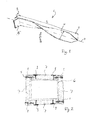
- The invention is described in more detail with reference to the accompanying drawings, in which:
- Fig. 1
- is a schematic perspective view of a fastening member according to an embodiment of the invention;
- Fig. 2
- is a schematic cross-sectional view of a ventilation duct fitted with an insulation system according to an embodiment of the invention; and
- Fig. 3
- is a top view of an elongated strip of sheet material for forming a fastening member according to an embodiment of the invention.
- In
fig. 1 there is shown an embodiment of a fastening member 1 according to the invention. The fastening member 1 is made from an elongated strip of metal 1' (seefig. 3 ) which has an insertion end 2 and a head end 3 and which is twisted about half a turn between said ends 2, 3 around a longitudinal axis 4. The twisting angle is preferably identical over the full length L of the fastening member, even though it might vary slightly. The insertion end 2 is preferably formed as a pointed end 2 as shown in the figures. Abended portion 5 is formed at the head end 3 by bending the end of the elongated strip 1' around the folding line 5' (seefig. 3 ) to a substantially perpendicular position relative to the longitudinal axis 4 and the rest of the strip 1'. - The fastening member 1 is found particularly advantageous in relation to corner connections between fire protection mineral wool insulation boards or
panels 7, such as shown infig. 2 . One of the issues with the connection between thefire protection boards 7 at the corners of a ventilation duct 6 is to ensure that no gaps appear due to for instance inaccurate cutting of the boards and/or to prevent gaps to appear due to heat expansion of the steel duct 6 which thefire protection boards 7 are arranged around. The fireprotection insulation boards 7 may be fitted to the surface of the duct 6 by heat-resistant glue and/or welding pins 8. However, at the corner assemblies there may still be a problem if the twoinsulation boards 7 adjacent each other provide a gap in the insulation. In order to overcome this, fastening members 1 according to the invention are provided in order to secure the corner assembly of theinsulation boards 7. - The elongated strip is preferably cut out of a steel plate, e.g. a 0.7-0.8 mm steel plate. The preferred thickness T can vary depending on the choice of material between 0.6-1.2 mm. A preferred choice of material is steel since it is well suited to fire protection systems and is readily available and reasonably priced. However, other materials may be used under the circumstances, such as plastic or the like depending on how thermo-resistant the fastening members need to be.
- The width W of the fastening member 1 may be chosen to fit a specific use. When the insulation boards or
panels 7 are made of mineral wool a width W between 10 and 30 mm, such as 20 mm has shown to be suitable. With this dimension it is relatively easy to push the fastening member 1 into theinsulation boards 7 by hand. - By the fastening members 1 according to the shown embodiment of the invention, it is found advantageous that the twist is about half a turn or 180º around the longitudinal axis 4. However the amount of twist can be more or less than this as long as it is sufficient to establish a good pull-out resistance in a given application. The twist is preferably constant over the full length L, even though he twisting angle by increase from one end of the fastening member to the other end.
- The
bended portion 5 at the head end 3 of the fastening member 1 functions as a push and turn handle during the mounting which can be done manually without use of a tool. After mounting the flatbended portion 5 is visible on the outside of the fire protection mineralwool fibre boards 7 so that it can be visibly controlled that the fastening member 1 has been mounted. - The fastening member 1 is made of a thin, flat piece of sheet metal. This strip of sheet metal is elongated with a width-to-length ratio of between 1:4 and 1:8, more preferably 1:6. It has turned out that this ensures a sufficient pull-out resistance with a twist of less than a full turn, preferably only half a turn. The relative wide blade-like twist of a thin, flat strip of sheet material, unlike e.g. a screw with a tread of several revolutions, ensures this fastening member 1 its pull-out resistance whilst at the same time ensures that it is easy to mount in the insulation boards, and is therefore particularly useful in the application of interconnecting mineral insulation boards, such as described above.
Claims (12)
- A fastening member for joining two insulation panels by manually inserting the fastening member into the insulation panels, said fastening member having an insertion end and a head end, characterised in that the fastening member is made of an elongated strip of sheet material having a longitudinal axis and which is twisted around its longitudinal axis.
- A fastening member according to claim 1, wherein at the head end the fastening member is provided with a bended portion, the bended portion preferably being bended approx. 90º in relation to the longitudinal axis.
- A fastening member according to claim 1 or 2, wherein the sheet material is twisted between 90º and 360º, preferably 180º, around the longitudinal axis.
- A fastening member according to any of the preceding claims, wherein the insertion end is pointed.
- A fastening member according to any of the preceding claims, wherein the sheet material has a thickness of 0.6-1.2 mm, preferably approx. 0.7-0.8 mm.
- A fastening member according to any of the preceding claims, wherein the sheet material is steel.
- A fastening member according to any of the preceding claims, wherein the elongated strip of sheet material from which the fastening member is formed has a width-to-length ration of between 1:4 and 1:8, preferably approx. 1:6.
- A system of insulation panels mounted around a building structure, such as a ventilation duct or the like, wherein at least two insulation panels adjacent each other are joined by at least one fastening member by manually inserting the at least one fastening member into the insulation panels, said fastening member having an insertion end and a head end, characterised in that the fastening member is made of an elongated strip of sheet material having a longitudinal axis and which is twisted around its longitudinal axis.
- A system according to claim 8, wherein the insulation panels are mineral wool panels, preferably with a density of 30-250 kg/m3, more preferably 50-200 kg/m3, most preferably 70-180 kg/m3.
- A system according to claim 8 or 9, wherein the fastening member has a length which corresponds to approximately twice the thickness of the insulation panels.
- A system according to any of claims 8 to 10, wherein the thickness of the insulation panels is 40-100 mm, preferably 60-80 mm, and the length of the fastening member is 80 to 200 mm, preferably 120-160 mm.
- A system according to any of claims 8 to 11, wherein the fastening member is according to any of the claims 1 to 7.
Priority Applications (1)
| Application Number | Priority Date | Filing Date | Title |
|---|---|---|---|
| EP13160800.2A EP2784334A1 (en) | 2013-03-25 | 2013-03-25 | A fastening member and a system for joining insulation panels |
Applications Claiming Priority (1)
| Application Number | Priority Date | Filing Date | Title |
|---|---|---|---|
| EP13160800.2A EP2784334A1 (en) | 2013-03-25 | 2013-03-25 | A fastening member and a system for joining insulation panels |
Publications (1)
| Publication Number | Publication Date |
|---|---|
| EP2784334A1 true EP2784334A1 (en) | 2014-10-01 |
Family
ID=47997115
Family Applications (1)
| Application Number | Title | Priority Date | Filing Date |
|---|---|---|---|
| EP13160800.2A Withdrawn EP2784334A1 (en) | 2013-03-25 | 2013-03-25 | A fastening member and a system for joining insulation panels |
Country Status (1)
| Country | Link |
|---|---|
| EP (1) | EP2784334A1 (en) |
Citations (7)
| Publication number | Priority date | Publication date | Assignee | Title |
|---|---|---|---|---|
| GB192492A (en) * | 1921-11-03 | 1923-02-05 | Frank Humphris | Improvements in and relating to nails, staples, spikes, hooks, brads, brobs or the like |
| US2215205A (en) * | 1939-07-11 | 1940-09-17 | Pacific State Box And Basket C | Fastening device |
| FR2118660A5 (en) * | 1970-12-15 | 1972-07-28 | Mustad Et Son As | |
| FR2656893A1 (en) * | 1990-01-10 | 1991-07-12 | Laurent Gerard | Tent anchoring stake (peg) |
| US6279287B1 (en) * | 1998-08-12 | 2001-08-28 | Shoshone Station Llc | Prefabricated building panel and method of manufacturing same |
| US20030180121A1 (en) * | 2000-11-28 | 2003-09-25 | Evening Star International, Llc | Metal piercing fastener with optimally resilient securing member |
| WO2005036070A1 (en) * | 2003-10-06 | 2005-04-21 | Saint-Gobain Isover | Air-conditioning and ventilating duct |
-
2013
- 2013-03-25 EP EP13160800.2A patent/EP2784334A1/en not_active Withdrawn
Patent Citations (7)
| Publication number | Priority date | Publication date | Assignee | Title |
|---|---|---|---|---|
| GB192492A (en) * | 1921-11-03 | 1923-02-05 | Frank Humphris | Improvements in and relating to nails, staples, spikes, hooks, brads, brobs or the like |
| US2215205A (en) * | 1939-07-11 | 1940-09-17 | Pacific State Box And Basket C | Fastening device |
| FR2118660A5 (en) * | 1970-12-15 | 1972-07-28 | Mustad Et Son As | |
| FR2656893A1 (en) * | 1990-01-10 | 1991-07-12 | Laurent Gerard | Tent anchoring stake (peg) |
| US6279287B1 (en) * | 1998-08-12 | 2001-08-28 | Shoshone Station Llc | Prefabricated building panel and method of manufacturing same |
| US20030180121A1 (en) * | 2000-11-28 | 2003-09-25 | Evening Star International, Llc | Metal piercing fastener with optimally resilient securing member |
| WO2005036070A1 (en) * | 2003-10-06 | 2005-04-21 | Saint-Gobain Isover | Air-conditioning and ventilating duct |
Similar Documents
| Publication | Publication Date | Title |
|---|---|---|
| US10221574B2 (en) | Insulting structure for buildings | |
| EP2683531B1 (en) | Fastener for securing a pipe of an under floor heating system | |
| EP3196373A1 (en) | Dry wall and sealing device for sealing a gap in dry wall | |
| US20190100920A1 (en) | Roof Construction | |
| US11566418B2 (en) | Bracing device for securing a facing | |
| EP2488781A1 (en) | Device and method for attachment of insulation | |
| EP3140597B1 (en) | Ducting systems | |
| CH696546A5 (en) | Fastening element for fastening on building of insulating course and ventilated protective layer, has metal shaft inserted from outside into insulating course and with first and second load application elements on respective ends | |
| DE19840076A1 (en) | Double-skin roof system | |
| US20100043328A1 (en) | Under rafter insulation system for a high pitched roof | |
| WO2014086332A1 (en) | Insulating arrangement and method for producing non-contact, thermal and acoustic insulation | |
| WO2009013493A1 (en) | Fixing | |
| US12312801B2 (en) | Bracket assembly including a fiber reinforced polymer bracket having a backer and method of use thereof | |
| EP3935318B1 (en) | Temperature control system | |
| DE202018006493U1 (en) | Insulation layer for a surface temperature control device and thermally conductive layer for an insulation layer | |
| DE202009013846U1 (en) | Rectangular element for attaching loads to ETICS facades | |
| WO2024197325A1 (en) | Element for forming a wall or a roof of a building | |
| DE69312025T2 (en) | Multi-shell element with flexible insulating plates between the walls of this element | |
| EP3818221B1 (en) | Method and means for making a wall by means of securing drywall panels to a background | |
| US9121176B2 (en) | Thermal clip for building construction | |
| EP1576327B1 (en) | Inner compartment for a refrigerating appliance | |
| DE29824901U1 (en) | Insulating sleeve for pipes - comprises an outer protective layer, an inner sliding layer, and an intermediate temp. and/or fire resistant layer | |
| DE202004002166U1 (en) | Heating device with pipes set in insulation board, e.g. for underfloor heating, contains undercut grooves for pipes and is covered with thermally conductive film | |
| EP3168542B1 (en) | Area temperature control system, heat exchanger assembly, method and method of installation | |
| GB2514533A (en) | Ducting systems |
Legal Events
| Date | Code | Title | Description |
|---|---|---|---|
| 17P | Request for examination filed |
Effective date: 20130325 |
|
| AK | Designated contracting states |
Kind code of ref document: A1 Designated state(s): AL AT BE BG CH CY CZ DE DK EE ES FI FR GB GR HR HU IE IS IT LI LT LU LV MC MK MT NL NO PL PT RO RS SE SI SK SM TR |
|
| AX | Request for extension of the european patent |
Extension state: BA ME |
|
| PUAI | Public reference made under article 153(3) epc to a published international application that has entered the european phase |
Free format text: ORIGINAL CODE: 0009012 |
|
| STAA | Information on the status of an ep patent application or granted ep patent |
Free format text: STATUS: THE APPLICATION IS DEEMED TO BE WITHDRAWN |
|
| 18D | Application deemed to be withdrawn |
Effective date: 20150402 |