EP2784251A2 - Motor vehicle lock - Google Patents
Motor vehicle lock Download PDFInfo
- Publication number
- EP2784251A2 EP2784251A2 EP14161236.6A EP14161236A EP2784251A2 EP 2784251 A2 EP2784251 A2 EP 2784251A2 EP 14161236 A EP14161236 A EP 14161236A EP 2784251 A2 EP2784251 A2 EP 2784251A2
- Authority
- EP
- European Patent Office
- Prior art keywords
- crash
- motor vehicle
- pawl
- engagement
- arrangement
- Prior art date
- Legal status (The legal status is an assumption and is not a legal conclusion. Google has not performed a legal analysis and makes no representation as to the accuracy of the status listed.)
- Granted
Links
- 238000010168 coupling process Methods 0.000 claims abstract description 59
- 238000005859 coupling reaction Methods 0.000 claims abstract description 59
- 230000008878 coupling Effects 0.000 claims abstract description 58
- 230000000903 blocking effect Effects 0.000 claims abstract description 6
- 230000001133 acceleration Effects 0.000 description 3
- 229910000639 Spring steel Inorganic materials 0.000 description 2
- 239000000463 material Substances 0.000 description 2
- 238000006243 chemical reaction Methods 0.000 description 1
- 230000000694 effects Effects 0.000 description 1
- 239000002184 metal Substances 0.000 description 1
- 239000007769 metal material Substances 0.000 description 1
- 230000002265 prevention Effects 0.000 description 1
- 238000007493 shaping process Methods 0.000 description 1
Images

Classifications
-
- E—FIXED CONSTRUCTIONS
- E05—LOCKS; KEYS; WINDOW OR DOOR FITTINGS; SAFES
- E05B—LOCKS; ACCESSORIES THEREFOR; HANDCUFFS
- E05B77/00—Vehicle locks characterised by special functions or purposes
- E05B77/02—Vehicle locks characterised by special functions or purposes for accident situations
- E05B77/04—Preventing unwanted lock actuation, e.g. unlatching, at the moment of collision
-
- Y—GENERAL TAGGING OF NEW TECHNOLOGICAL DEVELOPMENTS; GENERAL TAGGING OF CROSS-SECTIONAL TECHNOLOGIES SPANNING OVER SEVERAL SECTIONS OF THE IPC; TECHNICAL SUBJECTS COVERED BY FORMER USPC CROSS-REFERENCE ART COLLECTIONS [XRACs] AND DIGESTS
- Y10—TECHNICAL SUBJECTS COVERED BY FORMER USPC
- Y10T—TECHNICAL SUBJECTS COVERED BY FORMER US CLASSIFICATION
- Y10T292/00—Closure fasteners
- Y10T292/08—Bolts
- Y10T292/0908—Emergency operating means
Definitions
- the invention is directed to a motor vehicle lock according to the general part of claim 1, to a motor vehicle lock according to the general part of claim 12 and to a motor vehicle door arrangement according to claim 14.
- the motor vehicle lock in question is assigned to a motor vehicle door arrangement which comprises at least a motor vehicle door.
- the expression "motor vehicle door” is to be understood in a broad sense. It includes in particular side doors, back doors, lift gates, trunk lids or engine hoods. Such a motor vehicle door may generally be designed as a sliding door as well.
- crash safety plays an important role for today's motor vehicle locks. It is of particular importance that neither crash induced acceleration nor crash induced deformation leads to an unintended opening of the motor vehicle door which the motor vehicle door lock is assigned to.
- the focus of the present application is to prevent an unintended opening of the motor vehicle door based on crash induced deformation, for example a crash induced deformation of a door body shell.
- the known motor vehicle lock ( WO 2012/130201 A2 ), which is the starting point for the invention, is provided with a crash mechanism which prevents a crash induced and unintended opening of the motor vehicle door.
- a crash mechanism which prevents a crash induced and unintended opening of the motor vehicle door.
- the crash mechanism comprises a crash element which is actually a blocking element for a pawl actuation lever. When the crash mechanism is in its crash condition, the actuation of the pawl actuation lever is being blocked by the crash element.
- the known motor vehicle lock is generally advantageous as it reacts to crash induced deformation, and not to crash induced acceleration. With this it is possible to react to crash induced situations that require the prevention of opening of the motor vehicle door but that, however, do not show high crash induced accelerations.
- a disadvantage of the known motor vehicle lock is the difficult design of the drive train that allows opening the motor vehicle door by an outer door handle or the like.
- the crash mechanism of the known motor vehicle lock reacts to the crash induced deformation by blocking part of the drive train, the crash induced actuaion forces on the outer door handle are being transferred into the motor vehicle lock.
- this drive train has to be designed for correspondingly high actuation forces.
- those high crash induced actuation forces may not even be present during the above noted, crash induced deformation such that in the end for many crash situations the drive train would be oversized.
- the basic idea underlying the present invention is to let the pawl actuation arrangement run free in case a crash induced deformation brings the crash mechanism into the crash condition.
- the drive train assigned to the actuation arrangement may be designed in view of rather low actuation forces even in view of the occurrence of a possible crash.
- a switchable coupling is provided between the pawl actuation arrangement and the pawl, wherein the crash element is acting on the switchable coupling or is part of the switchable coupling in such a way that bringing the crash mechanism into the crash condition opens the switchable coupling and therewith lets an actuation of the pawl actuation arrangement run free.
- the crash mechanism as well as the switchable coupling may be designed for low actuation forces as well. As a result a considerable cost reduction may be achieved with the present invention.
- the crash mechanism comprises a crash engagement element which serves for receiving the crash induced deformation of a corresponding component like a door body shell.
- the crash engagement element is coupled correspondingly with the crash element.
- the crash element and the crash engagement element are being designed as a one-piece component.
- the switchable coupling is not only used by the crash mechanism, but also by the lock mechanism, namely to realize the different functional states, such as "unlocked” and "locked". This double-use of the switchable coupling plays an important role for the above noted, cost effective design.
- a second teaching according to claim 12, which is independently important, is directed to the idea of providing at least part of the crash engagement element by a bendable wire or strip. It has been found that this basic idea is not only cost effective, but that a bendable wire or strip can receive a crash induced deformation movement in an optimal way. The bendability guarantees a certain amount of deformation of the crash engagement element itself without breaking it, such that the function of the crash engagement element is always guaranteed.
- the second teaching proposes for a motor vehicle lock according to the general part of claim 12, that the crash mechanism comprises a crash engagement element for engagement of the component of the motor vehicle door arrangement, which component is being deformed by a crash, that the crash engagement element is coupled to the crash element in order to transfer at least part of the crash induced deformation movement to the crash element and that at least part of the crash engagement element is provided by a bendable wire or strip.
- the bendable wire or strip is composed of a metal material, preferably spring steel. It may however also be advantageous for the bendable wire or strip to be formed from a plastic material.
- the bendable wire preferably has a circular cross section.
- the strip preferable has a rectangular cross section.
- a third teaching according to claim 14, which is independently important as well, is directed to a motor vehicle door arrangement with a motor vehicle door and a motor vehicle lock.
- the motor vehicle lock is arranged in or at the motor vehicle door.
- the motor vehicle lock then interacts with a lock striker which is arranged at the motor vehicle body.
- the motor vehicle lock for this motor vehicle door arrangement is one of the above noted, proposed motor vehicle locks. Accordingly it may be referred to all explanations given with respect to the proposed motor vehicle locks.
- the motor vehicle lock 1 shown in the drawings is assigned a motor vehicle door arrangement 2, which comprises a motor vehicle door 2a besides said motor vehicle lock 1.
- a motor vehicle door arrangement 2 which comprises a motor vehicle door 2a besides said motor vehicle lock 1.
- the motor vehicle door 2a is a side door of the motor vehicle.
- the motor vehicle lock 1 comprises the usual locking elements catch 3 and pawl 4, which is assigned to the catch 3.
- the catch 3 can be brought into an open position (not shown) and into a closed position ( Fig. 1 ). In the closed position shown in Fig. 1 the catch 3 is or may be brought into holding engagement with a lock striker 5 that is indicated in Fig. 1 as well.
- the motor vehicle lock 1 is normally arranged at or in the motor vehicle door 2a, while the lock striker 5 is arranged at the motor vehicle body.
- the pawl 4 may be brought into an engagement position shown in Fig. 1 , in which it is in blocking engagement with the catch 3.
- the pawl 4 may be deflected into a release position (not shown), which would be a deflection in the clockwise direction in Fig. 1 .
- a lock mechanism 6 is provided, which may be brought into different functional states, such as “unlocked” and “locked” via a lock actuation arrangement 7.
- a pawl actuation arrangement 8 is provided, by which actuation the pawl 4 may be deflected into the released position depending on the functional state of the lock mechanism 6.
- Figs. 2 to 4 show the motor vehicle lock according to Fig. 1 omitting for example the catch 3 and various housing details for easy understanding.
- the pawl actuation arrangement 8 here and preferably serves to deflect the pawl 4 into its release position by the actuation of an outer door handle, not shown.
- the pawl actuation arrangement 8 comprises at least a pawl actuation lever 8a which may be connected to the outer door handle via a bowden cable or the like. For actuation the pawl actuation lever 8a is being pivoted in clockwise direction.
- the motor vehicle lock 1 is also provided with a crash mechanism 9 with a crash element 9a, which crash mechanism 9 may be brought from a normal condition ( Fig. 2 , 3 ) into a crash condition ( Fig. 4 ) by engagement of the crash mechanism 9 with a component 10 of the motor vehicle door arrangement, here and preferably with a door body shell 11, which component 10 is being deformed due to a crash.
- a comparison of Figs. 1 and 4a ) shows that the door body shell 11 has been deformed in the drawings to the right thereby moving at least a part of the crash mechanism 9 with the crash induced deformation.
- a switchable coupling 12 is provided between the pawl actuation arrangement 8 and the pawl 4 and that the crash element 9a is acting on the switchable coupling 12 in such a way that bringing the crash mechanism 9 into the crash condition ( Fig. 4 ) opens the switchable coupling 12 and therewith lets an actuation of the pawl actuation arrangement 8 run free ( Fig. 4b )).
- the crash mechanism 9 For reception of the above noted crash induced deformation the crash mechanism 9 comprises a crash engagement element 9b, which is designed for engagement of the respective component 10 of the motor vehicle door arrangement, which component 10 is being deformed by a crash.
- the crash engagement element 9b is coupled to the crash element 9a in order to transfer at least part of the crash induced deformation movement to the crash element 9a.
- a comparison of Fig. 2a ) with Fig. 4a ) shows that the crash induced deformation leads to a movement of the crash engagement element 9b which as a result leads to pivoting the crash element 9a in a counter clockwise direction in the drawings.
- the switchable coupling 12 is used not only by the crash mechanism 9, but also by the lock mechanism 6.
- the lock mechanism 6 acts on the switchable coupling 12 for realizing the functional states “unlocked” and “locked” such that in the functional state “unlocked” the switchable coupling 12 closes the drive train ( Fig. 2 ) and in the functional state “locked” opens the drive train ( Fig. 3 ).
- the lock actuation arrangement 7 is designed as a lever, which acts on the switchable coupling 12, in particular on a coupling lever 13 to be described, as shown in Fig. 3 . In the functional state "locked” the actuation arrangement 7 moves the coupling lever 13 counter clockwise which leads to the switching coupling 12 to be opened.
- the lock actuation arrangement 7 may be operated manually by the user or motor driven by a central locking drive.
- the switchable coupling 12 shown in the drawings is of simple structure and comprises said coupling lever 13 which is part of the drive train between the pawl actuation arrangement 8 and the pawl 4.
- the coupling lever 13 may be brought into a closed state in which it closes the drive train ( Fig. 2 ) and into an open state in which it opens the drive train ( Fig. 3 , 4 ).
- the coupling lever 13 is pivotable around a coupling lever axis 13a as may be seen from a comparison between the Figs. 2a ) and 4a ).
- the pawl actuation arrangement 8 comprises the noted pawl actuation lever 8a which is pivotable around a pawl actuation lever axis 8b.
- the coupling lever 13 is linked to the pawl actuation lever 8a eccentrically to the pivot axis 8b of the pawl actuation lever 8a. This means that the coupling lever axis 13a is offset to the pawl actuation lever axis 8b.
- the coupling lever 13 here and preferably is of oblong design and comprises the coupling lever axis 13a on one end and an engagement area 14 on the other end.
- the coupling lever 13 comprises said engagement area 14 while a subsequent drive train component, here and preferably a pawl lever 15, comprises a counter engagement area 16.
- the pawl lever 15 is coupled to the pawl 4 such that pivoting of the pawl lever 15 in the clockwise direction leads to deflecting the pawl 4 in the clockwise direction as well which leads to deflecting the pawl 4 into its release position.
- the pawl lever 15 may always be coupled to the pawl 4 or may be coupled to the pawl 4 only if needed.
- the switchable coupling 12 is mainly based on the engagement area 14 and the counter engagement area 16 which makes the coupling very simple in constructional view.
- both engagement areas 14, 16 are simply realized as edges that for closing the switchable coupling 12 come into engagement with each other. This makes it possible that opening the switchable coupling 12 is even possible while the engagement areas 14, 16 are in coupling engagement.
- the coupling lever 13 is pretensioned into its closed state which corresponds to the closed state of the switchable coupling 12.
- the coupling lever 13 is accordingly pretensioned in clockwise direction.
- the crash element 9a is pivotable around a crash element axis 17 and comprises an arm 18 in order to come into engagement with the switchable coupling 12, here and preferably with the coupling lever 13, when the crash mechanism 9 is being brought into the crash condition as shown in Fig. 4 .
- the crash element 9a may, however, be movable in another way, for example in a linear manner.
- the crash engagement element 9b is at least partly located at the outside of the motor vehicle lock 1.
- the crash engagement element 9b comprises a bow like section 19 which at least at two end portions 20, 21 is being supported by a support arrangement 22.
- the support arrangement 22a On one end portion 20 the support arrangement 22a is part of a housing component 23, which is shown in Fig. 1 in dotted lines.
- the support arrangement 22b At the other end portion 21 the support arrangement 22b is provided by the crash element 9a.
- the crash element 9a comprises a reception 24 for the crash engagement element 9b.
- the crash engagement element 9b is realised in a very simple way according to the drawings.
- the crash engagement element 9b is provided by a bendable wire or strip.
- the wire or strip is preferably made of metal, further preferably of spring steel as noted above.
- the crash engagement element 9b may be formed in a way that the bendability is guaranteed as needed.
- the bendable wire or strip may be at least partly be elastically bendable. Generally it is possible, however, that the bendability is completely non elastic.
- a motor vehicle lock 1 with a crash mechanism 9 comprising a crash engagement element 9b provided by a bendable wire or strip is subject of a second teaching.
- a lock mechanism 6 as well as a crash mechanism 9 based on the above noted free run concept is not necessary for this teaching.
- Other than that all explanations, advantages and alternatives given above are fully applicable to the second teaching.
- a motor vehicle door arrangement 2 with a motor vehicle door 2a and assigned to the motor vehicle door 2a and a motor vehicle lock 1 according to the above noted teachings is claimed. Again, all explanations, advantages and alternatives given for the above noted teachings are fully applicable to this third teaching.
- the motor vehicle door arrangement 2 comprises a motor vehicle door 2a with a door body shell 11, wherein the crash engagement element 9b of the crash mechanism 9 is arranged adjacent the door body shell 11. Further preferably the distance between the door body shell 11 and the crash engagement element 9b is less than 20 mm, further preferably less than 10 mm. With this arrangement of the crash engagement element 9b a short-term reaction of the crash mechanism 9 to crash induced deformations can be guaranteed.
Landscapes
- Lock And Its Accessories (AREA)
- Engineering & Computer Science (AREA)
- Mechanical Engineering (AREA)
Abstract
Description
- The invention is directed to a motor vehicle lock according to the general part of
claim 1, to a motor vehicle lock according to the general part ofclaim 12 and to a motor vehicle door arrangement according toclaim 14. - The motor vehicle lock in question is assigned to a motor vehicle door arrangement which comprises at least a motor vehicle door. The expression "motor vehicle door" is to be understood in a broad sense. It includes in particular side doors, back doors, lift gates, trunk lids or engine hoods. Such a motor vehicle door may generally be designed as a sliding door as well.
- The crash safety plays an important role for today's motor vehicle locks. It is of particular importance that neither crash induced acceleration nor crash induced deformation leads to an unintended opening of the motor vehicle door which the motor vehicle door lock is assigned to. The focus of the present application is to prevent an unintended opening of the motor vehicle door based on crash induced deformation, for example a crash induced deformation of a door body shell.
- The known motor vehicle lock (
WO 2012/130201 A2 ), which is the starting point for the invention, is provided with a crash mechanism which prevents a crash induced and unintended opening of the motor vehicle door. In case of a crash induced deformation of a door body shell the respective section of the door body shell comes into engagement with the crash mechanism which leads to the crash mechanism being brought from a normal condition into a crash condition. The crash mechanism comprises a crash element which is actually a blocking element for a pawl actuation lever. When the crash mechanism is in its crash condition, the actuation of the pawl actuation lever is being blocked by the crash element. - The known motor vehicle lock is generally advantageous as it reacts to crash induced deformation, and not to crash induced acceleration. With this it is possible to react to crash induced situations that require the prevention of opening of the motor vehicle door but that, however, do not show high crash induced accelerations.
- A disadvantage of the known motor vehicle lock is the difficult design of the drive train that allows opening the motor vehicle door by an outer door handle or the like. As the crash mechanism of the known motor vehicle lock reacts to the crash induced deformation by blocking part of the drive train, the crash induced actuaion forces on the outer door handle are being transferred into the motor vehicle lock. In order to prevent non-reproducable breakage of the drive train, this drive train has to be designed for correspondingly high actuation forces. As noted above, however, those high crash induced actuation forces may not even be present during the above noted, crash induced deformation such that in the end for many crash situations the drive train would be oversized.
- It is the object of the invention to improve the known motor vehicle lock such that a cost effective constructional design is possible without reducing the resulting crash safety.
- The above noted object is solved for a motor vehicle lock according to the general part of
claim 1 with the features of the characterizing part ofclaim 1. - The basic idea underlying the present invention is to let the pawl actuation arrangement run free in case a crash induced deformation brings the crash mechanism into the crash condition. With this the drive train assigned to the actuation arrangement may be designed in view of rather low actuation forces even in view of the occurrence of a possible crash.
- In further detail a switchable coupling is provided between the pawl actuation arrangement and the pawl, wherein the crash element is acting on the switchable coupling or is part of the switchable coupling in such a way that bringing the crash mechanism into the crash condition opens the switchable coupling and therewith lets an actuation of the pawl actuation arrangement run free.
- In addition to the cost effective design of the above noted drive train the crash mechanism as well as the switchable coupling may be designed for low actuation forces as well. As a result a considerable cost reduction may be achieved with the present invention.
- According to claim 2 the crash mechanism comprises a crash engagement element which serves for receiving the crash induced deformation of a corresponding component like a door body shell. For transfer of the deformation movement the crash engagement element is coupled correspondingly with the crash element. In a preferred embodiment the crash element and the crash engagement element are being designed as a one-piece component.
- According to
claim 3 it is interesting that the switchable coupling is not only used by the crash mechanism, but also by the lock mechanism, namely to realize the different functional states, such as "unlocked" and "locked". This double-use of the switchable coupling plays an important role for the above noted, cost effective design. - The further preferred embodiments according to
claims 4 to 11 are directed to preferred constructional measures. Especially the embodiment according to claim 11 leads to outstanding cost savings regarding the production of the motor vehicle lock. - A second teaching according to
claim 12, which is independently important, is directed to the idea of providing at least part of the crash engagement element by a bendable wire or strip. It has been found that this basic idea is not only cost effective, but that a bendable wire or strip can receive a crash induced deformation movement in an optimal way. The bendability guarantees a certain amount of deformation of the crash engagement element itself without breaking it, such that the function of the crash engagement element is always guaranteed. - It is to be understood that for the second teaching it is not in any case necessary to have a lock mechanism and/or a crash mechanism based on the above noted free run concept.
- Accordingly, the second teaching proposes for a motor vehicle lock according to the general part of
claim 12, that the crash mechanism comprises a crash engagement element for engagement of the component of the motor vehicle door arrangement, which component is being deformed by a crash, that the crash engagement element is coupled to the crash element in order to transfer at least part of the crash induced deformation movement to the crash element and that at least part of the crash engagement element is provided by a bendable wire or strip. - With regard to the material selection for the bendable wire or strip, various preferred alternatives are possible. In one particularily preferred development, the bendable wire or strip is composed of a metal material, preferably spring steel. It may however also be advantageous for the bendable wire or strip to be formed from a plastic material.
- For the shaping of the bendable wire or strip, various advantageous alternatives are considerable as well. The bendable wire preferably has a circular cross section. The strip preferable has a rectangular cross section.
- A third teaching according to
claim 14, which is independently important as well, is directed to a motor vehicle door arrangement with a motor vehicle door and a motor vehicle lock. Preferably the motor vehicle lock is arranged in or at the motor vehicle door. The motor vehicle lock then interacts with a lock striker which is arranged at the motor vehicle body. The motor vehicle lock for this motor vehicle door arrangement is one of the above noted, proposed motor vehicle locks. Accordingly it may be referred to all explanations given with respect to the proposed motor vehicle locks. - In the following the invention will be described in an example referring to the drawings. In the drawings show
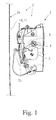
- Fig. 1
- a proposed motor vehicle lock in top view omitting part of the housing,
- Fig. 2
- the motor vehicle lock according to
Fig. 1 omitting further components- a) in the unlocked functional state without actuation and
- b) in the unlocked functional state during actuation,
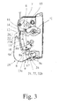
- Fig. 3
- the proposed motor vehicle lock according to the display of
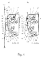
Fig. 2 in the locked functional state without actuation and - Fig. 4
- the proposed motor vehicle lock according to the display of
Fig. 2 - a) with the crash mechanism in the crash condition without actuation and
- b) with the crash mechanism in the crash condition during actuation.
- The
motor vehicle lock 1 shown in the drawings is assigned a motor vehicle door arrangement 2, which comprises amotor vehicle door 2a besides saidmotor vehicle lock 1. Regarding the broad interpretation of the expression "motor vehicle door" reference is made to the introductory part of the specification. Here and preferably themotor vehicle door 2a is a side door of the motor vehicle. - The
motor vehicle lock 1 comprises the usual locking elements catch 3 andpawl 4, which is assigned to thecatch 3. Thecatch 3 can be brought into an open position (not shown) and into a closed position (Fig. 1 ). In the closed position shown inFig. 1 thecatch 3 is or may be brought into holding engagement with alock striker 5 that is indicated inFig. 1 as well. Themotor vehicle lock 1 is normally arranged at or in themotor vehicle door 2a, while thelock striker 5 is arranged at the motor vehicle body. - The
pawl 4 may be brought into an engagement position shown inFig. 1 , in which it is in blocking engagement with thecatch 3. Here an preferably thepawl 4 blocks thecatch 3 in its closed position in a mechanically stable manner such that thepawl 4 itself does not have to be blocked. For release of thecatch 3 into its open position thepawl 4 may be deflected into a release position (not shown), which would be a deflection in the clockwise direction inFig. 1 . - Further, a
lock mechanism 6 is provided, which may be brought into different functional states, such as "unlocked" and "locked" via alock actuation arrangement 7. In addition apawl actuation arrangement 8 is provided, by which actuation thepawl 4 may be deflected into the released position depending on the functional state of thelock mechanism 6. -
Figs. 2 to 4 show the motor vehicle lock according toFig. 1 omitting for example thecatch 3 and various housing details for easy understanding. - The
pawl actuation arrangement 8 here and preferably serves to deflect thepawl 4 into its release position by the actuation of an outer door handle, not shown. For this, thepawl actuation arrangement 8 comprises at least apawl actuation lever 8a which may be connected to the outer door handle via a bowden cable or the like. For actuation thepawl actuation lever 8a is being pivoted in clockwise direction. - If the
lock mechanism 6 is in the functional state "unlocked" an actuation of thepawl actuation lever 8a causes the deflection of thepawl 4 into its release position. If thelock mechanism 6 is in its functional state "locked" the actuation of thepawl actuation lever 8a does not have any effect on thepawl 4. The detailled functionality of thelock mechanism 6 will be described further down. - The
motor vehicle lock 1 is also provided with acrash mechanism 9 with acrash element 9a, whichcrash mechanism 9 may be brought from a normal condition (Fig. 2 ,3 ) into a crash condition (Fig. 4 ) by engagement of thecrash mechanism 9 with a component 10 of the motor vehicle door arrangement, here and preferably with a door body shell 11, which component 10 is being deformed due to a crash. A comparison ofFigs. 1 and4a ) shows that the door body shell 11 has been deformed in the drawings to the right thereby moving at least a part of thecrash mechanism 9 with the crash induced deformation. - It is of particular importance now that a
switchable coupling 12 is provided between thepawl actuation arrangement 8 and thepawl 4 and that thecrash element 9a is acting on theswitchable coupling 12 in such a way that bringing thecrash mechanism 9 into the crash condition (Fig. 4 ) opens theswitchable coupling 12 and therewith lets an actuation of thepawl actuation arrangement 8 run free (Fig. 4b )). - For reception of the above noted crash induced deformation the
crash mechanism 9 comprises acrash engagement element 9b, which is designed for engagement of the respective component 10 of the motor vehicle door arrangement, which component 10 is being deformed by a crash. Thecrash engagement element 9b is coupled to thecrash element 9a in order to transfer at least part of the crash induced deformation movement to thecrash element 9a. A comparison ofFig. 2a ) withFig. 4a ) shows that the crash induced deformation leads to a movement of thecrash engagement element 9b which as a result leads to pivoting thecrash element 9a in a counter clockwise direction in the drawings. - It has been noted above that the
switchable coupling 12 is used not only by thecrash mechanism 9, but also by thelock mechanism 6. In particular thelock mechanism 6 acts on theswitchable coupling 12 for realizing the functional states "unlocked" and "locked" such that in the functional state "unlocked" theswitchable coupling 12 closes the drive train (Fig. 2 ) and in the functional state "locked" opens the drive train (Fig. 3 ). For this thelock actuation arrangement 7 is designed as a lever, which acts on theswitchable coupling 12, in particular on acoupling lever 13 to be described, as shown inFig. 3 . In the functional state "locked" theactuation arrangement 7 moves thecoupling lever 13 counter clockwise which leads to the switchingcoupling 12 to be opened. Thelock actuation arrangement 7 may be operated manually by the user or motor driven by a central locking drive. - The
switchable coupling 12 shown in the drawings is of simple structure and comprises saidcoupling lever 13 which is part of the drive train between thepawl actuation arrangement 8 and thepawl 4. Thecoupling lever 13 may be brought into a closed state in which it closes the drive train (Fig. 2 ) and into an open state in which it opens the drive train (Fig. 3 ,4 ). For this thecoupling lever 13 is pivotable around acoupling lever axis 13a as may be seen from a comparison between theFigs. 2a ) and4a ). In the shown and insofar preferred embodiment thepawl actuation arrangement 8 comprises the notedpawl actuation lever 8a which is pivotable around a pawlactuation lever axis 8b. In the shown embodiment thecoupling lever 13 is linked to thepawl actuation lever 8a eccentrically to thepivot axis 8b of thepawl actuation lever 8a. This means that thecoupling lever axis 13a is offset to the pawlactuation lever axis 8b. - The
coupling lever 13 here and preferably is of oblong design and comprises thecoupling lever axis 13a on one end and anengagement area 14 on the other end. - In general it is provided that the
coupling lever 13 comprises saidengagement area 14 while a subsequent drive train component, here and preferably apawl lever 15, comprises acounter engagement area 16. Thepawl lever 15 is coupled to thepawl 4 such that pivoting of thepawl lever 15 in the clockwise direction leads to deflecting thepawl 4 in the clockwise direction as well which leads to deflecting thepawl 4 into its release position. Depending on the application thepawl lever 15 may always be coupled to thepawl 4 or may be coupled to thepawl 4 only if needed. - While the
switchable coupling 12 is in the closed state (Fig. 2 ), by actuation of thepawl actuation arrangement 8, here and preferably by pivoting thepawl actuation lever 8a in clockwise direction, theengagement area 14 comes into engagement with thecounter engagement area 16 which leads to deflection of thepawl 4 into its release position (Fig. 2b )). - It may be taken from the drawings that the
switchable coupling 12 is mainly based on theengagement area 14 and thecounter engagement area 16 which makes the coupling very simple in constructional view. - It is particularily interesting that both
engagement areas switchable coupling 12 come into engagement with each other. This makes it possible that opening theswitchable coupling 12 is even possible while theengagement areas - As a result in case the
switchable coupling 12 is closed and thepawl actuation arrangement 8 is being actuated (Fig. 2b )), bringing thecrash mechanism 9 into the crash condition causes to open the switchable coupling which leads to a situation shown inFig. 4b ). - The
coupling lever 13 is pretensioned into its closed state which corresponds to the closed state of theswitchable coupling 12. In the drawings thecoupling lever 13 is accordingly pretensioned in clockwise direction. - The
crash element 9a is pivotable around acrash element axis 17 and comprises anarm 18 in order to come into engagement with theswitchable coupling 12, here and preferably with thecoupling lever 13, when thecrash mechanism 9 is being brought into the crash condition as shown inFig. 4 . Thecrash element 9a, may, however, be movable in another way, for example in a linear manner. - In order to provide a good adaptability of the
crash mechanism 9 to the respective motor vehicle door it is preferably so that thecrash engagement element 9b is at least partly located at the outside of themotor vehicle lock 1. - As shown in the drawings the
crash engagement element 9b comprises a bow likesection 19 which at least at twoend portions 20, 21 is being supported by asupport arrangement 22. On oneend portion 20 thesupport arrangement 22a is part of ahousing component 23, which is shown inFig. 1 in dotted lines. At the other end portion 21 the support arrangement 22b is provided by thecrash element 9a. For this thecrash element 9a comprises areception 24 for thecrash engagement element 9b. - The
crash engagement element 9b is realised in a very simple way according to the drawings. In further detail thecrash engagement element 9b is provided by a bendable wire or strip. The wire or strip is preferably made of metal, further preferably of spring steel as noted above. Thecrash engagement element 9b may be formed in a way that the bendability is guaranteed as needed. - The bendable wire or strip may be at least partly be elastically bendable. Generally it is possible, however, that the bendability is completely non elastic.
- A
motor vehicle lock 1 with acrash mechanism 9 comprising acrash engagement element 9b provided by a bendable wire or strip is subject of a second teaching. Alock mechanism 6 as well as acrash mechanism 9 based on the above noted free run concept is not necessary for this teaching. Other than that all explanations, advantages and alternatives given above are fully applicable to the second teaching. - According to a third teaching a motor vehicle door arrangement 2 with a
motor vehicle door 2a and assigned to themotor vehicle door 2a and amotor vehicle lock 1 according to the above noted teachings is claimed. Again, all explanations, advantages and alternatives given for the above noted teachings are fully applicable to this third teaching. - According to a particularly preferred embodiment, that may be applicable to all of the above, the motor vehicle door arrangement 2 comprises a
motor vehicle door 2a with a door body shell 11, wherein thecrash engagement element 9b of thecrash mechanism 9 is arranged adjacent the door body shell 11. Further preferably the distance between the door body shell 11 and thecrash engagement element 9b is less than 20 mm, further preferably less than 10 mm. With this arrangement of thecrash engagement element 9b a short-term reaction of thecrash mechanism 9 to crash induced deformations can be guaranteed.
Claims (15)
- Motor vehicle lock for a motor vehicle door arrangement (2), wherein a catch (3) and a pawl (4), which is assigned to the catch (3), are provided, wherein the catch (3) can be brought into an open position and into a closed position, wherein the catch (3), which is in the closed position, is or may be brought into holding engagement with a lock striker (5), wherein the pawl (4) may be brought into an engagement position, in which it is in blocking engagement with the catch (3) and wherein the pawl (4) may be deflected into a release position, in which it releases the catch (3),
wherein a lock mechanism (6) is provided, which may be brought into different functional states such as "unlocked" and "locked" via a lock actuation arrangement (7) and wherein a pawl actuation arrangement (8) is provided, by which actuation the pawl (4) may deflected into the release position depending on the functional state of the lock mechanism (6),
wherein a crash mechanism (9) with a crash element (9a) is provided, which crash mechanism (9) may be brought from a normal condition into a crash condition by engagement with a component (10) of the motor vehicle door arrangement (2), in particular a door body shell (11), which component (10) is being deformed due to a crash,
characterized in that
a switchable coupling (12) is provided between the pawl actuation arrangement (8) and the pawl (4) and that the crash element (9a) is acting on the switchable coupling (12) or is part of the switchable coupling (12) in such a way that bringing the crash mechanism (9) into the crash condition opens the switchable coupling (12) and therewith lets an actuation of the pawl actuation arrangement (8) run free. - Motor vehicle lock according to claim 1, characterized in that the crash mechanism (9) comprises a crash engagement element (9b) for engagement of the component (10) of the motor vehicle door arrangement (2), which component (10) is being deformed by a crash, and that the crash engagement element (9b) is coupled to the crash element (9a) in order to transfer at least part of the crash induced deformation movement to the crash element (9a).
- Motor vehicle lock according to claim 1 or 2, characterized in that the lock mechanism (6) acts on the switchable coupling (12) for realizing the functional states "unlocked" and "locked" such that in the functional state "unlocked" the switchable-coupling (12) closes and in the functional state "locked" opens.
- Motor vehicle lock according to any one of the preceding claims, characterized in that the switchable coupling (12) comprises a coupling lever (13) which is part of the drive train between the pawl actuation arrangement (8) and the pawl (4), that the coupling lever (13) may be brought into a closed state in which it closes the drive train and into an open state in which it opens the drive train.
- Motor vehicle lock according to any one of the preceding claims, characterized in that the pawl actuation arrangement (8) comprises a pawl actuation lever (8a) which is pivotable around a pawl actuation lever axis (8b) and that the coupling lever (13) is linked to the pawl actuation lever (8a) eccentrically with respect to the pawl actuation lever axis (8b).
- Motor vehicle lock according to any one of the preceding claims, characterized in that the coupling lever (13) comprises an engagement area (14) and that a subsequent drive train component (15), which is or may be coupled to the pawl (4), comprises a counter engagement area (16) and that while the switchable coupling (12) is in the closed state, by actuation of the pawl actuation arrangement (8), the engagement area (14) comes into engagement with the counter engagement area (16) for deflecting the pawl (4) into the release position.
- Motor vehicle lock according to any one of the preceding claims, characterized in that in case the switchable coupling (12) is closed and the pawl actuation arrangement (8) is being actuated, bringing the crash mechanism (9) into the crash condition causes to open the switchable coupling (12).
- Motor vehicle lock according to any one of the preceding claims, characterized in that the crash element (9a) is pivotable around a crash element axis (17) and comprises an arm (18) to come into engagement with the switchable coupling (12) when the crash mechanism (9) is being brought into the crash condition.
- Motor vehicle lock according to any one of the preceding claims, characterized in that the crash engagement element (9b) is at least partly located at the outside of the motor vehicle lock (1).
- Motor vehicle lock according to any one of the preceding claims, characterized in that the crash engagement element (9b) comprises a bow like section (19) which at least on two end portions (20, 21) is being supported by a support arrangement (22).
- Motor vehicle lock according to any one of the preceding claims, characterized in that at least part of the crash engagement element (9b) is provided by a bendable wire or strip.
- Motor vehicle lock for a motor vehicle door arrangement (2), wherein a catch (3) and a pawl (4), which is assigned to the catch (3), are provided, wherein the catch (3) can be brought into an open position and into a closed position, wherein the catch (3), which is in the closed position, is or may be brought into holding engagement with a lock striker (5), wherein the pawl (4) may be brought into an engagement position, in which it is in blocking engagement with the catch (3) and wherein the pawl (4) may be deflected into a release position, in which it releases the catch (3),
wherein a crash mechanism (9) with a crash element (9a) is provided, which crash mechanism (9) may be brought from a normal condition into a crash condition by engagement with a component (10) of the motor vehicle door arrangement (2), in particular a door body shell (11), which component (10) is being deformed due to a crash,
characterized in that
the crash mechanism (9) comprises a crash engagement element (9b) for engagement of the component (10) of the motor vehicle door arrangement (2), which component (10) is being deformed by a crash, that the crash engagement element (9b) is coupled to the crash element (9a) in order to transfer at least part of the crash induced deformation movement to the crash element (9a) and that at least part of the crash engagement element (9b) is provided by a bendable wire or strip. - Motor vehicle lock according to claim 12, characterized in that the bendable wire or strip provides a bow like section (19) which at least on two end portions (20, 21) is being supported by a support arrangement (22).
- Motor vehicle door arrangement with a motor vehicle door (2a) and assigned to the motor vehicle door (2a) a motor vehicle lock (1) according to one of the preceding claims.
- Motor vehicle door arrangement according to claim 14, characterized in that the motor vehicle door (2a) comprises a door body shell (11) and that a crash engagement element (9b) of the crash mechanism (9) is arranged adjacent the door body shell (11).
Applications Claiming Priority (2)
| Application Number | Priority Date | Filing Date | Title |
|---|---|---|---|
| US201361804910P | 2013-03-25 | 2013-03-25 | |
| US13/929,196 US9605449B2 (en) | 2013-03-25 | 2013-06-27 | Motor vehicle lock |
Publications (3)
| Publication Number | Publication Date |
|---|---|
| EP2784251A2 true EP2784251A2 (en) | 2014-10-01 |
| EP2784251A3 EP2784251A3 (en) | 2016-04-06 |
| EP2784251B1 EP2784251B1 (en) | 2018-09-26 |
Family
ID=50342246
Family Applications (1)
| Application Number | Title | Priority Date | Filing Date |
|---|---|---|---|
| EP14161236.6A Active EP2784251B1 (en) | 2013-03-25 | 2014-03-24 | Motor vehicle lock |
Country Status (2)
| Country | Link |
|---|---|
| US (1) | US9605449B2 (en) |
| EP (1) | EP2784251B1 (en) |
Cited By (1)
| Publication number | Priority date | Publication date | Assignee | Title |
|---|---|---|---|---|
| DE202016102211U1 (en) | 2016-04-26 | 2017-07-28 | Brose Schließsysteme GmbH & Co. Kommanditgesellschaft | Crash protection for a motor vehicle door |
Families Citing this family (13)
| Publication number | Priority date | Publication date | Assignee | Title |
|---|---|---|---|---|
| DE202009017667U1 (en) | 2009-12-26 | 2011-05-05 | BROSE SCHLIEßSYSTEME GMBH & CO. KG | Motor vehicle lock arrangement |
| DE102012025053A1 (en) * | 2012-12-21 | 2014-06-26 | BROSE SCHLIEßSYSTEME GMBH & CO. KG | Motor vehicle lock |
| CN203846892U (en) * | 2013-04-23 | 2014-09-24 | 三井金属爱科特株式会社 | Door locking device for vehicle |
| US9611675B2 (en) * | 2014-05-23 | 2017-04-04 | Brose Schliesssysteme Gmbh & Co. Kg | Motor vehicle door lock arrangement |
| US20150354255A1 (en) * | 2014-06-06 | 2015-12-10 | Brose Schliesssysteme Gmbh & Co. Kg | Lock arrangement for a motor vehicle |
| EP2980341B1 (en) | 2014-07-31 | 2019-11-06 | Brose Schliesssysteme GmbH & Co. KG | Motor vehicle door lock arrangement |
| US20160258194A1 (en) * | 2015-03-06 | 2016-09-08 | Brose Schliesssysteme Gmbh & Co. Kg | Motor vehicle lock |
| US10370874B2 (en) | 2015-09-14 | 2019-08-06 | Brose Schliesssysteme Gmbh & Co. Kommanditgesellschaft | Motor vehicle lock arrangement |
| US20190040657A1 (en) * | 2017-08-04 | 2019-02-07 | BROSE Schliebetasysteme GmbH & Co. KG | Motor Vehicle Lock with Crash Lever |
| DE102019104713A1 (en) * | 2018-02-27 | 2019-08-29 | Magna Closures Inc. | Powered latch assembly with impact protection |
| US11060326B2 (en) * | 2018-03-16 | 2021-07-13 | Toyota Motor Engineering & Manufacturing North America, Inc. | Door latch assemblies for vehicles including latch release lever blocking structures |
| EP3591152B1 (en) * | 2018-07-02 | 2021-01-20 | Ningbo Geely Automobile Research & Development Co. Ltd. | A hood safety system for a vehicle |
| US11466478B2 (en) | 2019-07-08 | 2022-10-11 | Toyota Motor Engineering & Manufacturing North America, Inc. | Side impact-initiated door latch locking system |
Citations (1)
| Publication number | Priority date | Publication date | Assignee | Title |
|---|---|---|---|---|
| WO2012130201A2 (en) | 2011-03-31 | 2012-10-04 | Kiekert Aktiengesellschaft | Motor vehicle door lock having a double-acting crash safety mechanism |
Family Cites Families (7)
| Publication number | Priority date | Publication date | Assignee | Title |
|---|---|---|---|---|
| JPS5826285Y2 (en) * | 1980-04-04 | 1983-06-07 | トヨタ自動車株式会社 | Unlock prevention structure in automobile door lock device |
| JPS6032688B2 (en) | 1980-04-21 | 1985-07-30 | 株式会社クボタ | Manufacturing method of composite roll |
| JPH064988B2 (en) * | 1988-10-11 | 1994-01-19 | マツダ株式会社 | Vehicle door lock device |
| JP3947278B2 (en) * | 1997-09-10 | 2007-07-18 | 富士重工業株式会社 | Vehicle door unlock mechanism |
| JP4136835B2 (en) * | 2003-07-18 | 2008-08-20 | 株式会社アルファ | Outside handle device for automobile |
| US8465064B2 (en) * | 2005-09-27 | 2013-06-18 | Ford Global Technologies, Llc | Vehicle door latching assembly including latch rod decoupling mechanism |
| DE102012000452A1 (en) * | 2012-01-13 | 2012-09-06 | Daimler Ag | Device for locking vehicle door, changes vehicle door from neutral or unlocked position to locked position due to collision or mechanical stress acting on locking mechanism by lever element in interior region of vehicle door |
-
2013
- 2013-06-27 US US13/929,196 patent/US9605449B2/en active Active
-
2014
- 2014-03-24 EP EP14161236.6A patent/EP2784251B1/en active Active
Patent Citations (1)
| Publication number | Priority date | Publication date | Assignee | Title |
|---|---|---|---|---|
| WO2012130201A2 (en) | 2011-03-31 | 2012-10-04 | Kiekert Aktiengesellschaft | Motor vehicle door lock having a double-acting crash safety mechanism |
Cited By (1)
| Publication number | Priority date | Publication date | Assignee | Title |
|---|---|---|---|---|
| DE202016102211U1 (en) | 2016-04-26 | 2017-07-28 | Brose Schließsysteme GmbH & Co. Kommanditgesellschaft | Crash protection for a motor vehicle door |
Also Published As
| Publication number | Publication date |
|---|---|
| EP2784251A3 (en) | 2016-04-06 |
| EP2784251B1 (en) | 2018-09-26 |
| US9605449B2 (en) | 2017-03-28 |
| US20140284940A1 (en) | 2014-09-25 |
Similar Documents
| Publication | Publication Date | Title |
|---|---|---|
| EP2784251B1 (en) | Motor vehicle lock | |
| EP2784252B1 (en) | Motor vehicle lock | |
| US9732544B2 (en) | Motor vehicle lock | |
| EP2980341B1 (en) | Motor vehicle door lock arrangement | |
| RU2624900C2 (en) | Closing device with multi-component pawl | |
| US11414900B2 (en) | Lock for a motor vehicle | |
| US9611675B2 (en) | Motor vehicle door lock arrangement | |
| EP3075929B1 (en) | Door handle device for vehicle | |
| US20180179790A1 (en) | Door Latch System | |
| US20140217753A1 (en) | Lock for a flap or door | |
| US20130328325A1 (en) | Vehicle door lock device | |
| US20140284945A1 (en) | Motor vehicle lock | |
| US20150115628A1 (en) | Lock component | |
| US20140284942A1 (en) | Motor vehicle lock | |
| US10519700B2 (en) | Motor vehicle door lock | |
| KR20190141182A (en) | Car lock | |
| JP3980249B2 (en) | Latch device for vehicle | |
| EP2851494A2 (en) | Motor vehicle lock | |
| US20150204121A1 (en) | Lock for a flap or door | |
| US10508475B2 (en) | Motor vehicle lock | |
| EP2312096A3 (en) | Double-lock type vehicle door lock device | |
| US11680430B2 (en) | Linear cinching spindle | |
| EP2312097A3 (en) | Double-lock type vehicle door lock device | |
| EP2165032B1 (en) | Cap for vehicle handles and handle comprising this cap | |
| CN219528712U (en) | Latch system |
Legal Events
| Date | Code | Title | Description |
|---|---|---|---|
| 17P | Request for examination filed |
Effective date: 20140324 |
|
| AK | Designated contracting states |
Kind code of ref document: A2 Designated state(s): AL AT BE BG CH CY CZ DE DK EE ES FI FR GB GR HR HU IE IS IT LI LT LU LV MC MK MT NL NO PL PT RO RS SE SI SK SM TR |
|
| AX | Request for extension of the european patent |
Extension state: BA ME |
|
| PUAI | Public reference made under article 153(3) epc to a published international application that has entered the european phase |
Free format text: ORIGINAL CODE: 0009012 |
|
| PUAL | Search report despatched |
Free format text: ORIGINAL CODE: 0009013 |
|
| AK | Designated contracting states |
Kind code of ref document: A3 Designated state(s): AL AT BE BG CH CY CZ DE DK EE ES FI FR GB GR HR HU IE IS IT LI LT LU LV MC MK MT NL NO PL PT RO RS SE SI SK SM TR |
|
| AX | Request for extension of the european patent |
Extension state: BA ME |
|
| RIC1 | Information provided on ipc code assigned before grant |
Ipc: E05B 77/04 20140101AFI20160229BHEP |
|
| R17P | Request for examination filed (corrected) |
Effective date: 20161006 |
|
| RBV | Designated contracting states (corrected) |
Designated state(s): AL AT BE BG CH CY CZ DE DK EE ES FI FR GB GR HR HU IE IS IT LI LT LU LV MC MK MT NL NO PL PT RO RS SE SI SK SM TR |
|
| STAA | Information on the status of an ep patent application or granted ep patent |
Free format text: STATUS: REQUEST FOR EXAMINATION WAS MADE |
|
| RIN1 | Information on inventor provided before grant (corrected) |
Inventor name: ROSALES, DAVID Inventor name: WITTELSBUERGER, MICHAEL |
|
| STAA | Information on the status of an ep patent application or granted ep patent |
Free format text: STATUS: EXAMINATION IS IN PROGRESS |
|
| 17Q | First examination report despatched |
Effective date: 20170728 |
|
| GRAP | Despatch of communication of intention to grant a patent |
Free format text: ORIGINAL CODE: EPIDOSNIGR1 |
|
| STAA | Information on the status of an ep patent application or granted ep patent |
Free format text: STATUS: GRANT OF PATENT IS INTENDED |
|
| INTG | Intention to grant announced |
Effective date: 20180404 |
|
| GRAS | Grant fee paid |
Free format text: ORIGINAL CODE: EPIDOSNIGR3 |
|
| GRAA | (expected) grant |
Free format text: ORIGINAL CODE: 0009210 |
|
| STAA | Information on the status of an ep patent application or granted ep patent |
Free format text: STATUS: THE PATENT HAS BEEN GRANTED |
|
| AK | Designated contracting states |
Kind code of ref document: B1 Designated state(s): AL AT BE BG CH CY CZ DE DK EE ES FI FR GB GR HR HU IE IS IT LI LT LU LV MC MK MT NL NO PL PT RO RS SE SI SK SM TR |
|
| REG | Reference to a national code |
Ref country code: GB Ref legal event code: FG4D |
|
| REG | Reference to a national code |
Ref country code: CH Ref legal event code: EP |
|
| REG | Reference to a national code |
Ref country code: AT Ref legal event code: REF Ref document number: 1046210 Country of ref document: AT Kind code of ref document: T Effective date: 20181015 |
|
| REG | Reference to a national code |
Ref country code: IE Ref legal event code: FG4D |
|
| REG | Reference to a national code |
Ref country code: DE Ref legal event code: R096 Ref document number: 602014032897 Country of ref document: DE |
|
| REG | Reference to a national code |
Ref country code: NL Ref legal event code: MP Effective date: 20180926 |
|
| PG25 | Lapsed in a contracting state [announced via postgrant information from national office to epo] |
Ref country code: NO Free format text: LAPSE BECAUSE OF FAILURE TO SUBMIT A TRANSLATION OF THE DESCRIPTION OR TO PAY THE FEE WITHIN THE PRESCRIBED TIME-LIMIT Effective date: 20181226 Ref country code: GR Free format text: LAPSE BECAUSE OF FAILURE TO SUBMIT A TRANSLATION OF THE DESCRIPTION OR TO PAY THE FEE WITHIN THE PRESCRIBED TIME-LIMIT Effective date: 20181227 Ref country code: LT Free format text: LAPSE BECAUSE OF FAILURE TO SUBMIT A TRANSLATION OF THE DESCRIPTION OR TO PAY THE FEE WITHIN THE PRESCRIBED TIME-LIMIT Effective date: 20180926 Ref country code: BG Free format text: LAPSE BECAUSE OF FAILURE TO SUBMIT A TRANSLATION OF THE DESCRIPTION OR TO PAY THE FEE WITHIN THE PRESCRIBED TIME-LIMIT Effective date: 20181226 Ref country code: FI Free format text: LAPSE BECAUSE OF FAILURE TO SUBMIT A TRANSLATION OF THE DESCRIPTION OR TO PAY THE FEE WITHIN THE PRESCRIBED TIME-LIMIT Effective date: 20180926 Ref country code: RS Free format text: LAPSE BECAUSE OF FAILURE TO SUBMIT A TRANSLATION OF THE DESCRIPTION OR TO PAY THE FEE WITHIN THE PRESCRIBED TIME-LIMIT Effective date: 20180926 Ref country code: SE Free format text: LAPSE BECAUSE OF FAILURE TO SUBMIT A TRANSLATION OF THE DESCRIPTION OR TO PAY THE FEE WITHIN THE PRESCRIBED TIME-LIMIT Effective date: 20180926 |
|
| REG | Reference to a national code |
Ref country code: LT Ref legal event code: MG4D |
|
| PG25 | Lapsed in a contracting state [announced via postgrant information from national office to epo] |
Ref country code: LV Free format text: LAPSE BECAUSE OF FAILURE TO SUBMIT A TRANSLATION OF THE DESCRIPTION OR TO PAY THE FEE WITHIN THE PRESCRIBED TIME-LIMIT Effective date: 20180926 Ref country code: AL Free format text: LAPSE BECAUSE OF FAILURE TO SUBMIT A TRANSLATION OF THE DESCRIPTION OR TO PAY THE FEE WITHIN THE PRESCRIBED TIME-LIMIT Effective date: 20180926 Ref country code: HR Free format text: LAPSE BECAUSE OF FAILURE TO SUBMIT A TRANSLATION OF THE DESCRIPTION OR TO PAY THE FEE WITHIN THE PRESCRIBED TIME-LIMIT Effective date: 20180926 |
|
| REG | Reference to a national code |
Ref country code: AT Ref legal event code: MK05 Ref document number: 1046210 Country of ref document: AT Kind code of ref document: T Effective date: 20180926 |
|
| PG25 | Lapsed in a contracting state [announced via postgrant information from national office to epo] |
Ref country code: EE Free format text: LAPSE BECAUSE OF FAILURE TO SUBMIT A TRANSLATION OF THE DESCRIPTION OR TO PAY THE FEE WITHIN THE PRESCRIBED TIME-LIMIT Effective date: 20180926 Ref country code: PL Free format text: LAPSE BECAUSE OF FAILURE TO SUBMIT A TRANSLATION OF THE DESCRIPTION OR TO PAY THE FEE WITHIN THE PRESCRIBED TIME-LIMIT Effective date: 20180926 Ref country code: IT Free format text: LAPSE BECAUSE OF FAILURE TO SUBMIT A TRANSLATION OF THE DESCRIPTION OR TO PAY THE FEE WITHIN THE PRESCRIBED TIME-LIMIT Effective date: 20180926 Ref country code: AT Free format text: LAPSE BECAUSE OF FAILURE TO SUBMIT A TRANSLATION OF THE DESCRIPTION OR TO PAY THE FEE WITHIN THE PRESCRIBED TIME-LIMIT Effective date: 20180926 Ref country code: IS Free format text: LAPSE BECAUSE OF FAILURE TO SUBMIT A TRANSLATION OF THE DESCRIPTION OR TO PAY THE FEE WITHIN THE PRESCRIBED TIME-LIMIT Effective date: 20190126 Ref country code: CZ Free format text: LAPSE BECAUSE OF FAILURE TO SUBMIT A TRANSLATION OF THE DESCRIPTION OR TO PAY THE FEE WITHIN THE PRESCRIBED TIME-LIMIT Effective date: 20180926 Ref country code: NL Free format text: LAPSE BECAUSE OF FAILURE TO SUBMIT A TRANSLATION OF THE DESCRIPTION OR TO PAY THE FEE WITHIN THE PRESCRIBED TIME-LIMIT Effective date: 20180926 Ref country code: RO Free format text: LAPSE BECAUSE OF FAILURE TO SUBMIT A TRANSLATION OF THE DESCRIPTION OR TO PAY THE FEE WITHIN THE PRESCRIBED TIME-LIMIT Effective date: 20180926 Ref country code: ES Free format text: LAPSE BECAUSE OF FAILURE TO SUBMIT A TRANSLATION OF THE DESCRIPTION OR TO PAY THE FEE WITHIN THE PRESCRIBED TIME-LIMIT Effective date: 20180926 |
|
| PG25 | Lapsed in a contracting state [announced via postgrant information from national office to epo] |
Ref country code: SM Free format text: LAPSE BECAUSE OF FAILURE TO SUBMIT A TRANSLATION OF THE DESCRIPTION OR TO PAY THE FEE WITHIN THE PRESCRIBED TIME-LIMIT Effective date: 20180926 Ref country code: PT Free format text: LAPSE BECAUSE OF FAILURE TO SUBMIT A TRANSLATION OF THE DESCRIPTION OR TO PAY THE FEE WITHIN THE PRESCRIBED TIME-LIMIT Effective date: 20190126 Ref country code: SK Free format text: LAPSE BECAUSE OF FAILURE TO SUBMIT A TRANSLATION OF THE DESCRIPTION OR TO PAY THE FEE WITHIN THE PRESCRIBED TIME-LIMIT Effective date: 20180926 |
|
| REG | Reference to a national code |
Ref country code: DE Ref legal event code: R097 Ref document number: 602014032897 Country of ref document: DE |
|
| PG25 | Lapsed in a contracting state [announced via postgrant information from national office to epo] |
Ref country code: DK Free format text: LAPSE BECAUSE OF FAILURE TO SUBMIT A TRANSLATION OF THE DESCRIPTION OR TO PAY THE FEE WITHIN THE PRESCRIBED TIME-LIMIT Effective date: 20180926 |
|
| PLBE | No opposition filed within time limit |
Free format text: ORIGINAL CODE: 0009261 |
|
| STAA | Information on the status of an ep patent application or granted ep patent |
Free format text: STATUS: NO OPPOSITION FILED WITHIN TIME LIMIT |
|
| 26N | No opposition filed |
Effective date: 20190627 |
|
| PG25 | Lapsed in a contracting state [announced via postgrant information from national office to epo] |
Ref country code: MC Free format text: LAPSE BECAUSE OF FAILURE TO SUBMIT A TRANSLATION OF THE DESCRIPTION OR TO PAY THE FEE WITHIN THE PRESCRIBED TIME-LIMIT Effective date: 20180926 Ref country code: SI Free format text: LAPSE BECAUSE OF FAILURE TO SUBMIT A TRANSLATION OF THE DESCRIPTION OR TO PAY THE FEE WITHIN THE PRESCRIBED TIME-LIMIT Effective date: 20180926 |
|
| REG | Reference to a national code |
Ref country code: CH Ref legal event code: PL |
|
| PG25 | Lapsed in a contracting state [announced via postgrant information from national office to epo] |
Ref country code: LU Free format text: LAPSE BECAUSE OF NON-PAYMENT OF DUE FEES Effective date: 20190324 |
|
| REG | Reference to a national code |
Ref country code: BE Ref legal event code: MM Effective date: 20190331 |
|
| PG25 | Lapsed in a contracting state [announced via postgrant information from national office to epo] |
Ref country code: CH Free format text: LAPSE BECAUSE OF NON-PAYMENT OF DUE FEES Effective date: 20190331 Ref country code: LI Free format text: LAPSE BECAUSE OF NON-PAYMENT OF DUE FEES Effective date: 20190331 Ref country code: IE Free format text: LAPSE BECAUSE OF NON-PAYMENT OF DUE FEES Effective date: 20190324 |
|
| PG25 | Lapsed in a contracting state [announced via postgrant information from national office to epo] |
Ref country code: FR Free format text: LAPSE BECAUSE OF NON-PAYMENT OF DUE FEES Effective date: 20190331 Ref country code: BE Free format text: LAPSE BECAUSE OF NON-PAYMENT OF DUE FEES Effective date: 20190331 |
|
| PG25 | Lapsed in a contracting state [announced via postgrant information from national office to epo] |
Ref country code: TR Free format text: LAPSE BECAUSE OF FAILURE TO SUBMIT A TRANSLATION OF THE DESCRIPTION OR TO PAY THE FEE WITHIN THE PRESCRIBED TIME-LIMIT Effective date: 20180926 |
|
| PG25 | Lapsed in a contracting state [announced via postgrant information from national office to epo] |
Ref country code: MT Free format text: LAPSE BECAUSE OF NON-PAYMENT OF DUE FEES Effective date: 20190324 |
|
| PG25 | Lapsed in a contracting state [announced via postgrant information from national office to epo] |
Ref country code: CY Free format text: LAPSE BECAUSE OF FAILURE TO SUBMIT A TRANSLATION OF THE DESCRIPTION OR TO PAY THE FEE WITHIN THE PRESCRIBED TIME-LIMIT Effective date: 20180926 |
|
| PG25 | Lapsed in a contracting state [announced via postgrant information from national office to epo] |
Ref country code: HU Free format text: LAPSE BECAUSE OF FAILURE TO SUBMIT A TRANSLATION OF THE DESCRIPTION OR TO PAY THE FEE WITHIN THE PRESCRIBED TIME-LIMIT; INVALID AB INITIO Effective date: 20140324 |
|
| PG25 | Lapsed in a contracting state [announced via postgrant information from national office to epo] |
Ref country code: MK Free format text: LAPSE BECAUSE OF FAILURE TO SUBMIT A TRANSLATION OF THE DESCRIPTION OR TO PAY THE FEE WITHIN THE PRESCRIBED TIME-LIMIT Effective date: 20180926 |
|
| P01 | Opt-out of the competence of the unified patent court (upc) registered |
Effective date: 20230803 |
|
| PGFP | Annual fee paid to national office [announced via postgrant information from national office to epo] |
Ref country code: DE Payment date: 20240331 Year of fee payment: 11 Ref country code: GB Payment date: 20240201 Year of fee payment: 11 |