EP2784023A2 - Method of manufacturing ferrous oxide nanoparticle, method of forming carbon nanotube, and ferrous oxide nanoparticle - Google Patents
Method of manufacturing ferrous oxide nanoparticle, method of forming carbon nanotube, and ferrous oxide nanoparticle Download PDFInfo
- Publication number
- EP2784023A2 EP2784023A2 EP14161645.8A EP14161645A EP2784023A2 EP 2784023 A2 EP2784023 A2 EP 2784023A2 EP 14161645 A EP14161645 A EP 14161645A EP 2784023 A2 EP2784023 A2 EP 2784023A2
- Authority
- EP
- European Patent Office
- Prior art keywords
- temperature
- feo
- nanoparticles
- ferrous oxide
- nanoparticle
- Prior art date
- Legal status (The legal status is an assumption and is not a legal conclusion. Google has not performed a legal analysis and makes no representation as to the accuracy of the status listed.)
- Granted
Links
Images










Classifications
-
- B—PERFORMING OPERATIONS; TRANSPORTING
- B01—PHYSICAL OR CHEMICAL PROCESSES OR APPARATUS IN GENERAL
- B01J—CHEMICAL OR PHYSICAL PROCESSES, e.g. CATALYSIS OR COLLOID CHEMISTRY; THEIR RELEVANT APPARATUS
- B01J23/00—Catalysts comprising metals or metal oxides or hydroxides, not provided for in group B01J21/00
- B01J23/70—Catalysts comprising metals or metal oxides or hydroxides, not provided for in group B01J21/00 of the iron group metals or copper
- B01J23/74—Iron group metals
- B01J23/745—Iron
-
- B—PERFORMING OPERATIONS; TRANSPORTING
- B01—PHYSICAL OR CHEMICAL PROCESSES OR APPARATUS IN GENERAL
- B01J—CHEMICAL OR PHYSICAL PROCESSES, e.g. CATALYSIS OR COLLOID CHEMISTRY; THEIR RELEVANT APPARATUS
- B01J35/00—Catalysts, in general, characterised by their form or physical properties
- B01J35/30—Catalysts, in general, characterised by their form or physical properties characterised by their physical properties
- B01J35/391—Physical properties of the active metal ingredient
- B01J35/393—Metal or metal oxide crystallite size
-
- B—PERFORMING OPERATIONS; TRANSPORTING
- B01—PHYSICAL OR CHEMICAL PROCESSES OR APPARATUS IN GENERAL
- B01J—CHEMICAL OR PHYSICAL PROCESSES, e.g. CATALYSIS OR COLLOID CHEMISTRY; THEIR RELEVANT APPARATUS
- B01J35/00—Catalysts, in general, characterised by their form or physical properties
- B01J35/40—Catalysts, in general, characterised by their form or physical properties characterised by dimensions, e.g. grain size
- B01J35/45—Nanoparticles
-
- B—PERFORMING OPERATIONS; TRANSPORTING
- B82—NANOTECHNOLOGY
- B82Y—SPECIFIC USES OR APPLICATIONS OF NANOSTRUCTURES; MEASUREMENT OR ANALYSIS OF NANOSTRUCTURES; MANUFACTURE OR TREATMENT OF NANOSTRUCTURES
- B82Y30/00—Nanotechnology for materials or surface science, e.g. nanocomposites
-
- B—PERFORMING OPERATIONS; TRANSPORTING
- B82—NANOTECHNOLOGY
- B82Y—SPECIFIC USES OR APPLICATIONS OF NANOSTRUCTURES; MEASUREMENT OR ANALYSIS OF NANOSTRUCTURES; MANUFACTURE OR TREATMENT OF NANOSTRUCTURES
- B82Y40/00—Manufacture or treatment of nanostructures
-
- C—CHEMISTRY; METALLURGY
- C01—INORGANIC CHEMISTRY
- C01B—NON-METALLIC ELEMENTS; COMPOUNDS THEREOF; METALLOIDS OR COMPOUNDS THEREOF NOT COVERED BY SUBCLASS C01C
- C01B32/00—Carbon; Compounds thereof
- C01B32/15—Nano-sized carbon materials
- C01B32/158—Carbon nanotubes
- C01B32/16—Preparation
- C01B32/162—Preparation characterised by catalysts
-
- C—CHEMISTRY; METALLURGY
- C01—INORGANIC CHEMISTRY
- C01G—COMPOUNDS CONTAINING METALS NOT COVERED BY SUBCLASSES C01D OR C01F
- C01G49/00—Compounds of iron
- C01G49/02—Oxides; Hydroxides
- C01G49/04—Ferrous oxide [FeO]
-
- C—CHEMISTRY; METALLURGY
- C22—METALLURGY; FERROUS OR NON-FERROUS ALLOYS; TREATMENT OF ALLOYS OR NON-FERROUS METALS
- C22B—PRODUCTION AND REFINING OF METALS; PRETREATMENT OF RAW MATERIALS
- C22B3/00—Extraction of metal compounds from ores or concentrates by wet processes
- C22B3/04—Extraction of metal compounds from ores or concentrates by wet processes by leaching
- C22B3/16—Extraction of metal compounds from ores or concentrates by wet processes by leaching in organic solutions
- C22B3/1608—Leaching with acyclic or carbocyclic agents
- C22B3/1616—Leaching with acyclic or carbocyclic agents of a single type
- C22B3/165—Leaching with acyclic or carbocyclic agents of a single type with organic acids
-
- B—PERFORMING OPERATIONS; TRANSPORTING
- B01—PHYSICAL OR CHEMICAL PROCESSES OR APPARATUS IN GENERAL
- B01J—CHEMICAL OR PHYSICAL PROCESSES, e.g. CATALYSIS OR COLLOID CHEMISTRY; THEIR RELEVANT APPARATUS
- B01J2235/00—Indexing scheme associated with group B01J35/00, related to the analysis techniques used to determine the catalysts form or properties
- B01J2235/15—X-ray diffraction
-
- B—PERFORMING OPERATIONS; TRANSPORTING
- B01—PHYSICAL OR CHEMICAL PROCESSES OR APPARATUS IN GENERAL
- B01J—CHEMICAL OR PHYSICAL PROCESSES, e.g. CATALYSIS OR COLLOID CHEMISTRY; THEIR RELEVANT APPARATUS
- B01J2235/00—Indexing scheme associated with group B01J35/00, related to the analysis techniques used to determine the catalysts form or properties
- B01J2235/30—Scanning electron microscopy; Transmission electron microscopy
-
- C—CHEMISTRY; METALLURGY
- C01—INORGANIC CHEMISTRY
- C01P—INDEXING SCHEME RELATING TO STRUCTURAL AND PHYSICAL ASPECTS OF SOLID INORGANIC COMPOUNDS
- C01P2002/00—Crystal-structural characteristics
- C01P2002/70—Crystal-structural characteristics defined by measured X-ray, neutron or electron diffraction data
- C01P2002/72—Crystal-structural characteristics defined by measured X-ray, neutron or electron diffraction data by d-values or two theta-values, e.g. as X-ray diagram
-
- C—CHEMISTRY; METALLURGY
- C01—INORGANIC CHEMISTRY
- C01P—INDEXING SCHEME RELATING TO STRUCTURAL AND PHYSICAL ASPECTS OF SOLID INORGANIC COMPOUNDS
- C01P2004/00—Particle morphology
- C01P2004/01—Particle morphology depicted by an image
- C01P2004/04—Particle morphology depicted by an image obtained by TEM, STEM, STM or AFM
-
- C—CHEMISTRY; METALLURGY
- C01—INORGANIC CHEMISTRY
- C01P—INDEXING SCHEME RELATING TO STRUCTURAL AND PHYSICAL ASPECTS OF SOLID INORGANIC COMPOUNDS
- C01P2004/00—Particle morphology
- C01P2004/60—Particles characterised by their size
- C01P2004/64—Nanometer sized, i.e. from 1-100 nanometer
Definitions
- This disclosure generally relates to a method of manufacturing a ferrous oxide (FeO) nanoparticle, a method of forming a carbon nanotube, and the ferrous oxide (FeO) nanoparticle.
- JP2009-215146A hereinafter referred to as Reference 1, discloses a technology for manufacturing an Fe nanoparticle of Fe 2 O 3 having a particle size, or a particle diameter, equal to or less than 10 nanometers (nm) in diameter from a metallic precursor, a surfactant, and a solvent as basic materials.
- Non-patent literature 1 discloses a technology for manufacturing Fe nanoparticles of Fe 3 O 4 having a particle diameter equal to or less than 20nm by controlling ratio of an iron oxide and an oleic acid in a mixture of the iron oxide, the oleic acid, and 1-octadecene.
- a liquid-phase method is suitable for manufacturing Fe nanoparticles in large quantities, however, manufacturing a ferrous oxide (FeO) nanoparticle, or an Iron(II) oxide nanoparticle, by using a liquid-phase method is considered difficult.
- a method of manufacturing a ferrous oxide nanoparticle includes a water removing step raising temperature of a solution containing an iron oxide, an organic acid dissolving the iron oxide, and a first solvent to a first temperature and removing water in the solution, a second temperature maintaining step raising the first temperature to a second temperature and maintaining the second temperature, and a particle extracting step extracting the ferrous oxide nanoparticle from the solution after the second temperature maintaining step.
- the ferrous oxide (FeO) nanoparticle, or the iron(II) oxide nanoparticle is manufactured by using a liquid-phase method, Using the FeO nanoparticle manufactured as such as a catalyst results in manufacturing a carbon nanotube having a large outer diameter while enhancing growth potential of the carbon nanotube.
- the second temperature in the method of manufacturing the ferrous oxide nanoparticle is maintained for a length of time in which a size of a particle extracted after the second temperature maintaining step becomes equal to or larger than 17 nanometers in diameter.
- the ferrous oxide (FeO) nanoparticle is manufactured by using a liquid-phase method.
- Using the FeO nanoparticle manufactured as such as the catalyst results in manufacturing a carbon nanotube having a large outer diameter while enhancing growth potential of the carbon nanotube.
- the second temperature maintaining step in the method of manufacturing the ferrous oxide nanoparticle includes a step of adding a second solvent reacting with the organic acid.
- the ferrous oxide (FeO) nanoparticle is manufactured by using a liquid-phase method.
- Using the FeO nanoparticle manufactured as such as the catalyst results in manufacturing a carbon nanotube having a large outer diameter while enhancing growth potential of the carbon nanotube.
- the organic acid is an oleic acid and the second solvent is an oleylamine in the method of manufacturing the ferrous oxide nanoparticle.
- the ferrous oxide (FeO) nanoparticle is manufactured by using a liquid-phase method.
- Using the FeO nanoparticle manufactured as such as the catalyst results in manufacturing a carbon nanotube having a large outer diameter while enhancing growth potential of the carbon nanotube.
- a method of forming a carbon nanotube includes the steps of producing a catalyst supporting base plate supporting a ferrous oxide nanoparticle on a base plate, the ferrous oxide nanoparticle manufactured by using a liquid-phase method and having a ferrous oxide structure as main component and having a particle size equal to or larger than 17 nanometers in diameter, and of forming a carbon nanotube on the catalyst supporting base plate.
- ferrous oxide (FeO) nanoparticle manufactured by using a liquid-phase method and having a ferrous oxide (FeO) structure as main component and having a particle size equal to or larger than 17 nanometers in diameter as a catalyst results in manufacturing a carbon nanotube having a large outer diameter while enhancing growth potential of the carbon nanotube.
- the ferrous oxide nanoparticle in the method of forming the carbon nanotube is formed by a method of manufacturing a ferrous oxide nanoparticle including a water removing step raising temperature of a solution containing an iron oxide, an organic acid dissolving the iron oxide, and a first solvent to a first temperature and removing water in the solution, a second temperature maintaining step raising the first temperature to a second temperature and maintaining the second temperature, and a particle extracting step extracting the ferrous oxide nanoparticle from the solution after the second temperature maintaining step.
- the ferrous oxide (FeO) nanoparticle is manufactured by using a liquid-phase method.
- Using the FeO nanoparticle manufactured by using the liquid-phase method as described above and having the ferrous oxide structure as main component and the particle size equal to or larger than 17 nanometers in diameter as the catalyst results in manufacturing a carbon nanotube having a large outer diameter while enhancing growth potential of the carbon nanotube.
- a ferrous oxide nanoparticle is manufactured by using a liquid-phase method, the ferrous oxide nanoparticle having a ferrous oxide structure as main component and having a particle size equal to or larger than 17 nanometers in diameter.
- ferrous oxide (FeO) nanoparticle manufactured by using a liquid-phase method and having the ferrous oxide (FeO) structure as main component and the particle size equal to or larger than 17 nanometers in diameter as the catalyst results in manufacturing a carbon nanotube having a large outer diameter while enhancing growth potential of the carbon nanotube.
- the ferrous oxide nanoparticle is manufactured by using the liquid-phase method including a water removing step raising temperature of a solution containing an iron oxide, an organic acid dissolving the iron oxide, and a first solvent to a first temperature and removing water in the solution, a second temperature maintaining step raising the first temperature to a second temperature and maintaining the second temperature, and a particle extracting step extracting the ferrous oxide nanoparticle from the solution after the second temperature maintaining step.
- the ferrous oxide (FeO) nanoparticle having the ferrous oxide (FeO) structure as main component and the particle size equal to or larger than 17 nanometers in diameter is manufactured by using a liquid-phase method.
- Using the FeO nanoparticle manufactured as such as the catalyst results in manufacturing a carbon nanotube having a large outer diameter while enhancing growth potential of the carbon nanotube.
- a method of manufacturing a ferrous oxide (FeO) nanoparticle 100, 1200, a method of forming the carbon nanotube 402, 502, 1004, 1302, and the ferrous oxide (FeO) nanoparticle 100, 1200 according to exemplary embodiments will be described In detail referring to drawings.
- the ferrous oxide (FeO) is also referred to as an iron(II) oxide. Measurements, materials, forms and positions of components relative to each other for describing the embodiments are selective and may be altered in accordance with the structure of an apparatus and other conditions used in the method of manufacturing the ferrous oxide (FeO) nanoparticle 100, 1200, the method of forming the carbon nanotube 402, 502, 1004, 1302, and the ferrous oxide (FeO) nanoparticle 100, 1200.
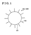
- Fig. 1 is a schematic view of the ferrous oxide (FeO) nanoparticle 100, 1200, or the Iron(II) oxide nanoparticle, according to the first and the second embodiments.
- the FeO nanoparticle 100, 1200 according to the first and the second embodiments possesses plural iron (Fe) atoms and plural oxygen (O) atoms and includes a ferrous oxide (FeO) core 101 having a ferrous oxide (FeO) structure, or a wüstite, as main component.
- the FeO nanoparticle 100, 1200 may include a surfactant 102 adhering to at least one atom composing the FeO core 101.
- Fig. 2A is a flowchart showing the method of manufacturing the FeO nanoparticle 100 according to the first embodiment.
- Fig. 2B is a schematic view drawing illustrating the method of manufacturing the FeO nanoparticle 100 according to the first embodiment.
- the method of manufacturing the FeO nanoparticle 100 according to the first embodiment and the method of manufacturing the FeO nanoparticle 100 in first to fifth practical examples according to the first embodiment use a method known as a liquid-phase method.
- an iron oxide 211 which is the basic material for forming the FeO core 101, an organic acid 212, and a first solvent 213 are mixed in a flask 210, for example, a three-necked flask or a four-necked flask.
- the iron oxide 211 are FeO, ⁇ -Fe 2 O 3 , ⁇ -Fe 2 O 3 , Fe 3 O 4 , and ⁇ -FeOOH.
- the organic acid 212 is the surfactant 102 that dissolves the iron oxide 211 and adheres to the surface of the FeO core 101. The surfactant 102 restrains the FeO nanoparticles 100 from clumping together and stabilizes the surface condition of the FeO nanoparticle 100.
- Examples of the organic acid 212 are a long-chain polyunsaturated fatty acid, for example, an oleic acid and a linoleic acid, and a saturated long chain fatty acid, for example, a stearic acid.
- the first solvent 213 is favorably a non-polar solvent having a boiling point equal to or higher than 210°C. Examples of the first solvent 213 are 1-octadecene and dodecane.
- a molar ratio between the organic acid 212 and the iron oxide 211 that are mixed in the flask 210 is obtained from experiences.
- the molar ratio here is the organic acid/the iron oxide.
- formed FeO nanoparticles 100 dissolve.
- a core for forming the FeO nanoparticle 100 may not be formed. Accordingly, favorable molar ratio (the organic acid/the iron oxide) between the organic acid 212 and the iron oxide 211 is a value between 6 and 100.
- next step S202 which serves as a water removing step, after the atmosphere in the flask 210 is substituted with an inactive gas 214, for example, argon or nitrogen, water in the solution In the flask 210 is removed by raising the temperature of the solution in the flask 210 to a first temperature.
- the first temperature is a temperature equal to or higher than the boiling point of water.
- the first temperature favorably is the temperature between 100°C and 130°C.
- the second temperature which is a temperature equal to or lower than the boiling point of the first solvent 213, is obtained from experiences. In a case where the second temperature is too low, the FeO core 101 may not be formed.
- the second temperature is a temperature in consideration of the temperature in which the FeO core 101 forms and the boiling point of the first solvent 213. Accordingly, the second temperature favorably is a temperature between 280°C and 360°C.
- the predetermined length of synthesis time is a sum of a first maintaining time and a second maintaining time.
- the first maintaining time is a length of time from a point in time at which the temperature of the solution in the flask 210 reaches the second temperature to a point in time at which the color of the solution changes.
- the second maintaining time is a length of time from the point in time at which the color of the solution changes to a point in time at which the churning is ended, in other words to the point in time at which the reaction is ended.
- the first maintaining time varies in accordance with the amount of the organic acid 212.
- the first maintaining time is a length of time from a point in time at which the temperature of the solution reaches the second temperature to a point in time at which the color of the solution changes from red to black.
- step S204 which serves as a particle extracting step, the reacted solution in which the FeO nanoparticles 100 are dispersed is displaced to a centrifuge tube 215 and with, for example, an ethanol or a hexane, and by using a centrifugal machine, unreacted substances are removed from the reacted solution through a refinement process so as to extract the FeO nanoparticles 100 In a paste form.
- the extracted FeO nanoparticles 100 may be dried into a powder form at this time.
- the particle diameter of the FeO nanoparticles 100 is measured by using, for example, a transmission electron microscope (TEM) or a scanning electron microscope (SEM), or by optical absorptiometry.
- TEM transmission electron microscope
- SEM scanning electron microscope
- the manufacturing apparatus 300 Includes a fuel gas source 301, a carrier gas source 302, mass flow controllers (MFC) 303 connected to the fuel gas source 301 and to the carrier gas source 302 via gas introduction pipes 304, and a chamber 305 connected to the gas introduction pipes 304.
- the chamber 305 includes shower plates 306 connected to the gas introduction pipes 304, heaters 307 positioned around the shower plates 306 and a base plate holder 308 for retaining a base plate 309.
- the fuel gas source 301 supplies a fuel gas containing, for example, alkane or the like aliphatic hydrocarbon or alcohol or the like aliphatic compound as a source of carbon for manufacturing the carbon nanotubes 402, 502, 1004.
- the carrier gas source 302 supplies a carrier gas containing argon, nitrogen, or the like inactive gas.
- the mass flow controllers (MFC) 303 control flow amounts of the fuel gas and the carrier gas so that a gas in mixture of the fuel gas and the carrier gas in a predetermined ratio Is supplied to the shower plates 306.
- the shower plates 306 evenly supplies the gas in mixture to the base plate 309 positioned at the base plate holder 308.
- the heaters 307 heat inside the chamber 305 so as to control the surface temperature of the base plate 309.
- the method of forming the carbon nanotube 402, 502, 1004 according to the first embodiment will be described next.
- the carbon nanotubes 402, 502, 1004 are formed with FeO nanoparticles 100 serving as catalysts being supported on the base plate 309, which is made of, for example, metal, ceramics, silicon, or a metallic foil.
- a catalyst supporting base plate 309a is produced.
- the FeO nanoparticles 100 are dispersed, for example, in hexane and the concentration of the FeO nanoparticles 100 in the liquid is controlled so that the absorbance of light becomes a predetermined value when measured by a colorimeter.
- the base plate 309 or alternatively a metallic full, is immersed in the liquid containing the FeO nanoparticles 100 being dispersed therein and pulled out of the liquid with a predetermined pull-out speed, In a case in which the pull-out speed is slow, the density of the FeO nanoparticles 100 being supported on the base plate is relatively increased.
- the density of the FeO nanoparticles 100 being supported on the base plate is relatively decreased.
- the catalyst supporting base plate 309a supporting the FeO nanoparticles 100 is produced.
- a liquid containing the FeO nanoparticles 100 dispersed therein may be sprayed on the base plate 309 or may be applied on the base plate 309 by spin coating to produce the catalyst supporting base plate 309a.
- the catalyst supporting base plate 309a supporting the FeO nanoparticle 100 is positioned at the base plate holder 308 in the chamber 305.
- the temperature inside the chamber 305 is heated to a predetermined temperature.
- the gas in mixture of the fuel gas and the carrier gas in the predetermined ratio is supplied to the catalyst supporting base plate 309a via the shower plates 306. While supplying the gas in mixture, the surface temperature of the catalyst supporting base plate 309a is controlled so as to manufacture, or form, the carbon nanotubes 402, 502, 1004 on the catalyst supporting base plate 309a.
- the FeO nanoparticle 100 are manufactured by using Fe 2 O 3 powder as the iron oxide 211, an oleic acid as the organic acid 212, and 1-octadecene as the first solvent 213.
- step S201 3 millimoles (mmol) of the iron oxide 211 (Fe 2 O 3 powder), 90mmol of the oleic acid, 20 milliliters (ml) of 1-octadecene are mixed in a flask 210, which is four-necked. The atmosphere in the flask 210 is then substituted with an argon gas for 60 minutes. After that, in step S202, the temperature of the solution in the flask 210 is raised to 130°C for 30 minutes and removed water in the solution.
- step S203 the temperature of the solution in the flask 210 is raised to 320°C by using a heater, for example, a mantle heater, and maintained at 320°C for eight hours of synthesis time while churning the solution In the flask 210 for reactions to occur.
- a heater for example, a mantle heater
- the temperature of the solution In the flask 210 is lowered to the room temperature and the reacted solution in which Fe nanoparticles are dispersed is removed from the flask 210.
- the first temperature which is 130°C, is raised so as to reach the second temperature, which is 320°C, by taking 20 minutes.
- step S204 in order to remove unreacted substances, the reacted solution is placed in a centrifuge tube 215 and centrifuged at the rotational speed of 1500 revolutions per minute (rpm) for 20 minutes. After that, a supernatant solution containing the Fe nanoparticles is separated and the supernatant solution, hexane, and ethanol are mixed in another centrifuge tube 215 in ratio of 1:1:2 and centrifuged at the rotational speed of 5800rpm for 30 minutes. The processes of separating the supernatant solution, of mixing the supernatant solution, hexane, and ethanol, and of centrigugation are repeated for three to four times and the precipitated Fe nanoparticles in paste form are extracted.
- rpm revolutions per minute
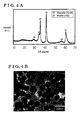
- Fig. 4B is a transmission electron microscope (TEM) image of the FeO nanoparticles 100 manufactured in the first practical example.
- the TEM image shows that the average particle diameter of the FeO nanoparticles 100 manufactured in the first practical example is 30nm.
- the carbon nanotubes 402 are formed by using the FeO nanoparticles 100 manufactured in the first practical example as catalysts.
- the FeO nanoparticles 100 are dispersed in hexane and the concentration of the FeO nanoparticles 100 in the liquid is controlled so that the absorbance of light becomes 0.74 when measured by the colorimeter (CO7500 manufactured by WPA) under the measurement condition of wavelength of 680nm.
- a silicon base plate (manufactured by SAMCO) is immersed In the liquid containing the FeO nanoparticles100 being dispersed therein, the liquid in which the concentration is controlled, and then the silicon base plate is pulled out of the liquid into air under the room temperature with a speed of 3 millimeters/minute. After that, the silicon base plate is dried naturally and hexane is evaporated. Accordingly, a catalyst supporting base plate 401 supporting the FeO nanoparticles 100 is produced.
- the catalyst supporting base plate 401 supporting the FeO nanoparticles 100 is arranged in the chamber 305 of the manufacturing apparatus 300 and then the chamber 305 is vacuumed until the pressure inside of the chamber 305 becomes 10 pascal (Pa).
- a nitrogen gas serving as the carrier gas is introduced into the chamber 305 at the flow rate of 2.5 liters/minute so as to control the pressure inside of the chamber 305 becomes 96 kilopascal (kPa).
- the surface temperature of the catalyst supporting base plate 401 is raised so as to reach 850°C by taking 10 minutes and an acethylene gas serving as the fuel gas is added to the nitrogen gas at the flow rate of 0.5 liters/minute for 25 minutes into the chamber 305.
- the carbon nanotubes 402 are formed on the catalyst supporting base plate 401.
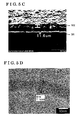
- Fig. 4C is a scanning electron microscope (SEM) image of the carbon nanotubes 402 formed by using the catalyst supporting base plate 401 supporting the FeO nanoparticles 100 manufactured in the first practical example.
- the length of the carbon nanotubes 402 formed on the catalyst supporting base plate 401 supporting the FeO nanoparticles 100 manufactured in the first practical example having the average particle diameter of 30nm is approximately 38.7 micrometers ( ⁇ m).
- Fig. 4D is a TEM image of the carbon nanotube 402 formed by using the catalyst supporting base plate 401 supporting the FeO nanoparticles 100 manufactured in the first practical example.
- the outer diameter of the carbon nanotube 402 is approximately 29nm and number of layers of the carbon nanotube 402 is approximately 26.
- the outer diameter of the carbon nanotube 402, which is approximately 29nm, is approximately the same as the average particle diameter of the FeO nanoparticle 100 that served as the catalyst, which is approximately 30nm.
- Fe nanoparticles are manufactured with same materials, in other words with the Fe 2 O 3 powder, the oleic acid, and 1-octadecene, and under same manufacturing condition as in the first practical example except in the synthesis time, which is changed to five hours, so as to manufacture the Fe nanoparticles having smaller particle diameter compared to that of the first practical example.
- the temperature of the solution in the flask 210 is lowered to the room temperature and the reacted solution in which Fe nanoparticles are dispersed is removed from the flask 210.
- Precipitated Fe nanoparticles are extracted through a refinement process for the reacted solutions by using the same method as the method used in the first practical example.
- the first temperature which is 130°C
- the second temperature which is 320°C, by taking 20 minutes.
- Fig. 5A is an X-ray diffraction pattern of the extracted Fe nanoparticles for the first comparison example. Diffraction peaks due to the Fe 3 O 4 structures, in other words due to the magnetites, which are indicated with M in Fig. 5A , are recognized in the X-ray diffraction pattern. On the other hand, the diffraction peak due to the FeO structure, in other words due to the wüstite, is scarcely recognized. Therefore, the Fe nanoparticles extracted in the first comparison example are recognized as the Fe 3 O 4 nanoparticles.
- Fig. 5B is a TEM image of the Fe 3 O 4 nanoparticles manufactured in the first comparison example.
- the TEM image shows that the average particle diameter of the Fe 3 O 4 nanoparticles manufactured in the first comparison example is 15nm.
- the catalyst supporting base plate 501 supporting the Fe 3 O 4 nanoparticles manufactured in the first comparison example is produced by using the same method as the method used in the first practical example.
- the carbon nanotubes 502 are formed by using the catalyst supporting base plate 501 under the same conditions as the conditions defined in the first practical example.
- Fig. 5C is a SEM image of the carbon nanotubes 502 formed by using the catalyst supporting base plate 501 supporting the Fe 3 O 4 nanoparticles manufactured in the first comparison example.
- the length of the carbon nanotubes 502 formed on the catalyst supporting base plate 501 supporting the Fe 3 O 4 nanoparticles manufactured in the first comparison example having an average particle diameter of 15nm is approximately 11.6 ⁇ m.
- Fig. 5D is a TEM image of the carbon nanotube 502 formed by using the Fe 3 O 4 nanoparticles manufactured in the first comparison example.
- the outer diameter of the carbon nanotube 502 is approximately 16nm and number of layers of the carbon nanotube 502 is 11.
- the outer diameter of the carbon nanotube 402, which is approximately 16nm, is approximately the same as the average particle diameter of Fe 3 O 4 nanoparticle that served as the catalyst, which is approximately 15nm.
- the Fe nanoparticle having approximately 30nm particle diameter manufactured in the first practical example is the FeO nanoparticle 100 with the FeO structure, or the wüstite, as main component
- the Fe nanoparticle having approximately 15nm particle diameter manufactured in the first comparison example is the Fe 3 O 4 nanoparticle with the Fe 3 O 4 structure, or the magnetite, as main component.
- the results lead to a recognition that the Fe nanoparticle forms the FeO structure (the wüstite), or the Fe 3 O 4 structure (the magnetite), depending on the particle size of the Fe nanoparticle.
- the growth performance of the carbon nanotubes 402 formed by using the catalyst supporting base plate 401 supporting the FeO nanoparticles 100 in which the length of the carbon nanotubes 402 is approximately 38.7 ⁇ m is approximately three times greater than the growth performance of the carbon nanotubes 502 formed by using the catalyst supporting base plate 501 supporting the Fe 3 O 4 nanoparticles in which the length of the carbon nanotubes 502 is approximately 11.6 ⁇ m.
- the results lead to a recognition that the Fe nanoparticles with the FeO structure as the main component, in other words the FeO nanoparticle 100, enhances the growth performance of carbon nanotubes.
- a second comparison example for comparing with the practical examples according to this disclosure, and a second practical example, a third practical example, and a fourth practical examples according to this disclosure will be described below.
- Fe nanoparticles having different particle diameters are manufactured by controlling the molar ratio between the organic acid 212, which is an oleic acid, and the iron oxide 211, which is an Fe 2 O 3 powder, and by controlling synthesis time for each example.
- the method of manufacturing the Fe nanoparticle for each example is identical to the method used in the first practical example except in the molar ratio between the organic acid 212, which is an oleic acid, and the iron oxide 211, which is the Fe 2 O 3 powder, and in synthesis time. Accordingly, repetitive descriptions will be omitted.
- Fig. 6A is an X-ray diffraction pattern 601 of the Fe nanoparticles manufactured in the second comparison example
- Fig. 6B is a TEM image 602 of the Fe nanoparticles manufactured in the second comparison example. From the X-ray diffraction pattern 601 and the TEM image 602, the Fe nanoparticles manufactured in the second comparison example are recognized as Fe 3 O 4 nanoparticles having the Fe 3 O 4 structures as main components.
- the average particle diameter of the Fe 3 O 4 nanoparticles is 14nm where the particle diameter distribution of the Fe 3 O 4 nanoparticles is In a range of 12nm to 15nm.
- Fig. 7A is an X-ray diffraction pattern 701 of the Fe nanoparticles manufactured in the second practical example
- Fig. 7B is a TEM image 702 of the Fe nanoparticles manufactured in the second practical example. From the X-ray diffraction pattern 701 and the TEM image 702, the Fe nanoparticles. manufactured in the second practical example are recognized as the FeO nanoparticles 100 having FeO structures as main components.
- the average particle diameter of the FeO nanoparticles 100 is 20nm where the particle diameter distribution of the FeO nanoparticles 100 is in a range of 18nm to 21 nm.
- the third practical example will be described below.
- the molar ratio between the oleic acid and the Fe 2 O 3 powder is controlled to 30 and the synthesis time is controlled to seven hours for manufacturing the Fe nanoparticles.
- Fig, 8A is an X-ray diffraction pattern 801 of the Fe nanoparticles manufactured in the third practical example
- Fig. 8B is a TEM image 802 of the Fe nanoparticles manufactured in the third practical example. From the X-ray diffraction pattern 801 and the TEM Image 802, the Fe nanoparticles manufactured in the third practical example are recognized as FeO nanoparticles 100 having FeO structures as main components.
- the average particle diameter of the FeO nanoparticles 100 is 28nm where the particle diameter distribution of the FeO nanoparticles 100 is in a range of 26nm to 29nm.
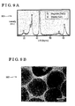
- Fig. 9A is an X-ray diffraction pattern 901 of the Fe nanoparticles manufactured in the fourth practical example
- Fig. 9B is a TEM image 902 of the Fe nanoparticles manufactured in the fourth practical example. From the X-ray diffraction pattern 901 and the TEM image 902, the Fe nanoparticles manufactured in the fourth practical example are recognized as FeO nanoparticles 100 having FeO structures as main components.
- the average particle diameter of the FeO nanoparticles is 45nm where the particle diameter distribution of the FeO nanoparticles is in a range of 43nm to 46nm.
- Table 1 Organic acid/Iron oxide (Molar ratio) First maintaining time (Hour) Second maintaining time (Hour) Synthesis time (Hour) Average particle diameter (nm) Particle diameter distribution (nm) Main component Second comparison example 15 1 3 4 14 12 to 15 Fe 3 O 4 First comparison Example 6 1 4 5 15 - Fe 3 O 4 Second practical example 18 2 3 5 20 18 to 21 FeO Third practical example 30 4 3 7 28 26 to 29 FeO First practical example 30 4 4 8 30 - FeO Fourth practical example 45 6 4 10 45 43 to 46 FeO
- the particle diameter of the Fe nanoparticle is favorably equal to or more than 17nm so as to form the FeO nanoparticle 100.
- the particle diameter that is equal to or more than 18nm is more favorable. Further, the particle diameter that is equal to or more than 20nm is more favorable.
- the concentration of FeO nanoparticles 100 is controlled so that the absorbance of light of the liquid in which the FeO nanoparticles 100 manufactured in the first practical example are dispersed becomes equal to or greater than 2.00 so as to produce the catalyst supporting base plate 1003.
- the concentration of FeO nanoparticles 100 is controlled so that the absorbance of light of the liquid in which the FeO nanoparticles 100 manufactured in the first practical example are dispersed becomes equal to or greater than 2.00 so as to produce the catalyst supporting base plate 1003.
- equal to or more than four times the amount of the FeO nanoparticles 100 per unit area is supported on the catalyst supporting base plate 1003 compared to the first practical example.
- carbon nanotubes 1004 are formed by using the mentioned catalyst supporting base plate 1003 and by using the method identical to that of the first practical example.
- Fig. 10A is a SEM image 1001 of the carbon nanotubes 1004 formed in the fifth practical example, in which the carbon nanotubes 1004 are formed by using the catalyst supporting base plate 1003 supporting the FeO nanoparticles 100 having the average particle diameter of 30nm manufactured in the fifth practical example.
- Fig. 10B is a TEM image 1002 of the mentioned carbon nanotube 1004.
- the SEM image 1001 shows that the length of the carbon nanotubes 1004 formed on the catalyst supporting base plate 1003 supporting the FeO nanoparticles 100 having the average particle diameter of 30nm is approximately 99.5 ⁇ m.
- the TEM image 1002 shows that the outer diameter of the carbon nanotube 1004 is approximately 32nm and number of layers of the carbon nanotube 1004 is 27.
- the length of the carbon nanotubes 1004 formed on the catalyst supporting base plate 1003 supporting the FeO nanoparticles 100 having average particle diameter of 30nm manufactured in the fifth practical example is approximately 2.6 times longer than the length of the carbon nanotubes 402 formed in the first practical example.
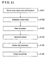
- step S1101 an iron oxide 211, which is the basic material for forming the FeO core 101, an organic acid 212, and a first solvent 213 are mixed in a flask 210.
- the iron oxide 211, the organic acid 212, and the first solvent 213 are identical to those used In the first embodiment and the descriptions in detail of those will be omitted.
- the examples of the second solvent 1201 are oleylamine, stearylamine, 1-hexadecanol, 1-octadecanol, and 1, 2-hexadecanediol.
- the second solvent 1201 reacts with the surfactant 102, which is the organic acid 212, adhered to the FeO core 101 so that the FeO cores 101 removed of the surfactant 102 agglomerate and fuse with each other.
- the particle diameter of the FeO nanoparticles 1200 manufactured by adding the second solvent 1201 becomes larger compared to the particle diameter of FeO nanoparticles manufactured by not adding the second solvent 1201.
- the second solvent 1201 is a solvent for increasing the particle diameter of the FeO nanoparticles. Accordingly, in the second embodiment, the second solvent 1201 may be referred to as a particle diameter increasing solvent.
- step S1105 which serves as a second temperature maintaining step, the second temperature of the solution in the flask 210 is maintained and the churning is continued for a predetermined length of synthesis time. After that, the temperature of the solution in the flask 210 is lowered to a room temperature and the reacted solution in which the FeO nanoparticles 1200 are dispersed is removed from the flask 210.
- step S1101 3mmol of the iron oxide 211 (Fe 2 O 3 powder), 90mmol of the oleic acid, 20ml of 1-octadecene are mixed in a flask 210, which is four-necked. The atmosphere in the flask 210 is then substituted with an argon gas for 60 minutes. After that, in step S1102, the temperature of the solution in the flask 210 is raised to 130°C, which is the first temperature, for 30 minutes and removed water in the solution.
- step S1105 the temperature of the solution is maintained at 320°C for fifteen hours of synthesis time while churning the solution in the flask 210 for reactions to occur. Then, the temperature of the solution is lowered to the room temperature and the reacted solution in which Fe nanoparticles are dispersed is removed from the flask 210.
- the first temperature which is 130°C, is raised so as to reach the second temperature, which is 320°C, by taking 20 to 30 minutes.
- step S1106 In order to remove unreacted substances, the reacted solution is placed in a centrifuge tube 215 and centrifuged at the rotational speed of 1500rpm for 20 minutes. After that, a supernatant solution containing the Fe nanoparticles is separated and the supernatant solution, hexane, and ethanol are mixed in another centrifuge tube 215 in ratio of 1:1:2 and centrifuged at the rotational speed of 5800rpm for 30 minutes. The processes of separating the supernatant solution, of mixing the supernatant solution, hexane, and ethanol, and of centrigugation are repeated for three to four times and the precipitated Fe nanoparticles in paste form are extracted.
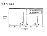
- Fig. 13A is an X-ray diffraction pattern of the Fe nanoparticles for the sixth practical example.
- Relatively weak diffraction peaks due to the Fe 3 O 4 structures, in other words due to the magnetites, which are indicated with M in Fig. 13A and relatively strong diffraction peaks due to the ferrous oxide (FeO) structures, in other words due to the wüstites, which are indicated with W in Fig. 13A , are recognized in the X-ray diffraction pattern. Therefore, a large amount of the Fe nanoparticles extracted in the sixth practical example is recognized as the FeO nanoparticles 1200.
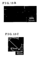
- Fig. 13B is a TEM image of the FeO nanoparticles 1200 manufactured in the sixth practical example.
- Fig. 13C is another TEM image of the FeO nanoparticle 1200 manufactured in the sixth practical example having the largest particle diameter.
- the TEM images show that the average particle diameter of the FeO nanoparticles 1200 manufactured in the sixth practical example is 75nm.
- the particle diameter distribution of the FeO nanoparticles 1200 is in a range of 68nm to 83nm.
- Fig. 13C shows that the FeO nanoparticle 1200 having the largest particle diameter is 87nm in particle diameter.
- the FeO nanoparticles 1200 having larger average particle diameter of 75nm are manufactured compared to the FeO nanoparticles 100 having average particle diameter of 30nm manufactured in the first practical example.
- the FeO nanoparticles 1200 and the FeO nanoparticles 100 are manufactured under common conditions except in that the second solvent 1201 is added in the sixth practical example.
- the FeO nanoparticles 1200 are dispersed in hexane and the concentration of the FeO nanoparticles 1200 in the liquid is controlled so that the absorbance of light becomes 0.74 when measured by a colorimeter (CO7500 manufactured by WPA) under the measurement conditions of wavelength of 680nm.
- a silicon base plate (manufactured by SAMCO) is immersed in the liquid containing the FeO nanoparticles 1200 being dispersed therein, the liquid in which the concentration is controlled, and then the silicon base plate is pulled out of the liquid into air under the room temperature with a speed of 3 millimeters/minute. After that, the silicon base plate is dried naturally and hexane is evaporated. Accordingly, a catalyst supporting base plate 1301 supporting the FeO nanoparticles 1200 is produced.
- the catalyst supporting base plate 1301 supporting the FeO nanoparticles 1200 is arranged in the chamber 305 of the manufacturing apparatus 300 and then the chamber 305 is vacuumed until the pressure inside the chamber 305 becomes 10Pa.
- a nitrogen gas serving as the carrier gas is introduced into the chamber 305 at the flow rate of 2.5 liters/minute so as to adjust the pressure inside the chamber 305 becomes 96kPa.
- the surface temperature of the catalyst supporting base plate 1301 is raised so as to reach 850°C by taking 10 minutes and an acethylene gas serving as the fuel gas is added to the nitrogen gas at the flow rate of 0.5 liters/minute for 25 minutes into the chamber 305.
- the carbon nanotubes 1302 are formed on the catalyst supporting base plate 1301.
- Fig. 13D is a SEM image of the carbon nanotubes 1302 formed by using the catalyst supporting base plate 1301 supporting the FeO nanoparticles 1200 manufactured in the sixth practical example.
- the length of the carbon nanotubes 1302 formed on the catalyst supporting base plate 1301 supporting the FeO nanoparticles 1200 manufactured in the sixth practical example having the average particle diameter of 75nm is approximately 106 ⁇ m.
- Fig. 13E is a TEM image of the carbon nanotube 1302 formed by using the catalyst supporting base plate 1301 supporting the FeO nanoparticles 1200 manufactured in the sixth practical example.
- the outer diameter of the carbon nanotube 1302 is approximately 69nm, which is close to the average particle diameter of the FeO nanoparticle 1200 manufactured in the sixth practical example that served as the catalyst, which is 75nm.
- the growth performance of the carbon nanotubes 1302 formed by using the catalyst supporting base plates 1301 supporting the FeO nanoparticles 1200 manufactured in the sixth practical example in which the length of the carbon nanotubes 1302 is approximately 106 ⁇ m with the growth performance of the carbon nanotubes 402 formed in the first practical example in which the length of the carbon nanotubes 402 is approximately 38.7 ⁇ m
- the growth performance of the carbon nanotubes 1302 according to the sixth practical example is approximately three times greater than the growth performance of the carbon nanotubes 402 according to the first practical example.
- the FeO nanoparticles 1200 are manufactured by using the same materials used in the sixth practical example that are the Fe 2 O 3 powder, the oleic acid, 1-octadecene, and oleylamine and under almost identical manufacturing condition, except that the oleylamine is added to the solution from the beginning that is at the same time as step S1101.
- the temperature of the solution is lowered to the room temperature and the reacted solution in which Fe nanoparticies are dispersed is removed from the flask 210.
- the reacted solution is refined in the same method that is used in the sixth practical example so as to extract the precipitated Fe nanoparticles.
- Fig. 14B is a TEM image of the FeO nanoparticles 1200 manufactured in the seventh practical example.
- the TEM image shows that the average particle diameter of the FeO nanoparticles 1200 manufactured in the seventh practical example is 34nm.
- the particle diameter distribution of the FeO nanoparticles 1200 is in a range of 23nm to 43nm.
- the average particle diameter of the FeO nanoparticles 1200 manufactured in the seventh practical example, which is 34nm, is larger than that of the FeO nanoparticles 100 manufactured in the first practical example, which is 30nm, but is smaller than that of the FeO nanoparticles 1200 manufactured in the sixth practical example, which is 75nm.
- the reason is because the oleyleamine and the oleic acid, which serves as the organic acid 212, neutralize each other when the oleyleamine is added from the beginning and the iron oxide 211 (Fe 2 O 3 ) is not smoothly dissolved by the oleic acid, which serves as the organic acid 212.
- FeO nanoparticles 1200 are manufactured by using the same materials used in the sixth practical example that are Fe 2 O 3 powder as the iron oxide 211, the oleic acid as the organic acid 212, 1-octadecene as the first solvent 213, and oleylamine as the second solvent 1201.
- the amount of oleylamine is reduced to 0.5 times the amount that is used in the sixth practical example and the synthesis time is defined at ten hours.
- step S1101 3mmol of the iron oxide 211 (Fe 2 O 3 powder), 90mmol of the oleic acid, 20ml of 1-octadecene are mixed in a flask 210, which is four-necked. The atmosphere in the flask 210 is then substituted with an argon gas for 60 minutes. After that, in step S1102, the temperature of the solution in the flask 210 is raised to 130°C, which is the first temperature, for 30 minutes and removed water in the solution.
- step S1103 the temperature of the solution in the flask 210 is raised to 320°C, which is the second temperature, by using a heater, for example, a mantle heater, while churning the solution in the flask 210.
- step S1104 while the temperature of the solution in the flask 210 is maintained at 320°C and while churning is continued, 9mmol of oleylamine is added to the solution in the flask 210 after 30 minutes has elapsed from a point in time at which the temperature of the solution in the flask 210 has reached 320°C.
- step S1105 the temperature of the solution is maintained at 320°C for ten hours of synthesis time while churning the solution in the flask 210 for reactions to occur. Then, the temperature of the solution is lowered to the room temperature and the reacted solution in which Fe nanoparticles are dispersed is removed from the flask 210.
- the first temperature which is 130°C, is raised so as to reach the second temperature, which is 320°C, by taking 20 to 30 minutes.
- step S1106 in order to remove unreacted substances, the reacted solution is placed in a centrifuge tube 215 and centrifuged at the rotational speed of 1500rpm for 20 minutes. After that, a supernatant solution containing the Fe nanoparticles is separated and the supernatant solution, hexane, and ethanol are mixed in another centrifuge tube 215 in ratio of 1:1:2 and centrifuged at the rotational speed of 5800rpm for 30 minutes. The processes of separating the supernatant solution, of mixing the supernatant solution, hexane, and ethanol, and of centrigugation are repeated for three to four times and the precipitated Fe nanoparticles in paste form are extracted.
- Fig. 15A is an X-ray diffraction pattern of the Fe nanoparticies for the eighth practical example.
- Relatively weak diffraction peaks due to the Fe 3 O 4 structures, in other words due to the magnetites, which are indicated with M in Fig. 15A and relatively strong diffraction peaks due to the ferrous oxide (FeO) structures, in other words due to the wüstites, which are indicated with W in Fig. 15A , are recognized in the X-ray diffraction pattern. Therefore, a large amount of the Fe nanoparticles extracted in the eighth practical example is recognized as the FeO nanoparticles 1200.
- Fig. 15B is a TEM image of the FeO nanoparticles 1200 manufactured in the eighth practical example.
- the TEM image shows that the average particle diameter of the FeO nanoparticle 1200 manufactured in the eighth practical example is 40nm.
- the particle diameter distribution of the FeO nanoparticles 1200 is in a range of 30nm to 52nm.
- the average particle diameter of the FeO nanoparticles 1200 manufactured in the eighth practical example, which is 40nm is smaller than that of the FeO nanoparticles 1200 manufactured in the sixth practical example, which is 75nm, but is larger than that of the FeO nanoparticles 100 manufactured in the first practical example, which is 30nm. Accordingly, the effectiveness of the oleylamine as the particle diameter increasing solvent is recognized.
- Table 2 summarizes the results of the practical examples and comparison examples.
- a shell layer for example, an alloy of Fe and Ti, for enhancing the catalyst performance for forming a carbon nanotube may be formed around the FeO core 101.
- a method of manufacturing a ferrous oxide nanoparticle (100, 1200) includes a water removing step (S202, S1102) raising temperature of a solution containing an iron oxide (211), an organic acid (212) dissolving the iron oxide (211), and a first solvent (213) to a first temperature and removing water in the solution, a second temperature maintaining step (S203, S1103, S1105) raising the first temperature to a second temperature and maintaining the second temperature, and a particle extracting step (S204, S1106) extracting the ferrous oxide nanoparticle (100, 1200) from the solution after the second temperature maintaining step (S203, S1103, S1105).
Landscapes
- Chemical & Material Sciences (AREA)
- Engineering & Computer Science (AREA)
- Organic Chemistry (AREA)
- Materials Engineering (AREA)
- Nanotechnology (AREA)
- Chemical Kinetics & Catalysis (AREA)
- Crystallography & Structural Chemistry (AREA)
- Physics & Mathematics (AREA)
- Condensed Matter Physics & Semiconductors (AREA)
- General Physics & Mathematics (AREA)
- Inorganic Chemistry (AREA)
- Manufacturing & Machinery (AREA)
- Composite Materials (AREA)
- Life Sciences & Earth Sciences (AREA)
- Environmental & Geological Engineering (AREA)
- General Life Sciences & Earth Sciences (AREA)
- Geochemistry & Mineralogy (AREA)
- Geology (AREA)
- Mechanical Engineering (AREA)
- Metallurgy (AREA)
- Carbon And Carbon Compounds (AREA)
- Catalysts (AREA)
- Compounds Of Iron (AREA)
- Dispersion Chemistry (AREA)
Abstract
Description
- This disclosure generally relates to a method of manufacturing a ferrous oxide (FeO) nanoparticle, a method of forming a carbon nanotube, and the ferrous oxide (FeO) nanoparticle.
- A technology for manufacturing a carbon nanotube by chemically manufacturing an Fe nanoparticle and using the Fe nanoparticle as a catalyst is known. For example,
JP2009-215146A JP2009-227470A - A need thus exists for a method of manufacturing a ferrous oxide (FeO) nanoparticle by using a liquid-phase method. Furthermore, a need exists for manufacturing a carbon nanotube having large outer diameter while enhancing growth potential of the carbon nanotube by using the ferrous oxide (FeO) nanoparticle.
- A method of manufacturing a ferrous oxide nanoparticle includes a water removing step raising temperature of a solution containing an iron oxide, an organic acid dissolving the iron oxide, and a first solvent to a first temperature and removing water in the solution, a second temperature maintaining step raising the first temperature to a second temperature and maintaining the second temperature, and a particle extracting step extracting the ferrous oxide nanoparticle from the solution after the second temperature maintaining step.
- Accordingly, the ferrous oxide (FeO) nanoparticle, or the iron(II) oxide nanoparticle, is manufactured by using a liquid-phase method, Using the FeO nanoparticle manufactured as such as a catalyst results in manufacturing a carbon nanotube having a large outer diameter while enhancing growth potential of the carbon nanotube.
- According to another aspect of this disclosure, the second temperature in the method of manufacturing the ferrous oxide nanoparticle is maintained for a length of time in which a size of a particle extracted after the second temperature maintaining step becomes equal to or larger than 17 nanometers in diameter.
- Accordingly, the ferrous oxide (FeO) nanoparticle is manufactured by using a liquid-phase method. Using the FeO nanoparticle manufactured as such as the catalyst results in manufacturing a carbon nanotube having a large outer diameter while enhancing growth potential of the carbon nanotube.
- According to further aspect of this disclosure, the second temperature maintaining step in the method of manufacturing the ferrous oxide nanoparticle includes a step of adding a second solvent reacting with the organic acid.
- Accordingly, the ferrous oxide (FeO) nanoparticle is manufactured by using a liquid-phase method. Using the FeO nanoparticle manufactured as such as the catalyst results in manufacturing a carbon nanotube having a large outer diameter while enhancing growth potential of the carbon nanotube.
- According to another aspect of this disclosure, the organic acid is an oleic acid and the second solvent is an oleylamine in the method of manufacturing the ferrous oxide nanoparticle.
- Accordingly, the ferrous oxide (FeO) nanoparticle is manufactured by using a liquid-phase method. Using the FeO nanoparticle manufactured as such as the catalyst results in manufacturing a carbon nanotube having a large outer diameter while enhancing growth potential of the carbon nanotube.
- According to further aspect of this disclosure, a method of forming a carbon nanotube includes the steps of producing a catalyst supporting base plate supporting a ferrous oxide nanoparticle on a base plate, the ferrous oxide nanoparticle manufactured by using a liquid-phase method and having a ferrous oxide structure as main component and having a particle size equal to or larger than 17 nanometers in diameter, and of forming a carbon nanotube on the catalyst supporting base plate.
- Using the ferrous oxide (FeO) nanoparticle manufactured by using a liquid-phase method and having a ferrous oxide (FeO) structure as main component and having a particle size equal to or larger than 17 nanometers in diameter as a catalyst results in manufacturing a carbon nanotube having a large outer diameter while enhancing growth potential of the carbon nanotube.
- According to another aspect of this disclosure, the ferrous oxide nanoparticle in the method of forming the carbon nanotube is formed by a method of manufacturing a ferrous oxide nanoparticle including a water removing step raising temperature of a solution containing an iron oxide, an organic acid dissolving the iron oxide, and a first solvent to a first temperature and removing water in the solution, a second temperature maintaining step raising the first temperature to a second temperature and maintaining the second temperature, and a particle extracting step extracting the ferrous oxide nanoparticle from the solution after the second temperature maintaining step.
- Accordingly, the ferrous oxide (FeO) nanoparticle is manufactured by using a liquid-phase method. Using the FeO nanoparticle manufactured by using the liquid-phase method as described above and having the ferrous oxide structure as main component and the particle size equal to or larger than 17 nanometers in diameter as the catalyst results in manufacturing a carbon nanotube having a large outer diameter while enhancing growth potential of the carbon nanotube.
- According to further aspect of this disclosure, a ferrous oxide nanoparticle is manufactured by using a liquid-phase method, the ferrous oxide nanoparticle having a ferrous oxide structure as main component and having a particle size equal to or larger than 17 nanometers in diameter.
- Using the ferrous oxide (FeO) nanoparticle manufactured by using a liquid-phase method and having the ferrous oxide (FeO) structure as main component and the particle size equal to or larger than 17 nanometers in diameter as the catalyst results in manufacturing a carbon nanotube having a large outer diameter while enhancing growth potential of the carbon nanotube.
- According to another aspect of this disclosure, the ferrous oxide nanoparticle is manufactured by using the liquid-phase method including a water removing step raising temperature of a solution containing an iron oxide, an organic acid dissolving the iron oxide, and a first solvent to a first temperature and removing water in the solution, a second temperature maintaining step raising the first temperature to a second temperature and maintaining the second temperature, and a particle extracting step extracting the ferrous oxide nanoparticle from the solution after the second temperature maintaining step.
- Accordingly, the ferrous oxide (FeO) nanoparticle having the ferrous oxide (FeO) structure as main component and the particle size equal to or larger than 17 nanometers in diameter is manufactured by using a liquid-phase method. Using the FeO nanoparticle manufactured as such as the catalyst results in manufacturing a carbon nanotube having a large outer diameter while enhancing growth potential of the carbon nanotube.
- The foregoing and additional features and characteristics of this disclosure will become more apparent from the following detailed description considered with the reference to the accompanying drawings, wherein:
-
Fig. 1 is a schematic view of a ferrous oxide (FeO) nanoparticle according to a first and a second embodiments; -
Fig. 2A is a flowchart showing the method of manufacturing the FeO nanoparticle according to the first embodiment; -
Fig. 2B is a schematic view drawing illustrating the method of manufacturing the FeO nanoparticle according to the first embodiment; -
Fig. 3 is a schematic view drawing illustrating a carbon nanotube manufacturing apparatus for use in the method of manufacturing the FeO nanoparticle, the method of forming the carbon nanotube, and the FeO nanoparticle according to the first embodiment; -
Fig. 4A is an X-ray diffraction pattern for a first practical example; -
Fig. 4B is a transmission electron microscope image of the FeO nanoparticles manufactured in the first practical example; -
Fig. 4C is a scanning electron microscope image of the carbon nanotubes formed in the first practical example; -
Fig. 4D is a transmission electron microscope image of carbon nanotube formed in the first practical example; -
Fig. 5A is an X-ray diffraction pattern for a first comparison example; -
Fig. 5B is a transmission electron microscope image of Fe3O4 nanoparticles manufactured in the first comparison example; -
Fig. 5C is a scanning electron microscope image of carbon nanotubes formed in the first comparison example; -
Fig. 5D is a transmission electron microscope image of the carbon nanotube formed in the first comparison example; -
Fig. 6A is an X-ray diffraction pattern for a second comparison example; -
Fig. 6B is a transmission electron microscope image of Fe nanoparticles manufactured in the second comparison example; -
Fig. 7A is an X-ray diffraction pattern for a second practical example; -
Fig. 7B is a transmission electron microscope image of Fe nanoparticles manufactured in the second practical example; -
Fig. 8A is an X-ray diffraction pattern for a third practical example; -
Fig. 8B is a transmission electron microscope image of Fe nanoparticles manufactured in the third practical example; -
Fig. 9A is an X-ray diffraction pattern for a fourth practical example; -
Fig. 9B is a transmission electron microscope image of Fe nanoparticles manufactured in the fourth practical example; -
Fig. 10A is a scanning electron microscope image of carbon nanotubes formed in a fifth practical example; -
Fig. 10B is a transmission electron microscope image of the carbon nanotube formed in the fifth practical example; -
Fig. 11 is a flowchart showing the method of manufacturing the FeO nanoparticle according to a second embodiment; -
Fig. 12 is a schematic view drawing illustrating the method of manufacturing the FeO nanoparticles according to the second embodiment; -
Fig. 13A is an X-ray diffraction pattern for a sixth practical example; -
Fig. 13B is a transmission electron microscope image of FeO nanoparticles manufactured in the sixth practical example; -
Fig. 13C is another transmission electron microscope image of the FeO nanoparticle manufactured in the sixth practical example; -
Fig. 13D is a scanning electron microscope image of carbon nanotubes formed in the sixth practical example; -
Fig. 13E is a transmission electron microscope image of the carbon nanotube formed in the sixth practical example; -
Fig. 14A is an X-ray diffraction pattern for a seventh practical example; -
Fig. 14B is a transmission electron microscope image of the FeO nanoparticles manufactured in the seventh practical example; -
Fig. 15A is an X-ray diffraction pattern for an eighth practical example; and -
Fig. 15B is a transmission electron microscope image of the FeO nanoparticles manufactured in the eighth practical example. - A method of manufacturing a ferrous oxide (FeO)
nanoparticle carbon nanotube nanoparticle nanoparticle carbon nanotube nanoparticle - The method of manufacturing the ferrous oxide (FeO)
nanoparticle 100, the method of forming thecarbon nanotube nanoparticle 100 according to a first embodiment will be described.Fig. 1 is a schematic view of the ferrous oxide (FeO)nanoparticle FeO nanoparticle core 101 having a ferrous oxide (FeO) structure, or a wüstite, as main component. TheFeO nanoparticle surfactant 102 adhering to at least one atom composing theFeO core 101. - The method of manufacturing the ferrous oxide (FeO)
nanoparticle 100 according to a first embodiment will be described first.Fig. 2A is a flowchart showing the method of manufacturing theFeO nanoparticle 100 according to the first embodiment.Fig. 2B is a schematic view drawing illustrating the method of manufacturing theFeO nanoparticle 100 according to the first embodiment. The method of manufacturing theFeO nanoparticle 100 according to the first embodiment and the method of manufacturing theFeO nanoparticle 100 in first to fifth practical examples according to the first embodiment use a method known as a liquid-phase method. - In step S201, an
iron oxide 211, which is the basic material for forming theFeO core 101, anorganic acid 212, and a first solvent 213 are mixed in aflask 210, for example, a three-necked flask or a four-necked flask. Examples of theiron oxide 211 are FeO, α-Fe2O3, γ-Fe2O3, Fe3O4, and α-FeOOH. Theorganic acid 212 is thesurfactant 102 that dissolves theiron oxide 211 and adheres to the surface of theFeO core 101. Thesurfactant 102 restrains theFeO nanoparticles 100 from clumping together and stabilizes the surface condition of theFeO nanoparticle 100. Examples of theorganic acid 212 are a long-chain polyunsaturated fatty acid, for example, an oleic acid and a linoleic acid, and a saturated long chain fatty acid, for example, a stearic acid. The first solvent 213 is favorably a non-polar solvent having a boiling point equal to or higher than 210°C. Examples of the first solvent 213 are 1-octadecene and dodecane. - A molar ratio between the
organic acid 212 and theiron oxide 211 that are mixed in theflask 210 is obtained from experiences. The molar ratio here is the organic acid/the iron oxide. In a case where the amount of theorganic acid 212 is too large relative to the amount of theiron oxide 211, formedFeO nanoparticles 100 dissolve. In a case where the amount of theorganic acid 212 is too small relative to the amount of theiron oxide 211, a core for forming theFeO nanoparticle 100 may not be formed. Accordingly, favorable molar ratio (the organic acid/the iron oxide) between theorganic acid 212 and theiron oxide 211 is a value between 6 and 100. In addition, the amount of the first solvent 213 favorably is an amount forming a solution having a concentration that does not affect the reaction, For example, in a case where the amount of the first solvent 213 is too large relative to the amount of theiron oxide 211 or to the amount of theorganic acid 212, the core for forming theFeO nanoparticle 100 may not be formed. - In the next step S202, which serves as a water removing step, after the atmosphere in the
flask 210 is substituted with aninactive gas 214, for example, argon or nitrogen, water in the solution In theflask 210 is removed by raising the temperature of the solution in theflask 210 to a first temperature. The first temperature is a temperature equal to or higher than the boiling point of water. The first temperature favorably is the temperature between 100°C and 130°C. - In step S203, which serves as a second temperature maintaining step, the temperature of the solution in the
flask 210 is raised from the first temperature to a second temperature while churning the solution in theflask 210. The second temperature is maintained and the churning is continued for a predetermined length of synthesis time. Theflask 210 may be configured with a condenser attached to an upper portion of theflask 210 so as to cool the evaporating first solvent 213 and so as to make the first solvent 213 reflux Into theflask 210 during this period. After that, the temperature of the solution in theflask 210 is lowered to a room temperature and a reacted solution in which theFeO nanoparticles 100 are dispersed is removed from theflask 210. - The second temperature, which is a temperature equal to or lower than the boiling point of the first solvent 213, is obtained from experiences. In a case where the second temperature is too low, the
FeO core 101 may not be formed. The second temperature is a temperature in consideration of the temperature in which theFeO core 101 forms and the boiling point of the first solvent 213. Accordingly, the second temperature favorably is a temperature between 280°C and 360°C. The predetermined length of synthesis time is a sum of a first maintaining time and a second maintaining time. The first maintaining time is a length of time from a point in time at which the temperature of the solution in theflask 210 reaches the second temperature to a point in time at which the color of the solution changes. The second maintaining time is a length of time from the point in time at which the color of the solution changes to a point in time at which the churning is ended, in other words to the point in time at which the reaction is ended. The first maintaining time varies in accordance with the amount of theorganic acid 212. As an example in a case where an oleic acid is used as theorganic acid 212, the first maintaining time is a length of time from a point in time at which the temperature of the solution reaches the second temperature to a point in time at which the color of the solution changes from red to black. - In step S204, which serves as a particle extracting step, the reacted solution in which the
FeO nanoparticles 100 are dispersed is displaced to acentrifuge tube 215 and with, for example, an ethanol or a hexane, and by using a centrifugal machine, unreacted substances are removed from the reacted solution through a refinement process so as to extract theFeO nanoparticles 100 In a paste form. The extractedFeO nanoparticles 100 may be dried into a powder form at this time. The particle diameter of theFeO nanoparticles 100 is measured by using, for example, a transmission electron microscope (TEM) or a scanning electron microscope (SEM), or by optical absorptiometry. - An apparatus for forming a carbon nanotube will be described next.
Fig. 3 is a schematic drawing illustrating amanufacturing apparatus 300 for use in manufacturing thecarbon nanotube carbon nanotube manufacturing apparatus 300 for use in the method of forming thecarbon nanotube manufacturing apparatus 300 illustrated inFig. 3 . - The
manufacturing apparatus 300 Includes afuel gas source 301, acarrier gas source 302, mass flow controllers (MFC) 303 connected to thefuel gas source 301 and to thecarrier gas source 302 viagas introduction pipes 304, and achamber 305 connected to thegas introduction pipes 304. Thechamber 305 includesshower plates 306 connected to thegas introduction pipes 304,heaters 307 positioned around theshower plates 306 and abase plate holder 308 for retaining a base plate 309. Thefuel gas source 301 supplies a fuel gas containing, for example, alkane or the like aliphatic hydrocarbon or alcohol or the like aliphatic compound as a source of carbon for manufacturing thecarbon nanotubes carrier gas source 302 supplies a carrier gas containing argon, nitrogen, or the like inactive gas. The mass flow controllers (MFC) 303 control flow amounts of the fuel gas and the carrier gas so that a gas in mixture of the fuel gas and the carrier gas in a predetermined ratio Is supplied to theshower plates 306. Theshower plates 306 evenly supplies the gas in mixture to the base plate 309 positioned at thebase plate holder 308. Theheaters 307 heat inside thechamber 305 so as to control the surface temperature of the base plate 309. - The method of forming the
carbon nanotube carbon nanotubes FeO nanoparticles 100 serving as catalysts being supported on the base plate 309, which is made of, for example, metal, ceramics, silicon, or a metallic foil. - As a first step for forming the
carbon nanotube FeO nanoparticles 100 are dispersed, for example, in hexane and the concentration of theFeO nanoparticles 100 in the liquid is controlled so that the absorbance of light becomes a predetermined value when measured by a colorimeter. The base plate 309, or alternatively a metallic full, is immersed in the liquid containing theFeO nanoparticles 100 being dispersed therein and pulled out of the liquid with a predetermined pull-out speed, In a case in which the pull-out speed is slow, the density of theFeO nanoparticles 100 being supported on the base plate is relatively increased. On the other hand, in a case in which the pull-out speed is fast, the density of theFeO nanoparticles 100 being supported on the base plate is relatively decreased. After the base plate 309 is pulled out, for example, hexane is made to evaporate from the base plate 309. Accordingly, the catalyst supporting base plate 309a supporting theFeO nanoparticles 100 is produced. Alternatively, a liquid containing theFeO nanoparticles 100 dispersed therein may be sprayed on the base plate 309 or may be applied on the base plate 309 by spin coating to produce the catalyst supporting base plate 309a. - Then, the catalyst supporting base plate 309a supporting the
FeO nanoparticle 100 is positioned at thebase plate holder 308 in thechamber 305. After thechamber 305 is vacuumed, the temperature inside thechamber 305 is heated to a predetermined temperature. The gas in mixture of the fuel gas and the carrier gas in the predetermined ratio is supplied to the catalyst supporting base plate 309a via theshower plates 306. While supplying the gas in mixture, the surface temperature of the catalyst supporting base plate 309a is controlled so as to manufacture, or form, thecarbon nanotubes - A first practical example according to this disclosure will be described. Manufacturing of the
FeO nanoparticle 100 will be described first. In the first practical example, theFeO nanoparticles 100 are manufactured by using Fe2O3 powder as theiron oxide 211, an oleic acid as theorganic acid 212, and 1-octadecene as the first solvent 213. - In step S201, 3 millimoles (mmol) of the iron oxide 211 (Fe2O3 powder), 90mmol of the oleic acid, 20 milliliters (ml) of 1-octadecene are mixed in a
flask 210, which is four-necked. The atmosphere in theflask 210 is then substituted with an argon gas for 60 minutes. After that, in step S202, the temperature of the solution in theflask 210 is raised to 130°C for 30 minutes and removed water in the solution. In step S203, the temperature of the solution in theflask 210 is raised to 320°C by using a heater, for example, a mantle heater, and maintained at 320°C for eight hours of synthesis time while churning the solution In theflask 210 for reactions to occur. After that, the temperature of the solution In theflask 210 is lowered to the room temperature and the reacted solution in which Fe nanoparticles are dispersed is removed from theflask 210. The first temperature, which is 130°C, is raised so as to reach the second temperature, which is 320°C, by taking 20 minutes. - In step S204, in order to remove unreacted substances, the reacted solution is placed in a
centrifuge tube 215 and centrifuged at the rotational speed of 1500 revolutions per minute (rpm) for 20 minutes. After that, a supernatant solution containing the Fe nanoparticles is separated and the supernatant solution, hexane, and ethanol are mixed in anothercentrifuge tube 215 in ratio of 1:1:2 and centrifuged at the rotational speed of 5800rpm for 30 minutes. The processes of separating the supernatant solution, of mixing the supernatant solution, hexane, and ethanol, and of centrigugation are repeated for three to four times and the precipitated Fe nanoparticles in paste form are extracted. -
Fig. 4A is an X-ray diffraction pattern of the Fe nanoparticles for the first practical example. Relatively weak diffraction peaks due to Fe3O4 structures, In other words due to magnetites, which are indicated with M inFig. 4A , and relatively strong diffraction peaks due to the ferrous oxide (FeO) structures, in other words due to wüstites, which are indicated with W inFig. 4A , are recognized in the X-ray diffraction pattern. Therefore, a large amount of the Fe nanoparticles extracted in the first practical example is recognized as theFeO nanoparticles 100. -
Fig. 4B is a transmission electron microscope (TEM) image of theFeO nanoparticles 100 manufactured in the first practical example. The TEM image shows that the average particle diameter of theFeO nanoparticles 100 manufactured in the first practical example is 30nm. - Forming of the
carbon nanotube 402 will be described next. In the first practical example, thecarbon nanotubes 402 are formed by using theFeO nanoparticles 100 manufactured in the first practical example as catalysts. First, theFeO nanoparticles 100 are dispersed in hexane and the concentration of theFeO nanoparticles 100 in the liquid is controlled so that the absorbance of light becomes 0.74 when measured by the colorimeter (CO7500 manufactured by WPA) under the measurement condition of wavelength of 680nm. A silicon base plate (manufactured by SAMCO) is immersed In the liquid containing the FeO nanoparticles100 being dispersed therein, the liquid in which the concentration is controlled, and then the silicon base plate is pulled out of the liquid into air under the room temperature with a speed of 3 millimeters/minute. After that, the silicon base plate is dried naturally and hexane is evaporated. Accordingly, a catalyst supportingbase plate 401 supporting theFeO nanoparticles 100 is produced. - Then, the catalyst supporting
base plate 401 supporting theFeO nanoparticles 100 is arranged in thechamber 305 of themanufacturing apparatus 300 and then thechamber 305 is vacuumed until the pressure inside of thechamber 305 becomes 10 pascal (Pa). After that, a nitrogen gas serving as the carrier gas is introduced into thechamber 305 at the flow rate of 2.5 liters/minute so as to control the pressure inside of thechamber 305 becomes 96 kilopascal (kPa). Then, the surface temperature of the catalyst supportingbase plate 401 is raised so as to reach 850°C by taking 10 minutes and an acethylene gas serving as the fuel gas is added to the nitrogen gas at the flow rate of 0.5 liters/minute for 25 minutes into thechamber 305. As a result, thecarbon nanotubes 402 are formed on the catalyst supportingbase plate 401. -
Fig. 4C is a scanning electron microscope (SEM) image of thecarbon nanotubes 402 formed by using the catalyst supportingbase plate 401 supporting theFeO nanoparticles 100 manufactured in the first practical example. The length of thecarbon nanotubes 402 formed on the catalyst supportingbase plate 401 supporting theFeO nanoparticles 100 manufactured in the first practical example having the average particle diameter of 30nm is approximately 38.7 micrometers (µm). -
Fig. 4D is a TEM image of thecarbon nanotube 402 formed by using the catalyst supportingbase plate 401 supporting theFeO nanoparticles 100 manufactured in the first practical example. The outer diameter of thecarbon nanotube 402 is approximately 29nm and number of layers of thecarbon nanotube 402 is approximately 26. The outer diameter of thecarbon nanotube 402, which is approximately 29nm, is approximately the same as the average particle diameter of theFeO nanoparticle 100 that served as the catalyst, which is approximately 30nm. - A first comparison example for comparing with practical examples according to this disclosure will be described. In the first comparison example, Fe nanoparticles are manufactured with same materials, in other words with the Fe2O3 powder, the oleic acid, and 1-octadecene, and under same manufacturing condition as in the first practical example except in the synthesis time, which is changed to five hours, so as to manufacture the Fe nanoparticles having smaller particle diameter compared to that of the first practical example.
- First, 3mmol of the iron oxide 211 (Fe2O3 powder), 18mmol of the oleic acid, 20ml of 1-octadecene are mixed in a
flask 210, which is four-necked. The atmosphere in theflask 210 is then substituted with an argon gas for 60 minutes. After that, the temperature of the solution in theflask 210 is raised to 130°C for 30 minutes and removed water in the solution. Then, the temperature of the solution in theflask 210 is raised to 320°C and maintained at 320°C for five hours while churning the solution in theflask 210 for reactions to occur. After that, the temperature of the solution in theflask 210 is lowered to the room temperature and the reacted solution in which Fe nanoparticles are dispersed is removed from theflask 210. Precipitated Fe nanoparticles are extracted through a refinement process for the reacted solutions by using the same method as the method used in the first practical example. The first temperature, which is 130°C, is raised so as to reach the second temperature, which is 320°C, by taking 20 minutes. -
Fig. 5A is an X-ray diffraction pattern of the extracted Fe nanoparticles for the first comparison example. Diffraction peaks due to the Fe3O4 structures, in other words due to the magnetites, which are indicated with M inFig. 5A , are recognized in the X-ray diffraction pattern. On the other hand, the diffraction peak due to the FeO structure, in other words due to the wüstite, is scarcely recognized. Therefore, the Fe nanoparticles extracted in the first comparison example are recognized as the Fe3O4 nanoparticles. -
Fig. 5B is a TEM image of the Fe3O4 nanoparticles manufactured in the first comparison example. The TEM image shows that the average particle diameter of the Fe3O4 nanoparticles manufactured in the first comparison example is 15nm. - The catalyst supporting
base plate 501 supporting the Fe3O4 nanoparticles manufactured in the first comparison example is produced by using the same method as the method used in the first practical example. Thecarbon nanotubes 502 are formed by using the catalyst supportingbase plate 501 under the same conditions as the conditions defined in the first practical example. -
Fig. 5C is a SEM image of thecarbon nanotubes 502 formed by using the catalyst supportingbase plate 501 supporting the Fe3O4 nanoparticles manufactured in the first comparison example. The length of thecarbon nanotubes 502 formed on the catalyst supportingbase plate 501 supporting the Fe3O4 nanoparticles manufactured in the first comparison example having an average particle diameter of 15nm is approximately 11.6µm. -
Fig. 5D is a TEM image of thecarbon nanotube 502 formed by using the Fe3O4 nanoparticles manufactured in the first comparison example. The outer diameter of thecarbon nanotube 502 is approximately 16nm and number of layers of thecarbon nanotube 502 is 11. The outer diameter of thecarbon nanotube 402, which is approximately 16nm, is approximately the same as the average particle diameter of Fe3O4 nanoparticle that served as the catalyst, which is approximately 15nm. - Comparisons are made between the results of the first practical example and the results of the first comparison example. By comparing the Fe nanoparticles manufactured in the first practical example with the Fe nanoparticles manufactured in the first comparison example, the Fe nanoparticle having approximately 30nm particle diameter manufactured in the first practical example is the
FeO nanoparticle 100 with the FeO structure, or the wüstite, as main component, while the Fe nanoparticle having approximately 15nm particle diameter manufactured in the first comparison example is the Fe3O4 nanoparticle with the Fe3O4 structure, or the magnetite, as main component. The results lead to a recognition that the Fe nanoparticle forms the FeO structure (the wüstite), or the Fe3O4 structure (the magnetite), depending on the particle size of the Fe nanoparticle. - By comparing the growth performances, which are compared by comparing the lengths of the
carbon nanotubes base plates carbon nanotubes carbon nanotubes 402 formed by using the catalyst supportingbase plate 401 supporting theFeO nanoparticles 100 in which the length of thecarbon nanotubes 402 is approximately 38.7µm is approximately three times greater than the growth performance of thecarbon nanotubes 502 formed by using the catalyst supportingbase plate 501 supporting the Fe3O4 nanoparticles in which the length of thecarbon nanotubes 502 is approximately 11.6µm. The results lead to a recognition that the Fe nanoparticles with the FeO structure as the main component, in other words theFeO nanoparticle 100, enhances the growth performance of carbon nanotubes. - A second comparison example for comparing with the practical examples according to this disclosure, and a second practical example, a third practical example, and a fourth practical examples according to this disclosure will be described below. In each of the second comparison example, the second practical example, the third practical example, and the fourth practical example, Fe nanoparticles having different particle diameters are manufactured by controlling the molar ratio between the
organic acid 212, which is an oleic acid, and theiron oxide 211, which is an Fe2O3 powder, and by controlling synthesis time for each example. The method of manufacturing the Fe nanoparticle for each example is identical to the method used in the first practical example except in the molar ratio between theorganic acid 212, which is an oleic acid, and theiron oxide 211, which is the Fe2O3 powder, and in synthesis time. Accordingly, repetitive descriptions will be omitted. - The second comparison example will be described below. In the second comparison example, the molar ratio between the oleic acid and the Fe2O3 powder is controlled to 15 and the synthesis time is controlled to four hours for manufacturing the Fe nanoparticles.
Fig. 6A is anX-ray diffraction pattern 601 of the Fe nanoparticles manufactured in the second comparison example andFig. 6B is aTEM image 602 of the Fe nanoparticles manufactured in the second comparison example. From theX-ray diffraction pattern 601 and theTEM image 602, the Fe nanoparticles manufactured in the second comparison example are recognized as Fe3O4 nanoparticles having the Fe3O4 structures as main components. The average particle diameter of the Fe3O4 nanoparticles is 14nm where the particle diameter distribution of the Fe3O4 nanoparticles is In a range of 12nm to 15nm. - The second practical example will be described below. In the second practical example, the molar ratio between the oleic acid and the Fe2O3 powder is controlled to 18 and the synthesis time is controlled to five hours for manufacturing the Fe nanoparticles.
Fig. 7A is anX-ray diffraction pattern 701 of the Fe nanoparticles manufactured in the second practical example andFig. 7B is aTEM image 702 of the Fe nanoparticles manufactured in the second practical example. From theX-ray diffraction pattern 701 and theTEM image 702, the Fe nanoparticles. manufactured in the second practical example are recognized as theFeO nanoparticles 100 having FeO structures as main components. The average particle diameter of theFeO nanoparticles 100 is 20nm where the particle diameter distribution of theFeO nanoparticles 100 is in a range of 18nm to 21 nm. - The third practical example will be described below. In the third practical example, the molar ratio between the oleic acid and the Fe2O3 powder is controlled to 30 and the synthesis time is controlled to seven hours for manufacturing the Fe nanoparticles.
Fig, 8A is anX-ray diffraction pattern 801 of the Fe nanoparticles manufactured in the third practical example andFig. 8B is aTEM image 802 of the Fe nanoparticles manufactured in the third practical example. From theX-ray diffraction pattern 801 and theTEM Image 802, the Fe nanoparticles manufactured in the third practical example are recognized asFeO nanoparticles 100 having FeO structures as main components. The average particle diameter of theFeO nanoparticles 100 is 28nm where the particle diameter distribution of theFeO nanoparticles 100 is in a range of 26nm to 29nm. - The fourth practical example will be described below. In the fourth practical example, the molar ratio between the oleic acid and the Fe2O3 powder is controlled to 45 and the synthesis time is controlled to ten hours for manufacturing the Fe nanoparticles.
Fig. 9A is anX-ray diffraction pattern 901 of the Fe nanoparticles manufactured in the fourth practical example andFig. 9B is aTEM image 902 of the Fe nanoparticles manufactured in the fourth practical example. From theX-ray diffraction pattern 901 and theTEM image 902, the Fe nanoparticles manufactured in the fourth practical example are recognized asFeO nanoparticles 100 having FeO structures as main components. The average particle diameter of the FeO nanoparticles is 45nm where the particle diameter distribution of the FeO nanoparticles is in a range of 43nm to 46nm.[Table 1] Organic acid/Iron oxide (Molar ratio) First maintaining time (Hour) Second maintaining time (Hour) Synthesis time (Hour) Average particle diameter (nm) Particle diameter distribution (nm) Main component Second comparison example 15 1 3 4 14 12 to 15 Fe3O4 First comparison Example 6 1 4 5 15 - Fe3O4 Second practical example 18 2 3 5 20 18 to 21 FeO Third practical example 30 4 3 7 28 26 to 29 FeO First practical example 30 4 4 8 30 - FeO Fourth practical example 45 6 4 10 45 43 to 46 FeO - The results summarized in Table 1 lead to a recogition that the particle diameter of the Fe nanoparticle is favorably equal to or more than 17nm so as to form the
FeO nanoparticle 100. The particle diameter that is equal to or more than 18nm is more favorable. Further, the particle diameter that is equal to or more than 20nm is more favorable. - A fifth practical example according to this disclosure will be described below. In the fifth practical example, the concentration of
FeO nanoparticles 100 is controlled so that the absorbance of light of the liquid in which theFeO nanoparticles 100 manufactured in the first practical example are dispersed becomes equal to or greater than 2.00 so as to produce the catalyst supportingbase plate 1003. Presumably, as a result, equal to or more than four times the amount of theFeO nanoparticles 100 per unit area is supported on the catalyst supportingbase plate 1003 compared to the first practical example. In the fifth practical example,carbon nanotubes 1004 are formed by using the mentioned catalyst supportingbase plate 1003 and by using the method identical to that of the first practical example. -
Fig. 10A is aSEM image 1001 of thecarbon nanotubes 1004 formed in the fifth practical example, in which thecarbon nanotubes 1004 are formed by using the catalyst supportingbase plate 1003 supporting theFeO nanoparticles 100 having the average particle diameter of 30nm manufactured in the fifth practical example.Fig. 10B is aTEM image 1002 of the mentionedcarbon nanotube 1004. TheSEM image 1001 shows that the length of thecarbon nanotubes 1004 formed on the catalyst supportingbase plate 1003 supporting theFeO nanoparticles 100 having the average particle diameter of 30nm is approximately 99.5µm. TheTEM image 1002 shows that the outer diameter of thecarbon nanotube 1004 is approximately 32nm and number of layers of thecarbon nanotube 1004 is 27. The length of thecarbon nanotubes 1004 formed on the catalyst supportingbase plate 1003 supporting theFeO nanoparticles 100 having average particle diameter of 30nm manufactured in the fifth practical example is approximately 2.6 times longer than the length of thecarbon nanotubes 402 formed in the first practical example. The result leads to a recognition that increasing the concentration of theFeO nanoparticles 100 supported on a catalyst supporting base plate enhances the growth performance of carbon nanotubes. - The method of manufacturing the ferrous oxide (FeO)
nanoparticle 1200, the method of forming thecarbon nanotube 1302, and the ferrous oxide (FeO)nanoparticle 1200 according to the second embodiment will be described. The method of manufacturing a ferrous oxide (FeO)nanoparticle 1200 will be described first.Fig. 11 is a flowchart showing the method of manufacturing theFeO nanoparticle 1200 according to the second embodiment.Fig. 12 is a schematic view drawing illustrating the method of manufacturing the FeO nanoparticie 1200 according to the second embodiment. The method of manufacturing theFeO nanoparticle 1200 according to the second embodiment and the method of manufacturing theFeO nanoparticle 1200 in sixth to eighth practical examples according to the second embodiment use the method known as the liquid-phase method. Themanufacturing apparatus 300 and the method of forming thecarbon nanotube 1302 for use in the second embodiment are similar to those used In the first embodiment and the descriptions in detail will be omitted. - In step S1101, an
iron oxide 211, which is the basic material for forming theFeO core 101, anorganic acid 212, and a first solvent 213 are mixed in aflask 210. Theiron oxide 211, theorganic acid 212, and the first solvent 213 are identical to those used In the first embodiment and the descriptions in detail of those will be omitted. - In step S1102, which serves as a water removing step, after the atmosphere in the
flask 210 is substituted with aninactive gas 214, for example, argon or nitrogen, water in the solution in theflask 210 is removed by raising the temperature of the solution in theflask 210 to a first temperature. The first temperature is a temperature equal to or higher than the boiling point of water. The first temperature favorably is the temperature between 100°C and 130°C. - In step S1103, which serves as a second temperature maintaining step, the temperature of the solution in the
flask 210 is raised from the first temperature to a second temperature while churning the solution in theflask 210. The second temperature, which is a temperature equal to or lower than the boiling point of the first solvent 213, is obtained from experiences. In a case where the second temperature is too low, the FeO core may not be formed. The second temperature is a temperature in consideration of the temperature In which the FeO core forms and the boiling point of the first solvent 213. Accordingly, the second temperature favorably is a temperature between 280°C and 360°C. - In step S1104, a second solvent 1201 is added to the solution while maintaining the temperature of the solution in the
flask 210 at the second temperature and churning the solution. The step S1104 serves as the step of adding the second solvent 1201. The examples of the second solvent 1201 are an amine series solvent and an alcohol with alkyl chain having high boiling point. The second solvent 1201 is a surface-active agent that reacts with thesurfactant 102, which is theorganic acid 212, adhered to theFeO core 101 in the solution in theflask 210 and weakly coordinated to theFeO core 101 compared to theorganic acid 212. More specifically, the examples of the second solvent 1201 are oleylamine, stearylamine, 1-hexadecanol, 1-octadecanol, and 1, 2-hexadecanediol. The second solvent 1201 reacts with thesurfactant 102, which is theorganic acid 212, adhered to theFeO core 101 so that theFeO cores 101 removed of thesurfactant 102 agglomerate and fuse with each other. As a result, the particle diameter of theFeO nanoparticles 1200 manufactured by adding the second solvent 1201 becomes larger compared to the particle diameter of FeO nanoparticles manufactured by not adding the second solvent 1201. The second solvent 1201 is a solvent for increasing the particle diameter of the FeO nanoparticles. Accordingly, in the second embodiment, the second solvent 1201 may be referred to as a particle diameter increasing solvent. - In step S1105, which serves as a second temperature maintaining step, the second temperature of the solution in the
flask 210 is maintained and the churning is continued for a predetermined length of synthesis time. After that, the temperature of the solution in theflask 210 is lowered to a room temperature and the reacted solution in which theFeO nanoparticles 1200 are dispersed is removed from theflask 210. - In step S1106, which serves as a particle extracting step, the reacted solution in which the
FeO nanoparticles 1200 are dispersed is displaced to acentrifuge tube 215 and with, for example, an ethanol or a hexane, and by using a centrifugal machine, unreacted substances are removed from the reacted solution through a refinement process so as to extract theFeO nanoparticles 1200 in a paste form. The extractedFeO nanoparticles 1200 may be dried into a powder form at this time. The particle diameter of theFeO nanoparticles 1200 is measured by using, for example, a transmission electron microscope (TEM) or a scanning electron microscope (SEM), or by optical absorptiometry, - A sixth practical example according to this disclosure will be described. Manufacturing of the
FeO nanoparticle 1200 will be described first. In the sixth practical example, theFeO nanoparticles 1200 are manufactured by using Fe2O3 powder as theiron oxide 211, an oleic acid as theorganic acid 212, and 1-octadecene as the first solvent 213, and oleylamine as the second solvent, which is the particle diameter increasing solvent. - Similar to the first practical example, in step S1101, 3mmol of the iron oxide 211 (Fe2O3 powder), 90mmol of the oleic acid, 20ml of 1-octadecene are mixed in a
flask 210, which is four-necked. The atmosphere in theflask 210 is then substituted with an argon gas for 60 minutes. After that, in step S1102, the temperature of the solution in theflask 210 is raised to 130°C, which is the first temperature, for 30 minutes and removed water in the solution. In step S1103, the temperature of the solution in theflask 210 is raised to 320°C, which is the second temperature, by using a heater, for example, a mantle heater, while churning the solution in theflask 210. In step S1104, while the temperature of the solution in theflask 210 is maintained at 320°C and while churning is continued, 18mmol of oleylamine is added to the solution in theflask 210 after 30 minutes has elapsed from a point in time at which the temperature of the solution in theflask 210 has reached 320°C. After that, in step S1105, the temperature of the solution is maintained at 320°C for fifteen hours of synthesis time while churning the solution in theflask 210 for reactions to occur. Then, the temperature of the solution is lowered to the room temperature and the reacted solution in which Fe nanoparticles are dispersed is removed from theflask 210. The first temperature, which is 130°C, is raised so as to reach the second temperature, which is 320°C, by taking 20 to 30 minutes. - In step S1106, In order to remove unreacted substances, the reacted solution is placed in a
centrifuge tube 215 and centrifuged at the rotational speed of 1500rpm for 20 minutes. After that, a supernatant solution containing the Fe nanoparticles is separated and the supernatant solution, hexane, and ethanol are mixed in anothercentrifuge tube 215 in ratio of 1:1:2 and centrifuged at the rotational speed of 5800rpm for 30 minutes. The processes of separating the supernatant solution, of mixing the supernatant solution, hexane, and ethanol, and of centrigugation are repeated for three to four times and the precipitated Fe nanoparticles in paste form are extracted. -
Fig. 13A is an X-ray diffraction pattern of the Fe nanoparticles for the sixth practical example. Relatively weak diffraction peaks due to the Fe3O4 structures, in other words due to the magnetites, which are indicated with M inFig. 13A , and relatively strong diffraction peaks due to the ferrous oxide (FeO) structures, in other words due to the wüstites, which are indicated with W inFig. 13A , are recognized in the X-ray diffraction pattern. Therefore, a large amount of the Fe nanoparticles extracted in the sixth practical example is recognized as theFeO nanoparticles 1200. -
Fig. 13B is a TEM image of theFeO nanoparticles 1200 manufactured in the sixth practical example.Fig. 13C is another TEM image of theFeO nanoparticle 1200 manufactured in the sixth practical example having the largest particle diameter. The TEM images show that the average particle diameter of theFeO nanoparticles 1200 manufactured in the sixth practical example is 75nm. The particle diameter distribution of theFeO nanoparticles 1200 is in a range of 68nm to 83nm. In addition, asFig. 13C shows that theFeO nanoparticle 1200 having the largest particle diameter is 87nm in particle diameter. - Accordingly, in the sixth practical example, the
FeO nanoparticles 1200 having larger average particle diameter of 75nm are manufactured compared to theFeO nanoparticles 100 having average particle diameter of 30nm manufactured in the first practical example. TheFeO nanoparticles 1200 and theFeO nanoparticles 100 are manufactured under common conditions except in that the second solvent 1201 is added in the sixth practical example. - Forming of the
carbon nanotubes 1302 in the sixth practical example by using theFeO nanoparticles 1200 manufactured in the sixth practical example as catalysts will be described next. First, theFeO nanoparticles 1200 are dispersed in hexane and the concentration of theFeO nanoparticles 1200 in the liquid is controlled so that the absorbance of light becomes 0.74 when measured by a colorimeter (CO7500 manufactured by WPA) under the measurement conditions of wavelength of 680nm. A silicon base plate (manufactured by SAMCO) is immersed in the liquid containing theFeO nanoparticles 1200 being dispersed therein, the liquid in which the concentration is controlled, and then the silicon base plate is pulled out of the liquid into air under the room temperature with a speed of 3 millimeters/minute. After that, the silicon base plate is dried naturally and hexane is evaporated. Accordingly, a catalyst supportingbase plate 1301 supporting theFeO nanoparticles 1200 is produced. - Then, the catalyst supporting
base plate 1301 supporting theFeO nanoparticles 1200 is arranged in thechamber 305 of themanufacturing apparatus 300 and then thechamber 305 is vacuumed until the pressure inside thechamber 305 becomes 10Pa. After that, a nitrogen gas serving as the carrier gas is introduced into thechamber 305 at the flow rate of 2.5 liters/minute so as to adjust the pressure inside thechamber 305 becomes 96kPa. Then, the surface temperature of the catalyst supportingbase plate 1301 is raised so as to reach 850°C by taking 10 minutes and an acethylene gas serving as the fuel gas is added to the nitrogen gas at the flow rate of 0.5 liters/minute for 25 minutes into thechamber 305. As a result, thecarbon nanotubes 1302 are formed on the catalyst supportingbase plate 1301. -
Fig. 13D is a SEM image of thecarbon nanotubes 1302 formed by using the catalyst supportingbase plate 1301 supporting theFeO nanoparticles 1200 manufactured in the sixth practical example. The length of thecarbon nanotubes 1302 formed on the catalyst supportingbase plate 1301 supporting theFeO nanoparticles 1200 manufactured in the sixth practical example having the average particle diameter of 75nm is approximately 106µm. -
Fig. 13E is a TEM image of thecarbon nanotube 1302 formed by using the catalyst supportingbase plate 1301 supporting theFeO nanoparticles 1200 manufactured in the sixth practical example. The outer diameter of thecarbon nanotube 1302 is approximately 69nm, which is close to the average particle diameter of theFeO nanoparticle 1200 manufactured in the sixth practical example that served as the catalyst, which is 75nm. - By comparing the growth performance of the
carbon nanotubes 1302 formed by using the catalyst supportingbase plates 1301 supporting theFeO nanoparticles 1200 manufactured in the sixth practical example in which the length of thecarbon nanotubes 1302 is approximately 106µm with the growth performance of thecarbon nanotubes 402 formed in the first practical example in which the length of thecarbon nanotubes 402 is approximately 38.7µm, the growth performance of thecarbon nanotubes 1302 according to the sixth practical example is approximately three times greater than the growth performance of thecarbon nanotubes 402 according to the first practical example. The results lead to a recognition that the FeO nanopartiole 1200 according to the sixth practical example enhances the growth performance of the carbon nanotube. - A seventh practical example according to this disclosure will be described. In the seventh practical example, the
FeO nanoparticles 1200 are manufactured by using the same materials used in the sixth practical example that are the Fe2O3 powder, the oleic acid, 1-octadecene, and oleylamine and under almost identical manufacturing condition, except that the oleylamine is added to the solution from the beginning that is at the same time as step S1101. - First, 3mmol of the iron oxide 211 (Fe2O3), 18mmol of the oleic acid, 20ml of 1-octadecene and 18mmol of oleylamine are mixed in a
flask 210, which is four-necked. The atmosphere In theflask 210 is then substituted with an argon gas for 60 minutes. After that, the temperature of the solution in theflask 210 is raised to 130°C for 30 minutes and removed water in the solution. The temperature of the solution in theflask 210 is then raised to 320°C and maintained at 320°C while churning the solution in theflask 210 for ten hours for reactions to occur. Then, the temperature of the solution is lowered to the room temperature and the reacted solution in which Fe nanoparticies are dispersed is removed from theflask 210. The reacted solution is refined in the same method that is used in the sixth practical example so as to extract the precipitated Fe nanoparticles. -
Fig. 14A is an X-ray diffraction pattern of the Fe nanoparticles for the seventh practical example. Relatively weak diffraction peaks due to the Fe3O4 structures, in other words due to the magnetites, which are indicated with M inFig. 14A , and relatively strong diffraction peaks due to the ferrous oxide (FeO) structures, in other words due to the wüstites, which are indicated with W inFig. 14A , are recognized in the X-ray diffraction pattern. Therefore, a large amount of the Fe nanoparticles extracted in the seventh practical example is recognized as theFeO nanoparticles 1200. -
Fig. 14B is a TEM image of theFeO nanoparticles 1200 manufactured in the seventh practical example. The TEM image shows that the average particle diameter of theFeO nanoparticles 1200 manufactured in the seventh practical example is 34nm. The particle diameter distribution of theFeO nanoparticles 1200 is in a range of 23nm to 43nm. - The average particle diameter of the
FeO nanoparticles 1200 manufactured in the seventh practical example, which is 34nm, is larger than that of theFeO nanoparticles 100 manufactured in the first practical example, which is 30nm, but is smaller than that of theFeO nanoparticles 1200 manufactured in the sixth practical example, which is 75nm. Presumably, the reason is because the oleyleamine and the oleic acid, which serves as theorganic acid 212, neutralize each other when the oleyleamine is added from the beginning and the iron oxide 211 (Fe2O3) is not smoothly dissolved by the oleic acid, which serves as theorganic acid 212. - An eighth practical example according to this disclosure will be described. More specifically, the manufacturing of
FeO nanoparticles 1200 will be described. In the eighth practical example, theFeO nanoparticles 1200 are manufactured by using the same materials used in the sixth practical example that are Fe2O3 powder as theiron oxide 211, the oleic acid as theorganic acid 212, 1-octadecene as the first solvent 213, and oleylamine as the second solvent 1201. In the eighth practical example, the amount of oleylamine is reduced to 0.5 times the amount that is used in the sixth practical example and the synthesis time is defined at ten hours. - In step S1101, 3mmol of the iron oxide 211 (Fe2O3 powder), 90mmol of the oleic acid, 20ml of 1-octadecene are mixed in a
flask 210, which is four-necked. The atmosphere in theflask 210 is then substituted with an argon gas for 60 minutes. After that, in step S1102, the temperature of the solution in theflask 210 is raised to 130°C, which is the first temperature, for 30 minutes and removed water in the solution. In step S1103, the temperature of the solution in theflask 210 is raised to 320°C, which is the second temperature, by using a heater, for example, a mantle heater, while churning the solution in theflask 210. In step S1104, while the temperature of the solution in theflask 210 is maintained at 320°C and while churning is continued, 9mmol of oleylamine is added to the solution in theflask 210 after 30 minutes has elapsed from a point in time at which the temperature of the solution in theflask 210 has reached 320°C. After that, in step S1105, the temperature of the solution is maintained at 320°C for ten hours of synthesis time while churning the solution in theflask 210 for reactions to occur. Then, the temperature of the solution is lowered to the room temperature and the reacted solution in which Fe nanoparticles are dispersed is removed from theflask 210. The first temperature, which is 130°C, is raised so as to reach the second temperature, which is 320°C, by taking 20 to 30 minutes. - In step S1106, in order to remove unreacted substances, the reacted solution is placed in a
centrifuge tube 215 and centrifuged at the rotational speed of 1500rpm for 20 minutes. After that, a supernatant solution containing the Fe nanoparticles is separated and the supernatant solution, hexane, and ethanol are mixed in anothercentrifuge tube 215 in ratio of 1:1:2 and centrifuged at the rotational speed of 5800rpm for 30 minutes. The processes of separating the supernatant solution, of mixing the supernatant solution, hexane, and ethanol, and of centrigugation are repeated for three to four times and the precipitated Fe nanoparticles in paste form are extracted. -
Fig. 15A is an X-ray diffraction pattern of the Fe nanoparticies for the eighth practical example. Relatively weak diffraction peaks due to the Fe3O4 structures, in other words due to the magnetites, which are indicated with M inFig. 15A , and relatively strong diffraction peaks due to the ferrous oxide (FeO) structures, in other words due to the wüstites, which are indicated with W inFig. 15A , are recognized in the X-ray diffraction pattern. Therefore, a large amount of the Fe nanoparticles extracted in the eighth practical example is recognized as theFeO nanoparticles 1200. -
Fig. 15B is a TEM image of theFeO nanoparticles 1200 manufactured in the eighth practical example. The TEM image shows that the average particle diameter of theFeO nanoparticle 1200 manufactured in the eighth practical example is 40nm. The particle diameter distribution of theFeO nanoparticles 1200 is in a range of 30nm to 52nm. The average particle diameter of theFeO nanoparticles 1200 manufactured in the eighth practical example, which is 40nm, is smaller than that of theFeO nanoparticles 1200 manufactured in the sixth practical example, which is 75nm, but is larger than that of theFeO nanoparticles 100 manufactured in the first practical example, which is 30nm. Accordingly, the effectiveness of the oleylamine as the particle diameter increasing solvent is recognized. - Table 2 summarizes the results of the practical examples and comparison examples.
[Table 2] Organic acid/Iron oxide (Molar ratio) First maintaining time (Hour) Second maintaining time (Hour) Synthesis time (Hour) Average particle diameter (nm) Particle diameter distribution (nm) Main component Second comparison example 15 1 3 4 14 12 to 15 Fe3O4 First comparison Example 6 1 4 5 15 - Fe3O4 Second practical example 18 2 3 5 20 18 to 21 FeO Third practical example 30 4 3 7 28 26 to 29 FeO First practical example 30 4 4 8 30 - FeO Seventh practical example 30 - 10 34 22 to 43 FeO Eighth practical example 30 - 10 40 30 to 52 FeO Fourth practical example 45 6 4 10 45 43 to 46 FeO Sixth practical example 30 - 15 75 68 to 83 FeO - The method of manufacturing the
FeO nanoparticle carbon nanotube FeO nanoparticle FeO core 101. - A method of manufacturing a ferrous oxide nanoparticle (100, 1200) includes a water removing step (S202, S1102) raising temperature of a solution containing an iron oxide (211), an organic acid (212) dissolving the iron oxide (211), and a first solvent (213) to a first temperature and removing water in the solution, a second temperature maintaining step (S203, S1103, S1105) raising the first temperature to a second temperature and maintaining the second temperature, and a particle extracting step (S204, S1106) extracting the ferrous oxide nanoparticle (100, 1200) from the solution after the second temperature maintaining step (S203, S1103, S1105).
Claims (8)
- A method of manufacturing a ferrous oxide nanoparticle (100, 1200), comprising:a water removing step (S202, S1102) raising temperature of a solution containing an iron oxide (211), an organic acid (212) dissolving the iron oxide (211), and a first solvent (213) to a first temperature and removing water in the solution;a second temperature maintaining step (S203, S1103, S1105) raising the first temperature to a second temperature and maintaining the second temperature; anda particle extracting step (S204, S1106) extracting the ferrous oxide nanoparticle (100, 1200) from the solution after the second temperature maintaining step (S203, S1103, S1105).
- The method of manufacturing the ferrous oxide nanoparticle (140, 1200) according to Claim 1, wherein the second temperature is maintained for a length of time in which a size of a particle extracted after the second temperature maintaining step (S203, S1103, S1105) becomes equal to or larger than 17 nanometers in diameter.
- The method of manufacturing the ferrous oxide nanoparticle (1200) according to Claim 1, wherein the second temperature maintaining step (S1103, S1105) includes a step (S1104) of adding a second solvent (1201) reacting with the organic acid (212).
- The method of manufacturing the ferrous oxide nanoparticle (1200) according to Claim 3, wherein the organic acid (212) is an oleic acid and the second solvent (1201) is an oleylamine.
- A method of forming a carbon nanotube (402, 502, 1044, 1302), comprising the steps of:producing a catalyst supporting base plate (309a, 401, 501, 1003, 1301) supporting a ferrous oxide nanoparticle (100, 1200) on a base plate (309), the ferrous oxide nanoparticle (100, 1200) manufactured by using a liquid-phase method and having a ferrous oxide structure as main component and having a particle size equal to or larger than 17 nanometers in diameter; andforming a carbon nanotube (402, 502, 1004, 1302) on the catalyst supporting base plate (309a, 401, 501, 1003, 1301).
- The method of forming the carbon nanotube (402, 502, 1004, 1302) according to Claim 5, wherein the ferrous oxide nanoparticle (100, 1200) is formed by a method of manufacturing a ferrous oxide nanoparticle (100, 1200) comprising:a water removing step (S202, S1102) raising temperature of a solution containing an iron oxide (211), an organic acid (212) dissolving the iron oxide (211), and a first solvent (213) to a first temperature and removing water in the solution;a second temperature maintaining step (S203, S1103, S1105) raising the first temperature to a second temperature and maintaining the second temperature; anda particle extracting step (S204, S1106) extracting the ferrous oxide nanoparticle (100, 1200) from the solution after the second temperature maintaining step (S203, S1103, S1105).
- A ferrous oxide nanoparticle (100, 1200), wherein
the ferrous oxide nanoparticle (100, 1200) is manufactured by using a liquid-phase method, the ferrous oxide nanoparticle (100, 1200) having a ferrous oxide structure as main component and having a particle size equal to or larger than 17 nanometers in diameter. - The ferrous oxide nanoparticle (100, 1200) according to Claim 7, wherein the ferrous oxide nanoparticle (100, 1200) is manufactured by using the liquid-phase method comprising:a water removing step (S202, S1102) raising temperature of a solution containing an iron oxide (211), an organic acid (212) dissolving the iron oxide (211), and a first solvent (213) to a first temperature and removing water in the solution;a second temperature maintaining step (S203, S1103, S1105) raising the first temperature to a second temperature and maintaining the second temperature; anda particle extracting step (S204, S1106) extracting the ferrous oxide nanoparticle (100, 1200) from the solution after the second temperature maintaining step (S203, S1103, S1105).
Applications Claiming Priority (2)
| Application Number | Priority Date | Filing Date | Title |
|---|---|---|---|
| JP2013065451 | 2013-03-27 | ||
| JP2014018773A JP6390888B2 (en) | 2013-03-27 | 2014-02-03 | Method for producing nanoparticles containing FeO as a main component |
Publications (3)
| Publication Number | Publication Date |
|---|---|
| EP2784023A2 true EP2784023A2 (en) | 2014-10-01 |
| EP2784023A3 EP2784023A3 (en) | 2014-12-24 |
| EP2784023B1 EP2784023B1 (en) | 2018-04-25 |
Family
ID=50423999
Family Applications (1)
| Application Number | Title | Priority Date | Filing Date |
|---|---|---|---|
| EP14161645.8A Not-in-force EP2784023B1 (en) | 2013-03-27 | 2014-03-26 | Method of manufacturing ferrous oxide nanoparticle, method of forming carbon nanotube, and ferrous oxide nanoparticle |
Country Status (3)
| Country | Link |
|---|---|
| US (1) | US9457341B2 (en) |
| EP (1) | EP2784023B1 (en) |
| JP (1) | JP6390888B2 (en) |
Cited By (1)
| Publication number | Priority date | Publication date | Assignee | Title |
|---|---|---|---|---|
| EP3078631A4 (en) * | 2013-12-06 | 2017-05-24 | Hanwha Chemical Corporation | Method for producing uniform metal oxide nanoparticles with high reproducibility |
Families Citing this family (2)
| Publication number | Priority date | Publication date | Assignee | Title |
|---|---|---|---|---|
| CN108031440A (en) * | 2017-12-15 | 2018-05-15 | 中国科学院烟台海岸带研究所 | A kind of composite material and its preparation and absorption, remove water body in chromium application |
| CN110586100A (en) * | 2019-10-08 | 2019-12-20 | 扬州大学 | Fe2O3/FeO heterostructure and preparation method and application thereof |
Citations (2)
| Publication number | Priority date | Publication date | Assignee | Title |
|---|---|---|---|---|
| JP2009215146A (en) | 2008-03-13 | 2009-09-24 | Panasonic Corp | Metal-containing nanoparticle, carbon nanotube structure grown by using the same, electronic device using the carbon nanotube structure, and method for manufacturing the device |
| JP2009227470A (en) | 2006-07-13 | 2009-10-08 | Osaka Industrial Promotion Organization | Method for producing carbon nanostructure and gas for carbon nanostructure production |
Family Cites Families (8)
| Publication number | Priority date | Publication date | Assignee | Title |
|---|---|---|---|---|
| US6962685B2 (en) * | 2002-04-17 | 2005-11-08 | International Business Machines Corporation | Synthesis of magnetite nanoparticles and the process of forming Fe-based nanomaterials |
| WO2005060610A2 (en) * | 2003-12-11 | 2005-07-07 | The Trustees Of Columbia University In The City Ofnew York | Nano-sized particles, processes of making, compositions and uses thereof |
| US7829140B1 (en) * | 2006-03-29 | 2010-11-09 | The Research Foundation Of The State University Of New York | Method of forming iron oxide core metal shell nanoparticles |
| JP2008138245A (en) | 2006-11-30 | 2008-06-19 | Univ Of Tsukuba | Method for producing Fe nanoparticles |
| DE102008003615A1 (en) * | 2008-01-09 | 2009-07-16 | Magforce Nanotechnologies Ag | Magnetic transducers |
| CN101538068A (en) * | 2009-05-05 | 2009-09-23 | 中国科学院长春应用化学研究所 | Method for preparing monodisperse Fe3O4 magnetic nanoparticles |
| KR101126726B1 (en) * | 2010-01-07 | 2012-03-29 | 한국기초과학지원연구원 | Iron oxide nano contrast agent for MRI and method for preparing the same |
| JP2013529677A (en) * | 2010-06-29 | 2013-07-22 | コーニンクレッカ フィリップス エレクトロニクス エヌ ヴィ | Synthesis of high performance iron oxide particle tracer for magnetic particle imaging (MPI) |
-
2014
- 2014-02-03 JP JP2014018773A patent/JP6390888B2/en not_active Expired - Fee Related
- 2014-03-25 US US14/224,792 patent/US9457341B2/en active Active
- 2014-03-26 EP EP14161645.8A patent/EP2784023B1/en not_active Not-in-force
Patent Citations (2)
| Publication number | Priority date | Publication date | Assignee | Title |
|---|---|---|---|---|
| JP2009227470A (en) | 2006-07-13 | 2009-10-08 | Osaka Industrial Promotion Organization | Method for producing carbon nanostructure and gas for carbon nanostructure production |
| JP2009215146A (en) | 2008-03-13 | 2009-09-24 | Panasonic Corp | Metal-containing nanoparticle, carbon nanotube structure grown by using the same, electronic device using the carbon nanotube structure, and method for manufacturing the device |
Non-Patent Citations (1)
| Title |
|---|
| "Solution-phase Synthesis of Magnetic Iron Oxide Nanoparticles from Hematite Powder", PROCEEDING OF THE 22ND FALL MEETING OF THE CERAMIC SOCIETY OF JAPAN, pages 402 |
Cited By (2)
| Publication number | Priority date | Publication date | Assignee | Title |
|---|---|---|---|---|
| EP3078631A4 (en) * | 2013-12-06 | 2017-05-24 | Hanwha Chemical Corporation | Method for producing uniform metal oxide nanoparticles with high reproducibility |
| US9771275B2 (en) | 2013-12-06 | 2017-09-26 | Hanwha Chemical Corporation | Method for preparing uniform metal oxide nanoparticles with high reproducibility |
Also Published As
| Publication number | Publication date |
|---|---|
| US20140294715A1 (en) | 2014-10-02 |
| US9457341B2 (en) | 2016-10-04 |
| JP2014208569A (en) | 2014-11-06 |
| JP6390888B2 (en) | 2018-09-19 |
| EP2784023B1 (en) | 2018-04-25 |
| EP2784023A3 (en) | 2014-12-24 |
Similar Documents
| Publication | Publication Date | Title |
|---|---|---|
| CN102576584B (en) | Conductive film using high concentration dispersion of copper-based nanoparticles, and method for producing same | |
| EP2784023B1 (en) | Method of manufacturing ferrous oxide nanoparticle, method of forming carbon nanotube, and ferrous oxide nanoparticle | |
| KR101330021B1 (en) | Manufacturing method of metal/silica catalyst support via branched metal silicate structures and metal/silica catalyst support thereof | |
| CN116890110B (en) | Micron silver powder capable of being sintered at low temperature and preparation method | |
| JP2009099982A (en) | Nanodot formation method, manufacturing method of memory element including nanodot, charge trap layer including nanodot, and memory element including the same | |
| Ren et al. | Shape-controlled synthesis of copper colloids with a simple chemical route | |
| JP2009188270A (en) | Soft magnetic particle powder, manufacturing method thereof, and powder magnetic core containing the powder | |
| KR20130056852A (en) | Nickel-cobalt nanoparticle and manufacturing method therefor | |
| JP5327442B2 (en) | Nickel-rhenium alloy powder and conductor paste containing the same | |
| JP2007126744A (en) | Fine nickel powder and method for producing the same | |
| JP4588688B2 (en) | Method for producing composite nickel particles | |
| JP2004259807A (en) | Dust core and magnetic powder therefor | |
| TWI462120B (en) | Micro metal particle composition, method for manufacturing the same and method for using the same | |
| Khurshid et al. | Chemically synthesized hollow nanostructures in iron oxides | |
| JP5145968B2 (en) | Method for producing mesoporous material | |
| JP2010189721A (en) | Core/shell type pd/fe2o3nanoparticle, method for producing the same, and fepd/fe nanoparticle obtained by using the same | |
| KR101406274B1 (en) | Nano crystal with a structure of a radial sponge and method for manufacturing the same | |
| CN116117135B (en) | Surface-loaded nano-layer silver powder and its preparation method and application | |
| Wu et al. | Self‐assembly of colloidal nanoparticles into encapsulated hollow superstructures | |
| JP2014152338A (en) | Nano-wire-provided fine particle and production method thereof | |
| KR20090030632A (en) | Method for preparing metal nanocomposite powder | |
| JP2008248364A (en) | Method for producing composite nanoparticles having FePt core / Fe shell structure | |
| KR20210015294A (en) | Metohd of manufacturing holey nanosheet of gadolinium oxide capable of forming colloidal suspension | |
| JP2015129327A (en) | Method for forming functional sintered dense film, functional sintered dense film, nanoparticle synthesis method and nanoparticle | |
| JP6124646B2 (en) | Nanoparticles, method for producing the same, and method for forming carbon nanotubes |
Legal Events
| Date | Code | Title | Description |
|---|---|---|---|
| 17P | Request for examination filed |
Effective date: 20140326 |
|
| AK | Designated contracting states |
Kind code of ref document: A2 Designated state(s): AL AT BE BG CH CY CZ DE DK EE ES FI FR GB GR HR HU IE IS IT LI LT LU LV MC MK MT NL NO PL PT RO RS SE SI SK SM TR |
|
| AX | Request for extension of the european patent |
Extension state: BA ME |
|
| PUAI | Public reference made under article 153(3) epc to a published international application that has entered the european phase |
Free format text: ORIGINAL CODE: 0009012 |
|
| PUAL | Search report despatched |
Free format text: ORIGINAL CODE: 0009013 |
|
| AK | Designated contracting states |
Kind code of ref document: A3 Designated state(s): AL AT BE BG CH CY CZ DE DK EE ES FI FR GB GR HR HU IE IS IT LI LT LU LV MC MK MT NL NO PL PT RO RS SE SI SK SM TR |
|
| AX | Request for extension of the european patent |
Extension state: BA ME |
|
| RIC1 | Information provided on ipc code assigned before grant |
Ipc: B01J 23/745 20060101ALI20141114BHEP Ipc: C01G 49/04 20060101ALI20141114BHEP Ipc: C01B 31/02 20060101AFI20141114BHEP Ipc: B01J 35/02 20060101ALI20141114BHEP |
|
| R17P | Request for examination filed (corrected) |
Effective date: 20150602 |
|
| RBV | Designated contracting states (corrected) |
Designated state(s): AL AT BE BG CH CY CZ DE DK EE ES FI FR GB GR HR HU IE IS IT LI LT LU LV MC MK MT NL NO PL PT RO RS SE SI SK SM TR |
|
| 17Q | First examination report despatched |
Effective date: 20161014 |
|
| STAA | Information on the status of an ep patent application or granted ep patent |
Free format text: STATUS: EXAMINATION IS IN PROGRESS |
|
| REG | Reference to a national code |
Ref country code: DE Ref legal event code: R079 Ref document number: 602014024303 Country of ref document: DE Free format text: PREVIOUS MAIN CLASS: C01B0031020000 Ipc: B01J0023745000 |
|
| RIC1 | Information provided on ipc code assigned before grant |
Ipc: C01G 49/04 20060101ALI20170921BHEP Ipc: C01B 32/162 20170101ALI20170921BHEP Ipc: C22B 3/16 20060101ALI20170921BHEP Ipc: B01J 35/02 20060101ALI20170921BHEP Ipc: B82Y 40/00 20110101ALI20170921BHEP Ipc: B82Y 30/00 20110101ALI20170921BHEP Ipc: B01J 23/745 20060101AFI20170921BHEP |
|
| GRAP | Despatch of communication of intention to grant a patent |
Free format text: ORIGINAL CODE: EPIDOSNIGR1 |
|
| STAA | Information on the status of an ep patent application or granted ep patent |
Free format text: STATUS: GRANT OF PATENT IS INTENDED |
|
| INTG | Intention to grant announced |
Effective date: 20171107 |
|
| GRAS | Grant fee paid |
Free format text: ORIGINAL CODE: EPIDOSNIGR3 |
|
| GRAA | (expected) grant |
Free format text: ORIGINAL CODE: 0009210 |
|
| STAA | Information on the status of an ep patent application or granted ep patent |
Free format text: STATUS: THE PATENT HAS BEEN GRANTED |
|
| AK | Designated contracting states |
Kind code of ref document: B1 Designated state(s): AL AT BE BG CH CY CZ DE DK EE ES FI FR GB GR HR HU IE IS IT LI LT LU LV MC MK MT NL NO PL PT RO RS SE SI SK SM TR |
|
| REG | Reference to a national code |
Ref country code: GB Ref legal event code: FG4D |
|
| REG | Reference to a national code |
Ref country code: CH Ref legal event code: EP |
|
| REG | Reference to a national code |
Ref country code: AT Ref legal event code: REF Ref document number: 992298 Country of ref document: AT Kind code of ref document: T Effective date: 20180515 |
|
| REG | Reference to a national code |
Ref country code: IE Ref legal event code: FG4D |
|
| REG | Reference to a national code |
Ref country code: DE Ref legal event code: R096 Ref document number: 602014024303 Country of ref document: DE |
|
| REG | Reference to a national code |
Ref country code: NL Ref legal event code: MP Effective date: 20180425 |
|
| REG | Reference to a national code |
Ref country code: LT Ref legal event code: MG4D |
|
| PG25 | Lapsed in a contracting state [announced via postgrant information from national office to epo] |
Ref country code: NL Free format text: LAPSE BECAUSE OF FAILURE TO SUBMIT A TRANSLATION OF THE DESCRIPTION OR TO PAY THE FEE WITHIN THE PRESCRIBED TIME-LIMIT Effective date: 20180425 |
|
| PG25 | Lapsed in a contracting state [announced via postgrant information from national office to epo] |
Ref country code: LT Free format text: LAPSE BECAUSE OF FAILURE TO SUBMIT A TRANSLATION OF THE DESCRIPTION OR TO PAY THE FEE WITHIN THE PRESCRIBED TIME-LIMIT Effective date: 20180425 Ref country code: ES Free format text: LAPSE BECAUSE OF FAILURE TO SUBMIT A TRANSLATION OF THE DESCRIPTION OR TO PAY THE FEE WITHIN THE PRESCRIBED TIME-LIMIT Effective date: 20180425 Ref country code: SE Free format text: LAPSE BECAUSE OF FAILURE TO SUBMIT A TRANSLATION OF THE DESCRIPTION OR TO PAY THE FEE WITHIN THE PRESCRIBED TIME-LIMIT Effective date: 20180425 Ref country code: PL Free format text: LAPSE BECAUSE OF FAILURE TO SUBMIT A TRANSLATION OF THE DESCRIPTION OR TO PAY THE FEE WITHIN THE PRESCRIBED TIME-LIMIT Effective date: 20180425 Ref country code: NO Free format text: LAPSE BECAUSE OF FAILURE TO SUBMIT A TRANSLATION OF THE DESCRIPTION OR TO PAY THE FEE WITHIN THE PRESCRIBED TIME-LIMIT Effective date: 20180725 Ref country code: BG Free format text: LAPSE BECAUSE OF FAILURE TO SUBMIT A TRANSLATION OF THE DESCRIPTION OR TO PAY THE FEE WITHIN THE PRESCRIBED TIME-LIMIT Effective date: 20180725 Ref country code: FI Free format text: LAPSE BECAUSE OF FAILURE TO SUBMIT A TRANSLATION OF THE DESCRIPTION OR TO PAY THE FEE WITHIN THE PRESCRIBED TIME-LIMIT Effective date: 20180425 |
|
| PG25 | Lapsed in a contracting state [announced via postgrant information from national office to epo] |
Ref country code: HR Free format text: LAPSE BECAUSE OF FAILURE TO SUBMIT A TRANSLATION OF THE DESCRIPTION OR TO PAY THE FEE WITHIN THE PRESCRIBED TIME-LIMIT Effective date: 20180425 Ref country code: LV Free format text: LAPSE BECAUSE OF FAILURE TO SUBMIT A TRANSLATION OF THE DESCRIPTION OR TO PAY THE FEE WITHIN THE PRESCRIBED TIME-LIMIT Effective date: 20180425 Ref country code: GR Free format text: LAPSE BECAUSE OF FAILURE TO SUBMIT A TRANSLATION OF THE DESCRIPTION OR TO PAY THE FEE WITHIN THE PRESCRIBED TIME-LIMIT Effective date: 20180726 Ref country code: RS Free format text: LAPSE BECAUSE OF FAILURE TO SUBMIT A TRANSLATION OF THE DESCRIPTION OR TO PAY THE FEE WITHIN THE PRESCRIBED TIME-LIMIT Effective date: 20180425 |
|
| REG | Reference to a national code |
Ref country code: AT Ref legal event code: MK05 Ref document number: 992298 Country of ref document: AT Kind code of ref document: T Effective date: 20180425 |
|
| PG25 | Lapsed in a contracting state [announced via postgrant information from national office to epo] |
Ref country code: PT Free format text: LAPSE BECAUSE OF FAILURE TO SUBMIT A TRANSLATION OF THE DESCRIPTION OR TO PAY THE FEE WITHIN THE PRESCRIBED TIME-LIMIT Effective date: 20180827 |
|
| REG | Reference to a national code |
Ref country code: DE Ref legal event code: R097 Ref document number: 602014024303 Country of ref document: DE |
|
| PG25 | Lapsed in a contracting state [announced via postgrant information from national office to epo] |
Ref country code: SK Free format text: LAPSE BECAUSE OF FAILURE TO SUBMIT A TRANSLATION OF THE DESCRIPTION OR TO PAY THE FEE WITHIN THE PRESCRIBED TIME-LIMIT Effective date: 20180425 Ref country code: DK Free format text: LAPSE BECAUSE OF FAILURE TO SUBMIT A TRANSLATION OF THE DESCRIPTION OR TO PAY THE FEE WITHIN THE PRESCRIBED TIME-LIMIT Effective date: 20180425 Ref country code: AT Free format text: LAPSE BECAUSE OF FAILURE TO SUBMIT A TRANSLATION OF THE DESCRIPTION OR TO PAY THE FEE WITHIN THE PRESCRIBED TIME-LIMIT Effective date: 20180425 Ref country code: EE Free format text: LAPSE BECAUSE OF FAILURE TO SUBMIT A TRANSLATION OF THE DESCRIPTION OR TO PAY THE FEE WITHIN THE PRESCRIBED TIME-LIMIT Effective date: 20180425 Ref country code: CZ Free format text: LAPSE BECAUSE OF FAILURE TO SUBMIT A TRANSLATION OF THE DESCRIPTION OR TO PAY THE FEE WITHIN THE PRESCRIBED TIME-LIMIT Effective date: 20180425 Ref country code: RO Free format text: LAPSE BECAUSE OF FAILURE TO SUBMIT A TRANSLATION OF THE DESCRIPTION OR TO PAY THE FEE WITHIN THE PRESCRIBED TIME-LIMIT Effective date: 20180425 |
|
| PG25 | Lapsed in a contracting state [announced via postgrant information from national office to epo] |
Ref country code: IT Free format text: LAPSE BECAUSE OF FAILURE TO SUBMIT A TRANSLATION OF THE DESCRIPTION OR TO PAY THE FEE WITHIN THE PRESCRIBED TIME-LIMIT Effective date: 20180425 Ref country code: SM Free format text: LAPSE BECAUSE OF FAILURE TO SUBMIT A TRANSLATION OF THE DESCRIPTION OR TO PAY THE FEE WITHIN THE PRESCRIBED TIME-LIMIT Effective date: 20180425 |
|
| PLBE | No opposition filed within time limit |
Free format text: ORIGINAL CODE: 0009261 |
|
| STAA | Information on the status of an ep patent application or granted ep patent |
Free format text: STATUS: NO OPPOSITION FILED WITHIN TIME LIMIT |
|
| 26N | No opposition filed |
Effective date: 20190128 |
|
| PG25 | Lapsed in a contracting state [announced via postgrant information from national office to epo] |
Ref country code: SI Free format text: LAPSE BECAUSE OF FAILURE TO SUBMIT A TRANSLATION OF THE DESCRIPTION OR TO PAY THE FEE WITHIN THE PRESCRIBED TIME-LIMIT Effective date: 20180425 |
|
| PG25 | Lapsed in a contracting state [announced via postgrant information from national office to epo] |
Ref country code: MC Free format text: LAPSE BECAUSE OF FAILURE TO SUBMIT A TRANSLATION OF THE DESCRIPTION OR TO PAY THE FEE WITHIN THE PRESCRIBED TIME-LIMIT Effective date: 20180425 |
|
| REG | Reference to a national code |
Ref country code: CH Ref legal event code: PL |
|
| GBPC | Gb: european patent ceased through non-payment of renewal fee |
Effective date: 20190326 |
|
| PG25 | Lapsed in a contracting state [announced via postgrant information from national office to epo] |
Ref country code: LU Free format text: LAPSE BECAUSE OF NON-PAYMENT OF DUE FEES Effective date: 20190326 Ref country code: AL Free format text: LAPSE BECAUSE OF FAILURE TO SUBMIT A TRANSLATION OF THE DESCRIPTION OR TO PAY THE FEE WITHIN THE PRESCRIBED TIME-LIMIT Effective date: 20180425 |
|
| REG | Reference to a national code |
Ref country code: BE Ref legal event code: MM Effective date: 20190331 |
|
| PG25 | Lapsed in a contracting state [announced via postgrant information from national office to epo] |
Ref country code: CH Free format text: LAPSE BECAUSE OF NON-PAYMENT OF DUE FEES Effective date: 20190331 Ref country code: IE Free format text: LAPSE BECAUSE OF NON-PAYMENT OF DUE FEES Effective date: 20190326 Ref country code: GB Free format text: LAPSE BECAUSE OF NON-PAYMENT OF DUE FEES Effective date: 20190326 Ref country code: LI Free format text: LAPSE BECAUSE OF NON-PAYMENT OF DUE FEES Effective date: 20190331 |
|
| PG25 | Lapsed in a contracting state [announced via postgrant information from national office to epo] |
Ref country code: BE Free format text: LAPSE BECAUSE OF NON-PAYMENT OF DUE FEES Effective date: 20190331 Ref country code: FR Free format text: LAPSE BECAUSE OF NON-PAYMENT OF DUE FEES Effective date: 20190331 |
|
| PG25 | Lapsed in a contracting state [announced via postgrant information from national office to epo] |
Ref country code: TR Free format text: LAPSE BECAUSE OF FAILURE TO SUBMIT A TRANSLATION OF THE DESCRIPTION OR TO PAY THE FEE WITHIN THE PRESCRIBED TIME-LIMIT Effective date: 20180425 |
|
| PGFP | Annual fee paid to national office [announced via postgrant information from national office to epo] |
Ref country code: DE Payment date: 20200310 Year of fee payment: 7 |
|
| PG25 | Lapsed in a contracting state [announced via postgrant information from national office to epo] |
Ref country code: MT Free format text: LAPSE BECAUSE OF NON-PAYMENT OF DUE FEES Effective date: 20190326 |
|
| PG25 | Lapsed in a contracting state [announced via postgrant information from national office to epo] |
Ref country code: CY Free format text: LAPSE BECAUSE OF FAILURE TO SUBMIT A TRANSLATION OF THE DESCRIPTION OR TO PAY THE FEE WITHIN THE PRESCRIBED TIME-LIMIT Effective date: 20180425 |
|
| PG25 | Lapsed in a contracting state [announced via postgrant information from national office to epo] |
Ref country code: IS Free format text: LAPSE BECAUSE OF FAILURE TO SUBMIT A TRANSLATION OF THE DESCRIPTION OR TO PAY THE FEE WITHIN THE PRESCRIBED TIME-LIMIT Effective date: 20180825 |
|
| PG25 | Lapsed in a contracting state [announced via postgrant information from national office to epo] |
Ref country code: HU Free format text: LAPSE BECAUSE OF FAILURE TO SUBMIT A TRANSLATION OF THE DESCRIPTION OR TO PAY THE FEE WITHIN THE PRESCRIBED TIME-LIMIT; INVALID AB INITIO Effective date: 20140326 |
|
| REG | Reference to a national code |
Ref country code: DE Ref legal event code: R119 Ref document number: 602014024303 Country of ref document: DE |
|
| PG25 | Lapsed in a contracting state [announced via postgrant information from national office to epo] |
Ref country code: DE Free format text: LAPSE BECAUSE OF NON-PAYMENT OF DUE FEES Effective date: 20211001 |
|
| PG25 | Lapsed in a contracting state [announced via postgrant information from national office to epo] |
Ref country code: MK Free format text: LAPSE BECAUSE OF FAILURE TO SUBMIT A TRANSLATION OF THE DESCRIPTION OR TO PAY THE FEE WITHIN THE PRESCRIBED TIME-LIMIT Effective date: 20180425 |