EP2783713A1 - Rezirkulationsdetektion durch Bolusgabe - Google Patents
Rezirkulationsdetektion durch Bolusgabe Download PDFInfo
- Publication number
- EP2783713A1 EP2783713A1 EP14157989.6A EP14157989A EP2783713A1 EP 2783713 A1 EP2783713 A1 EP 2783713A1 EP 14157989 A EP14157989 A EP 14157989A EP 2783713 A1 EP2783713 A1 EP 2783713A1
- Authority
- EP
- European Patent Office
- Prior art keywords
- bolus
- recirculation
- dialysis fluid
- absorbance
- dialysis
- Prior art date
- Legal status (The legal status is an assumption and is not a legal conclusion. Google has not performed a legal analysis and makes no representation as to the accuracy of the status listed.)
- Granted
Links
Images


Classifications
-
- A—HUMAN NECESSITIES
- A61—MEDICAL OR VETERINARY SCIENCE; HYGIENE
- A61M—DEVICES FOR INTRODUCING MEDIA INTO, OR ONTO, THE BODY; DEVICES FOR TRANSDUCING BODY MEDIA OR FOR TAKING MEDIA FROM THE BODY; DEVICES FOR PRODUCING OR ENDING SLEEP OR STUPOR
- A61M1/00—Suction or pumping devices for medical purposes; Devices for carrying-off, for treatment of, or for carrying-over, body-liquids; Drainage systems
- A61M1/36—Other treatment of blood in a by-pass of the natural circulatory system, e.g. temperature adaptation, irradiation ; Extra-corporeal blood circuits
- A61M1/3621—Extra-corporeal blood circuits
- A61M1/3664—Extra-corporeal blood circuits for preparing cardioplegia solutions
-
- A—HUMAN NECESSITIES
- A61—MEDICAL OR VETERINARY SCIENCE; HYGIENE
- A61M—DEVICES FOR INTRODUCING MEDIA INTO, OR ONTO, THE BODY; DEVICES FOR TRANSDUCING BODY MEDIA OR FOR TAKING MEDIA FROM THE BODY; DEVICES FOR PRODUCING OR ENDING SLEEP OR STUPOR
- A61M1/00—Suction or pumping devices for medical purposes; Devices for carrying-off, for treatment of, or for carrying-over, body-liquids; Drainage systems
- A61M1/14—Dialysis systems; Artificial kidneys; Blood oxygenators ; Reciprocating systems for treatment of body fluids, e.g. single needle systems for hemofiltration or pheresis
- A61M1/16—Dialysis systems; Artificial kidneys; Blood oxygenators ; Reciprocating systems for treatment of body fluids, e.g. single needle systems for hemofiltration or pheresis with membranes
- A61M1/1601—Control or regulation
- A61M1/1617—Control or regulation using measurements made during a temporary variation of a characteristic of the fresh dialysis fluid
-
- A—HUMAN NECESSITIES
- A61—MEDICAL OR VETERINARY SCIENCE; HYGIENE
- A61M—DEVICES FOR INTRODUCING MEDIA INTO, OR ONTO, THE BODY; DEVICES FOR TRANSDUCING BODY MEDIA OR FOR TAKING MEDIA FROM THE BODY; DEVICES FOR PRODUCING OR ENDING SLEEP OR STUPOR
- A61M1/00—Suction or pumping devices for medical purposes; Devices for carrying-off, for treatment of, or for carrying-over, body-liquids; Drainage systems
- A61M1/14—Dialysis systems; Artificial kidneys; Blood oxygenators ; Reciprocating systems for treatment of body fluids, e.g. single needle systems for hemofiltration or pheresis
- A61M1/16—Dialysis systems; Artificial kidneys; Blood oxygenators ; Reciprocating systems for treatment of body fluids, e.g. single needle systems for hemofiltration or pheresis with membranes
- A61M1/1694—Dialysis systems; Artificial kidneys; Blood oxygenators ; Reciprocating systems for treatment of body fluids, e.g. single needle systems for hemofiltration or pheresis with membranes with recirculating dialysing liquid
-
- A—HUMAN NECESSITIES
- A61—MEDICAL OR VETERINARY SCIENCE; HYGIENE
- A61M—DEVICES FOR INTRODUCING MEDIA INTO, OR ONTO, THE BODY; DEVICES FOR TRANSDUCING BODY MEDIA OR FOR TAKING MEDIA FROM THE BODY; DEVICES FOR PRODUCING OR ENDING SLEEP OR STUPOR
- A61M1/00—Suction or pumping devices for medical purposes; Devices for carrying-off, for treatment of, or for carrying-over, body-liquids; Drainage systems
- A61M1/36—Other treatment of blood in a by-pass of the natural circulatory system, e.g. temperature adaptation, irradiation ; Extra-corporeal blood circuits
- A61M1/3621—Extra-corporeal blood circuits
- A61M1/3653—Interfaces between patient blood circulation and extra-corporal blood circuit
- A61M1/3656—Monitoring patency or flow at connection sites; Detecting disconnections
- A61M1/3658—Indicating the amount of purified blood recirculating in the fistula or shunt
-
- G—PHYSICS
- G01—MEASURING; TESTING
- G01N—INVESTIGATING OR ANALYSING MATERIALS BY DETERMINING THEIR CHEMICAL OR PHYSICAL PROPERTIES
- G01N21/00—Investigating or analysing materials by the use of optical means, i.e. using sub-millimetre waves, infrared, visible or ultraviolet light
- G01N21/17—Systems in which incident light is modified in accordance with the properties of the material investigated
- G01N21/59—Transmissivity
-
- A—HUMAN NECESSITIES
- A61—MEDICAL OR VETERINARY SCIENCE; HYGIENE
- A61M—DEVICES FOR INTRODUCING MEDIA INTO, OR ONTO, THE BODY; DEVICES FOR TRANSDUCING BODY MEDIA OR FOR TAKING MEDIA FROM THE BODY; DEVICES FOR PRODUCING OR ENDING SLEEP OR STUPOR
- A61M2205/00—General characteristics of the apparatus
- A61M2205/33—Controlling, regulating or measuring
- A61M2205/3306—Optical measuring means
- A61M2205/3313—Optical measuring means used specific wavelengths
Definitions
- the present invention relates to a (control) method and apparatus for (intra-machine) detection of a recirculation condition by / under bolus delivery.
- Dialysis is a blood purification procedure that is used as a replacement procedure for kidney failure.
- dialysis is the only and therefore most important renal replacement therapy for chronic kidney failure and one of the treatment options for acute renal failure.
- dialysis is meant a mass transfer via a membrane, wherein on one side of the membrane blood / plasma and on the other side of the membrane a dialysis fluid is applied or flows along the counterflow principle.
- uremic toxins metabolic degradation products
- low molecular weight substances membrane-permeable substances
- the dialyzer is constantly flowed through by fresh dialysis fluid (about 500 ml / min).
- the hemodialysis treatment is usually carried out for about 4 to 5 hours (night dialysis to 8 hours) per treatment and at least three times a week (depending on body weight, residual kidney function, cardiac output). Patients undergoing home hemodialysis avoid the problematic longer treatment interval at the weekend and dialyze more frequently, usually every two days or even daily.
- a decisive factor influencing the quality of dialysis is the blood flow. The higher this is, the better the treatment result in general.
- problems may occur in the patient-implanted dialysis shunt for blood collection and return, especially if blood flow in the extracorporeal system is high.
- the exact amount of blood flow at which these problems occur depends on the quality of patient access and blood flow through the shunt and its integrity (no stenoses or aneurysms).
- a change in access, stenoses, or a shunt flow that is too low can lead to a so-called recirculation in the shunt.
- Recirculation causes the direct return of purified blood from the venous access directly back into the arterial access to the dialyzer, which significantly reduces the dialysis efficiency. Therefore, it should be ensured that the dialysis performance does not decrease during the entire therapy and thus an effective dialysis can be guaranteed.
- inline dialysis is offered in the relevant prior art, which takes place on the basis of a conductivity measurement and also works with the administration of a suitable bolus.
- the recirculation in the shunt of a Dialysis patients determined by measuring the conductivity.
- an electrolyte bolus is administered by means of the dialysis fluid into the venous tube section, which modifies the conductivity of the fluid.
- recirculation can in principle also be determined with the aid of a hematocrit sensor.
- the hematocrit of the blood is changed by the administration of a defined bolus in the venous line section.
- determining the hematocrit in the arterial conduction system it is possible to determine the recirculation.
- Technical proposals based on this principle are, for example, in US 5,685,989 disclosed. These known products are based either on the measurement of the recirculation by means of electromagnetic radiation in the visible range, or on the measurement of the recirculation by ultrasound.
- the described methods / products can determine the recirculation in patient access in different ways. It is expressly understood that the subject methods relate to internal control procedures to optimize the performance of the dialysis system / dialysis machine and not to a particular medical application of the dialysis machine to perform a patient treatment. That The mentioned machine control processes run automatically independent of a patient treatment to maintain the internal machine function.
- this measurement method is based on DE 699 16 053 T2 on the general principle of photometry, according to which a light source is used and serve as detectors so-called photosensors.
- the light source emits a light signal with a wavelength of 180 - 380nm. This wavelength is absorbed by urinary substances (uraemic toxins).
- the bolus dose is usually (except the spectrophotometric measurement) on the blood side in the venous section, the measurement must then also be performed on the blood side in the arterial section. Disturbances between the measurement intervals are initially hidden or can not be identified.
- the treatment is negatively influenced by the punctual blood-side measurements. Since measurements take place on the blood side and not on the dialysis fluid side, they must be triggered and accompanied by suitable specialist personnel.
- the object of the present invention to enable an online monitoring of the dialysis therapy / session or the dialysis efficiency and the measurement in the dialysis fluid circuit (dialysis fluid side), i. exclusively within the machine and thus detached from the patient and thus from the patient treatment as such. It is also an object of the invention that the measurement is based on that sensor system which is already generally present in the dialysis machine anyway.
- a dialysis machine having a device for dialyzing fluid side detection of recirculation by bolus bolus injection, implementing the method as defined above, with at least one light source emitting light having a wavelength of 250-300 nm and preferably 280 nm, at least one UV sensor preferably directly on the Dialysiernhofkeits dusten outflow of a dialyzer and a computing unit, which receives sensor signals with respect to the UV absorbance (or UV absorption) of the dialysis fluid before and after a blood venous bolus of the at least one UV sensor and which preferably a Intergral upset on performs the waveform for a certain period of time before and after the bolus delivery.
- the measuring method that from DE 699 16 053 T2 already known measuring principle according to the above description applied.
- the light source in the present case an LED is used which, as already explained above, emits light with a wavelength of approximately 280 nm, which in the present case is detected by two photodetectors (UV sensors).
- the at least one sensor is located in the outflow (immediately) behind the dialyzer of the dialysis machine on the dialysis fluid side and measures the absorbance (or absorption) in the Dialysier deviskeitsabhne continuously or clocked during dialysis.
- the method according to the invention makes it possible to monitor the therapy or the dialysis effectiveness on-line, with the measurement taking place not on the patient but on the machine side in the dialysis fluid circuit. Furthermore, the measurement is based (exclusively) on the sensor system already present in the dialysis machine.
- a blood pump 1 conveys blood from the body of a patient via pressure measuring devices (not further specified below) into a dialyzer 2, in which a dialysis fluid is pumped by means of a dialysis fluid pump 4 on the machine side and in the counterflow direction to the blood. Blood and dialysis fluid are separated from each other by a semipermeable membrane (not shown in detail), which is permeable to urinary toxins in the direction of the dialysis fluid. The dialyzing fluid enriched with uremic toxins is then removed from the dialyzer 2.
- At least one UV sensor 6 is located in / on a discharge line 8 downstream of the dialyzer 2 and measures the (UV light) absorbance in the outflow (dialysis liquid) continuously during a dialysis therapy.
- a detector 0 value with pure dialysis fluid is determined for the calibration of the system (sensor system), preferably at a point in time at which the patient is not yet attached to the dialysis machine or in which the dialyzer 2 is connected via a Bypass line 10 is short-circuited, which is fluidly connected to two valves 12, 14 with the input and output of the dialyzer 2.
- the UV sensor 6 is placed downstream of the bypass line 19 at the dialyzer outlet 8.
- the dialysis fluid is again passed through the dialyzer 2 and measured continuously or clocked by the UV sensor.
- the detector 0 value is the level calibrated at the beginning of the dialysis treatment, which is carried out with a dialysis fluid without the substances to be measured.
- the dialysis fluid flow, the blood flow and the dialyzer 2 used influence the absorbance and thus also the prevailing clearance (proportion of the blood flow to the whole blood flow which is completely purified from uremic toxins), which is decisive for the (UV light) absorbance in the outflow.
- the withdrawn toxins from the blood side are diluted by the dialysis fluid flow and then measured in the outflow through the at least one UV sensor 6.
- the recirculation (in%) is the ratio between purified blood and the current blood flow. This does not promote the actual concentration of toxins currently present in the patient to the dialyzer 2, but instead only dilution with already purified blood, which of course reduces dialysis efficiency.
- Fig. 2 the dialysis machine according to the invention is shown in principle in a recirculation state. Accordingly, purified blood is discharged into the venous access 16 and immediately thereafter sucked into the arterial access 18 in parallel with the arterial patient's blood.
- the in Fig. 2 characterized blood flow parallel to the patient's body refers to the recirculation.
- the bolus administration can first be done in different ways via syringe, back filtration, substitution pump, etc. in the venous extracorporeal circulation and must be added only (immediately) before the venous access.
- the bolus itself should preferably consist of a non-absorbing substance (eg NaCl). Unless the concentration of the bolus is known and this concentration is also on If the UV sensor is calibrated, it is also possible to work with an absorbent bolus substance.
- a certain bolus amount (volume) of QBven for example, 10 ml of NaCl is added venously to the patient.
- the amount of bolus can be adaptively adapted to the blood flow and thus optimally calculated or defined by a fixed amount.
- the bolus administration also takes place in the case of a stopped blood flow, but it is also possible for bolus administration to take place parallel to the flowing blood flow.
- Fig. 3 and 4 show the system behavior with and without recirculation in a bolus as defined above.
- Fig. 3 is shown that behavior in which no recirculation occurs
- Fig. 4 represents the behavior with a recirculation and dilute fluid in arterial access.
- the bolus arrives according to the Fig. 3 via the venous access exclusively into the patient's body and from there in an imperceptible concentration into the arterial access.
- the UV sensor detects no absorbance change immediately after a bolus delivery.
- the system behaves differently according to the Fig. 4 , There, the bolus not only passes exclusively into the patient's body, but proportionally also directly into the arterial access. This results in a rapid reduction of the absorbance value measured at the dialyzing fluid side from that which prevailed before the time of bolus administration, owing to a recirculation of greater than zero (%).
- a qualitative signal course at the UV sensor in the case of a bolus dose during recirculation is in the Fig. 5 shown. Accordingly, the detection signal before the bolus delivery shows a substantially constant course, and then immediately after the bolus delivery perform a signal jump indicating a substantially abrupt change in concentration of uremic toxins in the dialysis fluid. As soon as the bolus has passed the dialyzer, the sensor signal gradually returns to its pre-bolus level.
- Area A reflects the steady state value which has settled in the dialysis fluid without the influence of bolus.
- the bolus changes this system and changes concentration for a short period of time. This change can now be determined by the ratios of the absorbances.
- the prerequisite for this, however, is the knowledge about the volume QBven of the bolus, which was given into the venous access.
- the arterial bolus amount QBart is the bolus amount in ml that corresponds to the fraction in the arterial access by recirculation.
- the determination is made by calculating the ratio of the integral areas A, B and the effective blood flow.
- the areas A to C are calculated from the detector signal.
- the adaptation takes place eg by a Gaus function 7th order or another suitable mathematical function for area determination.
- Congress_C ⁇ t 1 t 2 ⁇ ⁇ 1 7 a i • e - x i - b i c i 2
- the calculation of a C detector value and an A detector value of the respective surfaces C and A is further effected by the averaging of the respective surface over the determined measurement period. Thereby, the effective area is calculated and it is possible to determine the change of the mixing ratio (dialysis fluid / uraemic toxins) in the dialysis fluid by calculating the absorbance over the areas.
Landscapes
- Health & Medical Sciences (AREA)
- Heart & Thoracic Surgery (AREA)
- Vascular Medicine (AREA)
- Life Sciences & Earth Sciences (AREA)
- General Health & Medical Sciences (AREA)
- Urology & Nephrology (AREA)
- Animal Behavior & Ethology (AREA)
- Biomedical Technology (AREA)
- Hematology (AREA)
- Anesthesiology (AREA)
- Engineering & Computer Science (AREA)
- Public Health (AREA)
- Veterinary Medicine (AREA)
- Emergency Medicine (AREA)
- Cardiology (AREA)
- Physics & Mathematics (AREA)
- Chemical & Material Sciences (AREA)
- Analytical Chemistry (AREA)
- Biochemistry (AREA)
- General Physics & Mathematics (AREA)
- Immunology (AREA)
- Pathology (AREA)
- External Artificial Organs (AREA)
Abstract
Spektralphotometrisches Messen eines ersten Licht - Absorbanzwerts (ad) einer von einem Dialysator abfließenden Dialysierflüssigkeit (d) vor Bolusgabe,
Venöse Bolusgabe mit vorbekanntem Volumen (QBven) am venösen Zugang, Spektralphotometrisches Messen eines zweiten Licht - Absorbanzwerts (bd) der abfließenden Dialysierflüssigkeit nach Bolusgabe und
Ermitteln einer Absorbanzwertänderung zwischen dem ersten (ad) und zweiten gemessenen Absorbanzwerten (bd) infolge einer Bolus - Präsenz in der Dialysierflüssigkeit bei Rezirkulation als Grundlage für die Rezirkulationsquantifizierung.
Description
- Die vorliegende Erfindung betrifft ein (Steuerungs-) Verfahren sowie eine Vorrichtung zur (maschineninternen) Erfassung eines Rezirkulationszustands durch/unter Bolusgabe.
- Die Dialyse ist ein Blutreinigungsverfahren, das bei Nierenversagen als Ersatzverfahren zum Einsatz kommt. Die Dialyse ist neben der Nierentransplantation die einzige und damit wichtigste Nierenersatztherapie bei chronischem Nierenversagen und eine der Behandlungsmöglichkeiten bei akutem Nierenversagen. Unter Dialyse wird dabei ein Stoffaustausch über eine Membran verstanden, wobei auf der einen Membranseite Blut/Plasma und auf der anderen Seite der Membran eine Dialysierflüssigkeit anliegt bzw. im Gegenstromprinzip entlang strömt.
- Während einer Behandlung wird hierfür über einen Patientenzugang Blut aus dem Patienten gepumpt, im Dialysator (Filter) an der Dialysemembran vorbeigeführt und in gereinigtem Zustand dem Patienten wieder zurückgegeben. Giftstoffe bzw. urämische Toxine (Stoffwechselabbauprodukte) und niedermolekulare Stoffe (membrangängige Stoffe) werden in einem Hämodialyse- oder Hämodiaflitrations-Betriebsmodus der Dialysemaschine aus dem Blut durch Konzentrationsgradienten (Diffusion) und/oder Ultrafiltration (Konvektion) über die Membran auf die andere Filterseite in die Dialysierflüssigkeit gefördert und dadurch entfernt. Der Dialysator wird dabei ständig von frischer Dialysierflüssigkeit durchströmt (ca. 500 ml/min).
- Die Hämodialysebehandlung wird in der Regel ca. 4 - 5 Stunden (Nachtdialyse bis 8 Stunden) pro Behandlung und mindestens dreimal in der Woche durchgeführt (abhängig von Körpergewicht, Nierenrestfunktion, Herzleistung). Patienten, die Heimhämodialyse durchführen, vermeiden das problematische längere Behandlungsintervall am Wochenende und dialysieren häufiger, im Regelfall alle zwei Tage oder sogar täglich.
- Ein entscheidender Einflussfaktor auf die Qualität der Dialyse ist der Blutfluss. Je höher dieser nämlich ist, desto besser ist im Allgemeinen auch das Behandlungsergebnis. Allerdings kann es vorkommen, dass im patientenimplantierten Dialyseshunt zur Blutentnahme und Rückführung Probleme auftreten, insbesondere wenn der Blutfluss im extrakorporalen System hoch ist. Die genaue Höhe des Blutflusses, bei dem diese Probleme auftreten, hängt von der Qualität des Patientenzugangs und dem Blutfluss durch den Shunt sowie dessen Unversehrtheit (keine Stenosen oder Aneurismen) ab.
- In der Dialyse kann es daher durch eine Veränderung des Zugangs, Stenosen oder bei einem zu geringen Shuntfluss zu einer sogenannten Rezirkulation im Shunt kommen. Eine Rezirkulation verursacht den direkten Rückfluss von gereinigtem Blut aus dem venösen Zugang direkt wieder in den arteriellen Zugang zum Dialysator, wodurch die Dialyseeffektivität deutlich reduziert wird. Daher sollte / muss sichergestellt werden, dass sich die Dialyseleistung während der gesamten Therapie nicht verringert und somit eine effektive Dialyse gewährleistet werden kann.
- Um eine Rezirkulation im Shunt während der Dialysebehandlung zu erkennen, gibt es im Stand der Technik bereits verschiedene Steuerungsverfahren, die unabhängig zum medizinischen Dialyse - Behandlungsverfahren am Patienten ablaufen, wie sie nachfolgend prinzipiell dargestellt werden.
- Die Bestimmung von Rezirkulation im Shunt des Patienten wurde demzufolge bereits im Stand der Technik durch verschiedene Verfahren vorgestellt. So wird bei an sich bekannten Dialysegeräten die Erkennung der Rezirkulation beispielsweise durch eine sensorisch durchgeführte Temperaturkontrolle (
EP 0 900 094 ) realisiert. Dazu wird das extrakorporal geführte Blut im venösen Leitungsabschnitt mit einem Bolus in Form eines Temperaturpulses versehen. Die Temperaturmessung im arteriellen Leitungsabschnitt / -system ermöglicht dabei auf Basis einer Temperaturänderung den Rückschluss auf den prozentualen Anteil der Rezirkulation. - Des Weiteren wird im einschlägigen Stand der Technik eine Messung der Inline-Dialyse angeboten, welche auf Basis einer Leitfähigkeitsmessung erfolgt und ebenfalls mit der Gabe eines geeignetes Bolus arbeitet. Hierbei wird die Rezirkulation im Shunt eines Dialysepatienten durch die Messung der Leitfähigkeit ermittelt. Auch bei diesem Verfahren wird mittels der Dialysierflüssigkeit in den venösen Schlauchabschnitt ein Elektrolytbolus verabreicht, der die Leitfähigkeit der Flüssigkeit modifiziert. Durch die Bestimmung der Leitfähigkeit in dem dem Dialysator nachgeschalteten Dialysierflüssigkeitsabfluss kann somit auf den Grad der Rezirkulation (maschinenintern) zurückgeschlossen werden (
US 7,815,852 ). - Darüber hinaus kann Rezirkulation prinzipiell auch mit Hilfe eines Hämatokrit - Sensors bestimmt werden. Dabei wird der Hämatokrit des Blutes durch die Gabe eines definierten Bolus im venösen Leitungsabschnitt geändert. Durch die Bestimmung des Hämatokrits im arteriellen Leitungssystem ist die Bestimmung der Rezirkulation möglich. Technische Vorschläge, die auf diesem Prinzip basieren, sind beispielsweise in der
US 5,685,989 offenbart. Diese bekannten Produkte beruhen entweder auf der Messung der Rezirkulation mittels elektromagnetischer Strahlung im sichtbaren Bereich, oder auf der Messung der Rezirkulation durch Ultraschall. - Die beschriebenen Verfahren/Produkte können die Rezirkulation im Patientenzugang auf unterschiedlichen Wegen bestimmen. Dabei sei ausdrücklich darauf hingewiesen, dass sich die betreffenden Verfahren auf interne Steuerungsprozeduren zur Optimierung der Leistungsfähigkeit des Dialysesystems / der Dialysemaschine beziehen und nicht auf eine besondere medizinische Anwendung der Dialysemaschine zur Ausführung einer Patientenbehandlung. D.h. die genannten Maschinensteuerungsprozesse laufen automatisch unabhängig von einer Patientenbehandlung zur Aufrechterhaltung der internen Maschinenfunktion.
- Des Weiteren existiert im einschlägigen Stand der Technik beispielsweise gemäß der
DE 699 16 053 T2 ein weiteres Messverfahren zur Bestimmung von Abfallprodukten in maschineninternen Dialyseflüssigkeiten während der Dialysebehandlung unter Anwendung einer spektralphotometrischen Messung insbesondere mittels UV - Licht. Konkreter ausgedrückt, beruht dieses Messverfahren gemäß derDE 699 16 053 T2 auf dem allgemeinen Prinzip der Fotometrie, wonach eine Lichtquelle eingesetzt wird und als Detektoren sogenannte Fotosensoren dienen. Die Lichtquelle emittiert dabei ein Lichtsignal mit einer Wellenlänge von 180 - 380nm. Diese Wellenlänge wird von harnpflichtigen Substanzen (urämischen Toxinen) absorbiert. - Alle diese bekannten Verfahren können die maschinenspezifische Dialyseeffektivität durch die Erkennung einer Rezirkulation im Shunt punktuell feststellen, aber folgende Beschränkungen sind gegeben:
- Die Bolusgabe erfolgt in der Regel (mit Ausnahme der spektralphotometrischen Messung) auf der Blutseite im venösen Abschnitt, wobei die Messung anschließend ebenfalls blutseitig im arteriellen Abschnitt durchgeführt werden muss. Störungen zwischen den Messintervallen bleiben zunächst verborgen, bzw. können nicht identifiziert werden. Die Behandlung wird durch die punktuellen blutseitigen Messungen negativ beeinflusst. Da die Messungen blutseitig und nicht dialysierflüssigkeitsseitig erfolgen, müssen diese durch geeignetes Fachpersonal ausgelöst und begleitet werden.
- Angesichts dieser Problematik ist es die Aufgabe der vorliegenden Erfindung, eine Online - Überwachung der Dialysetherapie / -sitzung bzw. der Dialyseeffektivität zu ermöglichen und die Messung im Dialysierflüssigkeitskreislauf (Dialysierflüssigkeitsseite), d.h. ausschließlich maschinenintern und damit losgelöst vom Patienten und damit von der Patientenbehandlung als solche auszuführen. Ein Ziel der Erfindung soll es ferner sein, dass die Messung auf jener Sensorik basiert, welche ohnehin bereits in der Dialysemaschine allgemein vorhanden ist.
- Diese Aufgabe wird durch ein maschineninternes (steuerungstechnisches) Mess- / Bestimmungsverfahren mit den Verfahrensschritten gemäß dem Patentanspruch 1 sowie durch eine Vorrichtung mit den Merkmalen gemäß dem Patentanspruch 6 gelöst. Vorteilhafte Ausgestaltungen und/oder Weiterbildungen der vorliegenden Erfindung sind Gegenstand der Unteransprüche.
- Der Kern der vorliegenden Erfindung besteht gemäß einem Aspekt in der Bereitstellung eines (maschineninternen) (Steuerungs-) Verfahrens zur dialysierflüssigkeitsseitigen Erfassung / Bestimmung einer Rezirkulation durch / unter blutseitige(r) Bolusgabe mit mindestens den folgenden Verfahrensschritten bzw. Steuerungsprozessschritten:
- Spektralphotometrisches Messen eines ersten (UV-) Licht - Absorbanzwerts (oder Absorbtionswerts) einer von einem Dialysator abfließenden Dialysierflüssigkeit vor Bolusgabe zu einem Zeitpunkt während einer Dialysebehandlung,
- Venöse Bolusgabe (z.B. NaCl oder jede andere Substanz, die keine oder eine starke und bekannte Absorption bei 280nm Licht - Wellenlänge hat) mit vorbekanntem (adaptive Bestimmung auf Basis des Blutflusses oder fix) Volumen am / unmittelbar vor dem venösen Zugang,
- Spektralphotometrisches Messen eines zweiten (UV-) Licht - Absorbanzwerts (oder Absorbtionswerts) der abfließenden Dialysierflüssigkeit nach Bolusgabe vorzugsweise Bestimmen der zwischen der Messung des ersten Absorbanzwerts (ad) und des zweiten Absorbanzwerts (bd) vergangenen Zeitspanne und
- Ermitteln einer Absorbanzwertänderung (oder Absorbtionswertänderung) zwischen dem ersten und dem zweiten gemessenen Absorbanzwerten (oder Absorbtionswerten) hervorgerufen durch eine (verdünnende) Bolus - Präsenz in der Dialysierflüssigkeit infolge von Rezirkulation ggf. als Grundlage für eine nachfolgende Rezirkulationsquantifizierung (d.h. die Präsenz einer erfassten / ermittelten Absorbanzdifferenz (oder Absorbtionsdifferenz) in der Dialysierflüssigkeit infolge der Rezirkulation kann dann als Grundlage einer nachfolgenden Rezirkulationsquantifizierung dienen).
- Durch dieses Verfahren lässt sich auf einfache Weise unter Verwendung eines UV-Sensors am dialysierflüssigkeitsseitigen Dialysatorausgang eine Absorbanzwertänderung (oder Absorbtionswertänderung) über einen bestimmten Zeitraum während der Dialysebehandlung erkennen und ggf. auch quantifizieren, der aufgrund des venös gegebenen Bolus (vorbekannter Menge) verursacht worden ist. Da dieser venös gegebene Bolus nur durch einen Rezirkulationseffekt in den Dialysator (teilweise) gelangt sein kann und dort zu einer Konzentrationsverringerung an messbaren urämischen Toxinen führt, ist diese Konzentrationsverringerung indirekt ein Maß für den Rezirkulationsgrad zum Messzeitpunkt.
- Gemäß einer Weiterbildung der vorliegenden Erfindung sind die folgenden Verfahrensschritte noch vorgesehen:
- Integralbildung über den Absorbanz (oder Absorbtions) - Änderungsverlauf für die ersten und zweiten Absorbanzwerte (oder Absorbtionswerte) vor und nach dem Bolus, wodurch zwei Integralflächen errechnet werden,
- Differenzbildung zwischen den beiden Integralwerten / Integralflächen vor und nach dem Bolus,
- Erkennen eines (zunächst nicht quantifizierten) Rezirkulationszustands im Fall einer Differenz (C) ungleich null.
- In anderen Worten ausgedrückt betrifft das erfindungsgemäße Steuerungsverfahren der Dialysemaschine prinzipiell
- 1) ein Einholen von Detektorsignalen, ausgegeben von einem in der Regel vorhandenen UV-Sensor im Dialysierflüssigkeitsabschnitt der Dialysemaschine vor und nach einer Bolusgabe, z.B. NaCl oder jede andere Substanz, die keine oder eine starke und bekannte Absorption bei 280nm Licht - Wellenlänge hat,
- 2) ein Erfassen einer Signaländerung (bspw. durch eine Verringerung der Harnsäurekonzentration im arteriellen Zugang durch den Bolus) und vorzugsweise
- 3) ein Bestimmen des Vorhandenseins einer Rezirkulation auf der Grundlage einer aus der Signaländerung ermittelten Signalwertdifferenz.
Vorzugsweise ist der vorstehend genannte Steuerungsverfahrensschritt 3) untergliedert in - 4) eine Integralbildung über den Signalverlauf vor und nach dem Bolus,
- 5) Ermitteln einer Differenz zwischen den beiden Integralwerten für den Signalverlauf vor und nach dem Bolus und
- 6) Erkennen auf das Vorhandensein einer Rezirkulation für den Fall einer Integralwertdifferenz ungleich 0.
- Durch diese Verfahrensschritte ergibt sich die Möglichkeit, das Vorhandensein von Rezirkulation zu bestimmen, um dann ggf. weitere Verfahrensschritte für dessen Quantifizierung (Rezirkulationsgrad) einzuleiten. Diese weiteren Verfahrensschritte können die Folgenden umfassen:
- Umrechnen des einen Integralwerts / der einen Integralfläche vor der Bolusgabe sowie der Integralwert-/Integralflächendifferenz in zugehörige Absorbanzwerte
- Berechnen der arteriellen Bolusmenge (entspricht jenem Bolusteil, der infolge Rezirkulation in die Dialysierflüssigkeit übergegangen ist) aus dem Verhältnis der umgerechneten Absorbanzwerte und
- Berechnen des Rezirkulationsgrads aus dem Verhältnis der errechneten arteriellen Bolusmenge zu der vorbekannten venösen (zugegebenen) Bolusmenge.
- Mit diesen letzten Verfahrensschritten ist dann eine Quantifizierung einer ggf. vorliegenden Rezirkulation lediglich unter Zuhilfenahme zumindest eines UV - Sensors gegeben.
- Gemäß einem anderen Aspekt der vorliegenden Erfindung wird eine Dialysemaschine mit einer Vorrichtung zur dialysierflüssigkeitsseitigen Erfassung einer Rezirkulation durch blutseitige Bolusgabe unter Implementierung des Verfahrens gemäß vorstehender Definition vorgeschlagen mit zumindest einer Lichtquelle, die Licht mit einer Wellenlänge von 250 - 300nm und vorzugsweise 280nm emittiert, mindestes einem UV-Sensor vorzugsweise unmittelbar am dialysierflüssigkeitsseitigen Abfluss eines Dialysators und einer Recheneinheit, welche Sensorsignale bezüglich der UV-Absorbanz (oder UV - Absorption) der Dialysierflüssigkeit vor und nach einer blutseitig venösen Bolusgabe von dem zumindest einen UV - Sensor erhält und welche vorzugsweise eine Intergralbildung über den Signalverlauf für eine bestimmte Zeitspanne vor und nach der Bolusgabe durchführt.
- Auch bei der vorliegenden Erfindung wird als Messverfahren das aus der
DE 699 16 053 T2 bereits bekannte Messprinzip gemäß vorstehender Beschreibung angewandt. Als Lichtquelle, dient vorliegend eine LED, welche, wie bereits vorstehend ausgeführt, Licht mit einer Wellenlänge von ca. 280nm emittiert, das vorliegend von zwei Fotodetektoren (UV - Sensoren) erfasst wird. Der zumindest eine Sensor befindet sich im Abfluss (unmittelbar) hinter dem Dialysator der Dialysemaschine auf der Dialysierflüssigkeitsseite und misst während der Dialyse die Absorbanz (oder Absorption) im Dialysierflüssigkeitsabfluss kontinuierlich oder getaktet. - Durch das erfindungsgemäße Verfahren wird eine Online - Überwachung der Therapie bzw. der Dialyseeffektivität ermöglicht, wobei die Messung nicht am Patienten sondern maschinenseitig im Dialysierflüssigkeitskreislauf stattfindet. Ferner basiert die Messung (ausschließlich) auf jener Sensorik, die bereits in der Dialysemaschine vorhanden ist.
- Die Erfindung wird nachstehend anhand eines bevorzugten Ausführungsbeispiels unter Bezugnahme auf die begleitenden Zeichnungen näher erläutert. Es zeigen
-
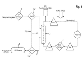
Fig. 1 den Prinzipaufbau bzw. die Strömungsverhältnisse in einer Dialysemaschine gemäß der Erfindung ohne Rezirkulation, -
Fig. 2 den Prinzipaufbau bzw. die Strömungsverhältnisse in einer Dialysemaschine gemäß der Erfindung mit Rezirkulation, -
Fig. 3 den Blutkreislauf im Shuntbereich ohne Rezirkulation bei Bolusgabe, -
Fig. 4 den Blutkreislauf im Shuntbereich mit Rezirkulation bei Bolusgabe und -
Fig. 5 den qualitativen Verlauf eines UV - Sensorsignals bei venöser Bolusgabe am Shunt und Rezirkulation. - Aus der
Fig. 1 ist der prinzipielle Aufbau einer Dialysemaschine (Dialysierflüssigkeitsströmung) ohne eine Rezirkulation gemäß der vorliegenden Erfindung dargestellt. Demnach fördert eine Blutpumpe 1 Blut aus dem Körper eines Patienten über (im Folgenden nicht näher spezifizierte) Druckmesseinrichtungen in einen Dialysator 2, in welchen maschinenseitig sowie in Gegenstromrichtung zum Blut eine Dialysierflüssigkeit mittels einer Dialysierflüssigkeitspumpe 4 gepumpt wird. Blut und Dialysierflüssigkeit sind durch eine semipermeable Membran (nicht näher dargestellt) voneinander getrennt, die für urämische Toxine in Richtung Dialysierflüssigkeit durchlässig ist. Die mit urämischen Toxinen angereicherte Dialysierflüssigkeit wird dann aus dem Dialysator 2 abgeführt. - Zumindest ein UV - Sensor 6 befindet sich in/an einer Abflussleitung 8 stromab zum Dialysator 2 und misst während einer Dialysetherapie die (UV - Licht) Absorbanz im Abfluss (Dialysierflüssigkeit) kontinuierlich. Zu Beginn wird zur Kalibrierung des Systems (Sensorik) ein Detektor 0 - Wert mit reiner Dialyseflüssigkeit (ohne urämische Toxine) ermittelt und zwar vorzugsweise zu einem Zeitpunkt, zu welchem der Patient noch nicht an die Dialysemaschine angelegt ist oder in dem der Dialysator 2 über eine Umgehungsleitung 10 kurzgeschlossen wird, welche an zwei Ventilen 12, 14 mit dem Ein- und Ausgang des Dialysators 2 fluidverbindbar ist. In letzterem Fall (Bypass - Lösung) ist der UV - Sensor 6 stromab zu der Ungehungsleitung 19 am Dialysatorabfluss 8 platziert. Anschließend wird die Dialysierflüssigkeit wieder über den Dialysator 2 geleitet und kontinuierlich oder getaktet vom UV - Sensor gemessen. Die dabei erzeugten Sensorsignale Detektor i werden dann einer nicht weiter dargestellten Recheneinheit zugesandt, welche hieraus den aktuelle (UV - Licht) Absorbanzwert wie Folgt ermittelt:

- Wie bereits vorstehend ausgeführt wurde, ist der Detektor 0 - Wert das zu Beginn der Dialysebehandlung kalibrierte Level, das mit einer Dialysierflüssigkeit ohne die zu messenden Substanzen durchgeführt wird. Der Dialysierflüssigkeitsfluss, der Blutfluss und der verwendete Dialysator 2 beeinflussen die Absorbanz und somit auch die vorherrschende Clearance (Anteil des Blutflusses zum Gesamtblutfluss, der vollständig von urämischen Toxinen gereinigt ist), die maßgeblich für die (UV - Licht) Absorbanz im Abfluss ist. Dabei werden die entzogenen Giftstoffe von der Blutseite durch den Dialysierflüssigkeitsfluss verdünnt und dann im Abfluss durch den zumindest einen UV - Sensor 6 gemessen.
- Wie bereits eingangs beschrieben wurde, wird während einer Rezirkulation im Shunt schon gereinigtes Blut aus dem venösen Zugang wieder in den arteriellen Zugang zurückgesaugt. Die Rezirkulation (in %) ist dabei das Verhältnis zwischen gereinigtem Blut und dem aktuellen Blutfluss. Dadurch wird nicht die tatsächliche im Patienten aktuell vorhandene Konzentration an Giftstoffen zum Dialysator 2 befördert, sondern nur eine Verdünnung mit bereits gereinigtem Blut, wodurch sich die Dialyseeffektivität natürlich verringert.
- In der
Fig. 2 ist die erfindungsgemäße Dialysemaschine in einem Rezirkulationszustand prinzipiell dargestellt. Demnach wird gereinigtes Blut in den venösen Zugang 16 abgeführt und gleich im Anschluss daran parallel zum arteriellen Patientenblut erneut in den arteriellen Zugang 18 eingesaugt. Der inFig. 2 gekennzeichnete Blutfluss parallel zum Patientenkörper bezeichnet hierbei die Rezirkulation. - Sie lässt sich errechnen aus:


- mit QB = Gesamtblutfluss
- QR = Rezirkulationsblutfluss
- QP = Patientenblutfluss
- Ausgehend von den vorstehenden Grundbetrachtungen lässt sich die absolute Rezirkulation auf die nachfolgend beschriebene Weise bestimmen:
- Eine getriggerte Messung zur Bestimmung einer absoluten Rezirkulation in einem Shunt erfolgt erfindungsgemäß durch die Zugabe eines Bolus in den venösen Zugang. Dieses Verfahren kann auch bei einer nicht plötzlich auftretenden Rezirkulation (kontinuierlich) durchgeführt werden und bestimmt/berechnet den Absolutwert der Rezirkulation.
- Die Bolusgabe kann zunächst auf verschiedenen Wegen mittels Spritze, Rückfiltration, Substitutionspumpe, etc. in den venösen extrakorporalen Kreislauf erfolgen und muss nur (unmittelbar) vor dem venösen Zugang zugegeben werden. Der Bolus selbst sollte dabei vorzugsweise aus einer nicht absorbierenden Substanz (z.B. NaCl) bestehen. Sofern die Konzentration des Bolus bekannt ist und diese Konzentration ebenfalls auf den UV- Sensor kalibriert ist, kann alternativ auch mit einer absorbierenden Bolussubstanz gearbeitet werden.
- Grundsätzlich wird eine bestimmte Bolusmenge (Volumen) QBven beispielsweise 10ml an NaCl venös dem Patienten zugegeben. Die Menge des Bolus kann hierfür adaptiv an den Blutfluss angepasst und somit optimal berechnet werden oder durch eine fixierte Menge definiert sein. Vorzugsweise erfolgt die Bolusgabe ferner bei einem gestoppten Blutfluss, wobei aber auch eine Bolusgabe parallel zum fließenden Blutfluss erfolgen kann.
- Die
Fig. 3 und4 zeigen das Systemverhalten mit und ohne Rezirkulation bei einem Bolus gemäß der vorstehenden Definition. InFig. 3 ist jenes Verhalten gezeigt, bei welchem keine Rezirkulation auftritt, wohingegenFig. 4 das Verhalten mit einer Rezirkulation und der verdünnten Flüssigkeit im arteriellen Zugang darstellt. Demzufolge gelangt der Bolus gemäß derFig. 3 über den venösen Zugang ausschließlich in den Patientenkörper und von dort in nicht mehr wahrnehmbarer Konzentration in den arteriellen Zugang. In diesem erfasst der UV - Sensor dann keine Absorbanzwertänderung unmittelbar im Anschluss an eine Bolusgabe. - Anders verhält sich das System gemäß der
Fig. 4 . Dort gelangt der Bolus nicht nur ausschließlich in den Patientenkörper, sondern anteilsmäßig auch unmittelbar in den arteriellen Zugang. Dies führt zu einer raschen Verringerung des dialysierflüssigkeitsseitig gemessenen Absorbanzwerts gegenüber jenem Wert, wie er zeitlich vor der Bolusgabe vorgeherrscht hat, infolge einer Rezirkulation größer null (%). - D.h., sofern keine Rezirkulation im Shunt vorhanden ist, erfolgt vor und nach der Bolusgabe keine Signaländerung bezüglich der Absorbanz bzw. des UV-Sensorsignals, da nur ungereinigtes Blut durch den arteriellen Zugang aufgenommen wird, wohingegen sich der Bolus im Patientenkörper verteilt/verflüchtigt. Eine Rezirkulation im Shunt hingegen (siehe
Fig. 4 ) verursacht eine direkte Signaländerung am UV - Sensor durch eine Verringerung der Konzentration an urämischen Toxinen (Harnsäurekonzentration) im arteriellen Zugang und damit in der Dialysierflüssigkeit. Dabei wird bereits gereinigtes Blut und auch der Bolus aus dem venösen Zugang wieder direkt (ohne über den Patientenkörper zu gehen) durch den arteriellen Zugang aufgenommen und am Dialysator vorbei geführt. Dies führt zu einer geringeren entfernten Menge an urämischen Toxinen und somit auch zu einer geringeren Harnsäurekonzentration (Konzentrationssprung) im Dialysierflüssigkeisabfluss. - Ein qualitativer Signalverlauf am UV - Sensor im Fall einer Bolusgabe bei Rezirkulation ist in der
Fig. 5 dargestellt. Demnach zeigt das Erfassungssignal vor der Bolusgabe einen im Wesentlichen konstanten Verlauf, um dann unmittelbar nach der Bolusgabe einen Signalsprung auszuführen, der eine im Wesentlichen abrupte Konzentrationsänderung an urämischen Toxinen in der Dialysierflüssigkeit anzeigt. Sobald der Bolus den Dialysator passiert hat, kehrt das Sensorsignal allmählich wieder auf seinen Wert vor der Bolusgabe zurück. - Eine Integralbildung über den Signalverlauf für eine bestimmte Zeitspanne vor und nach der Bolusgabe bildet dabei die Grundlage für die quantitative Signalauswertung durch die nicht weiter dargestellte Recheneinheit. Die Messgröße für die Detektion der Rezirkulation mit dem dargestellten UV - Sensor ist demnach (alleinig) das Detektorsignal, das sich aufgrund einer Regelung nur mit der Harnsäurekonzentration und somit mit der proportionalen Absorbanz in der Dialysierflüssigkeit ändert.
- Um den genauen Rezirkulationsgrad zu messen / berechnen muss also die Berechnung durch die Absorbanz erfolgen, da diese direkt proportional zur Konzentration ist. Der zugegebene Bolus erreicht gemäß der
Fig. 4 demnach vermischt/verdünnt den venösen Zugang und dient als Ausgangssubstanz für die Rezirkulationsbestimmung. Mit Hilfe der zwei genannten Integralsflächen A, B gemäß derFig. 5 ist es nun möglich, den Rezirkulationsgrad (quantitativ) zu errechnen/bestimmen. - Die Fläche A spiegelt den stationären Wert wieder, der sich in der Dialysierflüssigkeit ohne Boluseinfluss eingependelt hat. Durch den Bolus wird dieses System verändert und für einen kurzen Zeitraum die Konzentration verändert. Diese Änderung kann nunmehr über die Verhältnisse der Absorbanzen bestimmt werden. Voraussetzung dabei ist jedoch die Kenntnis über das Volumen QBven des Bolus, der in den venösen Zugang gegeben wurde.
- Die Berechnung erfolgt dann durch die Bestimmung der Integralflächen A, B. Die Messlänge der Integralflächen muss hierfür nicht notwendiger Weise gleich lang sein. Bei unterschiedlichen Längen muss jedoch die Bolusmenge durch die Messlänge berechnet werden. Aus der Differenz der beiden Integralsflächen

wird die Differenzfläche C gebildet. Diese ist durch die Zugabe des Bolus entstanden und ist direkt proportional zum Bolus (rezirkulierte Menge). D.h., sofern A = B ist, tritt keine messbare Rezirkulation im System auf. Die Kenntnis der Menge QBven über den zugegebenen Bolus ermöglicht nunmehr die Berechnung der Rezirkulation. Dies ist das Verhältnis aus der Menge des eingegebenen venösen Bolus QBven und des davon arteriell aufgenommenen (rezirkulierten) Teils QBart.
- Die arterielle Bolusmenge QBart ist jene Bolusmenge in ml, die dem Anteil im arteriellen Zugang durch Rezirkulation entspricht. Die Bestimmung erfolgt durch die Berechnung des Verhältnisses der Integralflächen A, B und des effektiven Blutflusses.
- Die Flächen A bis C werden aus dem Detektorsignal berechnet. Die Anpassung erfolgt z.B. durch eine Gaus Funktion 7. Ordnung oder eine andere verwendbare mathematische Funktion zur Flächenbestimmung.

- Die Berechnung eines C - Detektorwerts und eines A - Detektorwerts der jeweiligen Flächen C und A erfolgt ferner durch die Mittelwertbildung der jeweiligen Fläche über den bestimmten Messzeitraum. Dadurch wird die effektive Fläche berechnet und man kann über die Flächen die Änderung des Mischungsverhältnisses (Dialysierflüssigkeit / urämische Toxine) in der Dialysierflüssigkeit durch die Berechnung der Absorbanz bestimmen.
- D.h. die jeweilige Fläche wird in die Absorbanz umgerechnet und ist somit proportional zur Konzentration. Ein punktweiser Vergleich ist ebenfalls möglich, weist aber eine geringere Messgenauigkeit auf. Die Absorbanz allgemein berechnet sich aus: (Detektor0 = 55000 wird beispielhaft als das Ausgangslevel mit reiner Dialysierflüssigkeit angenommen)


- Die gesamte Bestimmung der absoluten Rezirkulation erfolgt dann mit der folgenden Berechnungsformel:

- Zusammenfassend wird ein Verfahren und eine dieses implementierende Vorrichtung zur dialysierflüssigkeitsseitigen Erfassung einer Rezirkulation durch blutseitige Bolusgabe offenbart mit den folgenden Verfahrensschritten:
- Spektralphotometrisches Messen eines ersten Licht - Absorbanzwerts (ad) einer von einem Dialysator abfließenden Dialysierflüssigkeit (d) vor Bolusgabe,
- Venöse Bolusgabe mit vorbekanntem Volumen (QBven) am venösen Zugang, Spektralphotometrisches Messen eines zweiten Licht - Absorbanzwerts (bd) der abfließenden Dialysierflüssigkeit nach Bolusgabe und
- Ermitteln einer Absorbanzwertänderung (Absorbanzdifferenz) zwischen dem ersten (ad) und zweiten gemessenen Absorbanzwerten (bd) infolge einer Bolus - Präsenz in der Dialysierflüssigkeit bei Rezirkulation als Grundlage für eine optionale Rezirkulationsquantifizierung.
Claims (6)
- Verfahren zur dialysierflüssigkeitsseitigen Erfassung einer Rezirkulation durch blutseitige Bolusgabe mit den folgenden Verfahrensschritten:Spektralphotometrisches Messen eines ersten Licht - Absorbanzwerts (ad) einer von einem Dialysator abfließenden Dialysierflüssigkeit (d) vor Bolusgabe,Venöse Bolusgabe mit vorbekanntem Volumen (QBven) am venösen Zugang,Spektralphotometrisches Messen eines zweiten Licht - Absorbanzwerts (bd) der abfließenden Dialysierflüssigkeit nach Bolusgabe undErmitteln einer Absorbanzswertänderung zwischen dem ersten (ad) und zweiten gemessenen Absorbanzwerten (bd) infolge einer Bolus - Präsenz in der Dialysierflüssigkeit bei Rezirkulation als Grundlage für die Rezirkulationsquantifizierung.
- Verfahren nach Anspruch 1, gekennzeichnet durch die weiteren Verfahrensschritte:Integralbildung über den Absorbanz - Änderungsverlauf für die ersten und zweiten Absorbanzwerte (ad, bd) vor und nach dem Bolus,Differenzbildung zwischen den beiden Integralwerten (A, B) vor und nach dem Bolus undIdentifizieren eines Rezirkulationszustands bei einer Differenz (C) ungleich null.
- Verfahren nach Anspruch 2, gekennzeichnet durch die weiteren Verfahrensschritte:Umrechnen des Integralwerts (A) sowie der Integralwertdifferenz (C) in zugehörige Absorbanzwerte (AA, CA),Berechnen der arteriellen Bolusmenge (Qart) aus dem Verhältnis der Absorbanzwerte (AA, CA) undBerechnen des Rezirkulationsgrads aus dem Verhältnis der errechneten arteriellen Bolusmenge (QBart) zu der vorbekannten venösen Bolusmenge (QBven).
- Verfahren nach einem der vorstehenden Ansprüche, dadurch gekennzeichnet, dass der Bolus keine Absorbanzeigenschaften bezüglich des in die Dialysierflüssigkeit emittierten Lichts hat.
- Verfahren nach einem der Ansprüche 1 bis 3, dadurch gekennzeichnet, dass der Bolus vorbekannte Absorbanzeigenschaften bezüglich des in die Dialysierflüssigkeit emittierten Lichts vorzugsweise im Bereich der urämischen Toxine in der Dialysierflüssigkeit hat.
- Dialysemaschine mit einer Vorrichtung zur dialysierflüssigkeitsseitigen Erfassung einer Rezirkulation durch blutseitige Bolusgabe unter Implementierung des Verfahrens gemäß einem der Ansprüche 1 bis 5 mit einer Lichtquelle, die Licht mit einer Wellenlänge von 250 - 300nm und vorzugsweise 280nm emittiert, mindestens einem UV-Sensor unmittelbar am Abfluss eines Dialysators und einer Recheneinheit, welche Sensorsignale bezüglich der UV - Absorbanz der Dialysierflüssigkeit vor und nach einer blutseitig venösen Bolusgabe erhält.
Applications Claiming Priority (1)
| Application Number | Priority Date | Filing Date | Title |
|---|---|---|---|
| DE102013103222.2A DE102013103222A1 (de) | 2013-03-28 | 2013-03-28 | Rezirkulationsdetektion durch Bolusgabe |
Publications (2)
| Publication Number | Publication Date |
|---|---|
| EP2783713A1 true EP2783713A1 (de) | 2014-10-01 |
| EP2783713B1 EP2783713B1 (de) | 2020-08-05 |
Family
ID=50230991
Family Applications (1)
| Application Number | Title | Priority Date | Filing Date |
|---|---|---|---|
| EP14157989.6A Active EP2783713B1 (de) | 2013-03-28 | 2014-03-06 | Rezirkulationsdetektion durch Bolusgabe |
Country Status (4)
| Country | Link |
|---|---|
| US (1) | US9370614B2 (de) |
| EP (1) | EP2783713B1 (de) |
| CN (2) | CN104069559B (de) |
| DE (1) | DE102013103222A1 (de) |
Cited By (2)
| Publication number | Priority date | Publication date | Assignee | Title |
|---|---|---|---|---|
| CN106896082A (zh) * | 2017-04-26 | 2017-06-27 | 上海健康医学院 | 一种血透血液中尿素氮肌酐含量在线监测方法及系统 |
| EP4681747A1 (de) | 2024-07-16 | 2026-01-21 | B. Braun Avitum AG | Extrakorporale blutbehandlungsmaschine, computerimplementiertes detektionsverfahren, sowie computerprogramm |
Families Citing this family (7)
| Publication number | Priority date | Publication date | Assignee | Title |
|---|---|---|---|---|
| DE102013104501A1 (de) * | 2013-05-02 | 2014-11-06 | B. Braun Avitum Ag | Vorrichtung zur extrakorporalen Blutbehandlung |
| DE102016119259A1 (de) | 2016-10-10 | 2018-04-12 | B. Braun Avitum Ag | Vorrichtung und Verfahren zur Rezirkulationsmessung |
| DE102019110218A1 (de) * | 2019-04-17 | 2020-10-22 | B.Braun Avitum Ag | Rezirkulationsmessung mittels Diffusionsgleichgewicht |
| EP3991764B1 (de) | 2020-10-27 | 2024-03-06 | Bellco S.r.l. | Durchflussmesser zum dosieren von wasser in einem dialysesystem |
| US12318528B2 (en) | 2020-10-30 | 2025-06-03 | Mozarc Medical Us Llc | Variable orifice fistula graft |
| EP3991770B1 (de) | 2020-10-30 | 2024-10-30 | Bellco S.r.l. | Dialysekassette mit pumpfunktionen |
| EP4008376A1 (de) | 2020-12-03 | 2022-06-08 | Medtronic, Inc. | Flexibles rohr-routing-zubehör für peritoneal dialysis system |
Citations (7)
| Publication number | Priority date | Publication date | Assignee | Title |
|---|---|---|---|---|
| US5685989A (en) | 1994-09-16 | 1997-11-11 | Transonic Systems, Inc. | Method and apparatus to measure blood flow and recirculation in hemodialysis shunts |
| EP0900094A1 (de) | 1997-01-24 | 1999-03-10 | Fresenius Medical Care Deutschland GmbH | Verfahren zur bestimmung der rezirkulation während einer extrakorporalen blutbehandlung und vorrichtung zur durchführung des verfahrens |
| DE69916053T2 (de) | 1998-06-04 | 2005-03-03 | Althin Medical Ab | Verfahren und bestimmung von abfallprodukten in dialyseflüssigkeiten während dialysebehandlungen |
| US20060096348A1 (en) * | 2004-11-10 | 2006-05-11 | Difiore Attilio E | Method for measuring recirculation in catheters |
| US7815852B2 (en) | 2003-11-20 | 2010-10-19 | Gambro Lundia Ab | Method, apparatus and software program for measurement of a parameter relating to a heart-lung system of a mammal |
| EP2292283A1 (de) * | 2009-09-04 | 2011-03-09 | B. Braun Avitum AG | Vorrichtung und Verfahren zum Erhalt physiologischer Parameter und zur Erkennung klinischer oder subklinischen Anomalien während einer Nierenersatzbehandlung |
| DE102011008482A1 (de) * | 2010-03-09 | 2012-01-19 | Ldiamon As | UV-Detektoranordnung |
Family Cites Families (9)
| Publication number | Priority date | Publication date | Assignee | Title |
|---|---|---|---|---|
| DE19747360B8 (de) * | 1997-10-27 | 2007-05-16 | Fresenius Medical Care De Gmbh | Verfahren zur Messung von Leistungsparametern von Stoff- und Energieaustausch Modulen |
| US6702774B1 (en) * | 1997-10-27 | 2004-03-09 | Fresenius Medical Care Deutschland Gmbh | Method of measuring dialysis or clearance of hemodialysis systems |
| US6648845B1 (en) * | 1998-01-07 | 2003-11-18 | Fresenius Medical Care North America | Method and apparatus for determining hemodialysis parameters |
| CA2514239C (en) * | 2003-01-28 | 2012-03-20 | Gambro Lundia Ab | An apparatus and method for monitoring a vascular access of a patient |
| CN100548392C (zh) * | 2004-08-24 | 2009-10-14 | 日机装株式会社 | 血液净化装置 |
| JP4925159B2 (ja) * | 2005-10-12 | 2012-04-25 | 日機装株式会社 | 血液浄化装置 |
| US20080149563A1 (en) * | 2006-12-22 | 2008-06-26 | Renal Solutions, Inc. | Method of controlling dialysis using blood circulation times |
| DE102007056475A1 (de) | 2007-11-22 | 2009-06-04 | Fresenius Medical Care Deutschland Gmbh | Verfahren und Vorrichtung zum Bestimmen der Rezirkulation in einer Fistel oder der kardiopulmonalen Rezirkulation sowie Blutbehandlungsvorrichtung mit einer Vorrichtung zur Bestimmung der Fistelrezirkulation oder des kardiopulmonalen Rezirkulationsanteils |
| DE102011102962A1 (de) * | 2011-05-23 | 2012-11-29 | Fresenius Medical Care Deutschland Gmbh | Vorrichtung und Verfahren zur Erkennung eines Betriebszustandes einer extrakorporalen Blutbehandlung |
-
2013
- 2013-03-28 DE DE102013103222.2A patent/DE102013103222A1/de active Pending
-
2014
- 2014-03-06 EP EP14157989.6A patent/EP2783713B1/de active Active
- 2014-03-18 US US14/217,991 patent/US9370614B2/en active Active
- 2014-03-27 CN CN201410119663.5A patent/CN104069559B/zh active Active
- 2014-03-27 CN CN201420144005.7U patent/CN204411383U/zh not_active Expired - Lifetime
Patent Citations (7)
| Publication number | Priority date | Publication date | Assignee | Title |
|---|---|---|---|---|
| US5685989A (en) | 1994-09-16 | 1997-11-11 | Transonic Systems, Inc. | Method and apparatus to measure blood flow and recirculation in hemodialysis shunts |
| EP0900094A1 (de) | 1997-01-24 | 1999-03-10 | Fresenius Medical Care Deutschland GmbH | Verfahren zur bestimmung der rezirkulation während einer extrakorporalen blutbehandlung und vorrichtung zur durchführung des verfahrens |
| DE69916053T2 (de) | 1998-06-04 | 2005-03-03 | Althin Medical Ab | Verfahren und bestimmung von abfallprodukten in dialyseflüssigkeiten während dialysebehandlungen |
| US7815852B2 (en) | 2003-11-20 | 2010-10-19 | Gambro Lundia Ab | Method, apparatus and software program for measurement of a parameter relating to a heart-lung system of a mammal |
| US20060096348A1 (en) * | 2004-11-10 | 2006-05-11 | Difiore Attilio E | Method for measuring recirculation in catheters |
| EP2292283A1 (de) * | 2009-09-04 | 2011-03-09 | B. Braun Avitum AG | Vorrichtung und Verfahren zum Erhalt physiologischer Parameter und zur Erkennung klinischer oder subklinischen Anomalien während einer Nierenersatzbehandlung |
| DE102011008482A1 (de) * | 2010-03-09 | 2012-01-19 | Ldiamon As | UV-Detektoranordnung |
Cited By (3)
| Publication number | Priority date | Publication date | Assignee | Title |
|---|---|---|---|---|
| CN106896082A (zh) * | 2017-04-26 | 2017-06-27 | 上海健康医学院 | 一种血透血液中尿素氮肌酐含量在线监测方法及系统 |
| CN106896082B (zh) * | 2017-04-26 | 2024-02-13 | 上海健康医学院 | 一种血透血液中尿素氮肌酐含量在线监测方法及系统 |
| EP4681747A1 (de) | 2024-07-16 | 2026-01-21 | B. Braun Avitum AG | Extrakorporale blutbehandlungsmaschine, computerimplementiertes detektionsverfahren, sowie computerprogramm |
Also Published As
| Publication number | Publication date |
|---|---|
| EP2783713B1 (de) | 2020-08-05 |
| CN104069559A (zh) | 2014-10-01 |
| DE102013103222A1 (de) | 2014-10-02 |
| US20140291534A1 (en) | 2014-10-02 |
| US9370614B2 (en) | 2016-06-21 |
| CN104069559B (zh) | 2017-08-25 |
| CN204411383U (zh) | 2015-06-24 |
Similar Documents
| Publication | Publication Date | Title |
|---|---|---|
| EP2783713B1 (de) | Rezirkulationsdetektion durch Bolusgabe | |
| EP2897669B1 (de) | Vorrichtung zur erkennung der rezirkulation während einer extrakorporalen blutbehandlung | |
| EP2714128B1 (de) | Vorrichtung und verfahren zur erkennung eines betriebszustandes einer extrakorporalen blutbehandlung | |
| EP2203198B1 (de) | Verfahren und vorrichtung zur überwachung der zufuhr von substitutionsflüssigkeit während einer extrakorporalen blutbehandlung | |
| EP2985045B1 (de) | Verfahren zum einstellen eines blutflusses in einer dialysevorrichtung und dialysevorrichtung | |
| EP1197236B1 (de) | Verfahren zur Bestimmung des Intraperitonealvolumens und Vorrichtung zur Peritonealdialyse | |
| EP2783715B1 (de) | Verfahren zur Erfassung einer Rezirkulation in einem arteriovenösen Shunt während laufender Hämodialyse und Dialysesystem | |
| EP3034110B1 (de) | Verfahren und vorrichtung zur bestimmung des transmembrandrucks bei einer extrakorporalen blutbehandlung | |
| EP2799097B1 (de) | Vorrichtung zur extrakorporalen Blutbehandlung | |
| EP2249898B1 (de) | Verfahren zum bestimmen des anteils der rezirkulation in einer fistel und/oder der kardiopulmonalen rezirkulation an der summe von fistelrezirkulation und kardiopulmonaler rezirkulation | |
| EP3431118B1 (de) | Vorrichtung zur durchführung einer isonaträmischen dialyse | |
| DE102014011699B4 (de) | Vorrichtung zur Ermittlung eines optimalen Dialysatflusses für eine extrakorporale Blutbehandlung mit einer extrakorporalen Blutbehandlungsvorrichtung | |
| DE102010052070A1 (de) | Verfahren und Vorrichtung zur Anpassung des Substitutionsziels bei der Ultrafiltration von Blut | |
| WO2004033001A1 (de) | Verfahren zur blutrückgabe aus einer blutbehandlungsvorrichtung und vorrichtung zur durchführung des verfahrens | |
| EP2722064A1 (de) | Dialyseoptimierungsverfahren | |
| EP2432518B1 (de) | Vorrichtung und verfahren zur erkennung eines schlauchleitungssystems für eine extrakorporale blutbehandlungsvorrichtung | |
| WO2013079169A1 (de) | Verfahren und vorrichtung zur bestimmung eines blutbestandteils | |
| WO2020212332A1 (de) | Rezirkulationsmessung mittels diffusionsgleichgewicht | |
| EP2696911B1 (de) | Verfahren und vorrichtung zur anpassung der mittelmolekularen reinigungsleistung durch einstellung des substitutionsflusses | |
| EP2783714B1 (de) | Verfahren und Vorrichtung zur Bestimmung eines Rezirkulationszustands | |
| EP2783716B1 (de) | Verfahren und Vorrichtung zur Erkennung einer Rezirkulation in einem Shunt | |
| EP2461845B1 (de) | Vorrichtung zur extrakorporalen blutbehandlung | |
| EP4142822B1 (de) | Dialysevorrichtung mit einer vorrichtung zur bestimmung von mindestens zwei hämodialyseparametern | |
| DE102024206668A1 (de) | Extrakorporale blutbehandlungsmaschine, computerimplementiertes detektionsverfahren, sowie computerprogramm |
Legal Events
| Date | Code | Title | Description |
|---|---|---|---|
| 17P | Request for examination filed |
Effective date: 20140306 |
|
| AK | Designated contracting states |
Kind code of ref document: A1 Designated state(s): AL AT BE BG CH CY CZ DE DK EE ES FI FR GB GR HR HU IE IS IT LI LT LU LV MC MK MT NL NO PL PT RO RS SE SI SK SM TR |
|
| AX | Request for extension of the european patent |
Extension state: BA ME |
|
| PUAI | Public reference made under article 153(3) epc to a published international application that has entered the european phase |
Free format text: ORIGINAL CODE: 0009012 |
|
| R17P | Request for examination filed (corrected) |
Effective date: 20141105 |
|
| RBV | Designated contracting states (corrected) |
Designated state(s): AL AT BE BG CH CY CZ DE DK EE ES FI FR GB GR HR HU IE IS IT LI LT LU LV MC MK MT NL NO PL PT RO RS SE SI SK SM TR |
|
| STAA | Information on the status of an ep patent application or granted ep patent |
Free format text: STATUS: EXAMINATION IS IN PROGRESS |
|
| 17Q | First examination report despatched |
Effective date: 20170920 |
|
| GRAP | Despatch of communication of intention to grant a patent |
Free format text: ORIGINAL CODE: EPIDOSNIGR1 |
|
| STAA | Information on the status of an ep patent application or granted ep patent |
Free format text: STATUS: GRANT OF PATENT IS INTENDED |
|
| INTG | Intention to grant announced |
Effective date: 20200224 |
|
| GRAS | Grant fee paid |
Free format text: ORIGINAL CODE: EPIDOSNIGR3 |
|
| GRAA | (expected) grant |
Free format text: ORIGINAL CODE: 0009210 |
|
| STAA | Information on the status of an ep patent application or granted ep patent |
Free format text: STATUS: THE PATENT HAS BEEN GRANTED |
|
| AK | Designated contracting states |
Kind code of ref document: B1 Designated state(s): AL AT BE BG CH CY CZ DE DK EE ES FI FR GB GR HR HU IE IS IT LI LT LU LV MC MK MT NL NO PL PT RO RS SE SI SK SM TR |
|
| REG | Reference to a national code |
Ref country code: GB Ref legal event code: FG4D Free format text: NOT ENGLISH |
|
| REG | Reference to a national code |
Ref country code: CH Ref legal event code: EP |
|
| REG | Reference to a national code |
Ref country code: AT Ref legal event code: REF Ref document number: 1297820 Country of ref document: AT Kind code of ref document: T Effective date: 20200815 |
|
| REG | Reference to a national code |
Ref country code: DE Ref legal event code: R096 Ref document number: 502014014548 Country of ref document: DE |
|
| REG | Reference to a national code |
Ref country code: IE Ref legal event code: FG4D Free format text: LANGUAGE OF EP DOCUMENT: GERMAN |
|
| REG | Reference to a national code |
Ref country code: SE Ref legal event code: TRGR |
|
| REG | Reference to a national code |
Ref country code: LT Ref legal event code: MG4D |
|
| REG | Reference to a national code |
Ref country code: NL Ref legal event code: MP Effective date: 20200805 |
|
| PG25 | Lapsed in a contracting state [announced via postgrant information from national office to epo] |
Ref country code: FI Free format text: LAPSE BECAUSE OF FAILURE TO SUBMIT A TRANSLATION OF THE DESCRIPTION OR TO PAY THE FEE WITHIN THE PRESCRIBED TIME-LIMIT Effective date: 20200805 Ref country code: GR Free format text: LAPSE BECAUSE OF FAILURE TO SUBMIT A TRANSLATION OF THE DESCRIPTION OR TO PAY THE FEE WITHIN THE PRESCRIBED TIME-LIMIT Effective date: 20201106 Ref country code: HR Free format text: LAPSE BECAUSE OF FAILURE TO SUBMIT A TRANSLATION OF THE DESCRIPTION OR TO PAY THE FEE WITHIN THE PRESCRIBED TIME-LIMIT Effective date: 20200805 Ref country code: NO Free format text: LAPSE BECAUSE OF FAILURE TO SUBMIT A TRANSLATION OF THE DESCRIPTION OR TO PAY THE FEE WITHIN THE PRESCRIBED TIME-LIMIT Effective date: 20201105 Ref country code: PT Free format text: LAPSE BECAUSE OF FAILURE TO SUBMIT A TRANSLATION OF THE DESCRIPTION OR TO PAY THE FEE WITHIN THE PRESCRIBED TIME-LIMIT Effective date: 20201207 Ref country code: ES Free format text: LAPSE BECAUSE OF FAILURE TO SUBMIT A TRANSLATION OF THE DESCRIPTION OR TO PAY THE FEE WITHIN THE PRESCRIBED TIME-LIMIT Effective date: 20200805 Ref country code: LT Free format text: LAPSE BECAUSE OF FAILURE TO SUBMIT A TRANSLATION OF THE DESCRIPTION OR TO PAY THE FEE WITHIN THE PRESCRIBED TIME-LIMIT Effective date: 20200805 Ref country code: BG Free format text: LAPSE BECAUSE OF FAILURE TO SUBMIT A TRANSLATION OF THE DESCRIPTION OR TO PAY THE FEE WITHIN THE PRESCRIBED TIME-LIMIT Effective date: 20201105 |
|
| PG25 | Lapsed in a contracting state [announced via postgrant information from national office to epo] |
Ref country code: PL Free format text: LAPSE BECAUSE OF FAILURE TO SUBMIT A TRANSLATION OF THE DESCRIPTION OR TO PAY THE FEE WITHIN THE PRESCRIBED TIME-LIMIT Effective date: 20200805 Ref country code: NL Free format text: LAPSE BECAUSE OF FAILURE TO SUBMIT A TRANSLATION OF THE DESCRIPTION OR TO PAY THE FEE WITHIN THE PRESCRIBED TIME-LIMIT Effective date: 20200805 Ref country code: LV Free format text: LAPSE BECAUSE OF FAILURE TO SUBMIT A TRANSLATION OF THE DESCRIPTION OR TO PAY THE FEE WITHIN THE PRESCRIBED TIME-LIMIT Effective date: 20200805 Ref country code: RS Free format text: LAPSE BECAUSE OF FAILURE TO SUBMIT A TRANSLATION OF THE DESCRIPTION OR TO PAY THE FEE WITHIN THE PRESCRIBED TIME-LIMIT Effective date: 20200805 Ref country code: IS Free format text: LAPSE BECAUSE OF FAILURE TO SUBMIT A TRANSLATION OF THE DESCRIPTION OR TO PAY THE FEE WITHIN THE PRESCRIBED TIME-LIMIT Effective date: 20201205 |
|
| PG25 | Lapsed in a contracting state [announced via postgrant information from national office to epo] |
Ref country code: CZ Free format text: LAPSE BECAUSE OF FAILURE TO SUBMIT A TRANSLATION OF THE DESCRIPTION OR TO PAY THE FEE WITHIN THE PRESCRIBED TIME-LIMIT Effective date: 20200805 Ref country code: DK Free format text: LAPSE BECAUSE OF FAILURE TO SUBMIT A TRANSLATION OF THE DESCRIPTION OR TO PAY THE FEE WITHIN THE PRESCRIBED TIME-LIMIT Effective date: 20200805 Ref country code: EE Free format text: LAPSE BECAUSE OF FAILURE TO SUBMIT A TRANSLATION OF THE DESCRIPTION OR TO PAY THE FEE WITHIN THE PRESCRIBED TIME-LIMIT Effective date: 20200805 Ref country code: RO Free format text: LAPSE BECAUSE OF FAILURE TO SUBMIT A TRANSLATION OF THE DESCRIPTION OR TO PAY THE FEE WITHIN THE PRESCRIBED TIME-LIMIT Effective date: 20200805 Ref country code: SM Free format text: LAPSE BECAUSE OF FAILURE TO SUBMIT A TRANSLATION OF THE DESCRIPTION OR TO PAY THE FEE WITHIN THE PRESCRIBED TIME-LIMIT Effective date: 20200805 |
|
| REG | Reference to a national code |
Ref country code: DE Ref legal event code: R097 Ref document number: 502014014548 Country of ref document: DE |
|
| PG25 | Lapsed in a contracting state [announced via postgrant information from national office to epo] |
Ref country code: AL Free format text: LAPSE BECAUSE OF FAILURE TO SUBMIT A TRANSLATION OF THE DESCRIPTION OR TO PAY THE FEE WITHIN THE PRESCRIBED TIME-LIMIT Effective date: 20200805 |
|
| PLBE | No opposition filed within time limit |
Free format text: ORIGINAL CODE: 0009261 |
|
| STAA | Information on the status of an ep patent application or granted ep patent |
Free format text: STATUS: NO OPPOSITION FILED WITHIN TIME LIMIT |
|
| PG25 | Lapsed in a contracting state [announced via postgrant information from national office to epo] |
Ref country code: SK Free format text: LAPSE BECAUSE OF FAILURE TO SUBMIT A TRANSLATION OF THE DESCRIPTION OR TO PAY THE FEE WITHIN THE PRESCRIBED TIME-LIMIT Effective date: 20200805 |
|
| 26N | No opposition filed |
Effective date: 20210507 |
|
| PG25 | Lapsed in a contracting state [announced via postgrant information from national office to epo] |
Ref country code: SI Free format text: LAPSE BECAUSE OF FAILURE TO SUBMIT A TRANSLATION OF THE DESCRIPTION OR TO PAY THE FEE WITHIN THE PRESCRIBED TIME-LIMIT Effective date: 20200805 |
|
| PG25 | Lapsed in a contracting state [announced via postgrant information from national office to epo] |
Ref country code: MC Free format text: LAPSE BECAUSE OF FAILURE TO SUBMIT A TRANSLATION OF THE DESCRIPTION OR TO PAY THE FEE WITHIN THE PRESCRIBED TIME-LIMIT Effective date: 20200805 |
|
| REG | Reference to a national code |
Ref country code: CH Ref legal event code: PL |
|
| GBPC | Gb: european patent ceased through non-payment of renewal fee |
Effective date: 20210306 |
|
| REG | Reference to a national code |
Ref country code: BE Ref legal event code: MM Effective date: 20210331 |
|
| PG25 | Lapsed in a contracting state [announced via postgrant information from national office to epo] |
Ref country code: IE Free format text: LAPSE BECAUSE OF NON-PAYMENT OF DUE FEES Effective date: 20210306 Ref country code: GB Free format text: LAPSE BECAUSE OF NON-PAYMENT OF DUE FEES Effective date: 20210306 Ref country code: FR Free format text: LAPSE BECAUSE OF NON-PAYMENT OF DUE FEES Effective date: 20210331 Ref country code: CH Free format text: LAPSE BECAUSE OF NON-PAYMENT OF DUE FEES Effective date: 20210331 Ref country code: LU Free format text: LAPSE BECAUSE OF NON-PAYMENT OF DUE FEES Effective date: 20210306 Ref country code: LI Free format text: LAPSE BECAUSE OF NON-PAYMENT OF DUE FEES Effective date: 20210331 |
|
| REG | Reference to a national code |
Ref country code: AT Ref legal event code: MM01 Ref document number: 1297820 Country of ref document: AT Kind code of ref document: T Effective date: 20210306 |
|
| PG25 | Lapsed in a contracting state [announced via postgrant information from national office to epo] |
Ref country code: BE Free format text: LAPSE BECAUSE OF NON-PAYMENT OF DUE FEES Effective date: 20210331 |
|
| PG25 | Lapsed in a contracting state [announced via postgrant information from national office to epo] |
Ref country code: AT Free format text: LAPSE BECAUSE OF NON-PAYMENT OF DUE FEES Effective date: 20210306 |
|
| PG25 | Lapsed in a contracting state [announced via postgrant information from national office to epo] |
Ref country code: HU Free format text: LAPSE BECAUSE OF FAILURE TO SUBMIT A TRANSLATION OF THE DESCRIPTION OR TO PAY THE FEE WITHIN THE PRESCRIBED TIME-LIMIT; INVALID AB INITIO Effective date: 20140306 |
|
| PG25 | Lapsed in a contracting state [announced via postgrant information from national office to epo] |
Ref country code: CY Free format text: LAPSE BECAUSE OF FAILURE TO SUBMIT A TRANSLATION OF THE DESCRIPTION OR TO PAY THE FEE WITHIN THE PRESCRIBED TIME-LIMIT Effective date: 20200805 |
|
| P01 | Opt-out of the competence of the unified patent court (upc) registered |
Effective date: 20231010 |
|
| PG25 | Lapsed in a contracting state [announced via postgrant information from national office to epo] |
Ref country code: MK Free format text: LAPSE BECAUSE OF FAILURE TO SUBMIT A TRANSLATION OF THE DESCRIPTION OR TO PAY THE FEE WITHIN THE PRESCRIBED TIME-LIMIT Effective date: 20200805 |
|
| PG25 | Lapsed in a contracting state [announced via postgrant information from national office to epo] |
Ref country code: MT Free format text: LAPSE BECAUSE OF FAILURE TO SUBMIT A TRANSLATION OF THE DESCRIPTION OR TO PAY THE FEE WITHIN THE PRESCRIBED TIME-LIMIT Effective date: 20200805 |
|
| PGFP | Annual fee paid to national office [announced via postgrant information from national office to epo] |
Ref country code: IT Payment date: 20250331 Year of fee payment: 12 |
|
| PG25 | Lapsed in a contracting state [announced via postgrant information from national office to epo] |
Ref country code: TR Free format text: LAPSE BECAUSE OF FAILURE TO SUBMIT A TRANSLATION OF THE DESCRIPTION OR TO PAY THE FEE WITHIN THE PRESCRIBED TIME-LIMIT Effective date: 20200805 |
|
| PGFP | Annual fee paid to national office [announced via postgrant information from national office to epo] |
Ref country code: SE Payment date: 20260323 Year of fee payment: 13 |
|
| PGFP | Annual fee paid to national office [announced via postgrant information from national office to epo] |
Ref country code: DE Payment date: 20260320 Year of fee payment: 13 |