EP2783597A1 - Kombinationsregal - Google Patents
Kombinationsregal Download PDFInfo
- Publication number
- EP2783597A1 EP2783597A1 EP20140161673 EP14161673A EP2783597A1 EP 2783597 A1 EP2783597 A1 EP 2783597A1 EP 20140161673 EP20140161673 EP 20140161673 EP 14161673 A EP14161673 A EP 14161673A EP 2783597 A1 EP2783597 A1 EP 2783597A1
- Authority
- EP
- European Patent Office
- Prior art keywords
- component
- combining
- combining portion
- support structure
- combined rack
- Prior art date
- Legal status (The legal status is an assumption and is not a legal conclusion. Google has not performed a legal analysis and makes no representation as to the accuracy of the status listed.)
- Withdrawn
Links
Images


Classifications
-
- A—HUMAN NECESSITIES
- A47—FURNITURE; DOMESTIC ARTICLES OR APPLIANCES; COFFEE MILLS; SPICE MILLS; SUCTION CLEANERS IN GENERAL
- A47B—TABLES; DESKS; OFFICE FURNITURE; CABINETS; DRAWERS; GENERAL DETAILS OF FURNITURE
- A47B88/00—Drawers for tables, cabinets or like furniture; Guides for drawers
- A47B88/90—Constructional details of drawers
- A47B88/941—Drawers being constructed from two or more parts
-
- A—HUMAN NECESSITIES
- A47—FURNITURE; DOMESTIC ARTICLES OR APPLIANCES; COFFEE MILLS; SPICE MILLS; SUCTION CLEANERS IN GENERAL
- A47B—TABLES; DESKS; OFFICE FURNITURE; CABINETS; DRAWERS; GENERAL DETAILS OF FURNITURE
- A47B96/00—Details of cabinets, racks or shelf units not covered by a single one of groups A47B43/00 - A47B95/00; General details of furniture
- A47B96/02—Shelves
- A47B96/025—Shelves with moving elements, e.g. movable extensions or link elements
-
- A—HUMAN NECESSITIES
- A47—FURNITURE; DOMESTIC ARTICLES OR APPLIANCES; COFFEE MILLS; SPICE MILLS; SUCTION CLEANERS IN GENERAL
- A47F—SPECIAL FURNITURE, FITTINGS, OR ACCESSORIES FOR SHOPS, STOREHOUSES, BARS, RESTAURANTS OR THE LIKE; PAYING COUNTERS
- A47F3/00—Show cases or show cabinets
- A47F3/14—Display trays or containers
- A47F3/147—Display trays or containers made of tubes or wire
-
- A—HUMAN NECESSITIES
- A47—FURNITURE; DOMESTIC ARTICLES OR APPLIANCES; COFFEE MILLS; SPICE MILLS; SUCTION CLEANERS IN GENERAL
- A47F—SPECIAL FURNITURE, FITTINGS, OR ACCESSORIES FOR SHOPS, STOREHOUSES, BARS, RESTAURANTS OR THE LIKE; PAYING COUNTERS
- A47F5/00—Show stands, hangers, or shelves characterised by their constructional features
- A47F5/0018—Display racks with shelves or receptables
- A47F5/0025—Display racks with shelves or receptables having separate display containers or trays on shelves or on racks
- A47F5/0031—Display racks with shelves or receptables having separate display containers or trays on shelves or on racks made of tubes or wire
-
- A—HUMAN NECESSITIES
- A47—FURNITURE; DOMESTIC ARTICLES OR APPLIANCES; COFFEE MILLS; SPICE MILLS; SUCTION CLEANERS IN GENERAL
- A47F—SPECIAL FURNITURE, FITTINGS, OR ACCESSORIES FOR SHOPS, STOREHOUSES, BARS, RESTAURANTS OR THE LIKE; PAYING COUNTERS
- A47F5/00—Show stands, hangers, or shelves characterised by their constructional features
- A47F5/0081—Show stands or display racks with movable parts
- A47F5/0093—Show stands or display racks with movable parts movable in a substantially horizontal direction
-
- A—HUMAN NECESSITIES
- A47—FURNITURE; DOMESTIC ARTICLES OR APPLIANCES; COFFEE MILLS; SPICE MILLS; SUCTION CLEANERS IN GENERAL
- A47B—TABLES; DESKS; OFFICE FURNITURE; CABINETS; DRAWERS; GENERAL DETAILS OF FURNITURE
- A47B31/00—Service or tea tables, trolleys, or wagons
- A47B2031/003—Service or tea tables, trolleys, or wagons with drawers, trays or shelves
-
- A—HUMAN NECESSITIES
- A47—FURNITURE; DOMESTIC ARTICLES OR APPLIANCES; COFFEE MILLS; SPICE MILLS; SUCTION CLEANERS IN GENERAL
- A47B—TABLES; DESKS; OFFICE FURNITURE; CABINETS; DRAWERS; GENERAL DETAILS OF FURNITURE
- A47B88/00—Drawers for tables, cabinets or like furniture; Guides for drawers
- A47B88/40—Sliding drawers; Slides or guides therefor
- A47B88/42—Vertically-oriented drawers, i.e. drawers where the height exceeds the width
- A47B2088/421—Vertically-oriented drawers, i.e. drawers where the height exceeds the width the bottom, cabinet side slide having a U-shape section opening upwards
-
- A—HUMAN NECESSITIES
- A47—FURNITURE; DOMESTIC ARTICLES OR APPLIANCES; COFFEE MILLS; SPICE MILLS; SUCTION CLEANERS IN GENERAL
- A47B—TABLES; DESKS; OFFICE FURNITURE; CABINETS; DRAWERS; GENERAL DETAILS OF FURNITURE
- A47B88/00—Drawers for tables, cabinets or like furniture; Guides for drawers
- A47B88/90—Constructional details of drawers
- A47B2088/902—Corner connectors for drawers
-
- A—HUMAN NECESSITIES
- A47—FURNITURE; DOMESTIC ARTICLES OR APPLIANCES; COFFEE MILLS; SPICE MILLS; SUCTION CLEANERS IN GENERAL
- A47B—TABLES; DESKS; OFFICE FURNITURE; CABINETS; DRAWERS; GENERAL DETAILS OF FURNITURE
- A47B2210/00—General construction of drawers, guides and guide devices
- A47B2210/04—Metal wire drawers
Definitions
- the disclosure relates to a rack, more particularly to a combined rack with adjustable widths.
- the left and right sides of a combined rack are usually equipped with a sliding rail respectively to enable itself to be pulled out from the cabinet or be pushed into the cabinet.
- the combined rack comprises at least two sliding-sleeve members, multiple side components (on the front side as well as the back side) and a carrying member.
- the sliding-sleeve members are sleeved on the two sliding rails respectively.
- the sliding rail is disposed on the cabinet and the sliding-sleeve member usually has a connecting portion corresponding to the side component of the combined rack and a sliding groove for the sliding rail to be disposed on. Thereby, the sliding-sleeve member can be installed on the combined rack and can move relative to the sliding rail so that the combined rack may be pulled out or be pushed in.
- the carrying member of the combined rack is installed on the sliding-sleeve members on the left and right sides, one combined rack cannot fit all cabinets with different accommodation spaces. Moreover, if the width of the combined rack does not match the cabinet, the accommodation space of the cabinet cannot be fully utilized.
- a combined rack for connecting two sliding rails comprises a front plate, a back plate, a left component, a right component and a carrying component.
- the front plate, the back plate, the left component, the right component and the carrying component together form an accommodation space.
- the left component and the right component are configured for being installed on the two sliding rails respectively, in a slidable manner.
- the carrying component comprises a carrying member, a front combining component and a back combining component.
- the lower edge of the front plate comprises a back support structure, and the front combining component and the back combining component on opposite two sides of the carrying component are installed on the front support structure and the back support structure respectively.
- the support structure for carrying component to be installed on are now moved to the bottom parts of front and back components. Thereby, the left and right components are no longer combined with the carrying component.
- the combined rack is not limited by the size of the carrying component. In other words, users may adjust the width between the left and right components easily to fully utilize the accommodation space of the combined rack.
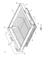
- FIG. 1 is a perspective view of a combined rack according to the first embodiment of the disclosure
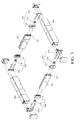
- FIG. 2 is a partial exploded view of FIG. 1
- FIG. 3 is a perspective view of the front plate, the back plate, the left component and the right component of FIG. 2
- FIG. 4 is a partial plan view of the front plate and the carrying component of FIG. 3 .
- the combined rack 10 of this embodiment comprises a front plate 100, a back plate 200, a left component 300, a right component 400 and a carrying component 550.
- the combined rack 10 further comprises two first connecting assemblies 600 and two second connecting assemblies 700.
- the front plate 100, the back plate 200, the left component 300, the right component 400 and the carrying component 550 together form an accommodation space.
- the front plate 100 and the back plate 200 are located on opposite two sides of the carrying component 550 respectively.
- the left component 300 and the right component 400 are located on opposite two sides of the carrying component 550 respectively.
- the left component 300 and the right component 400 is respectively configured for being slidably installed on the two sliding rail 20 which are configured for being fixed to a cabinet (not shown in the figures). Thereby, the combined rack 10 may slide relative to the sliding rail 20 along the extending direction of the left component 300 (namely the direction of arrow a).
- the lower edge of the front plate 100 comprises a front support structure 101 while the lower edge of the back plate 200 comprises a back support structure 201.
- the front support structure 101 and the back support structure 201 are both grooves.
- the carrying component 550 comprises a plurality of front combining components 510 and a plurality of back combining components 520.
- the opposite two sides of the front combining component 510 each comprises a first combining portion 511 and a second combining portion 512.
- the opposite two sides of the back combining component 520 each comprises a third combining portion 521 and a fourth combining portion 522.
- the front plate 100 and the back plate 200 may be hollow plates or solid plates.
- the number of the front combining component 510 and that of the back combining component 520 may both be one.
- the front combining component 510 and the back combining component 520 may be connected to the front plate 100 and the back plate 200.
- the first combining portion 511 and the third combining portion 521 are respectively a block.
- the front support structure 101 and the back support structure 201 (namely two fastening grooves) are fastened with the first combining portion 511 and the third combining portion 521 (namely two blocks).
- the front combining component 510 is disposed on the front support structure 101 of the lower edge of the front plate 100 while the back combining component 520 is disposed on the back support structure 201 of the lower edge of the back plate 200.
- the second combining portion 512 and the fourth combining portion 522 are respectively a hook.
- the carrying member 500 is a rack consisting of a plurality of rods while opposite two sides of the carrying member 500 comprises a rod 530 respectively.
- the two rods 530 are hooked at the second combining portion 512 and the fourth combining portion 522 (namely two hooks) respectively.
- the two first connecting assemblies 600 each comprise a first connecting member 610, a second connecting member 620 and a first fixing member 630.
- the two first connecting members 610 are disposed on opposite two ends of the front plate 100.
- the two second connecting members 620 are disposed on the left component 300 and the right component 400 respectively and are movably combined with the two first connecting members 610 respectively.
- the two first fixing members 630 are respectively pivoted on the two first connecting members 610.
- the first fixing member 630 may move relative to the first connecting member 610 and therefore has a fixed position and an adjusted position.
- the first fixing member 630 at the fixed position is used for fixing the relative position between the first connecting member 610 and the second connecting member 620 while the first fixing member 630 at the adjusted position is for releasing the fastening connection between the first connecting member 610 and the second connecting member 620 so that it may adjust the relative position of the first connecting member 610 and the second connecting member 620.
- the two second connecting assemblies 700 each comprises a third connecting member 710, a fourth connecting member 720 and a second fixing member 730.
- the two third connecting members 710 are disposed on opposite two ends of the back plate 200 respectively.
- the two third connecting members 710 are disposed on opposite two ends of the back plate 200.
- the two fourth connecting members 720 are disposed on the left component 300 and the right component 400 respectively.
- the two fourth connecting members 720 are movably combined with the two third connecting members 710 respectively.
- the two second fixing member 730 are pivoted on the two third connecting members 710 respectively.
- the second fixing member 730 is configured for moving relative to the third connecting member 710 and thus has a fixed position and an adjusted position.
- the second fixing member 730 at the fixed position is used for fixing the relative position between the third connecting member 710 and the fourth connecting member 720 while the second fixing member 730 at the adjusted position is for releasing the fastening connection between the third connecting member 710 and the fourth connecting member 720 so that it may adjust the relative position of the first connecting member 610 and the second connecting member 620. Thereby, the width between the left component 300 and the right component 400 can be adjusted.
- first connecting assemblies 600 and the second connecting assemblies 700 are disposed on the front plate 100 and the back plate 200 respectively, but the disclosure is not limited thereto. In other embodiments, the first connecting assemblies 600 and the second connecting assemblies 700 may sleeve on outside of the front plate 100 and the back plate 200.
- the support grooves for the carrying component 550 to combine with is disposed on the left component 300 and the right component 400.
- the left component 300 and the right component 400 are not combined with the carrying component 550.
- the combined rack 10 is not limited by the size of the carrying component 550.
- users may adjust the width between the left component 300 and the right component 400 to fully utilize the accommodation space of the combined rack 10.
- the package size of the combined rack 10 can be minimized for reducing packaging and shipping costs of the combined rack 10.
- FIG. 4 the first combining portion 511 and the third combining portion 521 are respectively a block while the front support structure 101 and the back support structure 201 are fastening grooves but the disclosure is not limited thereto. In other embodiments, these components can be designed as fastening structures matching each other, which is shown in FIG. 5.
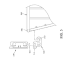
- FIG. 5 is a partial plan view of the front plate and the carrying component according to the second embodiment of the disclosure. As seen in FIG. 5 , this embodiment is similar to that of FIG. 4 and only the meaningful differences will be illustrated. Besides, the change of the front combining component 510 and the back combining component 520 are similar so only the change of the front combining component 510 will be illustrated.
- the carrying component 550 comprises a front combining component 510 and a back combining component 520.
- the opposite two sides of the front combining component 510 comprises a first combining portion 511 and a second combining portion 512 respectively.
- the first combining portion 511 is a fastening groove and the front support structure 101 and the back support structure 201 are both blocks.
- the front support structure 101 is fastened with the first combining portion 511 so that the front combining component 510 and the front plate 100 are combined with each other.
- the first combining portion 511 may be a hook.
- FIG. 6 is a partial plan view of the front plate and the carrying component according to the third embodiment of the disclosure. As seen in FIG. 6 , this embodiment is similar to that of FIG. 4 and only the meaningful differences will be illustrated. Besides, the change of the front combining component 510 and the back combining component 520 are similar so only the change of the front combining component 510 will be illustrated.
- the carrying component 550 comprises the front combining component 510 and the back combining component 520.
- the opposite two sides of the front combining component 510 comprises a first combining portion 511 and a second combining portion 512 respectively.
- the first combining portion 511 is a hook and the front support structure 101 and the back support structure 201 are both fastening grooves.
- the front support structure 101 is fastened with the first combining portion 511 (the hook).
- the second combining portion 512 of the front combining component 510 is fixed to the carrying member 500 by welding, but it is not limited thereto. In other embodiment, the second combining portion 512 of the front combining component 510 may be fixed to the carrying member 500 by screwing.
- front combining component 510 and the carrying member 500 mentioned before are not integrally formed and the back combining component 520 and the carrying member 500 mentioned before are not integrally formed, the disclosure is not limited thereto. In other embodiments, the front combining component 510 and the back combining component 520 may be integrally connected to the opposite two sides of the carrying member 500 respectively.
- FIG. 7 is a partial plan view of the front plate and the carrying component according to the fourth embodiment of the disclosure.
- the combined rack 10 of this embodiment comprises a front plate 100, a back plate 200, a left component 300, a right component 400 and a carrying component 550.
- the front plate 100, the back plate 200, the left component 300, the right component 400 and the carrying component 550 together form an accommodation space.
- the lower edge of the front plate 100 comprises a front support structure 101 while the lower edge of the back plate 200 comprises a back support structure 201.
- the carrying member 500 comprises a carrying member 500, a front combining component 510 and a back combining component 520.
- the opposite two sides of the carrying component 550 are installed on the front support structure 101 and the back support structure 201 respectively.
- the front support structure 101 and the back support structure 201 are grooves (or fastening grooves), and the carrying component 550 is a storage box.
- the front combining component 510 on the front side of the carrying component 550 and the back combining component 520 on the back side of the carrying component 550 are installed on the front support structure 101 and the back support structure 201, but the disclosure is not limited thereto.
- the carrying component 550 may be a plate or a basket.
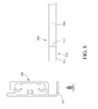
- FIG. 8 is a partial plan view of the front plate and the carrying component according to the fifth embodiment of the disclosure.
- the carrying component 550 is a plate and comprises a carrying member 500, a front combining component 510 and a back combining component 520.
- the front side and the back side of the carrying member 500 are connected to the front combining component 510 and the back combining component 520 respectively.
- the lower edges of the front plate 100 and the back plate 200 comprise a front support structure 101 and a back support structure 201 respectively.
- the front combining component 510 and the back combining component 520 are installed on the front support structure 101 and the back support structure 201 respectively but they are not limited thereto.
- the front support structure 101 and the back support structure 201 are support sheets.
- the structure of the back plate can be different from that of the front plate but both of them have support grooves on their bottom parts for the carrying component to be installed on.
- the support structure for carrying component to be installed on are now moved to the bottom parts of front and back components. Thereby, the left and right components are no longer combined with the carrying component.
- the combined rack is not limited by the size of the carrying component. In other words, users may adjust the width between the left and right components easily to fully utilize the accommodation space of the combined rack.
- the package size thereof can be minimized for reducing the packaging and shipping costs.
Landscapes
- Assembled Shelves (AREA)
- Drawers Of Furniture (AREA)
Applications Claiming Priority (1)
| Application Number | Priority Date | Filing Date | Title |
|---|---|---|---|
| TW102110978A TWI538639B (zh) | 2013-03-27 | 2013-03-27 | 組合式架體 |
Publications (1)
| Publication Number | Publication Date |
|---|---|
| EP2783597A1 true EP2783597A1 (de) | 2014-10-01 |
Family
ID=49696997
Family Applications (1)
| Application Number | Title | Priority Date | Filing Date |
|---|---|---|---|
| EP20140161673 Withdrawn EP2783597A1 (de) | 2013-03-27 | 2014-03-26 | Kombinationsregal |
Country Status (5)
| Country | Link |
|---|---|
| US (1) | US9468293B2 (de) |
| EP (1) | EP2783597A1 (de) |
| JP (1) | JP3194589U (de) |
| CN (2) | CN203328281U (de) |
| TW (1) | TWI538639B (de) |
Families Citing this family (20)
| Publication number | Priority date | Publication date | Assignee | Title |
|---|---|---|---|---|
| TWI538639B (zh) * | 2013-03-27 | 2016-06-21 | 世塑有限公司 | 組合式架體 |
| US9788667B2 (en) * | 2013-07-16 | 2017-10-17 | Fasteners For Retail, Inc. | Lock for securing front rail to wire shelving |
| US20150208801A1 (en) * | 2014-01-26 | 2015-07-30 | Yajun Hu | Slidable storage container and sliding mechanism |
| MX349715B (es) * | 2014-12-17 | 2017-08-09 | Mabe Sa De Cv | Cajón deslizable. |
| US9642457B1 (en) * | 2015-06-25 | 2017-05-09 | Smead Manufacturing Company | Adjustable frame for hanging folders |
| US10709238B1 (en) * | 2015-07-24 | 2020-07-14 | Richard Simon Thompson | Shelf system improvements |
| CN106466059A (zh) * | 2015-08-14 | 2017-03-01 | 世塑有限公司 | 组合抽屉 |
| US9596931B1 (en) * | 2016-04-18 | 2017-03-21 | Clairson, Inc. | Basket and rail assemblies |
| USD814189S1 (en) | 2016-03-04 | 2018-04-03 | Clairson, Inc. | Basket |
| USD845746S1 (en) | 2016-04-18 | 2019-04-16 | Clairson, Inc. | Basket holder |
| WO2018125545A1 (en) * | 2016-12-30 | 2018-07-05 | Wal-Mart Stores, Inc. | Interchangeable modular shelf system |
| US10426315B2 (en) * | 2017-02-21 | 2019-10-01 | Whirlpool Corporation | Dishwasher |
| TWM551449U (zh) * | 2017-05-24 | 2017-11-11 | Shen Hao Metal Working Co Ltd | 網籃式抽屜結構 |
| CN109567448A (zh) * | 2018-10-11 | 2019-04-05 | 世塑有限公司 | 组合式抽屉 |
| US10874213B2 (en) | 2019-01-15 | 2020-12-29 | Tag Hardware Systems Ltd. | Drawer system |
| CN112006432A (zh) * | 2019-05-29 | 2020-12-01 | 3M创新有限公司 | 置物单元及包括所述置物单元的置物架 |
| US10905236B1 (en) | 2019-09-16 | 2021-02-02 | Trinity International Industries, L.L.C. | Wire shelf |
| US11044993B2 (en) * | 2019-09-16 | 2021-06-29 | Trinity International Industries, L.L.C. | Ladder mount assembly for shelving |
| CN113995245A (zh) * | 2021-02-26 | 2022-02-01 | 士商湖州五金机电有限公司 | 一种宽度可无级调节伸缩篮 |
| TWI762379B (zh) * | 2021-07-09 | 2022-04-21 | 永山實業股份有限公司 | 組合式置物層架之籃體軌道組裝結構 |
Citations (5)
| Publication number | Priority date | Publication date | Assignee | Title |
|---|---|---|---|---|
| FR2021794A1 (de) * | 1968-10-29 | 1970-07-24 | Schock & Co Gmbh | |
| DE8612821U1 (de) * | 1986-05-10 | 1986-06-26 | Emsa-Werke Wulf GmbH & Co, 4407 Emsdetten | Lade mit rechteckiger Grundfläche und wenigstens einer aufragenden, einen Handgriff aufweisenden Stirnwand |
| US20050001522A1 (en) * | 2003-07-01 | 2005-01-06 | Ulike Corporation | Basket frame |
| KR20110086119A (ko) * | 2008-10-23 | 2011-07-27 | 파울 헤티히 게엠베하 운트 콤파니 카게 | 서랍, 및 서랍 바닥을 단단히 클램핑하기 위한 도구 |
| US20110304249A1 (en) * | 2010-06-09 | 2011-12-15 | Hsiu-Chen Lai | Modular drawer box structure |
Family Cites Families (30)
| Publication number | Priority date | Publication date | Assignee | Title |
|---|---|---|---|---|
| US2635779A (en) * | 1949-06-02 | 1953-04-21 | Philco Corp | Storage apparatus |
| US4527694A (en) * | 1982-05-27 | 1985-07-09 | Bolt William S | Suspendable hanger framework assembly |
| US4807764A (en) * | 1987-08-27 | 1989-02-28 | Tamara Bellin | System for mounting articles under a downwardly facing surface |
| DE4032426C2 (de) * | 1990-10-12 | 1999-04-08 | Lautenschlaeger Mepla Werke | Halterungsbeschlag für Schubladen-Ausziehführungen |
| US5205630A (en) * | 1991-04-05 | 1993-04-27 | Intermetro Industries Corporation | Multiple purpose, knock-down modular storage system and method of assembling same |
| US5405020A (en) * | 1993-12-23 | 1995-04-11 | Fotioo; Bobby | Adjustable hanging file frame system |
| US5515980A (en) * | 1993-12-23 | 1996-05-14 | B & L Products, Inc. | Dimensionally variable hanging file frame system |
| DE4432820B4 (de) * | 1994-09-15 | 2007-03-22 | MEPLA-WERKE LAUTENSCHLäGER GMBH & CO. KG | Beschlag zur Höhenverstellung von Schubladen |
| US6166916A (en) * | 1997-11-14 | 2000-12-26 | Unitrend, Inc. | Adjustable circuit board support frame |
| TW395406U (en) | 1998-07-08 | 2000-06-21 | Tsai Jian Ting | Improvement in rotating structure of a duster |
| TW414139U (en) | 1999-06-17 | 2000-12-01 | Lin Chuen Mei | Improved screwdriver handle structure |
| US6443544B1 (en) * | 2000-05-23 | 2002-09-03 | Astoria Industries Of Iowa, Inc. | Slidable drawer for utility vehicle |
| TW444799U (en) | 2000-07-06 | 2001-07-01 | Li Guan Shiuan | Improved gate control device |
| US6491173B1 (en) * | 2000-07-18 | 2002-12-10 | Sidelines, Inc. | Wire basket system |
| US6578720B1 (en) * | 2002-02-08 | 2003-06-17 | I Jang Industrial Co., Ltd. | Rack comprising adjustable slide rails |
| US7497533B2 (en) * | 2003-04-28 | 2009-03-03 | Clairson, Inc. | Shelves, resilient drawer stops, and drawer brackets for supporting shelves and drawers |
| TW571687U (en) | 2003-06-05 | 2004-01-11 | Ulike Corp | Structure of placement frame |
| DE202004005475U1 (de) * | 2004-04-02 | 2004-07-01 | Paul Hettich Gmbh & Co. | Tragboden eines Küchengerätes |
| US7108143B1 (en) * | 2005-03-11 | 2006-09-19 | Ruei-Hsing Lin | Sliding rail assembly for wire basket |
| US20070235401A1 (en) * | 2006-03-29 | 2007-10-11 | Costa Charles A | Organizational basket and covering |
| US7597203B2 (en) * | 2007-03-19 | 2009-10-06 | Victor Jasniy | Storage system |
| US7832568B2 (en) * | 2008-04-30 | 2010-11-16 | John-Ching Wu | Cup rack |
| US8590992B2 (en) * | 2009-06-22 | 2013-11-26 | Samsung Electronics Co., Ltd. | Refrigerator |
| US8671712B2 (en) * | 2010-03-25 | 2014-03-18 | Whirlpool Corporation | Upper freezer basket guided by lower freezer basket divider |
| CN202457299U (zh) * | 2011-11-04 | 2012-10-03 | 宝利丰有限公司 | 一种可调节的盛物拉篮 |
| CN102342675B (zh) * | 2011-11-11 | 2013-05-29 | 伍志勇 | 抽屉滑轨反推控制装置 |
| US8782962B1 (en) * | 2012-03-30 | 2014-07-22 | Marshall Dean Schoewe | System and method for suspending storage containers |
| CN202604154U (zh) * | 2012-04-16 | 2012-12-19 | 东莞市华立实业股份有限公司 | 一种橱柜裙板 |
| TWI538639B (zh) * | 2013-03-27 | 2016-06-21 | 世塑有限公司 | 組合式架體 |
| US8960822B1 (en) * | 2013-12-05 | 2015-02-24 | Yen-Huang Hsu | Drawer track with anti-slip structure |
-
2013
- 2013-03-27 TW TW102110978A patent/TWI538639B/zh not_active IP Right Cessation
- 2013-05-14 CN CN2013202620495U patent/CN203328281U/zh not_active Expired - Fee Related
- 2013-05-14 CN CN201310178047.2A patent/CN104068656B/zh not_active Expired - Fee Related
-
2014
- 2014-03-26 EP EP20140161673 patent/EP2783597A1/de not_active Withdrawn
- 2014-03-27 US US14/227,817 patent/US9468293B2/en not_active Expired - Fee Related
- 2014-05-27 JP JP2014002745U patent/JP3194589U/ja not_active Expired - Fee Related
Patent Citations (5)
| Publication number | Priority date | Publication date | Assignee | Title |
|---|---|---|---|---|
| FR2021794A1 (de) * | 1968-10-29 | 1970-07-24 | Schock & Co Gmbh | |
| DE8612821U1 (de) * | 1986-05-10 | 1986-06-26 | Emsa-Werke Wulf GmbH & Co, 4407 Emsdetten | Lade mit rechteckiger Grundfläche und wenigstens einer aufragenden, einen Handgriff aufweisenden Stirnwand |
| US20050001522A1 (en) * | 2003-07-01 | 2005-01-06 | Ulike Corporation | Basket frame |
| KR20110086119A (ko) * | 2008-10-23 | 2011-07-27 | 파울 헤티히 게엠베하 운트 콤파니 카게 | 서랍, 및 서랍 바닥을 단단히 클램핑하기 위한 도구 |
| US20110304249A1 (en) * | 2010-06-09 | 2011-12-15 | Hsiu-Chen Lai | Modular drawer box structure |
Also Published As
| Publication number | Publication date |
|---|---|
| TW201436739A (zh) | 2014-10-01 |
| CN104068656B (zh) | 2016-12-28 |
| TWI538639B (zh) | 2016-06-21 |
| US9468293B2 (en) | 2016-10-18 |
| CN104068656A (zh) | 2014-10-01 |
| CN203328281U (zh) | 2013-12-11 |
| US20140291266A1 (en) | 2014-10-02 |
| JP3194589U (ja) | 2014-12-04 |
Similar Documents
| Publication | Publication Date | Title |
|---|---|---|
| EP2783597A1 (de) | Kombinationsregal | |
| US9560786B2 (en) | Slide rail assembly and slide rail assembly pair | |
| US9167896B1 (en) | Supporting rack assembly | |
| US9629462B2 (en) | Modular drawer structure | |
| US10167981B2 (en) | Extension-type cable tie frame for power cable | |
| US20160165739A1 (en) | Server | |
| US20180063987A1 (en) | Cable management device | |
| CN103259196A (zh) | 一种配电盘或配电箱的框架 | |
| TWD174995S (zh) | 書架 | |
| TW201709803A (zh) | 整合可移動及可鎖固之導軌及伺服器機架 | |
| RU2017101564A (ru) | Расширяемая конструкция для хранения | |
| US9846460B2 (en) | Server system and limiting mechanism used thereby | |
| CN103547107A (zh) | 支撑装置 | |
| KR20130115405A (ko) | 슬라이딩 이중책장 | |
| CN104352087B (zh) | 新型可变组合办公桌 | |
| JP5930461B2 (ja) | 仕切板取付装置 | |
| CN204071440U (zh) | 落地屏风 | |
| JP2015510799A (ja) | 家具引出し | |
| KR200474593Y1 (ko) | 경량 시스템 서랍장 | |
| EP2873353A3 (de) | Zusammenklappbares Gestell, insbesondere für Messezwecke | |
| US8590988B2 (en) | Lower corner cabinet | |
| KR200482790Y1 (ko) | 적층 조립식 서가 | |
| KR20110009775A (ko) | 책상판에 설치 및 분리가 편리한 책꽂이 틀 | |
| WO2016132306A3 (en) | Modular cabinet structure | |
| US20100071295A1 (en) | Bamboo panel assembly |
Legal Events
| Date | Code | Title | Description |
|---|---|---|---|
| 17P | Request for examination filed |
Effective date: 20140326 |
|
| AK | Designated contracting states |
Kind code of ref document: A1 Designated state(s): AL AT BE BG CH CY CZ DE DK EE ES FI FR GB GR HR HU IE IS IT LI LT LU LV MC MK MT NL NO PL PT RO RS SE SI SK SM TR |
|
| AX | Request for extension of the european patent |
Extension state: BA ME |
|
| PUAI | Public reference made under article 153(3) epc to a published international application that has entered the european phase |
Free format text: ORIGINAL CODE: 0009012 |
|
| R17P | Request for examination filed (corrected) |
Effective date: 20150123 |
|
| RBV | Designated contracting states (corrected) |
Designated state(s): AL AT BE BG CH CY CZ DE DK EE ES FI FR GB GR HR HU IE IS IT LI LT LU LV MC MK MT NL NO PL PT RO RS SE SI SK SM TR |
|
| 17Q | First examination report despatched |
Effective date: 20150609 |
|
| STAA | Information on the status of an ep patent application or granted ep patent |
Free format text: STATUS: THE APPLICATION IS DEEMED TO BE WITHDRAWN |
|
| 18D | Application deemed to be withdrawn |
Effective date: 20160614 |