US9846460B2 - Server system and limiting mechanism used thereby - Google Patents

Server system and limiting mechanism used thereby Download PDF

Info

Publication number
US9846460B2
US9846460B2 US15/366,572 US201615366572A US9846460B2 US 9846460 B2 US9846460 B2 US 9846460B2 US 201615366572 A US201615366572 A US 201615366572A US 9846460 B2 US9846460 B2 US 9846460B2
Authority
US
United States
Prior art keywords
limiting
server
sliding
server case
case
Prior art date
Legal status (The legal status is an assumption and is not a legal conclusion. Google has not performed a legal analysis and makes no representation as to the accuracy of the status listed.)
Active
Application number
US15/366,572
Other versions
US20170177040A1 (en
Inventor
Chengwang ZHAO
Bingwei PENG
Zhifeng ZHU
Current Assignee (The listed assignees may be inaccurate. Google has not performed a legal analysis and makes no representation or warranty as to the accuracy of the list.)
Inventec Pudong Technology Corp
Inventec Corp
Original Assignee
Inventec Pudong Technology Corp
Inventec Corp
Priority date (The priority date is an assumption and is not a legal conclusion. Google has not performed a legal analysis and makes no representation as to the accuracy of the date listed.)
Filing date
Publication date
Application filed by Inventec Pudong Technology Corp, Inventec Corp filed Critical Inventec Pudong Technology Corp
Publication of US20170177040A1 publication Critical patent/US20170177040A1/en
Assigned to INVENTEC CORPORATION, INVENTEC TECHNOLOGY CO., LTD reassignment INVENTEC CORPORATION ASSIGNMENT OF ASSIGNORS INTEREST (SEE DOCUMENT FOR DETAILS). Assignors: PENG, BINGWEI, ZHAO, CHENGWANG, ZHU, ZHIFENG
Application granted granted Critical
Publication of US9846460B2 publication Critical patent/US9846460B2/en
Active legal-status Critical Current
Anticipated expiration legal-status Critical

Links

Images

Classifications

    • GPHYSICS
    • G06COMPUTING; CALCULATING OR COUNTING
    • G06FELECTRIC DIGITAL DATA PROCESSING
    • G06F1/00Details not covered by groups G06F3/00 - G06F13/00 and G06F21/00
    • G06F1/16Constructional details or arrangements
    • G06F1/18Packaging or power distribution
    • G06F1/181Enclosures
    • GPHYSICS
    • G06COMPUTING; CALCULATING OR COUNTING
    • G06FELECTRIC DIGITAL DATA PROCESSING
    • G06F1/00Details not covered by groups G06F3/00 - G06F13/00 and G06F21/00
    • G06F1/16Constructional details or arrangements
    • G06F1/18Packaging or power distribution
    • G06F1/183Internal mounting support structures, e.g. for printed circuit boards, internal connecting means
    • G06F1/187Mounting of fixed and removable disk drives
    • HELECTRICITY
    • H05ELECTRIC TECHNIQUES NOT OTHERWISE PROVIDED FOR
    • H05KPRINTED CIRCUITS; CASINGS OR CONSTRUCTIONAL DETAILS OF ELECTRIC APPARATUS; MANUFACTURE OF ASSEMBLAGES OF ELECTRICAL COMPONENTS
    • H05K7/00Constructional details common to different types of electric apparatus
    • H05K7/14Mounting supporting structure in casing or on frame or rack
    • H05K7/1485Servers; Data center rooms, e.g. 19-inch computer racks
    • H05K7/1488Cabinets therefor, e.g. chassis or racks or mechanical interfaces between blades and support structures
    • H05K7/1489Cabinets therefor, e.g. chassis or racks or mechanical interfaces between blades and support structures characterized by the mounting of blades therein, e.g. brackets, rails, trays

Landscapes

  • Engineering & Computer Science (AREA)
  • Computer Hardware Design (AREA)
  • General Engineering & Computer Science (AREA)
  • Theoretical Computer Science (AREA)
  • Microelectronics & Electronic Packaging (AREA)
  • Power Engineering (AREA)
  • Human Computer Interaction (AREA)
  • Physics & Mathematics (AREA)
  • General Physics & Mathematics (AREA)
  • Drawers Of Furniture (AREA)

Abstract

The present invention provides a server system and a limiting mechanism used thereby. Through mutual cooperation between the limiting mechanism which sets on a server rack and sliding grooves and limiting holes which are formed in outer side walls of a server case, when internal components of the server case are drawn out, a rear end of the server case can be effectively prevented from turning up or falling down, the problem of case fixation when the server rack uses a tray type sliding rail is solved, the structure is simple and reliable and the practicability is very high.

Description

BACKGROUND OF THE PRESENT INVENTION
Field of Invention
The present invention relates to the field of servers, in particular to a server system and a limiting mechanism used thereby.
Description of Related Arts
With respect to the existing server, in order to facilitate the maintenance of a server case, the server case is placed on sliding rails of a server rack to draw the server case out of the server rack at any time. However, the sliding rails of the server rack usually play a role of bearing loads and cannot prevent the case from moving in an upward direction. When the case is placed on the sliding rails, the rear half portion of the case is in a non-fixed state. In addition, the internal structures of partial servers can be drawn out. When the server is in a state that the internal structure is drawn out, since a great amount of hard disk modules are mounted at the front portion of the server case, the weight of the front portion of the server case is heavier, the situation of overall imbalance is caused and the rear portion thereof has a trend of uplifting. If a downward force is slightly applied to the drawn-out modules at this moment, the case is possibly caused to be turned over. If a machine exists above the case at this moment, collision will be caused. Both these two situations may cause injuries to users and damages to the machine.
SUMMARY
the present invention provides a limiting mechanism, which is applied to a server system, wherein the server system has a server rack and a server case, the server rack comprises sliding rails, the sliding rails are oppositely arranged on two sides of the server rack, and the server case is slidably arranged on the sliding rails; and wherein the mechanism comprises limiting piece, slidably setting on the sliding rails, equipped with a convex part on a side surface of the limiting piece towards the server case, equipped with a first barrier portion on a side of the limiting piece towards a rear end of the sliding rail to limit the limiting piece sliding out of the sliding rail; sliding groove formed in outer side wall of the server case and located at rear end of the outer side wall of the server case, one end of the sliding groove connecting to rear end surfaces of the outer side wall of the server case for sliding the convex part into the sliding groove; and limiting hole formed in the outer side walls of the server case and located at the other ends of the sliding grooves, the shape of the limiting holes matching with the shape of the convex part, to allow the convex parts to be buckled in the limiting holes, wherein when the server case is mounted on the server rack along the sliding rails, the limiting pieces are driven to relatively slide on the sliding rails, and the convex parts slide along the sliding grooves and are clamped in the limiting holes to realize limitation in a vertical direction to limit the movement of the server case in the vertical direction.
BRIEF DESCRIPTION OF THE DRAWINGS
FIG. 1 illustrates a side view of a limiting piece of the present invention in one specific embodiment.
FIG. 2 illustrates a schematic application view of a limiting piece of the present invention in one specific embodiment.
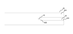
FIG. 3 illustrates a side view of a server case of the present invention in one specific embodiment.
FIG. 4 illustrates a schematic application view of a server system of the present invention in one specific embodiment.
DESCRIPTION OF COMPONENT MARK NUMBERS
1 Limiting mechanism
11 Limiting piece
111 Convex part
112 Barrier portion
113 Limiting part
114 Elastic clamping hook
115 Supporting portion
116 Connecting portion
117 Fixing hole
12 Sliding groove
121 Notch
122 Notch
13 Limiting hole
2 Server rack
21 Sliding rail
3 Sever
31 Server case
311 Outer side wall
32 Second hard disk component
DETAILED DESCRIPTION
The implementation mode of the present invention will be described below through specific embodiments. One skilled in the art can easily understand other advantages and effects of the present invention according to contents disclosed by the description. The present invention can also be implemented or applied through other different specific implementation modes. Various modifications or changes can also be made to all details in the description based on different points of view and applications without departing from the spirit of the present invention. It needs to be stated that the following embodiments and the features in the embodiments can be combined with one another under the situation of no conflict.
It needs to be stated that the drawings provided in the following embodiments are just used for schematically describing the basic concept of the present invention, thus only illustrate components only related to the present invention and are not drawn according to the numbers, shapes and sizes of components during actual implementation, the configuration, number and scale of each component during actual implementation thereof may be freely changed, and the component layout configuration thereof may be more complex.
In a large-size server system, a plurality of servers can be arranged on a server rack in a cascade manner through sliding rails. In addition, the internal components of partial servers (such as hard disk components of storage servers) can be drawn out and consequently the weight of one end of the server is caused to be obviously higher than the weight of the other end. However, the sliding rails of the existing rack basically only play a role of supporting and bearing the server. As a result, when the stress of the two ends of the server is caused to be seriously imbalanced due to drawing of the internal components, the rear end of the server easily turns up, possibly strikes the server in an adjacent upper layer and thereby causes the server to be damaged, or slides out of the rack, causes the server to be damaged and influence the personnel safety of working personnel. Therefore, the server which is arranged on the server rack needs to be flexibly fixed to prevent the above-mentioned adverse situations from occurring. By arranging a limiting mechanism in the server system, the present invention can better solve the above-mentioned problems.
Specifically, please refer to FIGS. 1-4, wherein FIG. 1 illustrates a side view of a limiting piece of the present invention in one specific embodiment; FIG. 2 illustrates a schematic application view of a limiting piece of the present invention in one specific embodiment; FIG. 3 illustrates a side view of a server case of the present invention in one specific embodiment; and FIG. 4 illustrates a schematic application view of a server system of the present invention in one specific embodiment.
The limiting mechanism 1 is applied to a server system, wherein the server system has a server rack 2 and a server 3 as shown in FIG. 4, the server 3 has a server case 31, the server rack 2 comprises sliding rails 21, the sliding rails 21 are oppositely arranged on two sides of the server rack 2 and the server case 31 is slidably arranged on the sliding rails 21, and the mechanism 1 comprises limiting pieces 11, sliding grooves 12 and limiting holes 13.
The limiting piece 11 slidably sets on the sliding rails 21, specifically as shown in FIG. 2, the sliding rail 21 in FIG. 2 is a portion of the sliding rails 21 of the server rack 2 in the server system, the limiting piece 11 is equipped with a convex part 111 on a side surface of the limiting piece towards the server case 31 and specifically is equipped with a first barrier portion 112 on a side of the limiting piece towards a rear end of the sliding rail 21 to limit the limiting piece 11 sliding out of the sliding rail 21.
Referring to FIG. 3, the sliding groove 12 is formed in outer side wall 311 of the server case 31 and are located at rear end of the outer side wall 311 of the server case 31, one end of the sliding groove 12 connected to the rear end surfaces of the outer side wall 311 of the server case for sliding the convex part 111 to slide into the sliding groove 12. The limiting hole 13 is formed in the outer side walls 311 of the server case 31 and is located at the other ends of the sliding grooves 12, and the shape of the limiting holes 13 matches with the shape of the convex part 111, the convex part is to be buckled the limiting holes.
When the server case 31 is mounted on the server rack 2 along the sliding rails 21, the limiting pieces 11 are driven to relatively slide on the sliding rails 21, and the convex part 111 slide along the sliding grooves 12 and is buckled in the limiting holes 13 to limit the movement of the server case 31 in the vertical direction.
In one specific embodiment of the present invention, each limiting piece 11 further comprises a limiting part 113 and two elastic clamping hooks 114 fixed on the limiting part 113, and the two elastic clamping hooks 114 are arranged on upper and lower sides of the limiting part 113 to allow the limiting piece 11 to slidably set on the sliding rail 21 through the two elastic clamping hooks 114.
In one specific embodiment of the present invention, upper and lower sides of the limiting piece 11 are further equipped with two supporting portions 115 respectively corresponding to the two elastic clamping hooks 114, and preferably the two supporting portions 115 are integrally connected with the limiting part 113. When the limiting piece 11 slidably sets on the sliding rail 21, the two supporting portions 115 are clamped on the sliding rail 21 to limit the limiting part from moving up and down relative to the sliding rail 12, so as to prevent the rear end of the server 3 from turning up or the server 3 from falling down when the internal components of the server 3 are drawn out and the drawn-out components are subjected to a downward pressing force, and to guarantee the safety of the system.
In one specific embodiment of the present invention, the two supporting portions 115 are respectively located on inner sides of the two elastic clamping hooks 114, and the elastic clamping hooks 113 are buckling in the sliding rail 12 through the two supporting portions 115 and thereby are buckled. This design can effectively facilitate the limiting piece 11 to be fixed on the rack 2 and facilitate the mounting. In other embodiments, the two supporting portions 115 can also be respectively located on the outer sides of the two elastic clamping hooks 114. Further, the two elastic clamping hooks 114 are connected with the limiting part through a connecting portion 116. In addition, preferably, the connecting portion 116 and the limiting part 113 are respectively equipped with fixing holes to connect each other through rivets.
In one specific embodiment of the present invention, each convex part 111 is a rivet part riveted to the corresponding hole of the limiting piece 11, the rivet part comprises a rivet cap and a rivet head, the rivet cap penetrates through the corresponding fixing hole 117 of the limiting piece 11 to connect the limiting part 113 and the rivet head is exposed out of one side of the limiting piece 11 towards the server case 31 to fit with the sliding groove 12 formed in the outer side wall 311 of the server case 31.
In one specific embodiment of the present invention, the diameter of the rivet head is smaller than the width of the sliding groove 12 and is not greater than the diameter of the limiting hole 13, such that the convex part 111 slides from the notch of one end of the sliding groove 12 to the other end of the sliding groove 12 and is buckled in the limiting hole 13 through the rivet head to limit the movement of the server case 31 in the vertical direction.
In one specific embodiment of the present invention, the server 3 further comprises a first hard disk component (not shown) and a second hard disk component 32 as shown in FIG. 4 (the first hard disk component and the second hard disk component 32 are the internal components of the server 3, and of course, it can be understood that, in other embodiments, the internal components of the server 3 can also be other functional components). In addition, FIG. 4 respectively illustrates the limiting piece 11 covered by the components and the cooperative arrangement of the limiting piece 11 and the server case 31 by using circles to facilitate understanding. The first hard disk component is slidably connected with the inner wall of the server case 31 through a first sliding rail component (not shown); the second hard disk component 32 is slidably connected with the first hard disk component through a second sliding component, the second hard disk component 32 and the first hard disk component are located in parallel in the server case 32, and the second hard disk component 32 is located at an outlet of the server case 3; and the shape of the limiting holes 13 matches with the shape of the convex parts 111 to allow the convex parts 111 to be clamped in the limiting holes 13 when the first hard disk component and the second hard disk component 32 slide out of the server case 31.
To sum up, in the server system and the limiting mechanism used thereby provided by the present invention, through mutual cooperation between the limiting mechanism which sets on the server rack and the sliding grooves and the limiting holes which are formed in outer side walls of the server case, when internal components of the server case 31 are drawn out, the rear end of the server case 31 can be effectively prevented from turning up or falling down, the problem of case fixation when the server rack uses a tray type sliding rail 21 is solved, the structure is simple and reliable and the practicability is very high.
The above-mentioned embodiments are just used for exemplarily describing the principle and effects of the present invention instead of limiting the present invention. One skilled in the art can make modifications or changes to the above-mentioned embodiments without going against the spirit and the range of the present invention. Therefore, all equivalent modifications or changes made by those who have common knowledge in the art without departing from the spirit and technical concept disclosed by the present invention shall be still covered by the claims of the present invention.

Claims (10)

What is claimed is:
1. A limiting mechanism, applied to a server system, the server system having a server rack and a server case, the server rack comprising sliding rails, the sliding rails being oppositely arranged on two sides of the server rack, and the server case being slidably arranged on the sliding rails, and wherein the mechanism comprises:
limiting piece, slidably sitting on the sliding rails, equipped with a convex part on a side surface of the limiting piece towards the server case, equipped with a first barrier portion on a side of the limiting piece towards a rear end of the sliding rail to limit the limiting piece sliding out of the sliding rail;
sliding groove, formed in outer side wall of the server case and located at rear end of the outer side wall of the server case, one end of the sliding groove connecting to the rear end surfaces of the outer side wall of the server case for sliding the convex part into the sliding groove; and
limiting hole, formed in the outer side walls of the server case and located at another end of the sliding grooves, the shape of the limiting holes matching with the shape of the convex part, the convex part to be buckled the limiting holes;
wherein when the server case is mounted on the server rack along the sliding rails, the limiting pieces are driven to relatively slide on the sliding rails, and the convex part slides along the sliding grooves and is buckled in the limiting holes to limit the vertical movement of the server case.
2. The limiting mechanism according to claim 1, wherein the limiting piece further comprises a limiting part and two elastic clamping hooks fixed on the limiting part, and the two elastic clamping hooks are arranged on upper and lower sides of the limiting part, the limiting piece is slidably set on the sliding rail through the two elastic clamping hooks.
3. The limiting mechanism according to claim 2, wherein upper and lower sides of the limiting piece are equipped with two supporting portions respectively corresponding to the two elastic clamping hooks, the two supporting portions are integrally connected with the limiting part, and when the limiting piece slidably sets on the sliding rail, the two supporting portions are clamped on the sliding rail to limit the vertical movement of the limiting part.
4. The limiting mechanism according to claim 3, wherein the two supporting portions are respectively located on inner sides of the two elastic clamping hooks, and when the limiting piece slidably sets on the sliding rail, the elastic clamping hooks are in buckling connection with the sliding rail.
5. The limiting mechanism according to claim 2, wherein the two elastic clamping hooks are connected with the limiting part through a connecting portion.
6. The limiting mechanism according to claim 5, wherein the connecting portion and the limiting part are respectively equipped with fixing holes to connect each other through rivets.
7. The limiting mechanism according to claim 1, wherein the convex part is a rivet part riveted to the limiting piece, the rivet part comprises a rivet cap and a rivet head, the rivet cap penetrates through the limiting part to connect the limiting part, and the rivet head is exposed out of one side of the limiting piece towards the server case.
8. The limiting mechanism according to claim 7, wherein the diameter of the rivet head is smaller than the width of the sliding groove and is not greater than the diameter of the limiting hole, such that when the convex part slides from the notch of one end of the sliding groove to the other end of the sliding groove, the convex part is buckled in the limiting hole through the rivet head.
9. A server system, wherein the server system comprises a server, a server rack equipped with sliding rails and a limiting device, the server is mounted on the server rack through the sliding rails, and the server comprises:
a server case;
a first hard disk component, slidably connected with an inner wall of the server case through a first sliding rail component;
a second hard disk component, slidably connected with the first hard disk component through a second sliding component, the second hard disk component and the first hard disk component being located in parallel in the server case, and the second hard disk component being located at an outlet of the server case; and the limiting device comprises:
limiting piece, slidably setting on the sliding rails, equipped with a convex part on the side surface of the limiting piece towards the server case, and equipped with a first barrier portion on the side of the limiting piece towards a rear end portion of the sliding rail to limit the limiting piece from sliding out of the sliding rail;
sliding grooves, formed in outer side walls of the server case and located at rear ends of the outer side walls of the server case, one end of the sliding groove connecting to the rear end surfaces of the outer side wall of the server case for sliding the convex part into the sliding groove; and
limiting holes, formed in the outer side walls of the server case and located at another end of the sliding grooves, the shape of the limiting holes matching with the shape of the convex parts to allow the convex parts to be clamped in the limiting holes.
10. The server system according to claim 9, wherein each limiting piece further comprises a limiting part and two elastic clamping hooks fixed on the limiting part, the two elastic clamping hooks are arranged on upper and lower sides of the limiting part, and the limiting piece is slidably set the sliding rail through the two elastic clamping hooks.
US15/366,572 2015-12-17 2016-12-01 Server system and limiting mechanism used thereby Active US9846460B2 (en)

Applications Claiming Priority (2)

Application Number Priority Date Filing Date Title
CN201510956016.4A CN105425919B (en) 2015-12-17 2015-12-17 A kind of server system and its position-limit mechanism of application
CN2015109560164 2015-12-17

Publications (2)

Publication Number Publication Date
US20170177040A1 US20170177040A1 (en) 2017-06-22
US9846460B2 true US9846460B2 (en) 2017-12-19

Family

ID=55504182

Family Applications (1)

Application Number Title Priority Date Filing Date
US15/366,572 Active US9846460B2 (en) 2015-12-17 2016-12-01 Server system and limiting mechanism used thereby

Country Status (2)

Country Link
US (1) US9846460B2 (en)
CN (1) CN105425919B (en)

Families Citing this family (4)

* Cited by examiner, † Cited by third party
Publication number Priority date Publication date Assignee Title
CN108302012A (en) * 2017-01-11 2018-07-20 惠州市唐群座椅科技股份有限公司 The connecting structure of air pump and air valve
CN109327492A (en) * 2017-08-01 2019-02-12 联想企业解决方案(新加坡)有限公司 server identification device and method
CN107783617B (en) * 2017-11-28 2019-09-17 国家电网有限公司 Server support plate safety device
CN109871091B (en) * 2019-02-25 2023-04-25 西安易朴通讯技术有限公司 Hard disk bracket guide rail fixing structure and server

Citations (33)

* Cited by examiner, † Cited by third party
Publication number Priority date Publication date Assignee Title
US20030141791A1 (en) * 2001-12-12 2003-07-31 William Dubon Telescoping slide assembly
US20050052102A1 (en) * 2001-12-06 2005-03-10 Lauchner Craig E. Method for installing a slide assembly for a computer server using dual flat springs
US20090310894A1 (en) * 2008-06-13 2009-12-17 Hong Fu Jin Precision Industry (Shenzhen) Co., Ltd Slide rail
US7712615B2 (en) * 2004-10-15 2010-05-11 King Slide Works Co., Ltd. Support slide assembly for cable management arm
US20120061551A1 (en) * 2010-09-13 2012-03-15 Hon Hai Precision Industry Co., Ltd. Slide rail assembly
US8146756B2 (en) * 2007-04-18 2012-04-03 Jonathan Manufacturing Corporation Universal toolless rack mount bracket
US20120145874A1 (en) * 2010-12-10 2012-06-14 Tyco Electronics Coproration Method and apparatus for mounting rack components on racks
US20120163740A1 (en) * 2010-12-24 2012-06-28 Hon Hai Precision Industry Co., Ltd. Slide rail assembly
US20120170877A1 (en) * 2010-12-30 2012-07-05 Hon Hai Precision Industry Co., Ltd. Slide rail assembly
US8251333B1 (en) * 2011-04-12 2012-08-28 Hong Fu Jin Precision Industry (Shenzhen) Co., Ltd. Supporting apparatus
US20130058033A1 (en) * 2011-09-06 2013-03-07 Hon Hai Precision Industry Co, Ltd. Retention device for data storage module
US20130259411A1 (en) * 2012-04-03 2013-10-03 Jonathan Manufacturing Corporation Dba Jonathan Engineered Solutions Compact slide assemblies
US20140055959A1 (en) * 2011-05-11 2014-02-27 Ion Manda Rack module
US20140226924A1 (en) * 2013-02-08 2014-08-14 Jonathan Manufacturing Corporation Dba Jonathan Engineered Solutions Slide assembly
US20140265784A1 (en) * 2013-01-23 2014-09-18 Dot Hill Systems Corporation Compliant drawer latch assembly
US20140340837A1 (en) * 2013-05-16 2014-11-20 Quanta Computer Inc. Storage array module and hard disk accommodating unit thereof
US20150049429A1 (en) * 2013-08-16 2015-02-19 Wistron Corporation Server mechanism and disk drive module thereof
US20150062801A1 (en) * 2013-08-27 2015-03-05 Hon Hai Precision Industry Co., Ltd. Mounting apparatus for hard disk drive and electronic device with the mounting apparatus
US20150077924A1 (en) * 2013-09-14 2015-03-19 Jean Paul Rauline Chassis for storage devices
US20150092340A1 (en) * 2013-10-01 2015-04-02 Quanta Computer Inc. Server
US9004432B2 (en) * 2010-07-26 2015-04-14 Accuride International Inc. Rotatable housing assembly
US20150181753A1 (en) * 2013-12-20 2015-06-25 Fujitsu Limited Electronic apparatus, rail structure and rack
US20150208802A1 (en) * 2014-01-29 2015-07-30 Nec Corporation Slide rail unit
US20150334868A1 (en) * 2014-10-24 2015-11-19 Advanced Micro Devices, Inc. Apparatus to facilitate orthogonal coupling of a server sled with a server backplane
US9198323B1 (en) * 2014-09-05 2015-11-24 Martas Precision Slide Co., Ltd. Thin server rack rail
US20160135325A1 (en) * 2013-06-18 2016-05-12 Shuiyan CHEN Slide rail assembly and slide rail assembly pair
US20160157377A1 (en) * 2014-11-27 2016-06-02 Fujitsu Limited Rack mount device
US20160262538A1 (en) * 2015-03-12 2016-09-15 King Slide Works Co., Ltd. Slide rail assembly
US20160278234A1 (en) * 2015-03-19 2016-09-22 King Slide Works Co., Ltd. Slide rail assembly
US20160286683A1 (en) * 2015-03-26 2016-09-29 King Slide Works Co., Ltd. Slide rail assembly
US20160369844A1 (en) * 2015-06-16 2016-12-22 Fujitsu Limited Slide rail and electronic apparatus
US20170020024A1 (en) * 2015-07-15 2017-01-19 King Slide Works Co., Ltd. Slide rail assembly
US20170090528A1 (en) * 2015-09-24 2017-03-30 Quanta Computer Inc. Component tray holder with slim side rails

Family Cites Families (4)

* Cited by examiner, † Cited by third party
Publication number Priority date Publication date Assignee Title
CN201025521Y (en) * 2007-03-09 2008-02-20 鸿富锦精密工业(深圳)有限公司 Server frame
TWI511642B (en) * 2012-03-19 2015-12-01 Wistron Corp Server system and fixing mechanism thereof
CN103458645B (en) * 2012-05-29 2016-01-20 华为技术有限公司 Carriage
CN104503548B (en) * 2014-12-03 2017-12-05 英业达科技有限公司 Server

Patent Citations (34)

* Cited by examiner, † Cited by third party
Publication number Priority date Publication date Assignee Title
US20050052102A1 (en) * 2001-12-06 2005-03-10 Lauchner Craig E. Method for installing a slide assembly for a computer server using dual flat springs
US20030141791A1 (en) * 2001-12-12 2003-07-31 William Dubon Telescoping slide assembly
US7712615B2 (en) * 2004-10-15 2010-05-11 King Slide Works Co., Ltd. Support slide assembly for cable management arm
US8146756B2 (en) * 2007-04-18 2012-04-03 Jonathan Manufacturing Corporation Universal toolless rack mount bracket
US20090310894A1 (en) * 2008-06-13 2009-12-17 Hong Fu Jin Precision Industry (Shenzhen) Co., Ltd Slide rail
US9004432B2 (en) * 2010-07-26 2015-04-14 Accuride International Inc. Rotatable housing assembly
US20120061551A1 (en) * 2010-09-13 2012-03-15 Hon Hai Precision Industry Co., Ltd. Slide rail assembly
US20120145874A1 (en) * 2010-12-10 2012-06-14 Tyco Electronics Coproration Method and apparatus for mounting rack components on racks
US20120163740A1 (en) * 2010-12-24 2012-06-28 Hon Hai Precision Industry Co., Ltd. Slide rail assembly
US20120170877A1 (en) * 2010-12-30 2012-07-05 Hon Hai Precision Industry Co., Ltd. Slide rail assembly
US8251333B1 (en) * 2011-04-12 2012-08-28 Hong Fu Jin Precision Industry (Shenzhen) Co., Ltd. Supporting apparatus
US20140055959A1 (en) * 2011-05-11 2014-02-27 Ion Manda Rack module
US20130058033A1 (en) * 2011-09-06 2013-03-07 Hon Hai Precision Industry Co, Ltd. Retention device for data storage module
US20130259411A1 (en) * 2012-04-03 2013-10-03 Jonathan Manufacturing Corporation Dba Jonathan Engineered Solutions Compact slide assemblies
US20140265784A1 (en) * 2013-01-23 2014-09-18 Dot Hill Systems Corporation Compliant drawer latch assembly
US20140226924A1 (en) * 2013-02-08 2014-08-14 Jonathan Manufacturing Corporation Dba Jonathan Engineered Solutions Slide assembly
US20140340837A1 (en) * 2013-05-16 2014-11-20 Quanta Computer Inc. Storage array module and hard disk accommodating unit thereof
US20160135325A1 (en) * 2013-06-18 2016-05-12 Shuiyan CHEN Slide rail assembly and slide rail assembly pair
US20150049429A1 (en) * 2013-08-16 2015-02-19 Wistron Corporation Server mechanism and disk drive module thereof
US20150062801A1 (en) * 2013-08-27 2015-03-05 Hon Hai Precision Industry Co., Ltd. Mounting apparatus for hard disk drive and electronic device with the mounting apparatus
US20150077924A1 (en) * 2013-09-14 2015-03-19 Jean Paul Rauline Chassis for storage devices
US20150092340A1 (en) * 2013-10-01 2015-04-02 Quanta Computer Inc. Server
US20150181753A1 (en) * 2013-12-20 2015-06-25 Fujitsu Limited Electronic apparatus, rail structure and rack
US20150208802A1 (en) * 2014-01-29 2015-07-30 Nec Corporation Slide rail unit
US9198323B1 (en) * 2014-09-05 2015-11-24 Martas Precision Slide Co., Ltd. Thin server rack rail
US20150334868A1 (en) * 2014-10-24 2015-11-19 Advanced Micro Devices, Inc. Apparatus to facilitate orthogonal coupling of a server sled with a server backplane
US20160157377A1 (en) * 2014-11-27 2016-06-02 Fujitsu Limited Rack mount device
US9609783B2 (en) * 2014-11-27 2017-03-28 Fujitsu Limited Rack mount device
US20160262538A1 (en) * 2015-03-12 2016-09-15 King Slide Works Co., Ltd. Slide rail assembly
US20160278234A1 (en) * 2015-03-19 2016-09-22 King Slide Works Co., Ltd. Slide rail assembly
US20160286683A1 (en) * 2015-03-26 2016-09-29 King Slide Works Co., Ltd. Slide rail assembly
US20160369844A1 (en) * 2015-06-16 2016-12-22 Fujitsu Limited Slide rail and electronic apparatus
US20170020024A1 (en) * 2015-07-15 2017-01-19 King Slide Works Co., Ltd. Slide rail assembly
US20170090528A1 (en) * 2015-09-24 2017-03-30 Quanta Computer Inc. Component tray holder with slim side rails

Also Published As

Publication number Publication date
CN105425919A (en) 2016-03-23
US20170177040A1 (en) 2017-06-22
CN105425919B (en) 2019-04-16

Similar Documents

Publication Publication Date Title
US9846460B2 (en) Server system and limiting mechanism used thereby
EP2783597A1 (en) Combined rack
US9363920B1 (en) Server
US10356932B2 (en) Cable management device and connecting assembly for rack system
US9560786B2 (en) Slide rail assembly and slide rail assembly pair
US20080197234A1 (en) Rail for positioning and locking of elements, and a corresponding fitting
US9296559B2 (en) Automated warehouse rack
US20130026113A1 (en) Server rack with lockable slide assembly
EP3197252A1 (en) Slide rail assembly and guiding mechanism thereof
CN106347851A (en) Transfer device for automobile parts
US10499518B2 (en) Fixation bracket and control device
US9089215B1 (en) Sliding rail assembly
CN103677183B (en) For the fan module of server, server
KR20140000868U (en) Apparatus for supporting a tray
AU2014202187A1 (en) Supporting frame for expansion card
CN102734611B (en) Support device
CN103064479A (en) Fan fixing seat
GB2600514A (en) Goods separation device for shelf
TW201723727A (en) Sever system and constraint mechanism thereof
US20120244793A1 (en) Container data center
CN103185605A (en) Test fixture
CN105382772A (en) Assembly table
TWM453419U (en) Ball sleeve positioning device of sliding rail for server
US20200214166A1 (en) Server rack and dummy chassis thereof
KR20120004603U (en) Jig for arranging cable

Legal Events

Date Code Title Description
AS Assignment

Owner name: INVENTEC TECHNOLOGY CO., LTD, CHINA

Free format text: ASSIGNMENT OF ASSIGNORS INTEREST;ASSIGNORS:ZHAO, CHENGWANG;PENG, BINGWEI;ZHU, ZHIFENG;REEL/FRAME:042828/0001

Effective date: 20161201

Owner name: INVENTEC CORPORATION, TAIWAN

Free format text: ASSIGNMENT OF ASSIGNORS INTEREST;ASSIGNORS:ZHAO, CHENGWANG;PENG, BINGWEI;ZHU, ZHIFENG;REEL/FRAME:042828/0001

Effective date: 20161201

STCF Information on status: patent grant

Free format text: PATENTED CASE

MAFP Maintenance fee payment

Free format text: PAYMENT OF MAINTENANCE FEE, 4TH YEAR, LARGE ENTITY (ORIGINAL EVENT CODE: M1551); ENTITY STATUS OF PATENT OWNER: LARGE ENTITY

Year of fee payment: 4