EP2783091B1 - Procédé et appareil d'alimentation en azote d'une chambre de combustion - Google Patents
Procédé et appareil d'alimentation en azote d'une chambre de combustion Download PDFInfo
- Publication number
- EP2783091B1 EP2783091B1 EP12806566.1A EP12806566A EP2783091B1 EP 2783091 B1 EP2783091 B1 EP 2783091B1 EP 12806566 A EP12806566 A EP 12806566A EP 2783091 B1 EP2783091 B1 EP 2783091B1
- Authority
- EP
- European Patent Office
- Prior art keywords
- nitrogen
- compressor
- contactor
- combustion chamber
- water
- Prior art date
- Legal status (The legal status is an assumption and is not a legal conclusion. Google has not performed a legal analysis and makes no representation as to the accuracy of the status listed.)
- Not-in-force
Links
Images

Classifications
-
- F—MECHANICAL ENGINEERING; LIGHTING; HEATING; WEAPONS; BLASTING
- F02—COMBUSTION ENGINES; HOT-GAS OR COMBUSTION-PRODUCT ENGINE PLANTS
- F02C—GAS-TURBINE PLANTS; AIR INTAKES FOR JET-PROPULSION PLANTS; CONTROLLING FUEL SUPPLY IN AIR-BREATHING JET-PROPULSION PLANTS
- F02C3/00—Gas-turbine plants characterised by the use of combustion products as the working fluid
- F02C3/20—Gas-turbine plants characterised by the use of combustion products as the working fluid using a special fuel, oxidant, or dilution fluid to generate the combustion products
- F02C3/26—Gas-turbine plants characterised by the use of combustion products as the working fluid using a special fuel, oxidant, or dilution fluid to generate the combustion products the fuel or oxidant being solid or pulverulent, e.g. in slurry or suspension
- F02C3/28—Gas-turbine plants characterised by the use of combustion products as the working fluid using a special fuel, oxidant, or dilution fluid to generate the combustion products the fuel or oxidant being solid or pulverulent, e.g. in slurry or suspension using a separate gas producer for gasifying the fuel before combustion
-
- F—MECHANICAL ENGINEERING; LIGHTING; HEATING; WEAPONS; BLASTING
- F02—COMBUSTION ENGINES; HOT-GAS OR COMBUSTION-PRODUCT ENGINE PLANTS
- F02C—GAS-TURBINE PLANTS; AIR INTAKES FOR JET-PROPULSION PLANTS; CONTROLLING FUEL SUPPLY IN AIR-BREATHING JET-PROPULSION PLANTS
- F02C3/00—Gas-turbine plants characterised by the use of combustion products as the working fluid
- F02C3/20—Gas-turbine plants characterised by the use of combustion products as the working fluid using a special fuel, oxidant, or dilution fluid to generate the combustion products
- F02C3/30—Adding water, steam or other fluids for influencing combustion, e.g. to obtain cleaner exhaust gases
-
- F—MECHANICAL ENGINEERING; LIGHTING; HEATING; WEAPONS; BLASTING
- F23—COMBUSTION APPARATUS; COMBUSTION PROCESSES
- F23L—SUPPLYING AIR OR NON-COMBUSTIBLE LIQUIDS OR GASES TO COMBUSTION APPARATUS IN GENERAL ; VALVES OR DAMPERS SPECIALLY ADAPTED FOR CONTROLLING AIR SUPPLY OR DRAUGHT IN COMBUSTION APPARATUS; INDUCING DRAUGHT IN COMBUSTION APPARATUS; TOPS FOR CHIMNEYS OR VENTILATING SHAFTS; TERMINALS FOR FLUES
- F23L7/00—Supplying non-combustible liquids or gases, other than air, to the fire, e.g. oxygen, steam
-
- F—MECHANICAL ENGINEERING; LIGHTING; HEATING; WEAPONS; BLASTING
- F25—REFRIGERATION OR COOLING; COMBINED HEATING AND REFRIGERATION SYSTEMS; HEAT PUMP SYSTEMS; MANUFACTURE OR STORAGE OF ICE; LIQUEFACTION SOLIDIFICATION OF GASES
- F25J—LIQUEFACTION, SOLIDIFICATION OR SEPARATION OF GASES OR GASEOUS OR LIQUEFIED GASEOUS MIXTURES BY PRESSURE AND COLD TREATMENT OR BY BRINGING THEM INTO THE SUPERCRITICAL STATE
- F25J3/00—Processes or apparatus for separating the constituents of gaseous or liquefied gaseous mixtures involving the use of liquefaction or solidification
- F25J3/02—Processes or apparatus for separating the constituents of gaseous or liquefied gaseous mixtures involving the use of liquefaction or solidification by rectification, i.e. by continuous interchange of heat and material between a vapour stream and a liquid stream
- F25J3/04—Processes or apparatus for separating the constituents of gaseous or liquefied gaseous mixtures involving the use of liquefaction or solidification by rectification, i.e. by continuous interchange of heat and material between a vapour stream and a liquid stream for air
- F25J3/04006—Providing pressurised feed air or process streams within or from the air fractionation unit
- F25J3/04012—Providing pressurised feed air or process streams within or from the air fractionation unit by compression of warm gaseous streams; details of intake or interstage cooling
- F25J3/0403—Providing pressurised feed air or process streams within or from the air fractionation unit by compression of warm gaseous streams; details of intake or interstage cooling of nitrogen
-
- F—MECHANICAL ENGINEERING; LIGHTING; HEATING; WEAPONS; BLASTING
- F25—REFRIGERATION OR COOLING; COMBINED HEATING AND REFRIGERATION SYSTEMS; HEAT PUMP SYSTEMS; MANUFACTURE OR STORAGE OF ICE; LIQUEFACTION SOLIDIFICATION OF GASES
- F25J—LIQUEFACTION, SOLIDIFICATION OR SEPARATION OF GASES OR GASEOUS OR LIQUEFIED GASEOUS MIXTURES BY PRESSURE AND COLD TREATMENT OR BY BRINGING THEM INTO THE SUPERCRITICAL STATE
- F25J3/00—Processes or apparatus for separating the constituents of gaseous or liquefied gaseous mixtures involving the use of liquefaction or solidification
- F25J3/02—Processes or apparatus for separating the constituents of gaseous or liquefied gaseous mixtures involving the use of liquefaction or solidification by rectification, i.e. by continuous interchange of heat and material between a vapour stream and a liquid stream
- F25J3/04—Processes or apparatus for separating the constituents of gaseous or liquefied gaseous mixtures involving the use of liquefaction or solidification by rectification, i.e. by continuous interchange of heat and material between a vapour stream and a liquid stream for air
- F25J3/04151—Purification and (pre-)cooling of the feed air; recuperative heat-exchange with product streams
- F25J3/04157—Afterstage cooling and so-called "pre-cooling" of the feed air upstream the air purification unit and main heat exchange line
-
- F—MECHANICAL ENGINEERING; LIGHTING; HEATING; WEAPONS; BLASTING
- F25—REFRIGERATION OR COOLING; COMBINED HEATING AND REFRIGERATION SYSTEMS; HEAT PUMP SYSTEMS; MANUFACTURE OR STORAGE OF ICE; LIQUEFACTION SOLIDIFICATION OF GASES
- F25J—LIQUEFACTION, SOLIDIFICATION OR SEPARATION OF GASES OR GASEOUS OR LIQUEFIED GASEOUS MIXTURES BY PRESSURE AND COLD TREATMENT OR BY BRINGING THEM INTO THE SUPERCRITICAL STATE
- F25J3/00—Processes or apparatus for separating the constituents of gaseous or liquefied gaseous mixtures involving the use of liquefaction or solidification
- F25J3/02—Processes or apparatus for separating the constituents of gaseous or liquefied gaseous mixtures involving the use of liquefaction or solidification by rectification, i.e. by continuous interchange of heat and material between a vapour stream and a liquid stream
- F25J3/04—Processes or apparatus for separating the constituents of gaseous or liquefied gaseous mixtures involving the use of liquefaction or solidification by rectification, i.e. by continuous interchange of heat and material between a vapour stream and a liquid stream for air
- F25J3/04521—Coupling of the air fractionation unit to an air gas-consuming unit, so-called integrated processes
- F25J3/04527—Integration with an oxygen consuming unit, e.g. glass facility, waste incineration or oxygen based processes in general
- F25J3/04539—Integration with an oxygen consuming unit, e.g. glass facility, waste incineration or oxygen based processes in general for the H2/CO synthesis by partial oxidation or oxygen consuming reforming processes of fuels
- F25J3/04545—Integration with an oxygen consuming unit, e.g. glass facility, waste incineration or oxygen based processes in general for the H2/CO synthesis by partial oxidation or oxygen consuming reforming processes of fuels for the gasification of solid or heavy liquid fuels, e.g. integrated gasification combined cycle [IGCC]
-
- F—MECHANICAL ENGINEERING; LIGHTING; HEATING; WEAPONS; BLASTING
- F25—REFRIGERATION OR COOLING; COMBINED HEATING AND REFRIGERATION SYSTEMS; HEAT PUMP SYSTEMS; MANUFACTURE OR STORAGE OF ICE; LIQUEFACTION SOLIDIFICATION OF GASES
- F25J—LIQUEFACTION, SOLIDIFICATION OR SEPARATION OF GASES OR GASEOUS OR LIQUEFIED GASEOUS MIXTURES BY PRESSURE AND COLD TREATMENT OR BY BRINGING THEM INTO THE SUPERCRITICAL STATE
- F25J3/00—Processes or apparatus for separating the constituents of gaseous or liquefied gaseous mixtures involving the use of liquefaction or solidification
- F25J3/02—Processes or apparatus for separating the constituents of gaseous or liquefied gaseous mixtures involving the use of liquefaction or solidification by rectification, i.e. by continuous interchange of heat and material between a vapour stream and a liquid stream
- F25J3/04—Processes or apparatus for separating the constituents of gaseous or liquefied gaseous mixtures involving the use of liquefaction or solidification by rectification, i.e. by continuous interchange of heat and material between a vapour stream and a liquid stream for air
- F25J3/04521—Coupling of the air fractionation unit to an air gas-consuming unit, so-called integrated processes
- F25J3/04563—Integration with a nitrogen consuming unit, e.g. for purging, inerting, cooling or heating
- F25J3/04575—Integration with a nitrogen consuming unit, e.g. for purging, inerting, cooling or heating for a gas expansion plant, e.g. dilution of the combustion gas in a gas turbine
-
- F—MECHANICAL ENGINEERING; LIGHTING; HEATING; WEAPONS; BLASTING
- F25—REFRIGERATION OR COOLING; COMBINED HEATING AND REFRIGERATION SYSTEMS; HEAT PUMP SYSTEMS; MANUFACTURE OR STORAGE OF ICE; LIQUEFACTION SOLIDIFICATION OF GASES
- F25J—LIQUEFACTION, SOLIDIFICATION OR SEPARATION OF GASES OR GASEOUS OR LIQUEFIED GASEOUS MIXTURES BY PRESSURE AND COLD TREATMENT OR BY BRINGING THEM INTO THE SUPERCRITICAL STATE
- F25J3/00—Processes or apparatus for separating the constituents of gaseous or liquefied gaseous mixtures involving the use of liquefaction or solidification
- F25J3/02—Processes or apparatus for separating the constituents of gaseous or liquefied gaseous mixtures involving the use of liquefaction or solidification by rectification, i.e. by continuous interchange of heat and material between a vapour stream and a liquid stream
- F25J3/04—Processes or apparatus for separating the constituents of gaseous or liquefied gaseous mixtures involving the use of liquefaction or solidification by rectification, i.e. by continuous interchange of heat and material between a vapour stream and a liquid stream for air
- F25J3/04521—Coupling of the air fractionation unit to an air gas-consuming unit, so-called integrated processes
- F25J3/04612—Heat exchange integration with process streams, e.g. from the air gas consuming unit
- F25J3/04618—Heat exchange integration with process streams, e.g. from the air gas consuming unit for cooling an air stream fed to the air fractionation unit
-
- F—MECHANICAL ENGINEERING; LIGHTING; HEATING; WEAPONS; BLASTING
- F25—REFRIGERATION OR COOLING; COMBINED HEATING AND REFRIGERATION SYSTEMS; HEAT PUMP SYSTEMS; MANUFACTURE OR STORAGE OF ICE; LIQUEFACTION SOLIDIFICATION OF GASES
- F25J—LIQUEFACTION, SOLIDIFICATION OR SEPARATION OF GASES OR GASEOUS OR LIQUEFIED GASEOUS MIXTURES BY PRESSURE AND COLD TREATMENT OR BY BRINGING THEM INTO THE SUPERCRITICAL STATE
- F25J2205/00—Processes or apparatus using other separation and/or other processing means
- F25J2205/30—Processes or apparatus using other separation and/or other processing means using a washing, e.g. "scrubbing" or bubble column for purification purposes
- F25J2205/34—Processes or apparatus using other separation and/or other processing means using a washing, e.g. "scrubbing" or bubble column for purification purposes as evaporative cooling tower to produce chilled water, e.g. evaporative water chiller [EWC]
-
- F—MECHANICAL ENGINEERING; LIGHTING; HEATING; WEAPONS; BLASTING
- F25—REFRIGERATION OR COOLING; COMBINED HEATING AND REFRIGERATION SYSTEMS; HEAT PUMP SYSTEMS; MANUFACTURE OR STORAGE OF ICE; LIQUEFACTION SOLIDIFICATION OF GASES
- F25J—LIQUEFACTION, SOLIDIFICATION OR SEPARATION OF GASES OR GASEOUS OR LIQUEFIED GASEOUS MIXTURES BY PRESSURE AND COLD TREATMENT OR BY BRINGING THEM INTO THE SUPERCRITICAL STATE
- F25J2230/00—Processes or apparatus involving steps for increasing the pressure of gaseous process streams
- F25J2230/04—Compressor cooling arrangement, e.g. inter- or after-stage cooling or condensate removal
-
- F—MECHANICAL ENGINEERING; LIGHTING; HEATING; WEAPONS; BLASTING
- F25—REFRIGERATION OR COOLING; COMBINED HEATING AND REFRIGERATION SYSTEMS; HEAT PUMP SYSTEMS; MANUFACTURE OR STORAGE OF ICE; LIQUEFACTION SOLIDIFICATION OF GASES
- F25J—LIQUEFACTION, SOLIDIFICATION OR SEPARATION OF GASES OR GASEOUS OR LIQUEFIED GASEOUS MIXTURES BY PRESSURE AND COLD TREATMENT OR BY BRINGING THEM INTO THE SUPERCRITICAL STATE
- F25J2270/00—Refrigeration techniques used
- F25J2270/90—External refrigeration, e.g. conventional closed-loop mechanical refrigeration unit using Freon or NH3, unspecified external refrigeration
-
- Y—GENERAL TAGGING OF NEW TECHNOLOGICAL DEVELOPMENTS; GENERAL TAGGING OF CROSS-SECTIONAL TECHNOLOGIES SPANNING OVER SEVERAL SECTIONS OF THE IPC; TECHNICAL SUBJECTS COVERED BY FORMER USPC CROSS-REFERENCE ART COLLECTIONS [XRACs] AND DIGESTS
- Y02—TECHNOLOGIES OR APPLICATIONS FOR MITIGATION OR ADAPTATION AGAINST CLIMATE CHANGE
- Y02E—REDUCTION OF GREENHOUSE GAS [GHG] EMISSIONS, RELATED TO ENERGY GENERATION, TRANSMISSION OR DISTRIBUTION
- Y02E20/00—Combustion technologies with mitigation potential
- Y02E20/16—Combined cycle power plant [CCPP], or combined cycle gas turbine [CCGT]
- Y02E20/18—Integrated gasification combined cycle [IGCC], e.g. combined with carbon capture and storage [CCS]
Definitions
- the present invention relates to a method and apparatus for supplying nitrogen to a combustion chamber.
- An air separation unit is often used to supply nitrogen to a combustion chamber.
- the fuel for the combustion chamber can come from a gasification of an oxygen fuel, the oxygen also coming from the air separation apparatus.
- the present invention provides a method for saturating with water and preheating the nitrogen during its compression prior to introduction into the combustion chamber. This invention allows for the recovery of heat from the air separation apparatus to the combustion chamber and the decrease in the need for nitrogen.
- the invention proposes, in particular, a method for optimizing the efficiency of an electric production plant by gasification of coal with oxygen and combined cycle, or IGCC in English.
- the synthesis gas produced by the gasification of coal in the presence of oxygen is generally purified of its impurities (for example mercury, sulfur compounds, CO 2 , ...) and diluted with an inert gas (ie non-combustible, for example nitrogen , water vapor, CO 2 , ...) before or after being mixed with a flow of air and being introduced (under pressure) into a combustion chamber from which the fumes will be expanded through a generator turbine.
- impurities for example mercury, sulfur compounds, CO 2 , .
- an inert gas ie non-combustible, for example nitrogen , water vapor, CO 2 ,
- the role of the diluent gas is to limit the flame speed in the combustion chamber, to limit the oxidizing nature of the gaseous mixture and to limit the peaks of flame temperature, thus limiting the production of nitrogen oxides to levels that comply with environmental regulations. .
- the inert gas for dilution of the synthesis gas is conventionally nitrogen co-produced by the air separation apparatus (ASU), often supplemented with steam to improve inerting capacity of the dilution gas in addition to providing a greater amount of heat sensitive to the turbine.
- ASU air separation apparatus
- steam to improve inerting capacity of the dilution gas in addition to providing a greater amount of heat sensitive to the turbine.
- the inerting capacity of the dilution gas being directly related to its heat capacity
- the addition of steam to the nitrogen co-product of the apparatus allows a better reduction of thermal stresses in the combustion chamber than the use of nitrogen alone (for the same volume flow of fumes to the turbine).
- the steam is also used to preheat the synthesis gas and / or the diluent gas mixture to improve the productivity of the generator turbine.
- the Novem report further indicates that the nitrogen is compressed at the pressure of the combustion chamber, mixed with synthesis gas and then saturated with water (Figure 7).
- US-2011/0277860 describes the dry nitrogen compression for a gas turbine, without any humidification.
- the present invention provides a method of preheating and saturating the dilution nitrogen by minimizing or even eliminating the use of steam, thereby maximizing the use of the steam otherwise (eg, power generation), and limiting the nitrogen portion taken from the air separation apparatus to be compressed to constitute the dilution gas.
- Dilution nitrogen from the air separation apparatus (eg at a pressure of 4 bar abs) must be compressed to reach the pressure of the combustion chamber (i.e. between 15 and 100 bar abs); this compression can be made by a multi-integrated radial compressor driven by an electric motor or a steam turbine.
- the invention proposes to saturate the dilution nitrogen with water vapor by means of nitrogen-supplied gas-liquid contactors and a stream of water in liquid form.
- the dilution nitrogen is saturated with water vapor by this means.
- the nitrogen can be heated by heat exchange with a heated fluid in contact with the compressed air supplying the air separation apparatus; the temperature level reached by the compressed nitrogen is here of the order of 200-250 ° C.
- the nitrogen can then be enriched again with water, or even saturated, with a new gas-liquid contactor.
- the nitrogen, possibly saturated with water can be overheated (electric heater or steam or exchange with another fluid of the ASU), typically from 50 ° C to 100 ° C above its saturation point before being directed to the combustion chamber.
- the water flow used in the gas-liquid contactors for saturation can be preheated by an ASU fluid (such as air at the outlet of the main air compressor or an air booster ) to a temperature of the order of 150 ° C to maximize the amount of water introduced by saturation of the flow of nitrogen.
- ASU fluid such as air at the outlet of the main air compressor or an air booster
- the intermediate contactors used to saturate the compressed nitrogen water, also have the role of cooling the gas before the next compression stage and thus improving the efficiency of the compression. Preheating the water used for nitrogen saturation in the intermediate compression stages would therefore reduce the efficiency of the compression.
- Humidification between two stages of compression allows to achieve high degrees of humidification (more than 10% water in nitrogen), without the compression costs too much energy, thanks to the cooling of the nitrogen between two floors.
- Adiabatic compression followed by humidification as recommended in Smith et al., "Next-Generation Integration Concepts for Air Separation Units and Gas Turbines", Transactions of the ASME, Vol 119, April 1997 , allows to reach the same water content. But the compression energy is much higher.
- the flow of water supplying the gas-liquid contactors is adjusted so that there is no condensate at the output of the contactors; indeed, a flow rate higher than this limit would generate heat losses, degrading the interest of the invention.
- the invention therefore makes it possible to produce a preheated mixture of nitrogen-water vapor dilution gas without sampling of vapor; the water vapor is therefore advantageously upgraded to the generator turbine (except that possibly used at the superheater), without also taking heat from the air flow leaving the turbocharger and supplying the combustion chamber.
- this invention can transfer heat from the air separation apparatus to the combustion chamber of the turbine, reduce the nitrogen taken from the apparatus as dilution gas and finally reduce the mass load to the turbine fed by the combustion chamber (iso-energy) and maintain the mechanical stresses of the rotor within the required limits.
- This invention applies for example to a gasification unit of coal or petroleum coke or oxygen heavy residue (or even air), with or without a CO 2 capture system.
- the proposed solution was compared to a solution where the dilution nitrogen is not diluted with steam.
- the contactors were placed at the output of the first and second compressor stage of a three-stage compressor (no contactors downstream of the last compression stage).
- the proposed innovation allows, with constant enthalpy, to introduce 10 000 Nm 3 / h of steam replacing the 13 000 Nm 3 / h of nitrogen under pressure.
- the resulting electrical gain on the machines in the air separation unit is about 1.2 MW or 0.3% of the total power output of the IGCC plant.
- the nitrogen compressor with nitrogen humidification between two stages allows to introduce much more water (8% against 2%).
- the nitrogen from the air separation apparatus can also be saturated with water at the inlet of the compressor, which makes it possible to produce chilled water and make it possible to reduce the consumption. energy of the refrigeration unit upstream of the adsorption air purification unit.
- a method of supplying nitrogen to a combustion chamber in which: nitrogen gas is withdrawn from an air separation apparatus at a first pressure; nitrogen is compressed in a nitrogen compressor and sent to a combustion chamber at a second pressure, which is the outlet pressure of the last stage of the nitrogen compressor characterized in that the nitrogen compressor comprises at least two stages and between two stages of the nitrogen compressor, the nitrogen is moistened by direct contact by passing through a contactor fed at the top with water and the humidified nitrogen is compressed in at least one stage of the nitrogen compressor
- a method of supplying nitrogen to a combustion chamber in which: nitrogen gas is withdrawn from an air separation apparatus at a first pressure; nitrogen is compressed in at least two stages of a nitrogen compressor and sent to a combustion chamber at a second pressure, which is the outlet pressure of the last stage of the nitrogen compressor characterized in that between two stages of the Nitrogen compressor, the nitrogen is moistened by direct contact by passing through a contactor fed at the top by water and the humidified nitrogen is compressed in at least one stage of the nitrogen compressor and sent to the combustion chamber .
- a nitrogen supply apparatus of a combustion chamber comprising a compressor, at least one contact contactor arranged to receive compressed nitrogen from a stage of the compressor as well as ways to send water to the at least one contactor, at least one line for sending compressed nitrogen from the last stage of the compressor to the combustion chamber, characterized in that the compressor having at least two stages, in that the contactor is connected downstream of a stage compressor and upstream of another stage of the compressor to receive compressed nitrogen and to send humidified nitrogen to the next stage, means for sending compressed nitrogen and humidified the last stage of the compressor to the combustion chamber through the at least one pipe.
- the apparatus may comprise means for humidifying the nitrogen by direct contact downstream of the last stage of the compressor or not.
- the contactor is preferably a means for cooling the compressed nitrogen.
- the contactor may not include a liquid outlet means.
- an integrated air separation apparatus with a gas turbine comprising an air separation apparatus, a nitrogen compression apparatus from the separation apparatus of air, comprising a compressor having at least two stages, at least one contact contactor arranged to receive compressed nitrogen in a stage of the compressor and to send compressed nitrogen and humidified to the next stage of the compressor as well as means to send water to the at least one contactor, a combustion chamber, a turbine, means for sending a combustion gas from the combustion chamber to the turbine and means for sending compressed and humidified nitrogen from the last stage of the compressor to the combustion chamber and / or the turbine.
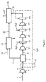
- an air flow 1 is compressed in an air compressor 3 and then separated in an air separation apparatus 7 by cryogenic distillation. If the object of the invention is simply to produce nitrogen, other methods of separation may be used.
- Nitrogen 9 is compressed in a two-stage compressor C1; C2. Between the two stages and downstream of the stage C1 is a contactor 17 with direct contact fed at the top by water. All the water is transferred to the gaseous stream of nitrogen which is then compressed in the stage C2.
- the compressed and humidified nitrogen 19 is sent to a combustion chamber 25.
- the combustion chamber 25 is also fed with a synthesis gas 23 from a gasifier 13.
- the gasifier optionally receives oxygen 11 from the air separation apparatus 7 and a fuel 15, for example natural gas, coal.
- the gas 27 produced by the combustion chamber 25 is expanded in a turbine to provide electricity.
- the nitrogen is compressed in a three-stage compressor, with a contactor between each pair of stages and downstream of the last stage.
- An air flow 1 is compressed in an air compressor 3 and then separated in an air separation apparatus 7 by cryogenic distillation. If the object of the invention is simply to produce nitrogen, other methods of separation may be used.
- Nitrogen 9 is compressed in a three-stage compressor C1, C2, C3. Between the first two stages and downstream of the first stage C1 is a direct contact contactor 17 fed at the top by water. All the water is transferred to the gaseous stream of nitrogen which is then compressed in the stage C2.
- the compressed and humidified nitrogen 19 is sent to a second contactor 117 by direct contact where it is moistened and then compressed in the stage C3.
- the compressed nitrogen in the C3 stage is optionally sent to a third contactor 217 to be humidified and then sent to a combustion chamber or turbine which expands a combustion gas produced by the combustion chamber.
- the water sent to the contactor 217 can optionally be preheated, possibly by heat exchange in a heat exchanger 6 with compressed air 1 sent to the apparatus 7, supercharged air or other hot flow. If the water used for saturation after the last stage is warmer, it will also preheat the dilution nitrogen before the combustion chamber.
- the combustion chamber 25 is also fed with a synthesis gas 23 coming from a gasifier 13.
- the gasifier optionally receives oxygen 11 from the air separation apparatus 7 and a fuel 15, for example natural gas , coal.
- the gas 27 produced by the combustion chamber 25 is expanded in a turbine to provide electricity.
- a major advantage of the invention is that it makes it possible to replace or reduce the size of at least one interstage refrigerant of the compressor because the contactor makes it possible to achieve the required cooling.
Landscapes
- Engineering & Computer Science (AREA)
- Mechanical Engineering (AREA)
- General Engineering & Computer Science (AREA)
- Physics & Mathematics (AREA)
- Thermal Sciences (AREA)
- Chemical & Material Sciences (AREA)
- Combustion & Propulsion (AREA)
- Separation By Low-Temperature Treatments (AREA)
- Engine Equipment That Uses Special Cycles (AREA)
- Air Supply (AREA)
Description
- La présente invention concerne un procédé et appareil d'alimentation en azote d'une chambre de combustion.
- Un appareil de séparation d'air est souvent utilisé pour alimenter en azote une chambre de combustion. Le carburant pour la chambre de combustion peut provenir d'une gazéification d'un combustible à l'oxygène, l'oxygène provenant également de l'appareil de séparation d'air.
- La présente invention propose une méthode pour saturer en eau et préchauffer l'azote au cours de sa compression avant introduction dans la chambre de combustion. Cette invention permet la récupération de chaleur de l'appareil de séparation d'air vers la chambre de combustion et la diminution en besoin d'azote.
- L'invention propose, en particulier, une méthode d'optimisation de l'efficacité d'une usine de production électrique par gazéification de charbon à l'oxygène et cycle combiné, ou IGCC en anglais.
- Le gaz de synthèse produit par la gazéification du charbon en présence d'oxygène est généralement épuré de ses impuretés (par exemple mercure, composés soufrés, CO2, ...) et dilué par un gaz inerte (i.e. non combustible ; par exemple azote, vapeur d'eau, CO2,...) avant ou après être mélangé à un flux d'air et être introduit (sous pression) dans une chambre de combustion de laquelle les fumées seront détendues à travers une turbine génératrice.
- Le rôle du gaz diluant est de limiter la vitesse de flamme dans la chambre de combustion, limiter le caractère oxydant du mélange gazeux et limiter les pics de température de flamme limitant ainsi la production d'oxydes d'azote à des teneurs conformes aux réglementations environnementales.
- Dans le cas d'une gazéification à l'oxygène, le gaz inerte de dilution du gaz de synthèse est classiquement l'azote coproduit par l'appareil de séparation d'air (ASU), souvent additionné de vapeur d'eau pour améliorer la capacité d'inertage du gaz de dilution en plus d'apporter une plus grande quantité de chaleur sensible à la turbine. En effet, la capacité d'inertage du gaz de dilution étant directement liée à sa capacité calorifique, l'addition de vapeur à l'azote coproduit de l'appareil permet une meilleure réduction des contraintes thermiques dans la chambre de combustion que l'utilisation d'azote seul (pour un même débit volumique de fumées vers la turbine). La vapeur est également utilisée pour préchauffer le gaz de synthèse et/ou le mélange de gaz diluant pour améliorer la productivité de la turbine génératrice.
- Bon nombre de documents décrivent une humidification de l'azote par contact direct substantiellement à la pression à laquelle l'azote doit rentrer dans la turbine à gaz, par exemple
EP-A-1001149 ,US-A-5865023 ,US2007/0119176 et « Integration of Gas Turbine and Air Separation Unit for IGCC Power Plants » de Novem, 1993. - Le rapport Novem indique en plus que l'azote est comprimé à la pression de la chambre de combustion, mélangé avec du gaz de synthèse et ensuite saturé en eau (Figure 7).
-
US-A-2011/0277860 décrit la compression d'azote sec destiné une turbine à gaz, sans humidification aucune. - La présente invention propose une méthode de préchauffage et saturation de l'azote de dilution en minimisant voire en supprimant l'utilisation de vapeur, permettant de maximiser l'utilisation de la vapeur par ailleurs (par exemple, la production d'électricité), et de limiter la portion d'azote prélevée à l'appareil de séparation d'air devant être comprimé pour constituer le gaz de dilution.
- L'azote de dilution provenant de l'appareil de séparation d'air (par exemple à une pression de 4 bar abs) doit être comprimé pour atteindre la pression de la chambre de combustion (i.e. entre 15 et 100 bar abs) ; cette compression peut être faite par un compresseur radial multi-intégré entraîné par un moteur électrique ou par une turbine à vapeur. Au cours de la compression de l'azote de dilution, l'invention propose de saturer en vapeur d'eau l'azote de dilution au moyen de contacteurs gaz-liquide alimentés par l'azote et un flux d'eau sous forme liquide.
- De préférence, à la sortie de chaque étage de compression, l'azote de dilution est saturé en vapeur d'eau par ce moyen. A l'issue de la compression, l'azote peut être réchauffé par échange de chaleur avec un fluide chauffé au contact de l'air comprimé alimentant l'appareil de séparation d'air ; le niveau de température atteint par l'azote comprimé est ici de l'ordre de 200-250°C. L'azote peut alors être à nouveau enrichi en eau, voire saturé, par un nouveau contacteur gaz-liquide. Enfin, l'azote, éventuellement saturé en eau, peut être surchauffé (réchauffeur électrique ou à la vapeur ou échange avec un autre fluide de l'ASU), classiquement de 50°C à 100°C au dessus de son point de saturation avant d'être dirigé vers la chambre de combustion.
- Par ailleurs, le flux d'eau utilisé dans les contacteurs gaz-liquide pour la saturation peut être préchauffé par un fluide de l'ASU (comme de l'air en sortie du compresseur principal d'air ou d'un surpresseur d'air) jusqu'à une température de l'ordre de 150°C afin de maximiser la quantité d'eau introduite par saturation du flux d'azote. Cette optimisation est pertinente surtout pour les injections situées en aval des étages de compression.
- En effet, les contacteurs intermédiaires, servant à saturer en eau l'azote comprimé, ont également pour rôle de refroidir le gaz avant l'étage de compression suivant et ainsi améliorant l'efficacité de la compression. Préchauffer l'eau servant à la saturation de l'azote dans les étages de compression intermédiaires réduirait donc l'efficacité de la compression.
- L'humidification entre deux étages de compression permet d'atteindre des degrés d'humidification élevés (plus de 10% d'eau dans l'azote), sans que la compression coûte trop d'énergie, grâce au refroidissement de l'azote entre deux étages. Une compression adiabatique suivie d'une humidification comme préconisé dans « Next-Generation Integration Concepts for Air Separation Units and Gas Turbines » de Smith et al, Transactions of the ASME, Vol 119, avril 1997, permet d'atteindre la même teneur en eau. Or l'énergie de compression est beaucoup plus élevée.
- Le débit d'eau alimentant les contacteurs gaz-liquide est ajusté de façon à ce qu'il n'y ait aucun condensat en sortie des contacteurs ; en effet, un débit supérieur à cette limite engendrerait des pertes thermiques, dégradant l'intérêt de l'invention.
- L'invention permet donc de produire un mélange préchauffé de gaz de dilution azote-vapeur d'eau sans prélèvement de vapeur ; la vapeur d'eau est donc avantageusement valorisée à la turbine génératrice (sauf celle éventuellement utilisée au surchauffeur), sans non plus prélèvement de chaleur sur le flux d'air sortant du turbocompresseur et alimentant la chambre de combustion.
- En résumé, cette invention peut permettre de transférer de la chaleur de l'appareil de séparation d'air vers la chambre de combustion de la turbine , de diminuer l'azote prélevé à l'appareil comme gaz de dilution et enfin de diminuer la charge massique vers la turbine alimentée par la chambre de combustion (à iso-énergie) et maintenir les contraintes mécaniques du rotor dans les limites requises. Cette invention s'applique par exemple à une unité de gazéification de charbon ou de coke de pétrole ou de résidu lourd à l'oxygène (voire à l'air), avec ou sans système de capture de CO2.
- La solution proposée a été comparée à une solution où l'azote de dilution n'est pas dilué à la vapeur. Dans cet exemple, les contacteurs ont été placés en sortie du premier et du deuxième étage de compression d'un compresseur à trois étages (pas de contacteurs en aval du dernier étage de compression).
- Pour une centrale IGCC de 450 MWe utilisant dans le cas de référence 204 000 Nm3/h d'azote de dilution, l'innovation proposée permet, à enthalpie constante, d'introduire 10 000 Nm3/h de vapeur se substituant à 13 000 Nm3/h d'azote sous pression.
- Le gain électrique résultant sur les machines de l'unité de séparation d'air est d'environ 1,2 MW soit 0,3% de la production électrique totale de la centrale IGCC.
- Comparé à une compression adiabatique avec saturation finale uniquement, (cas de l'article de Smith et al) le compresseur d'azote avec une humidification d'azote entre deux étages consomme beaucoup moins d'énergie pour une quantité d'eau similaire.
- Comparé à une compression centrifuge avec saturation finale uniquement, le compresseur d'azote avec une humidification d'azote entre deux étages permet d'introduire beaucoup plus d'eau (8% contre 2%).
- Dans une variante de l'invention, l'azote issu de l'appareil de séparation d'air peut être aussi saturé en eau dès l'entrée du compresseur, ce qui permet de produire de l'eau glacée et permettre de réduire la consommation énergétique du groupe frigorifique en amont de l'unité de purification d'air par adsorption.
- Selon un objet de l'invention, il est prévu un procédé d'alimentation en azote d'une chambre de combustion dans lequel : de l'azote gazeux est soutiré d'un appareil de séparation d'air à une première pression, l'azote est comprimé dans un compresseur d'azote et envoyé à une chambre de combustion à une deuxième pression, qui est la pression de sortie du dernier étage du compresseur d'azote caractérisé en ce que le compresseur d'azote comprend au moins deux étages et entre deux étages du compresseur d'azote, l'azote est humidifié par contact direct en passant dans un contacteur alimenté en tête par de l'eau et l'azote humidifié est comprimé dans au moins un étage du compresseur d'azote
- Selon un objet de l'invention, il est prévu un procédé d'alimentation en azote d'une chambre de combustion dans lequel : de l'azote gazeux est soutiré d'un appareil de séparation d'air à une première pression, l'azote est comprimé dans au moins deux étages d'un compresseur d'azote et envoyé à une chambre de combustion à une deuxième pression, qui est la pression de sortie du dernier étage du compresseur d'azote caractérisé en ce qu'entre deux étages du compresseur d'azote, l'azote est humidifié par contact direct en passant dans un contacteur alimenté en tête par de l'eau et l'azote humidifié est comprimé dans au moins un étage du compresseur d'azote et envoyé à la chambre de combustion.
- Selon d'autres aspects facultatifs :
- toute l'eau envoyée au contacteur est transférée au flux gazeux d'azote.
- l'eau envoyée au contacteur est à une température qui diffère au plus de 10°C, voire de 5°C, de la température ambiante.
- l'eau envoyée au contacteur est à la température ambiante.
- l'azote est également humidifié dans un contacteur en aval du dernier étage du compresseur d'azote.
- l'eau envoyée dans le contacteur en aval du dernier étage du compresseur d'azote est préchauffée par un flux de l'unité de séparation d'air.
- l'azote est humidifié uniquement par contact direct avec de l'eau.
- un gaz de la chambre de combustion est détendu dans une turbine.
- la chambre de combustion est alimentée par un carburant provenant d'une unité de gazéification, l'unité de gazéification étant alimenté par de l'oxygène gazeux provenant de l'appareil de séparation d'air.
- seule une partie de l'eau envoyée au contacteur est transférée au flux gazeux d'azote et l'eau excédentaire sortant du contacteur sous forme liquide est utilisée comme eau glacée dans l'unité de séparation d'air.
- Selon un autre objet de l'invention, il est prévu un appareil d'alimentation en azote d'une chambre de combustion comprenant un compresseur, au moins un contacteur à contact direct disposé pour recevoir de l'azote comprimé provenant d'un étage du compresseur ainsi que des moyens pour envoyer de l'eau à l'au moins un contacteur, au moins une conduite pour envoyer de l'azote comprimé du dernier étage du compresseur à la chambre de combustion caractérisé en ce que le compresseur ayant au moins deux étages, en ce que le contacteur est relié en aval d'un étage du compresseur et en amont d'un autre étage du compresseur pour recevoir de l'azote comprimé et pour envoyer de l'azote humidifié à l'étage suivant, des moyens pour envoyer de l'azote comprimé et humidifié du dernier étage du compresseur à la chambre de combustion à travers l'au moins une conduite.
- L'appareil peut comprendre des moyens pour humidifier l'azote par contact direct en aval du dernier étage du compresseur ou pas.
- Le contacteur constitue de préférence un moyen de refroidissement de l'azote comprimé.
- Le contacteur peut ne pas comprendre de moyen de sortie de liquide.
- Selon un autre objet de l'invention, il est prévu un appareil de séparation d'air intégré avec une turbine à gaz comprenant un appareil de séparation d'air, un appareil de compression d'azote provenant de l'appareil de séparation d'air, comprenant un compresseur ayant au moins deux étages, au moins un contacteur à contact direct disposé pour recevoir de l'azote comprimé dans un étage du compresseur et pour envoyer de l'azote comprimé et humidifié au prochain étage du compresseur ainsi que des moyens pour envoyer de l'eau à l'au moins un contacteur, une chambre de combustion, une turbine, des moyens pour envoyer un gaz de combustion de la chambre de combustion à la turbine et des moyens pour envoyer de l'azote comprimé et humidifié du dernier étage du compresseur à la chambre de combustion et/ou à la turbine.
- L'invention sera décrite en plus de détail en se référant aux figures.
- Dans la
Figure 1 , un débit d'air 1 est comprimé dans un compresseur d'air 3 et puis séparé dans un appareil de séparation d'air 7 par distillation cryogénique. Si le but de l'invention est simplement de produire de l'azote, d'autres méthodes de séparation peuvent être utilisées. L'azote 9 est comprimé dans un compresseur à deux étages C1; C2. Entre les deux étages et en aval de l'étage C1 se trouve un contacteur 17 à contact direct alimenté en tête par de l'eau. Toute l'eau est transférée au flux gazeux d'azote qui est ensuite comprimé dans l'étage C2. L'azote comprimé et humidifié 19 est envoyé à une chambre de combustion 25. La chambre de combustion 25 est également alimentée par un gaz de synthèse 23 provenant d'un gazéifieur 13. Le gazéifieur reçoit éventuellement de l'oxygène 11 de l'appareil de séparation d'air 7 et un carburant 15, par exemple du gaz naturel, du charbon. - Le gaz 27 produit par la chambre de combustion 25 est détendu dans une turbine pour fournir de l'électricité.
- Dans la
Figure 2 , l'azote est comprimé dans un compresseur à trois étages, avec un contacteur entre chaque paire d'étages et en aval du dernier étage. Un débit d'air 1 est comprimé dans un compresseur d'air 3 et puis séparé dans un appareil de séparation d'air 7 par distillation cryogénique. Si le but de l'invention est simplement de produire de l'azote, d'autres méthodes de séparation peuvent être utilisées. L'azote 9 est comprimé dans un compresseur à trois étages C1, C2, C3. Entre les deux premiers étages et en aval du premier étage C1 se trouve un contacteur 17 à contact direct alimenté en tête par de l'eau. Toute l'eau est transférée au flux gazeux d'azote qui est ensuite comprimé dans l'étage C2. L'azote comprimé et humidifié 19 est envoyé à un deuxième contacteur 117 par contact direct où il est humidifié et ensuite comprimé dans l'étage C3. L'azote comprimé dans l'étage C3 est éventuellement envoyé à un troisième contacteur 217 pour être humidifié et est ensuite envoyé à une chambre de combustion 25 ou à une turbine qui détend un gaz de combustion produit par la chambre de combustion. L'eau envoyée au contacteur 217 peut éventuellement être préchauffée, éventuellement par échange de chaleur dans un échangeur 6 avec de l'air comprimé 1 envoyé à l'appareil 7, de l'air surpressé ou un autre débit chaud. Si l'eau servant à la saturation après dernier étage est plus chaude, elle va aussi préchauffer l'azote de dilution avant la chambre de combustion. La chambre de combustion 25 est également alimentée par un gaz de synthèse 23 provenant d'un gazéifieur 13. Le gazéifieur reçoit éventuellement de l'oxygène 11 de l'appareil de séparation d'air 7 et un carburant 15, par exemple du gaz naturel, du charbon. - Le gaz 27 produit par la chambre de combustion 25 est détendu dans une turbine pour fournir de l'électricité.
- Un avantage majeur de l'invention est qu'il permet de remplacer ou de réduire la taille d'au moins un réfrigérant inter-étage du compresseur car le contacteur permet de réaliser le refroidissement requis.
Claims (15)
- Procédé d'alimentation en azote d'une chambre de combustion dans lequel : de l'azote gazeux (9) est soutiré d'un appareil de séparation d'air (7) à une première pression, l'azote est comprimé dans un compresseur d'azote (C1, C2, C3) et envoyé à une chambre de combustion (25) à une deuxième pression, qui est la pression de sortie du dernier étage (C3) du compresseur d'azote caractérisé en ce que le compresseur d'azote comprend au moins deux étages et entre deux étages du compresseur d'azote, l'azote est humidifié par contact direct en passant dans un contacteur (17, 117) alimenté en tête par de l'eau et l'azote humidifié est comprimé dans au moins un étage du compresseur d'azote pour former l'azote à la deuxième pression envoyé à la chambre de combustion.
- Procédé selon la revendication 1 dans lequel toute l'eau envoyée au contacteur est transférée au flux gazeux d'azote.
- Procédé selon la revendication 1 ou 2 dans lequel l'eau envoyée au contacteur (17, 117) est à une température qui diffère au plus de 10°C, voire de 5°C, de la température ambiante.
- Procédé selon l'une des revendications précédentes dans lequel l'azote est également humidifié dans un contacteur (217) en aval du dernier étage du compresseur d'azote.
- Procédé selon la revendication 4 dans lequel l'eau envoyée dans le contacteur (217) en aval du dernier étage du compresseur d'azote est préchauffée par un flux (1) de l'unité de séparation d'air.
- Procédé selon l'une des revendications précédentes dans lequel l'azote (9) est humidifié uniquement par contact direct avec de l'eau.
- Procédé selon l'une des revendications précédentes dans lequel un gaz de la chambre de combustion (25) est détendu dans une turbine.
- Procédé selon l'une des revendications précédentes dans lequel la chambre de combustion (25) est alimentée par un carburant (23) provenant d'une unité de gazéification, l'unité de gazéification étant alimenté par de l'oxygène gazeux (11) provenant de l'appareil de séparation d'air (7).
- Procédé selon l'une des revendications précédentes dans lequel seule une partie de l'eau envoyée au contacteur (17, 117, 217) est transférée au flux gazeux d'azote et l'eau excédentaire sortant du contacteur sous forme liquide est utilisée comme eau glacée dans l'unité de séparation d'air.
- Procédé selon l'une des revendications précédentes dans lequel l'azote est refroidi par contact direct avec l'eau dans le contacteur (17, 117).
- Appareil d'alimentation en azote d'une chambre de combustion comprenant un compresseur (C1, C2, C3), au moins un contacteur (17, 117) à contact direct disposé pour recevoir de l'azote comprimé provenant d'un étage du compresseur ainsi que des moyens pour envoyer de l'eau à l'au moins un contacteur, au moins une conduite pour envoyer de l'azote comprimé du dernier étage du compresseur à la chambre de combustion caractérisé en ce que le compresseur ayant au moins deux étages, en ce que le contacteur est relié en aval d'un étage du compresseur et en amont d'un autre étage du compresseur pour recevoir de l'azote comprimé et pour envoyer de l'azote humidifié à l'étage suivant, des moyens pour envoyer de l'azote comprimé et humidifié du dernier étage du compresseur à la chambre de combustion à travers l'au moins une conduite.
- Appareil selon la revendication 11 comprenant des moyens (217) pour humidifier l'azote par contact direct en aval du dernier étage du compresseur.
- Appareil selon la revendication 11 sans moyen d'humidification de l'azote en aval du dernier étage du compresseur.
- Appareil selon l'une des revendications 11 à 13 dans lequel le contacteur (17, 117, 217) constitue un moyen de refroidissement de l'azote comprimé.
- Appareil selon l'une des revendications 11 à 14 dans lequel le contacteur (17, 117, 217) ne comprend pas de moyen de sortie de liquide.
Priority Applications (1)
| Application Number | Priority Date | Filing Date | Title |
|---|---|---|---|
| PL12806566T PL2783091T3 (pl) | 2011-11-25 | 2012-11-23 | Sposób i urządzenie do zasilania komory spalania azotem |
Applications Claiming Priority (2)
| Application Number | Priority Date | Filing Date | Title |
|---|---|---|---|
| FR1160792A FR2983245B1 (fr) | 2011-11-25 | 2011-11-25 | Procede et appareil d'alimentation en azote d'une chambre de combustion |
| PCT/FR2012/052716 WO2013076435A1 (fr) | 2011-11-25 | 2012-11-23 | Procédé et appareil d'alimentation en azote d'une chambre de combustion |
Publications (2)
| Publication Number | Publication Date |
|---|---|
| EP2783091A1 EP2783091A1 (fr) | 2014-10-01 |
| EP2783091B1 true EP2783091B1 (fr) | 2016-02-03 |
Family
ID=47436063
Family Applications (1)
| Application Number | Title | Priority Date | Filing Date |
|---|---|---|---|
| EP12806566.1A Not-in-force EP2783091B1 (fr) | 2011-11-25 | 2012-11-23 | Procédé et appareil d'alimentation en azote d'une chambre de combustion |
Country Status (7)
| Country | Link |
|---|---|
| US (1) | US9644533B2 (fr) |
| EP (1) | EP2783091B1 (fr) |
| JP (1) | JP2015500934A (fr) |
| CN (1) | CN103958853B (fr) |
| FR (1) | FR2983245B1 (fr) |
| PL (1) | PL2783091T3 (fr) |
| WO (1) | WO2013076435A1 (fr) |
Families Citing this family (2)
| Publication number | Priority date | Publication date | Assignee | Title |
|---|---|---|---|---|
| WO2018042336A2 (fr) * | 2016-08-30 | 2018-03-08 | 8 Rivers Capital, Llc | Procédé de séparation d'air cryogénique pour produire de l'oxygène à des pressions élevées |
| CN117927873B (zh) * | 2024-03-25 | 2024-06-21 | 玉得气体有限责任公司 | 用于平衡管路中氮气的气量控制方法及系统 |
Family Cites Families (15)
| Publication number | Priority date | Publication date | Assignee | Title |
|---|---|---|---|---|
| US5241816A (en) * | 1991-12-09 | 1993-09-07 | Praxair Technology, Inc. | Gas turbine steam addition |
| US5251433A (en) * | 1992-12-24 | 1993-10-12 | Texaco Inc. | Power generation process |
| US5388395A (en) * | 1993-04-27 | 1995-02-14 | Air Products And Chemicals, Inc. | Use of nitrogen from an air separation unit as gas turbine air compressor feed refrigerant to improve power output |
| US5666800A (en) * | 1994-06-14 | 1997-09-16 | Air Products And Chemicals, Inc. | Gasification combined cycle power generation process with heat-integrated chemical production |
| US5901547A (en) * | 1996-06-03 | 1999-05-11 | Air Products And Chemicals, Inc. | Operation method for integrated gasification combined cycle power generation system |
| US5802875A (en) * | 1997-05-28 | 1998-09-08 | Praxair Technology, Inc. | Method and apparatus for control of an integrated croyogenic air separation unit/gas turbine system |
| US6343462B1 (en) * | 1998-11-13 | 2002-02-05 | Praxair Technology, Inc. | Gas turbine power augmentation by the addition of nitrogen and moisture to the fuel gas |
| US6508053B1 (en) * | 1999-04-09 | 2003-01-21 | L'air Liquide-Societe Anonyme A'directoire Et Conseil De Surveillance Pour L'etude Et L'exploitation Des Procedes Georges Claude | Integrated power generation system |
| US6295838B1 (en) * | 2000-08-16 | 2001-10-02 | Praxair Technology, Inc. | Cryogenic air separation and gas turbine integration using heated nitrogen |
| US7137257B2 (en) * | 2004-10-06 | 2006-11-21 | Praxair Technology, Inc. | Gas turbine power augmentation method |
| CA2566167C (fr) * | 2005-11-08 | 2010-11-16 | Bj Services Company | Methode et dispositif permettant de rechauffer davantage un appareil |
| JP4311415B2 (ja) * | 2006-06-26 | 2009-08-12 | 株式会社日立製作所 | 冷却装置,冷却装置を用いたガスタービンシステム,冷却機構を用いたヒートポンプシステム,冷却方法,冷却装置の運転方法 |
| US20100199558A1 (en) * | 2009-02-10 | 2010-08-12 | Steele Raymond Douglas | System and method for operating power generation systems |
| JP5412205B2 (ja) * | 2009-07-31 | 2014-02-12 | 三菱重工業株式会社 | ガスタービンプラント及びこれを備えたガス化燃料発電設備 |
| US8303695B2 (en) * | 2010-05-17 | 2012-11-06 | General Electric Company | Systems for compressing a gas |
-
2011
- 2011-11-25 FR FR1160792A patent/FR2983245B1/fr not_active Expired - Fee Related
-
2012
- 2012-11-23 US US14/359,155 patent/US9644533B2/en not_active Expired - Fee Related
- 2012-11-23 EP EP12806566.1A patent/EP2783091B1/fr not_active Not-in-force
- 2012-11-23 WO PCT/FR2012/052716 patent/WO2013076435A1/fr not_active Ceased
- 2012-11-23 JP JP2014542921A patent/JP2015500934A/ja active Pending
- 2012-11-23 PL PL12806566T patent/PL2783091T3/pl unknown
- 2012-11-23 CN CN201280058038.3A patent/CN103958853B/zh not_active Expired - Fee Related
Also Published As
| Publication number | Publication date |
|---|---|
| EP2783091A1 (fr) | 2014-10-01 |
| FR2983245A1 (fr) | 2013-05-31 |
| FR2983245B1 (fr) | 2014-01-10 |
| US9644533B2 (en) | 2017-05-09 |
| US20140360201A1 (en) | 2014-12-11 |
| PL2783091T3 (pl) | 2016-06-30 |
| CN103958853A (zh) | 2014-07-30 |
| WO2013076435A1 (fr) | 2013-05-30 |
| JP2015500934A (ja) | 2015-01-08 |
| CN103958853B (zh) | 2017-05-31 |
Similar Documents
| Publication | Publication Date | Title |
|---|---|---|
| JP2013535604A (ja) | 低エミッショントリプルサイクル発電システム及び方法 | |
| AU2016201209B2 (en) | High pressure fossil fuel oxy-combustion system with carbon dioxide capture for interface with an energy conversion system | |
| FR2928845A1 (fr) | Systeme de capture et recuperation de dioxyde de carbone, et procede de recuperation de dioxyde de carbone dans un tel systeme. | |
| US9273607B2 (en) | Generating power using an ion transport membrane | |
| EA029301B1 (ru) | Интегрированные системы для получения со(варианты) и способ производства электроэнергии | |
| CN103459956A (zh) | 用于控制空气分离单元的系统和方法 | |
| EP2783091A1 (fr) | Procédé et appareil d'alimentation en azote d'une chambre de combustion | |
| US8850825B2 (en) | Generating power using an ion transport membrane | |
| WO2014096613A1 (fr) | Recuperation energetique des fumees d'un four de fusion au moyen d'une turbine a gaz et des échangeurs de chaleur | |
| US20180334957A1 (en) | Method and apparatus for operating a gas turbine using wet combustion | |
| US8414667B2 (en) | Supercritical pressurization of fuel slurry | |
| JP6301118B2 (ja) | ガス化燃料電池複合発電システム及びガス化燃料電池複合発電システムの運転方法 | |
| RU2277638C1 (ru) | Способ и устройство для получения электроэнергии путем использования конденсированных топлив | |
| WO2014160104A9 (fr) | Procédé et appareil pour générer de l'oxygène et un diluant | |
| US20140196370A1 (en) | Co-Fired Syngas System | |
| WO2014059524A1 (fr) | Systèmes et procédés pour la combustion de soufre avec une chambre de combustion multi-étage | |
| JP2010184844A (ja) | 酸素製造プラントの運転方式 | |
| HK1193864B (en) | High pressure fossil fuel oxy-combustion system with carbon dioxide capture for interface with an energy conversion system |
Legal Events
| Date | Code | Title | Description |
|---|---|---|---|
| PUAI | Public reference made under article 153(3) epc to a published international application that has entered the european phase |
Free format text: ORIGINAL CODE: 0009012 |
|
| 17P | Request for examination filed |
Effective date: 20140625 |
|
| AK | Designated contracting states |
Kind code of ref document: A1 Designated state(s): AL AT BE BG CH CY CZ DE DK EE ES FI FR GB GR HR HU IE IS IT LI LT LU LV MC MK MT NL NO PL PT RO RS SE SI SK SM TR |
|
| DAX | Request for extension of the european patent (deleted) | ||
| GRAP | Despatch of communication of intention to grant a patent |
Free format text: ORIGINAL CODE: EPIDOSNIGR1 |
|
| INTG | Intention to grant announced |
Effective date: 20150811 |
|
| GRAS | Grant fee paid |
Free format text: ORIGINAL CODE: EPIDOSNIGR3 |
|
| GRAA | (expected) grant |
Free format text: ORIGINAL CODE: 0009210 |
|
| AK | Designated contracting states |
Kind code of ref document: B1 Designated state(s): AL AT BE BG CH CY CZ DE DK EE ES FI FR GB GR HR HU IE IS IT LI LT LU LV MC MK MT NL NO PL PT RO RS SE SI SK SM TR |
|
| REG | Reference to a national code |
Ref country code: GB Ref legal event code: FG4D Free format text: NOT ENGLISH |
|
| REG | Reference to a national code |
Ref country code: AT Ref legal event code: REF Ref document number: 773824 Country of ref document: AT Kind code of ref document: T Effective date: 20160215 Ref country code: CH Ref legal event code: EP |
|
| REG | Reference to a national code |
Ref country code: IE Ref legal event code: FG4D Free format text: LANGUAGE OF EP DOCUMENT: FRENCH |
|
| REG | Reference to a national code |
Ref country code: DE Ref legal event code: R096 Ref document number: 602012014542 Country of ref document: DE |
|
| REG | Reference to a national code |
Ref country code: LT Ref legal event code: MG4D Ref country code: NL Ref legal event code: MP Effective date: 20160203 |
|
| REG | Reference to a national code |
Ref country code: AT Ref legal event code: MK05 Ref document number: 773824 Country of ref document: AT Kind code of ref document: T Effective date: 20160203 |
|
| PG25 | Lapsed in a contracting state [announced via postgrant information from national office to epo] |
Ref country code: FI Free format text: LAPSE BECAUSE OF FAILURE TO SUBMIT A TRANSLATION OF THE DESCRIPTION OR TO PAY THE FEE WITHIN THE PRESCRIBED TIME-LIMIT Effective date: 20160203 Ref country code: GR Free format text: LAPSE BECAUSE OF FAILURE TO SUBMIT A TRANSLATION OF THE DESCRIPTION OR TO PAY THE FEE WITHIN THE PRESCRIBED TIME-LIMIT Effective date: 20160504 Ref country code: ES Free format text: LAPSE BECAUSE OF FAILURE TO SUBMIT A TRANSLATION OF THE DESCRIPTION OR TO PAY THE FEE WITHIN THE PRESCRIBED TIME-LIMIT Effective date: 20160203 Ref country code: HR Free format text: LAPSE BECAUSE OF FAILURE TO SUBMIT A TRANSLATION OF THE DESCRIPTION OR TO PAY THE FEE WITHIN THE PRESCRIBED TIME-LIMIT Effective date: 20160203 Ref country code: NO Free format text: LAPSE BECAUSE OF FAILURE TO SUBMIT A TRANSLATION OF THE DESCRIPTION OR TO PAY THE FEE WITHIN THE PRESCRIBED TIME-LIMIT Effective date: 20160503 |
|
| PG25 | Lapsed in a contracting state [announced via postgrant information from national office to epo] |
Ref country code: NL Free format text: LAPSE BECAUSE OF FAILURE TO SUBMIT A TRANSLATION OF THE DESCRIPTION OR TO PAY THE FEE WITHIN THE PRESCRIBED TIME-LIMIT Effective date: 20160203 Ref country code: PT Free format text: LAPSE BECAUSE OF FAILURE TO SUBMIT A TRANSLATION OF THE DESCRIPTION OR TO PAY THE FEE WITHIN THE PRESCRIBED TIME-LIMIT Effective date: 20160603 Ref country code: SE Free format text: LAPSE BECAUSE OF FAILURE TO SUBMIT A TRANSLATION OF THE DESCRIPTION OR TO PAY THE FEE WITHIN THE PRESCRIBED TIME-LIMIT Effective date: 20160203 Ref country code: LV Free format text: LAPSE BECAUSE OF FAILURE TO SUBMIT A TRANSLATION OF THE DESCRIPTION OR TO PAY THE FEE WITHIN THE PRESCRIBED TIME-LIMIT Effective date: 20160203 Ref country code: RS Free format text: LAPSE BECAUSE OF FAILURE TO SUBMIT A TRANSLATION OF THE DESCRIPTION OR TO PAY THE FEE WITHIN THE PRESCRIBED TIME-LIMIT Effective date: 20160203 Ref country code: AT Free format text: LAPSE BECAUSE OF FAILURE TO SUBMIT A TRANSLATION OF THE DESCRIPTION OR TO PAY THE FEE WITHIN THE PRESCRIBED TIME-LIMIT Effective date: 20160203 Ref country code: IS Free format text: LAPSE BECAUSE OF FAILURE TO SUBMIT A TRANSLATION OF THE DESCRIPTION OR TO PAY THE FEE WITHIN THE PRESCRIBED TIME-LIMIT Effective date: 20160603 Ref country code: LT Free format text: LAPSE BECAUSE OF FAILURE TO SUBMIT A TRANSLATION OF THE DESCRIPTION OR TO PAY THE FEE WITHIN THE PRESCRIBED TIME-LIMIT Effective date: 20160203 |
|
| PG25 | Lapsed in a contracting state [announced via postgrant information from national office to epo] |
Ref country code: DK Free format text: LAPSE BECAUSE OF FAILURE TO SUBMIT A TRANSLATION OF THE DESCRIPTION OR TO PAY THE FEE WITHIN THE PRESCRIBED TIME-LIMIT Effective date: 20160203 Ref country code: EE Free format text: LAPSE BECAUSE OF FAILURE TO SUBMIT A TRANSLATION OF THE DESCRIPTION OR TO PAY THE FEE WITHIN THE PRESCRIBED TIME-LIMIT Effective date: 20160203 |
|
| REG | Reference to a national code |
Ref country code: DE Ref legal event code: R097 Ref document number: 602012014542 Country of ref document: DE |
|
| PG25 | Lapsed in a contracting state [announced via postgrant information from national office to epo] |
Ref country code: CZ Free format text: LAPSE BECAUSE OF FAILURE TO SUBMIT A TRANSLATION OF THE DESCRIPTION OR TO PAY THE FEE WITHIN THE PRESCRIBED TIME-LIMIT Effective date: 20160203 Ref country code: RO Free format text: LAPSE BECAUSE OF FAILURE TO SUBMIT A TRANSLATION OF THE DESCRIPTION OR TO PAY THE FEE WITHIN THE PRESCRIBED TIME-LIMIT Effective date: 20160203 Ref country code: SM Free format text: LAPSE BECAUSE OF FAILURE TO SUBMIT A TRANSLATION OF THE DESCRIPTION OR TO PAY THE FEE WITHIN THE PRESCRIBED TIME-LIMIT Effective date: 20160203 Ref country code: SK Free format text: LAPSE BECAUSE OF FAILURE TO SUBMIT A TRANSLATION OF THE DESCRIPTION OR TO PAY THE FEE WITHIN THE PRESCRIBED TIME-LIMIT Effective date: 20160203 |
|
| PLBE | No opposition filed within time limit |
Free format text: ORIGINAL CODE: 0009261 |
|
| STAA | Information on the status of an ep patent application or granted ep patent |
Free format text: STATUS: NO OPPOSITION FILED WITHIN TIME LIMIT |
|
| 26N | No opposition filed |
Effective date: 20161104 |
|
| PGFP | Annual fee paid to national office [announced via postgrant information from national office to epo] |
Ref country code: DE Payment date: 20161121 Year of fee payment: 5 Ref country code: GB Payment date: 20161122 Year of fee payment: 5 |
|
| PG25 | Lapsed in a contracting state [announced via postgrant information from national office to epo] |
Ref country code: BG Free format text: LAPSE BECAUSE OF FAILURE TO SUBMIT A TRANSLATION OF THE DESCRIPTION OR TO PAY THE FEE WITHIN THE PRESCRIBED TIME-LIMIT Effective date: 20160503 Ref country code: BE Free format text: LAPSE BECAUSE OF NON-PAYMENT OF DUE FEES Effective date: 20161130 Ref country code: SI Free format text: LAPSE BECAUSE OF FAILURE TO SUBMIT A TRANSLATION OF THE DESCRIPTION OR TO PAY THE FEE WITHIN THE PRESCRIBED TIME-LIMIT Effective date: 20160203 |
|
| PGFP | Annual fee paid to national office [announced via postgrant information from national office to epo] |
Ref country code: PL Payment date: 20161026 Year of fee payment: 5 Ref country code: IT Payment date: 20161124 Year of fee payment: 5 |
|
| REG | Reference to a national code |
Ref country code: CH Ref legal event code: PL |
|
| PG25 | Lapsed in a contracting state [announced via postgrant information from national office to epo] |
Ref country code: LI Free format text: LAPSE BECAUSE OF NON-PAYMENT OF DUE FEES Effective date: 20161130 Ref country code: CH Free format text: LAPSE BECAUSE OF NON-PAYMENT OF DUE FEES Effective date: 20161130 |
|
| REG | Reference to a national code |
Ref country code: IE Ref legal event code: MM4A |
|
| REG | Reference to a national code |
Ref country code: FR Ref legal event code: ST Effective date: 20170731 |
|
| PG25 | Lapsed in a contracting state [announced via postgrant information from national office to epo] |
Ref country code: LU Free format text: LAPSE BECAUSE OF NON-PAYMENT OF DUE FEES Effective date: 20161130 |
|
| PG25 | Lapsed in a contracting state [announced via postgrant information from national office to epo] |
Ref country code: FR Free format text: LAPSE BECAUSE OF NON-PAYMENT OF DUE FEES Effective date: 20161130 |
|
| PG25 | Lapsed in a contracting state [announced via postgrant information from national office to epo] |
Ref country code: IE Free format text: LAPSE BECAUSE OF NON-PAYMENT OF DUE FEES Effective date: 20161123 |
|
| REG | Reference to a national code |
Ref country code: BE Ref legal event code: MM Effective date: 20161130 |
|
| PG25 | Lapsed in a contracting state [announced via postgrant information from national office to epo] |
Ref country code: HU Free format text: LAPSE BECAUSE OF FAILURE TO SUBMIT A TRANSLATION OF THE DESCRIPTION OR TO PAY THE FEE WITHIN THE PRESCRIBED TIME-LIMIT; INVALID AB INITIO Effective date: 20121123 |
|
| REG | Reference to a national code |
Ref country code: DE Ref legal event code: R119 Ref document number: 602012014542 Country of ref document: DE |
|
| PG25 | Lapsed in a contracting state [announced via postgrant information from national office to epo] |
Ref country code: MK Free format text: LAPSE BECAUSE OF FAILURE TO SUBMIT A TRANSLATION OF THE DESCRIPTION OR TO PAY THE FEE WITHIN THE PRESCRIBED TIME-LIMIT Effective date: 20160203 Ref country code: CY Free format text: LAPSE BECAUSE OF FAILURE TO SUBMIT A TRANSLATION OF THE DESCRIPTION OR TO PAY THE FEE WITHIN THE PRESCRIBED TIME-LIMIT Effective date: 20160203 Ref country code: MC Free format text: LAPSE BECAUSE OF FAILURE TO SUBMIT A TRANSLATION OF THE DESCRIPTION OR TO PAY THE FEE WITHIN THE PRESCRIBED TIME-LIMIT Effective date: 20160203 |
|
| GBPC | Gb: european patent ceased through non-payment of renewal fee |
Effective date: 20171123 |
|
| PG25 | Lapsed in a contracting state [announced via postgrant information from national office to epo] |
Ref country code: MT Free format text: LAPSE BECAUSE OF FAILURE TO SUBMIT A TRANSLATION OF THE DESCRIPTION OR TO PAY THE FEE WITHIN THE PRESCRIBED TIME-LIMIT Effective date: 20160203 |
|
| PG25 | Lapsed in a contracting state [announced via postgrant information from national office to epo] |
Ref country code: IT Free format text: LAPSE BECAUSE OF NON-PAYMENT OF DUE FEES Effective date: 20171123 Ref country code: TR Free format text: LAPSE BECAUSE OF FAILURE TO SUBMIT A TRANSLATION OF THE DESCRIPTION OR TO PAY THE FEE WITHIN THE PRESCRIBED TIME-LIMIT Effective date: 20160203 Ref country code: DE Free format text: LAPSE BECAUSE OF NON-PAYMENT OF DUE FEES Effective date: 20180602 Ref country code: AL Free format text: LAPSE BECAUSE OF FAILURE TO SUBMIT A TRANSLATION OF THE DESCRIPTION OR TO PAY THE FEE WITHIN THE PRESCRIBED TIME-LIMIT Effective date: 20160203 |
|
| PG25 | Lapsed in a contracting state [announced via postgrant information from national office to epo] |
Ref country code: GB Free format text: LAPSE BECAUSE OF NON-PAYMENT OF DUE FEES Effective date: 20171123 |
|
| PG25 | Lapsed in a contracting state [announced via postgrant information from national office to epo] |
Ref country code: PL Free format text: LAPSE BECAUSE OF NON-PAYMENT OF DUE FEES Effective date: 20171123 |