EP2782216A2 - Magnet-embedded rotor, method for manufacturing the same, and magnetization device - Google Patents
Magnet-embedded rotor, method for manufacturing the same, and magnetization device Download PDFInfo
- Publication number
- EP2782216A2 EP2782216A2 EP14160845.5A EP14160845A EP2782216A2 EP 2782216 A2 EP2782216 A2 EP 2782216A2 EP 14160845 A EP14160845 A EP 14160845A EP 2782216 A2 EP2782216 A2 EP 2782216A2
- Authority
- EP
- European Patent Office
- Prior art keywords
- magnet
- core
- rotor
- embedded
- magnetization
- Prior art date
- Legal status (The legal status is an assumption and is not a legal conclusion. Google has not performed a legal analysis and makes no representation as to the accuracy of the status listed.)
- Granted
Links
- 230000005415 magnetization Effects 0.000 title claims description 112
- 238000000034 method Methods 0.000 title claims description 36
- 238000004519 manufacturing process Methods 0.000 title claims description 30
- 230000002093 peripheral effect Effects 0.000 claims description 55
- 239000000463 material Substances 0.000 claims description 52
- 230000004907 flux Effects 0.000 claims description 33
- 230000008569 process Effects 0.000 claims description 15
- 238000003780 insertion Methods 0.000 description 18
- 230000037431 insertion Effects 0.000 description 18
- 230000004048 modification Effects 0.000 description 14
- 238000012986 modification Methods 0.000 description 14
- 230000000694 effects Effects 0.000 description 9
- 229910000831 Steel Inorganic materials 0.000 description 7
- 239000010959 steel Substances 0.000 description 7
- 230000003247 decreasing effect Effects 0.000 description 6
- 230000007423 decrease Effects 0.000 description 3
- 238000001746 injection moulding Methods 0.000 description 3
- XEEYBQQBJWHFJM-UHFFFAOYSA-N Iron Chemical compound [Fe] XEEYBQQBJWHFJM-UHFFFAOYSA-N 0.000 description 2
- 230000009467 reduction Effects 0.000 description 2
- 238000000748 compression moulding Methods 0.000 description 1
- 238000002347 injection Methods 0.000 description 1
- 239000007924 injection Substances 0.000 description 1
- 229910052742 iron Inorganic materials 0.000 description 1
- 239000000696 magnetic material Substances 0.000 description 1
- 229920006395 saturated elastomer Polymers 0.000 description 1
Images





Classifications
-
- H—ELECTRICITY
- H02—GENERATION; CONVERSION OR DISTRIBUTION OF ELECTRIC POWER
- H02K—DYNAMO-ELECTRIC MACHINES
- H02K1/00—Details of the magnetic circuit
- H02K1/06—Details of the magnetic circuit characterised by the shape, form or construction
- H02K1/22—Rotating parts of the magnetic circuit
- H02K1/27—Rotor cores with permanent magnets
-
- H—ELECTRICITY
- H02—GENERATION; CONVERSION OR DISTRIBUTION OF ELECTRIC POWER
- H02K—DYNAMO-ELECTRIC MACHINES
- H02K1/00—Details of the magnetic circuit
- H02K1/06—Details of the magnetic circuit characterised by the shape, form or construction
- H02K1/22—Rotating parts of the magnetic circuit
- H02K1/27—Rotor cores with permanent magnets
- H02K1/2706—Inner rotors
- H02K1/272—Inner rotors the magnetisation axis of the magnets being perpendicular to the rotor axis
- H02K1/274—Inner rotors the magnetisation axis of the magnets being perpendicular to the rotor axis the rotor consisting of two or more circumferentially positioned magnets
- H02K1/2753—Inner rotors the magnetisation axis of the magnets being perpendicular to the rotor axis the rotor consisting of two or more circumferentially positioned magnets the rotor consisting of magnets or groups of magnets arranged with alternating polarity
- H02K1/276—Magnets embedded in the magnetic core, e.g. interior permanent magnets [IPM]
-
- H—ELECTRICITY
- H02—GENERATION; CONVERSION OR DISTRIBUTION OF ELECTRIC POWER
- H02K—DYNAMO-ELECTRIC MACHINES
- H02K1/00—Details of the magnetic circuit
- H02K1/06—Details of the magnetic circuit characterised by the shape, form or construction
- H02K1/22—Rotating parts of the magnetic circuit
- H02K1/27—Rotor cores with permanent magnets
- H02K1/2706—Inner rotors
- H02K1/272—Inner rotors the magnetisation axis of the magnets being perpendicular to the rotor axis
- H02K1/274—Inner rotors the magnetisation axis of the magnets being perpendicular to the rotor axis the rotor consisting of two or more circumferentially positioned magnets
- H02K1/2753—Inner rotors the magnetisation axis of the magnets being perpendicular to the rotor axis the rotor consisting of two or more circumferentially positioned magnets the rotor consisting of magnets or groups of magnets arranged with alternating polarity
- H02K1/276—Magnets embedded in the magnetic core, e.g. interior permanent magnets [IPM]
- H02K1/2766—Magnets embedded in the magnetic core, e.g. interior permanent magnets [IPM] having a flux concentration effect
-
- H—ELECTRICITY
- H02—GENERATION; CONVERSION OR DISTRIBUTION OF ELECTRIC POWER
- H02K—DYNAMO-ELECTRIC MACHINES
- H02K1/00—Details of the magnetic circuit
- H02K1/06—Details of the magnetic circuit characterised by the shape, form or construction
- H02K1/22—Rotating parts of the magnetic circuit
- H02K1/28—Means for mounting or fastening rotating magnetic parts on to, or to, the rotor structures
-
- H—ELECTRICITY
- H02—GENERATION; CONVERSION OR DISTRIBUTION OF ELECTRIC POWER
- H02K—DYNAMO-ELECTRIC MACHINES
- H02K15/00—Processes or apparatus specially adapted for manufacturing, assembling, maintaining or repairing of dynamo-electric machines
- H02K15/02—Processes or apparatus specially adapted for manufacturing, assembling, maintaining or repairing of dynamo-electric machines of stator or rotor bodies
- H02K15/03—Processes or apparatus specially adapted for manufacturing, assembling, maintaining or repairing of dynamo-electric machines of stator or rotor bodies having permanent magnets
Definitions
- the invention relates to a magnet-embedded rotor, a method for manufacturing a magnet-embedded rotor, and an orientation and magnetization device.
- IPM motors Interior permanent magnet motors having a structure in which a permanent magnet for a field is embedded in a rotor are known.
- a method described in Japanese Patent Application Publication No. 2010-193587 JP 2010-193587 A ) is an example of known methods for manufacturing a magnet-embedded rotor used in the IPM motor.
- JP 2010-193587 A a magnet material prior to magnetization is embedded in a magnet insertion hole that is formed in a cylindrical rotor core, and then a magnetization device is arranged to cover an outer periphery of the rotor core.
- a magnetic flux is supplied into the rotor core from an outer peripheral surface of the rotor core by the magnetization device such that the magnet material embedded in the rotor core is magnetized to become the permanent magnet.
- the quantity of the magnetic flux that can be supplied to the magnet material prior to magnetization embedded in the rotor core is determined by a surface area of the outer peripheral surface of the rotor core and the quantity of the magnetic flux per unit area that can be supplied from the magnetization device.
- the quantity of the magnetic flux per unit area that can be supplied from the magnetization device is limited.
- the invention provides a magnet-embedded rotor, a method for manufacturing a magnet-embedded rotor, and an orientation and magnetization device, which make it possible to improve a magnetization rate of a permanent magnet.
- a magnet-embedded rotor includes a cylindrical rotor core that rotates together with a rotating shaft; and permanent magnets embedded in the rotor core, wherein the rotor core includes a plurality of core members, and each of the plurality of core members includes a tubular portion into which the rotating shaft is inserted and a plurality of projecting portions formed to project in a radial direction of the tubular portion from an outer periphery of the tubular portion and arranged apart from each other in a circumferential direction of the tubular portion, wherein the rotor core is formed by assembling the plurality of core members such that the tubular portions of the plurality of core members are arranged on one straight line and each of the plurality of projecting portions of each of the plurality of core members is adjacent to the projecting portion of the other core member in a circumferential direction of the rotor core, and wherein the permanent magnet is embedded in each of the plurality of projecting portions of each of the plurality of core members.
- a method for manufacturing the magnet-embedded rotor includes a magnetization process in which a magnet material prior to magnetization embedded in each of the plurality of projecting portions of each of the plurality of core members is magnetized to produce the permanent magnet; and a process in which the plurality of core members are assembled in an axial direction of the rotor core, after the magnetization process is performed.
- an orientation and magnetization device can be arranged in a gap formed between the projecting portions of the core member.
- the orientation and magnetization device can be arranged to face not only the side surface of the projecting portion constituting the outer peripheral surface of the rotor core but also the side surface of the projecting portion in the circumferential direction of the rotor core. Accordingly, as compared to a case of the related art where the magnetic flux flows in and out only via an outer peripheral surface of a rotor core, a surface area of a part through which the magnetic flux flows in and out can be increased, and thus the quantity of the magnetic flux that is supplied to the permanent magnet can be increased. Thus, a magnetization rate of the permanent magnet embedded in the projecting portion can be improved. As a result, the magnetization rate of the permanent magnets of the entire rotor can be improved.
- the permanent magnet forming one magnetic pole at an outer peripheral part of the rotor core may be embedded in each of the projecting portions. According to the configuration, the magnetic pole of the rotor can be formed with ease.
- the permanent magnet embedded in the projecting portion of the core member may be arranged to face the permanent magnet embedded in the projecting portion of the other core member adjacent to the core member in the circumferential direction of the rotor core so that magnetic poles having a same polarity face each other; and one magnetic pole may be formed at an outer peripheral part of the rotor core by a set of the permanent magnets that are arranged to face each other so that the magnet poles having the same polarity face each other.
- a boundary part of the projecting portions of the core members is positioned between a set of the permanent magnets that face each other so that the poles with the same polarity face each other.
- the magnetic fields formed by the permanent magnets repel each other between the set of the permanent magnets that face each other so that the poles having the same polarity face each other, and thus magnetic flux exchange does not occur therebetween. Accordingly, the magnetic flux that passes through the boundary part of the projecting portions of the core members adjacent to each other can be decreased. Therefore, the boundary part of the projecting portions is unlikely to act as a magnetoresistance against the magnetic paths formed by the set of permanent magnets, and thus a reduction in magnetic flux density at the outer peripheral surface of the rotor core can be suppressed. As a result, the output torque of the motor can be ensured.
- the rotor core is formed of two core members, the rotor core is completed by just assembling the two core members, and thus the manufacturing of the rotor core is facilitated.
- the number of magnetic poles of the rotor increases, the number of permanent magnets for forming the magnetic poles increases. Therefore, the number of projecting portions formed in one core member is inevitably increased.
- the gap between the projecting portions is narrowed, and thus it is difficult to arrange the orientation and magnetization device between the projecting portions.
- the number of the plurality of core members assembled to form the rotor core may be three or more. According to the configuration, the number of projecting portions formed in one core member is small as compared to a case where the rotor core is formed of two core members, and thus the gap between the projecting portions can be widened. As such, the orientation and magnetization device can be arranged between the projecting portions with ease.
- the plurality of core members may have a same shape except for a magnetic pole arrangement of each of the permanent magnets.
- the same manufacturing processes can be employed except for the magnetization process during the manufacturing of each of the core members. Therefore, manufacturing man-hours for the core members can be reduced, and thus manufacturing costs can be reduced for the rotor.
- An orientation and magnetization device that performs at least one of orientation and magnetization on a magnet material prior to magnetization embedded in each of the plurality of core members may include a magnetic path forming unit that is arranged to face an outer peripheral side surface and a circumferential direction side surface of each of the plurality of projecting portions, and forms a magnetic path extending through the magnet material prior to magnetization embedded in the projecting portion, the outer peripheral side surface being a side surface constituting an outer peripheral part of the rotor core, and the circumferential direction side surface being a side surface facing the other projecting portion in the circumferential direction of the rotor core.
- the magnetic path forming unit may be configured to include a magnetizing yoke arranged to face the outer peripheral side surface and the circumferential direction side surface of the projecting portion, and a magnetic flux generating unit adjacent to the magnetizing yoke.
- the magnetic flux generated by the magnetic flux generating unit can be collected by the magnetizing yoke and supplied to the projecting portion, and thus the quantity of the magnetic flux supplied to the projecting portion can be increased as compared to a case where the magnetic flux generating unit directly faces the outer peripheral side surface and the circumferential direction side surface of the projecting portion. Accordingly, at least one of an orientation rate and a magnetization rate of the permanent magnet that is embedded in the projecting portion can be increased.
- the magnetization rate of the permanent magnet can be improved.
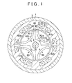
- the IPM motor includes a stator 2 that is fixed to an inner peripheral surface of a housing 1, a motor shaft 3 as a rotating shaft that is supported so as to be rotatable around an axis m, by the housing 1 via a bearing (not illustrated), and a rotor 4 that is integrally fitted to an outer periphery of the motor shaft 3 and is arranged inside the stator 2.
- the stator 2 is formed to be cylindrical around the axis m.
- the stator 2 has a structure in which a plurality of magnetic steel sheets are stacked in an axial direction of the stator 2.
- Six teeth 20 that extend toward a radial direction inner side are formed on an inner peripheral surface of the stator 2.
- a stator coil 21 is wound around each of the teeth 20.
- the rotor 4 has a rotor core 40 that is formed to be cylindrical around the axis m, and four permanent magnets 50 that are embedded in the rotor core 40. As illustrated in FIG. 2 , the rotor core 40 is formed by assembling paired core members 41, 42 in an axial direction (direction parallel to the axis m) of the rotor core 40. Each of the core members 41, 42 has a structure in which a plurality of magnetic steel sheets are stacked in the rotor core axial direction.
- a tubular portion 41a that has a tubular shape around the axis m, and paired projecting portions 41b that project in a radial direction thereof from an outer periphery of the tubular portion 41a are formed in the first core member 41.
- tubular portion radial direction an axial direction of the tubular portion 41a (direction parallel to the axis m) is referred to as a “tubular portion axial direction”
- tubular portion circumferential direction a circumferential direction of the tubular portion 41a (circumferential direction around the axis m) is referred to as a "tubular portion circumferential direction.”
- the motor shaft 3 is inserted into the tubular portion 41a.
- the paired projecting portions 41b are symmetrically arranged about the tubular portion 41a.
- a cross-sectional shape of each of the projecting portions 41b that is orthogonal to the tubular portion axial direction is a substantially fan shape with a central angle of 45°.
- one end surfaces of the tubular portion 41a and both of the projecting portions 41b in the tubular portion axial direction are arranged on one plane, a length of each of the projecting portions 41b in the tubular portion axial direction is twice an axial direction length L of the tubular portion 41a.
- the tubular portion 41a is arranged to be adjacent to, and surrounded by the projecting portions 4 1 b, in an area from one end surface of each of the projecting portions 41b to a middle portion of each of the projecting portions 41b in the tubular portion axial direction.
- an insertion portion 41d that is a space surrounded by the projecting portions 41b is formed in an area from the middle portion of each of the projecting portions 41b in the axial direction to the other end surface of each of the projecting portions 41b.
- the insertion portion 41d is a space into which a tubular portion of the other core member is inserted.
- a substantially fan-shaped arc part of a side surface of the projecting portion 41b that constitutes an outer peripheral surface of the rotor core 40 is referred to as an outer peripheral side surface 41e
- both side surfaces that face the other projecting portions 41b in a rotor core circumferential direction are referred to as circumferential direction side surfaces 41f.
- a magnet insertion hole 41c is formed in each of the projecting portions 41b to extend through the projecting portion 41b in the tubular portion axial direction.
- a cross-sectional shape of the magnet insertion hole 41c that is orthogonal to the tubular portion axial direction is a U shape which is open toward an outer peripheral side.
- the permanent magnet 50 whose cross-sectional shape that is orthogonal to the tubular portion axial direction is a U shape, is inserted into the magnet insertion hole 41 c.
- the permanent magnet 50 is formed of a bond magnet, and has an N pole inside the U shape and an S pole outside the U shape. An N pole is formed on the outer peripheral side surface 41e of each of the projecting portions 41b by the permanent magnet 50.
- a second core member 42 has a shape similar to that of the first core member 41, except that each of the permanent magnets 50 of the second core member 42 has a reverse magnetic pole arrangement.
- the permanent magnet 50 of the second core member 42 has an S pole inside the U shape and an N pole outside the U shape.
- An S pole is formed on an outer peripheral side surface 42e of each of projecting portions 42b by the permanent magnet 50.
- a tubular portion of the second core member 42 is indicated by reference numeral 42a
- a magnet insertion hole is indicated by reference numeral 42c
- an insertion portion is indicated by reference numeral 42d
- a circumferential direction side surface of each of the projecting portions 42b is indicated by reference numeral 42f.
- the paired core members 41, 42 are assembled in such a manner that the tubular portions 41a, 42a are inserted into the insertion portions 42d, 41d, respectively, and each of the projecting portions 41b of the first core member 41 is adjacent to the projecting portions 42b of the second core member 42 in the circumferential direction of the rotor core 40.
- the tubular portion 41a of the first core member 41 and the tubular portion 42a of the second core member 42 are adjacent to each other in the axial direction of the rotor core 40 and are arranged on one straight line.
- the paired core members 41, 42, which are assembled in this manner, constitute the rotor 4.
- the rotor 4 has a four-pole structure in which the N poles and S poles are alternately disposed along an outer peripheral part of the rotor 4.
- a rotating magnetic field is formed in the IPM motor having the above configuration when an alternating current is supplied to the stator coil 21 illustrated in FIG. 1 .
- the rotating magnetic field and a magnetic field that is formed by the permanent magnet 50 act so that torque is applied to the rotor 4 and the motor shaft 3 is rotated.
- the first core member 41 illustrated in FIGS. 3 and 4 is formed by stacking magnetic steel sheets. Then, a magnet material prior to magnetization is embedded in each magnet insertion hole 41c of the molded first core member 41 by injection molding or the like, and then orientation and magnetization are performed on the magnet material by using an orientation and magnetization device 60 illustrated in FIG. 5 .
- the magnet material prior to magnetization is indicated by reference numeral 51.
- the orientation and magnetization device 60 includes a first magnetizing yoke 61, a second magnetizing yoke 62, and a permanent magnet 63.
- the first magnetizing yoke 61 is arranged to face the outer peripheral side surface 41c of the projecting portion 41b.
- the second magnetizing yoke 62 is formed into a C shape such that a part of an annular shape is cut off by forming a space G into which the first core member 41 is inserted.
- the first magnetizing yoke 61 and the permanent magnet 63 are arranged inside the second magnetizing yoke 62.
- An S pole of the permanent magnet 63 is adjacent to an outer surface of the first magnetizing yoke 61 on a side opposite to a surface facing the projecting portion 41b.
- An N pole of the permanent magnet 63 is adjacent to an annular inner peripheral surface of the second magnetizing yoke 62. Both end portions 62a, 62b of the second magnetizing yoke 62 that face each other across the space G are inserted into gaps formed between the paired projecting portions 41b, 41b of the first core member 41, and respectively face the circumferential direction side surfaces 41f, 41f of the projecting portion 41b.
- Magnetic paths are formed in the orientation and magnetization device 60 as indicated by dashed-line arrows in the drawing.
- the magnetic paths are formed so as to be directed from the outer side of the U shape to the inner side of the U shape with respect to each magnet material 51.
- Orientation of the magnet material 51 is performed in this manner, and the inner side of the U shape of the magnet material 51 is magnetized to the N pole and the outer side of the U shape is magnetized to the S pole.
- the magnet material 51 becomes the permanent magnet 50 through the magnetization process, and forming of the first core member 41 is completed.
- each magnet material prior to magnetization that is embedded in the second core member 42 can be magnetized in a similar manner by using an orientation and magnetization device in which the magnetic pole arrangement of the permanent magnet 63 is reversely set with respect to the orientation and magnetization device 60 illustrated in FIG. 5 .
- the manufacturing of the rotor 4 is completed when the first core member 41 and the second core member 42 are assembled after the completion of the magnetization process.
- the first magnetizing yoke 61 can be arranged to be adjacent to the outer peripheral side surface 41e of the projecting portion 41b of the first core member 41, and the second magnetizing yoke 62 can be arranged to be adjacent to the circumferential direction side surfaces 41f of the projecting portion 41b.
- a magnetic flux can be caused to flow in from the circumferential direction side surfaces 41f of the projecting portion 41b, and the magnetic flux can be caused to flow out from the outer peripheral side surface 41e of the projecting portion 41b.
- a surface area of a part through which the magnetic flux flows in and out can be increased, and thus the quantity of the magnetic flux that is supplied to the magnet material 51 prior to magnetization can be increased.
- an orientation rate and a magnetization rate of the permanent magnet 50 that is embedded in the projecting portion 41b are improved.
- a similar effect can be achieved by the second core member 42.
- the orientation rate and the magnetization rate of the permanent magnets 50 of the entire rotor 4 are improved, and therefore, the effective quantity of magnetic flux interlinked to the stator coil 21 can be increased and an output torque of the motor can be improved as well.
- the permanent magnet 50 that forms one magnetic pole at the outer peripheral part of the rotor core 40 is embedded in each of the projecting portions 41b, 42b of the core members 41, 42. In this manner, the magnetic pole of the rotor core 40 can be formed with ease.
- the paired core members 41, 42 have the same shape except for the magnetic pole arrangement of each of the permanent magnets 50 (that is, the magnetic pole arrangement of each of the permanent magnets 50 of the core member 41 is different from the magnetic pole arrangement of each of the permanent magnets 50 of the core member 42).
- the same manufacturing processes can be employed during the manufacturing of the core members 41, 42 except for the magnetization process. As such, manufacturing man-hours for each of the core members 41, 42 can be reduced, and thus manufacturing costs can be reduced for the rotor 4.
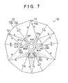
- the first core member 41 illustrated in FIG. 6 is formed by stacking magnetic steel sheets first, for manufacturing the rotor 4 according to the present modification example. Then, a magnet material prior to magnetization is embedded by injection molding or the like in the magnet insertion hole 41c of the formed first core member 41, and then orientation and magnetization are performed on the U-shaped magnet material 51 by using an orientation and magnetization device 70 illustrated in FIG. 7 .
- the orientation and magnetization device 70 includes first magnetizing yokes 71 each of which is arranged between the projecting portions 41b, 41b which are adjacent to each other in the tubular portion circumferential direction, second magnetizing yokes 72 each of which is arranged to face the outer peripheral side surface 41e of the projecting portion 41b, and permanent magnets 73 each of which is arranged between the first magnetizing yoke 71 and the second magnetizing yoke 72.
- the first magnetizing yoke 71 includes an inner side part 71a that is arranged to fill a gap between the projecting portions 41b, 41b in the tubular portion circumferential direction, and an outer side part 71 b that extends from the inner side part 71a toward a tubular portion radial direction outer side.
- the outer side part 71b of the first magnetizing yoke 71 is formed to be sharpened toward the tubular portion radial direction outer side.
- the second magnetizing yoke 72 is arranged to face an area of the outer peripheral side surface 41e of the projecting portion 41b, the area facing an inner peripheral surface of the U-shaped magnet material 51. As is the case with the first magnetizing yoke 71, the second magnetizing yoke 72 is formed to be sharpened toward the tubular portion radial direction outer side from a part facing the outer peripheral side surface 41e of the projecting portion 41b.
- the permanent magnet 73 includes a first permanent magnet 73a that is adjacent to the first magnetizing yoke 71, and a second permanent magnet 73b that is adjacent to the second magnetizing yoke 72.
- the first permanent magnet 73a and the second permanent magnet 73b are adjacent to each other in the tubular portion circumferential direction.
- a part of the first permanent magnet 73a that is adjacent to the first magnetizing yoke 71 is an N pole
- a part of the first permanent magnet 73a that is adjacent to the second permanent magnet 73b is an S pole.
- a part of the second permanent magnet 73b that is adjacent to the second magnetizing yoke 72 is an S pole
- a part of the second permanent magnet 73b that is adjacent to the first permanent magnet 73a is an N pole.
- the permanent magnets 73 are arranged in such a manner that the N poles face each other across the first magnetizing yoke 71 and the S poles face each other across the second magnetizing yoke 72.
- Magnetic paths that are indicated by dashed-line arrows in FIG. 7 are formed in the orientation and magnetization device 70. For convenience, only the magnetic paths that are formed by one of the projecting portions 41b are illustrated in FIG. 7 . As illustrated in FIG. 7 , the magnetic paths are formed so as to be directed from the outer side of the U shape to the inner side of the U shape with respect to each magnet material 51. Orientation is performed on the magnet material 51 through the magnetization process, and the inner side of the U shape of the magnet material 51 is magnetized to the N pole and the outer side of the U shape is magnetized to the S pole. The magnet material 51 becomes the permanent magnet 50 through the magnetization process, and forming of the first core member 41 is competed.
- the magnet material prior to magnetization that is embedded in the second core member 42 can be magnetized in a similar manner by using an orientation and magnetization device in which the magnetic pole arrangement of the first permanent magnet 73a and the second permanent magnet 73b is reversely set with respect to the orientation and magnetization device 70 illustrated in FIG. 7 .
- the manufacturing of the rotor 4 according to the modification example is completed when the first core member 41 and the second core member 42 are assembled after the completion of the magnetization process.
- a cross-sectional shape of the magnet insertion hole 41c formed in the projecting portion 41b of the first core member 41 that is orthogonal to the tubular portion axial direction is a rectangular shape extending in the tubular portion radial direction.
- a cross-sectional shape of the magnet insertion hole 42c formed in the projecting portions 42b of the second core member 42 that is orthogonal to the tubular portion axial direction is a rectangular shape extending in the tubular portion radial direction.
- the permanent magnet 50 whose cross-sectional shape that is orthogonal to the tubular portion axial direction is a rectangular shape is inserted into each of the magnet insertion holes 41 c, 42c.
- Each of the permanent magnets 50 disposed in the first core member 41 has an N pole at a part on one direction a1 side (i.e., on one side) in the tubular portion circumferential direction, and has an S pole at a part on the other direction a2 side (i.e., on the other side) in the tubular portion circumferential direction.
- each of the permanent magnets 50 disposed in the second core member 42 has an S pole at a part on one direction a1 side (i.e., on the one side) in the tubular portion circumferential direction, and has an N pole at a part on the other direction a2 side (i.e., on the other side) in the tubular portion circumferential direction.
- the second core member 42 according to the embodiment has a structure obtained by turning the first core member 41 upside down. In other words, the first core member 41 and the second core member 42 according to this embodiment have the same structure.
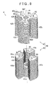
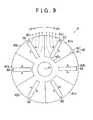
- the rotor 4 illustrated in FIG. 9 is formed by assembling the first core member 41 and the second core member 42 with the above-mentioned shapes.
- the permanent magnets 50 are arranged radially, and the permanent magnet 50 disposed in the first core member 41 and the permanent magnet 50 disposed in the second core member 42 are arranged to face each other so that magnetic poles having the same polarity face each other.
- An N pole is formed at the outer peripheral part of the rotor core 40 by a part where the N poles of the permanent magnets 50 face each other
- an S pole is formed at the outer peripheral part of the rotor core 40 by a part where the S poles of the permanent magnets 50 face each other.
- the rotor 4 has a six-pole structure in which the N poles and S poles are alternately disposed along the circumferential direction at the outer peripheral part.
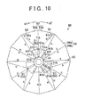
- the first core member 41 illustrated in FIG. 8 is formed by stacking magnetic steel sheets first, for manufacturing the rotor 4. Then, a magnet material prior to magnetization is embedded by injection molding or the like in the magnet insertion hole 41c of the formed first core member 41, and then orientation and magnetization are performed on the magnet material 51 by using an orientation and magnetization device 80 illustrated in FIG. 10 .
- FIG. 10 one side surface of the magnet material 51 in the tubular portion circumferential direction is indicated by reference numeral 51a, and the other side surface is indicated by reference numeral 51b.
- the orientation and magnetization device 80 includes a pair of first magnetizing yoke 81 and a second magnetizing yoke 82 that are arranged such that each projecting portion 41 b is sandwiched between the first magnetizing yoke 81 and the second magnetizing yoke 82 in the tubular portion circumferential direction, and a first permanent magnet 83 and a second permanent magnet 84 that are arranged to fill a gap between the first magnetizing yoke 81 and the second magnetizing yoke 82.
- the first magnetizing yoke 81 is formed to cover the one circumferential direction side surface 41f of the projecting portion 41b, which faces the one side surface 51a of the magnet material 51 and an area of the outer peripheral side surface 41e of the projecting portion 41b, which faces the one side surface 51a of the magnet material 51.
- the second magnetizing yoke 82 is formed to cover the other circumferential direction side surface 41f of the projecting portion 41b, which faces the other side surface 51b of the magnet material 51, and an area of the outer peripheral side surface 41e of the projecting portion 41 b, which faces the other side surface 51b of the magnet material 51.
- first magnetizing yoke 81 and the second magnetizing yoke 82 respectively have extending portions 81a, 82a that extend to the tubular portion radial direction outer side from parts facing the outer peripheral side surface 41e of the projecting portion 41b.
- the extending portions 81a, 82a are formed to be sharpened toward the tubular portion radial direction outer side.
- the first permanent magnet 83 is arranged in an area outside the outer peripheral side surface 41 e of the projecting portion 41 b in a gap formed between the first magnetizing yoke 81 and the second magnetizing yoke 82 in the tubular portion circumferential direction.
- the first permanent magnet 83 includes a permanent magnet 83a that is adjacent to the first magnetizing yoke 81, and a permanent magnet 83b that is adjacent to the second magnetizing yoke 82.
- the permanent magnets 83a, 83b are adjacent to each other in the tubular portion circumferential direction.
- a part of the permanent magnet 83a that is adjacent to the first magnetizing yoke 81 is an N pole, and a part of the permanent magnet 83a that is adjacent to the permanent magnet 83b is an S pole.
- a part of the permanent magnet 83b that is adjacent to the second magnetizing yoke 82 is an S pole, and a part of the permanent magnet 83b that is adjacent to the permanent magnet 83a is an N pole.
- the second permanent magnet 84 is arranged in an area between the projecting portions 41b, 41b that are adjacent to each other in the tubular portion circumferential direction in the gap formed between the first magnetizing yoke 81 and the second magnetizing yoke 82.
- the second permanent magnet 84 includes a permanent magnet 84a that is adjacent to the first magnetizing yoke 81, and a permanent magnet 84b that is adjacent to the second magnetizing yoke 82.
- the permanent magnets 84a, 84b are adjacent to each other in the tubular portion circumferential direction.
- a part of the one permanent magnet 84a that is adjacent to the first magnetizing yoke 81 is an N pole, and a part of the permanent magnet 84a that is adjacent to the other permanent magnet 84b is an S pole.
- a part of the other permanent magnet 84b that is adjacent to the second magnetizing yoke 82 is an S pole, and a part of the other permanent magnet 84b that is adjacent to the one permanent magnet 84a is an N pole.
- the first permanent magnet 83 and the second permanent magnet 84 are arranged in such a manner that the N poles face each other across the first magnetizing yoke 81 and the S poles face each other across the second magnetizing yoke 82.
- Magnetic paths that are indicated by dashed-line arrows in FIG. 10 are formed in the orientation and magnetization device 80. For convenience, only the magnetic paths that are formed by one of the projecting portions 41b are illustrated in FIG 10 . As illustrated in FIG. 10 , the magnetic paths are formed so as to be directed from the one side surface 51a of the magnet material 51 to the other side surface 51b. Orientation is performed on the magnet material 51 in this manner, and the one side surface 51a of the magnet material 51 is magnetized to the S pole and the other side surface 51b is magnetized to the N pole. The magnet material 51 becomes the permanent magnet 50 through the magnetization process, and forming of the first core member 41 is completed.
- the second core member 42 has the same structure as the structure of the first core member 41, the second core member 42 can be formed by a method similar to the method in which the first core member 41 is formed.
- the manufacturing of the rotor 4 illustrated in FIGS. 8 and 9 is completed when the first core member 41 and the second core member 42 are assembled after the completion of the magnetization process.
- the following advantageous effects can be achieved in addition to an advantageous effect similar to the advantageous effect of the first embodiment described in the (1).
- the first core member 41 and the second core member 42 have the same structure, the first core member 41 and the second core member 42 can be manufactured by using the orientation and magnetization device 80 illustrated in FIG. 10 . Accordingly, the manufacturing costs can be reduced.
- the magnetic fields formed by the permanent magnets 50 repel each other between a set of the permanent magnets 50, 50 whose N poles face each other, and thus magnetic flux exchange does not occur therebetween. Accordingly, the magnetic flux that passes through a boundary part of the projecting portions 41b, 42b adjacent to each other in the circumferential direction of the rotor core 40 can be decreased. In addition, the same effect is achieved between a set of the permanent magnets 50, 50 whose S poles face each other.
- the boundary part of the projecting portions 41b, 42b is unlikely to act as a magnetoresistance against the magnetic paths formed by the one set of permanent magnets 50, 50, and thus a reduction in magnetic flux density at the outer peripheral surface of the rotor core 40 can be suppressed. As a result, the output torque of the motor can be ensured.
- the first magnetizing yoke 71 is adjacent to the circumferential direction side surface 41f of the projecting portion 41b in the orientation and magnetization device 70 according to the modification example of the first embodiment.
- the N pole of the permanent magnet may be directly adjacent to the circumferential direction side surface 41f of the projecting portion 41b.
- the S pole of the permanent magnet may be directly adjacent to the outer peripheral side surface 41e of the projecting portion 41b.
- the first magnetizing yoke 71 and the second magnetizing yoke 72 can be excluded.
- a similar configuration can be employed in the orientation and magnetization device 60 of the first embodiment and the orientation and magnetization device 80 of the second embodiment as well.
- each of the orientation and magnetization devices 60, 70, 80 may have a magnetic path forming unit that is arranged to face the outer peripheral side surface 41e and the circumferential direction side surface 41f of the projecting portion 41b such that the magnetic path is formed to extend through the magnet material prior to magnetization which is embedded in the projecting portion 41b by the magnetic path forming unit.
- the magnetizing yoke when used, the magnetic flux generated from the permanent magnet can be collected and supplied to the magnet material prior to magnetization because saturation magnetization of a yoke is generally larger than saturation magnetization of a permanent magnet. Accordingly, it is preferable that the magnetizing yoke be used in view of the magnetization rate of the magnet material.
- Either one of the first permanent magnet 83 and the second permanent magnet 84 may be omitted in the orientation and magnetization device 80 according to the second embodiment. Even in this configuration, the magnet material 51 can be magnetized.
- FIG. 11 is a modification example of the orientation and magnetization device 70 illustrated in FIG. 7 , and illustrates a structure of an orientation and magnetization device 90 in which the magnetization coil is used.
- the orientation and magnetization device 90 includes a magnetizing yoke 91, and magnetization coils 92 that are wound around portions of the magnetizing yoke 91.
- the magnetizing yoke 91 includes an annular portion 91a that is arranged to surround the first core member 41, first extending portions 91 b each of which is formed to extend from an inner wall surface of the annular portion 91a to the gap between the projecting portions 41b, 41b, and second extending portions 91c each of which is formed to extend from the inner wall surface of the annular portion 91a to the outer peripheral side surface 41e of the projecting portion 41b.
- the magnetization coil 92 is wound around each of the first extending portion 91b and the second extending portion 91c.
- An electric current is supplied to the magnetization coil 92 wound around the first extending portion 91b such that a part of the first extending portion 91b arranged between the projecting portions 41b, 41 b is an N pole.
- An electric current is supplied to the magnetization coil 92 wound around the second extending portion 91 c such that a part of the second extending portion 91c facing the outer peripheral side surface 41e of the projecting portion 41b is an S pole.
- each of the core members 41, 42 can be appropriately changed.
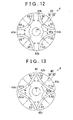
- paired permanent magnets 52, 53 which face each other so that magnetic poles with different polarities face each other in the rotor core circumferential direction, may be embedded in each of the projecting portions 41b, 42b of the core members 41, 42.
- the permanent magnet 52 that is embedded in the projecting portion 41b of the first core member 41 may be arranged to face the permanent magnet 52 embedded in the projecting portion 42b of the second core member 42 which is adjacent to the first core member 41 in the circumferential direction of the rotor core 40 so that the N poles face each other.
- the permanent magnet 53 that is embedded in the projecting portion 41b of the first core member 41 may be arranged to face the permanent magnet 53 embedded in the projecting portion 42b of the second core member 42 which is adjacent to the first core member 41 in the circumferential direction of the rotor core 40 so that the S poles face each other.
- the N pole may be formed at the outer peripheral part of the rotor core 40 by using a set of the permanent magnets 52, 52 which are adjacent in the rotor core circumferential direction
- the S pole may be formed at the outer peripheral part of the rotor core 40 by using a set of the permanent magnets 53, 53 which are adjacent in the rotor core circumferential direction.
- rotor core radial direction outer side parts of the paired permanent magnets 52, 53 embedded in each of the projecting portions 41b, 42b may be connected with each other.
- orientation and magnetization can be performed on the magnet material prior to magnetization by using the orientation and magnetization device 80 according to the second embodiment illustrated in FIG. 10 .
- the number of the projecting portions 41b, 42b of the respective core members 41, 42 is changed according to the number of the magnetic poles of the rotor 4, the number of the projecting portions 41b, 42b of the respective core members 41, 42 is increased as the number of the magnetic poles of the rotor 4 is increased. Accordingly, the gap between the projecting portions 41b, 41b of the first core member 41 and the gap between the projecting portions 42b, 42b of the second core member 42 are narrowed, and the arrangement of the magnetizing yoke becomes difficult.
- the member of the projecting portions of each of the core members may be decreased by setting the number of the core members constituting the rotor 4 to three or more.
- the rotor core 40 is configured to include three core members 43, 44, 45 as illustrated in FIG. 14 .
- tubular portions of the core members 43, 44, 45 are respectively indicated by reference numerals 43a, 44a, 45a
- projecting portions are respectively indicated by reference numerals 43b, 44b, 45b
- magnet insertion holes are respectively indicated by reference numerals 43c, 44c, 45c.
- the shape of the permanent magnet 50 is not limited to the shape in each of the embodiments.
- the cross-sectional shape of the permanent magnet 50 that is orthogonal to the tubular portion axial direction may be, for example, a V shape or an angular U shape.
- the bond magnet is used as the permanent magnet 50 in each of the embodiments, but a sintered magnet, a compression molding magnet, and the like may be used as well.
- the magnet material prior to magnetization is embedded in the magnet insertion holes 41 c, 42c of the core members 41, 42 and then orientation and magnetization are performed on the magnet material by using the orientation and magnetization device 60, 70, or 80, but the present invention is not limited thereto.
- orientation and magnetization may be performed on the magnet material during injection of the magnet material into the magnet insertion holes 41c, 42c of the core members 41, 42 in a state where the core members 41, 42 are arranged in the orientation and magnetization device 60, 70, or 80.
- the orientation and magnetization device that performs orientation and magnetization on the magnet material 51 has been described, but the device may perform only orientation or only magnetization on the magnet material 51.
- a material of the core members 41, 42 is not limited to the magnetic steel sheet.
- a soft magnetic material such as an electromagnetic soft iron can be used as the material.
- the permanent magnets 73, 83, 84 may be configured to have one permanent magnet instead of being configured to include the paired permanent magnets 73a, 73b ⁇ 83a, 83b ⁇ 84a, 84b.
Landscapes
- Engineering & Computer Science (AREA)
- Power Engineering (AREA)
- Manufacturing & Machinery (AREA)
- Permanent Field Magnets Of Synchronous Machinery (AREA)
- Iron Core Of Rotating Electric Machines (AREA)
- Manufacture Of Motors, Generators (AREA)
Abstract
Description
- The invention relates to a magnet-embedded rotor, a method for manufacturing a magnet-embedded rotor, and an orientation and magnetization device.
- Interior permanent magnet motors (IPM motors) having a structure in which a permanent magnet for a field is embedded in a rotor are known. A method described in Japanese Patent Application Publication No.
2010-193587 JP 2010-193587 A JP 2010-193587 A - In a case where the magnetic flux is supplied from the outer peripheral surface of the rotor core by the magnetization device as described in
JP 2010-193587 A - The invention provides a magnet-embedded rotor, a method for manufacturing a magnet-embedded rotor, and an orientation and magnetization device, which make it possible to improve a magnetization rate of a permanent magnet.
- A magnet-embedded rotor according to an aspect of the invention includes a cylindrical rotor core that rotates together with a rotating shaft; and permanent magnets embedded in the rotor core, wherein the rotor core includes a plurality of core members, and each of the plurality of core members includes a tubular portion into which the rotating shaft is inserted and a plurality of projecting portions formed to project in a radial direction of the tubular portion from an outer periphery of the tubular portion and arranged apart from each other in a circumferential direction of the tubular portion, wherein the rotor core is formed by assembling the plurality of core members such that the tubular portions of the plurality of core members are arranged on one straight line and each of the plurality of projecting portions of each of the plurality of core members is adjacent to the projecting portion of the other core member in a circumferential direction of the rotor core, and wherein the permanent magnet is embedded in each of the plurality of projecting portions of each of the plurality of core members.
- A method for manufacturing the magnet-embedded rotor according to the above-mentioned aspect includes a magnetization process in which a magnet material prior to magnetization embedded in each of the plurality of projecting portions of each of the plurality of core members is magnetized to produce the permanent magnet; and a process in which the plurality of core members are assembled in an axial direction of the rotor core, after the magnetization process is performed.
- According to the configuration and the manufacturing method described above, an orientation and magnetization device can be arranged in a gap formed between the projecting portions of the core member. Thus, the orientation and magnetization device can be arranged to face not only the side surface of the projecting portion constituting the outer peripheral surface of the rotor core but also the side surface of the projecting portion in the circumferential direction of the rotor core. Accordingly, as compared to a case of the related art where the magnetic flux flows in and out only via an outer peripheral surface of a rotor core, a surface area of a part through which the magnetic flux flows in and out can be increased, and thus the quantity of the magnetic flux that is supplied to the permanent magnet can be increased. Thus, a magnetization rate of the permanent magnet embedded in the projecting portion can be improved. As a result, the magnetization rate of the permanent magnets of the entire rotor can be improved.
- In the magnet-embedded rotor according to the above-mentioned aspect, the permanent magnet forming one magnetic pole at an outer peripheral part of the rotor core may be embedded in each of the projecting portions. According to the configuration, the magnetic pole of the rotor can be formed with ease.
- In the magnet-embedded rotor according to the above-mentioned aspect, the permanent magnet embedded in the projecting portion of the core member may be arranged to face the permanent magnet embedded in the projecting portion of the other core member adjacent to the core member in the circumferential direction of the rotor core so that magnetic poles having a same polarity face each other; and one magnetic pole may be formed at an outer peripheral part of the rotor core by a set of the permanent magnets that are arranged to face each other so that the magnet poles having the same polarity face each other.
- According to the configuration, a boundary part of the projecting portions of the core members is positioned between a set of the permanent magnets that face each other so that the poles with the same polarity face each other. The magnetic fields formed by the permanent magnets repel each other between the set of the permanent magnets that face each other so that the poles having the same polarity face each other, and thus magnetic flux exchange does not occur therebetween. Accordingly, the magnetic flux that passes through the boundary part of the projecting portions of the core members adjacent to each other can be decreased. Therefore, the boundary part of the projecting portions is unlikely to act as a magnetoresistance against the magnetic paths formed by the set of permanent magnets, and thus a reduction in magnetic flux density at the outer peripheral surface of the rotor core can be suppressed. As a result, the output torque of the motor can be ensured.
- In a case where the rotor core is formed of two core members, the rotor core is completed by just assembling the two core members, and thus the manufacturing of the rotor core is facilitated. However, as the number of magnetic poles of the rotor increases, the number of permanent magnets for forming the magnetic poles increases. Therefore, the number of projecting portions formed in one core member is inevitably increased. When the number of projecting portions formed in one core member increases, the gap between the projecting portions is narrowed, and thus it is difficult to arrange the orientation and magnetization device between the projecting portions.
- In the magnet-embedded rotor according to the above-mentioned aspect, the number of the plurality of core members assembled to form the rotor core may be three or more. According to the configuration, the number of projecting portions formed in one core member is small as compared to a case where the rotor core is formed of two core members, and thus the gap between the projecting portions can be widened. As such, the orientation and magnetization device can be arranged between the projecting portions with ease.
- In addition, in the magnet-embedded rotor according to the above-mentioned aspect, the plurality of core members may have a same shape except for a magnetic pole arrangement of each of the permanent magnets. According to the configuration, the same manufacturing processes can be employed except for the magnetization process during the manufacturing of each of the core members. Therefore, manufacturing man-hours for the core members can be reduced, and thus manufacturing costs can be reduced for the rotor.
- An orientation and magnetization device that performs at least one of orientation and magnetization on a magnet material prior to magnetization embedded in each of the plurality of core members may include a magnetic path forming unit that is arranged to face an outer peripheral side surface and a circumferential direction side surface of each of the plurality of projecting portions, and forms a magnetic path extending through the magnet material prior to magnetization embedded in the projecting portion, the outer peripheral side surface being a side surface constituting an outer peripheral part of the rotor core, and the circumferential direction side surface being a side surface facing the other projecting portion in the circumferential direction of the rotor core.
- In the orientation and magnetization device, the magnetic path forming unit may be configured to include a magnetizing yoke arranged to face the outer peripheral side surface and the circumferential direction side surface of the projecting portion, and a magnetic flux generating unit adjacent to the magnetizing yoke.
- According to the configuration, the magnetic flux generated by the magnetic flux generating unit can be collected by the magnetizing yoke and supplied to the projecting portion, and thus the quantity of the magnetic flux supplied to the projecting portion can be increased as compared to a case where the magnetic flux generating unit directly faces the outer peripheral side surface and the circumferential direction side surface of the projecting portion. Accordingly, at least one of an orientation rate and a magnetization rate of the permanent magnet that is embedded in the projecting portion can be increased.
- According to the magnet-embedded rotor, the method for manufacturing a magnet-embedded rotor, and the orientation and magnetization device, the magnetization rate of the permanent magnet can be improved.
- Features, advantages, and technical and industrial significance of exemplary embodiments of the invention will be described below with reference to the accompanying drawings, in which like numerals denote like elements, and wherein:
-
FIG. 1 is a cross-sectional view illustrating a cross-sectional structure of an IPM motor using a magnet-embedded rotor according to a first embodiment; -
FIG. 2 is a perspective view illustrating an exploded perspective structure of the magnet-embedded rotor according to the first embodiment; -
FIG 3 is a plan view illustrating a planar structure of a core member of the magnet-embedded rotor according to the first embodiment; -
FIG. 4 is a front view illustrating a front structure of the core member of the magnet-embedded rotor according to the first embodiment; -
FIG 5 is a plan view illustrating a method for magnetizing the core member of the magnet-embedded rotor according to the first embodiment; -
FIG. 6 is a perspective view illustrating an exploded perspective structure of a magnet-embedded rotor according to a modification example of the first embodiment; -
FIG. 7 is a plan view illustrating a method for magnetizing a core member of the magnet-embedded rotor according to the modification example of the first embodiment; -
FIG 8 is a perspective view illustrating an exploded perspective structure of a magnet-embedded rotor according to a second embodiment; -
FIG. 9 is a plan view illustrating a planar structure of the magnet-embedded rotor according to the second embodiment; -
FIG. 10 is a plan view illustrating a method for magnetizing a core member of the magnet-embedded rotor according to the second embodiment; -
FIG 11 is a plan view illustrating a method for magnetizing the core member of the magnet-embedded rotor according to the modification example of the first embodiment; -
FIG. 12 is a plan view illustrating a planar structure of a magnet-embedded rotor according to another modification example; -
FIG. 13 is a plan view illustrating a planar structure of a magnet-embedded rotor according to another modification example; and -
FIG. 14 is a perspective view illustrating an exploded perspective structure of a magnet-embedded rotor according to another modification example. - (First Embodiment) Hereinafter, a magnet-embedded rotor according to a first embodiment will be described. Firstly, a structure of an IPM motor that uses the magnet-embedded rotor according to the present embodiment will be described.
- As illustrated in
FIG. 1 , the IPM motor includes astator 2 that is fixed to an inner peripheral surface of ahousing 1, amotor shaft 3 as a rotating shaft that is supported so as to be rotatable around an axis m, by thehousing 1 via a bearing (not illustrated), and arotor 4 that is integrally fitted to an outer periphery of themotor shaft 3 and is arranged inside thestator 2. - The
stator 2 is formed to be cylindrical around the axis m. Thestator 2 has a structure in which a plurality of magnetic steel sheets are stacked in an axial direction of thestator 2. Six teeth 20 that extend toward a radial direction inner side are formed on an inner peripheral surface of thestator 2. A stator coil 21 is wound around each of the teeth 20. - The
rotor 4 has arotor core 40 that is formed to be cylindrical around the axis m, and fourpermanent magnets 50 that are embedded in therotor core 40. As illustrated inFIG. 2 , therotor core 40 is formed by assembling pairedcore members rotor core 40. Each of thecore members - As illustrated in
FIGS. 3 and 4 , atubular portion 41a that has a tubular shape around the axis m, and paired projectingportions 41b that project in a radial direction thereof from an outer periphery of thetubular portion 41a are formed in thefirst core member 41. Hereinafter, the radial direction of thetubular portion 41a (direction orthogonal to the axis m) is referred to as a "tubular portion radial direction," an axial direction of thetubular portion 41a (direction parallel to the axis m) is referred to as a "tubular portion axial direction," and a circumferential direction of thetubular portion 41a (circumferential direction around the axis m) is referred to as a "tubular portion circumferential direction." Themotor shaft 3 is inserted into thetubular portion 41a. The paired projectingportions 41b are symmetrically arranged about thetubular portion 41a. A cross-sectional shape of each of the projectingportions 41b that is orthogonal to the tubular portion axial direction is a substantially fan shape with a central angle of 45°. As illustrated inFIG 4 , one end surfaces of thetubular portion 41a and both of the projectingportions 41b in the tubular portion axial direction are arranged on one plane, a length of each of the projectingportions 41b in the tubular portion axial direction is twice an axial direction length L of thetubular portion 41a. Accordingly, thetubular portion 41a is arranged to be adjacent to, and surrounded by the projectingportions 4 1 b, in an area from one end surface of each of the projectingportions 41b to a middle portion of each of the projectingportions 41b in the tubular portion axial direction. In addition, aninsertion portion 41d that is a space surrounded by the projectingportions 41b is formed in an area from the middle portion of each of the projectingportions 41b in the axial direction to the other end surface of each of the projectingportions 41b. Theinsertion portion 41d is a space into which a tubular portion of the other core member is inserted. Hereinafter, as illustrated inFIG. 3 , a substantially fan-shaped arc part of a side surface of the projectingportion 41b that constitutes an outer peripheral surface of therotor core 40 is referred to as an outerperipheral side surface 41e, and both side surfaces that face the other projectingportions 41b in a rotor core circumferential direction are referred to as circumferential direction side surfaces 41f. - As illustrated in
FIG. 3 , amagnet insertion hole 41c is formed in each of the projectingportions 41b to extend through the projectingportion 41b in the tubular portion axial direction. A cross-sectional shape of themagnet insertion hole 41c that is orthogonal to the tubular portion axial direction is a U shape which is open toward an outer peripheral side. Thepermanent magnet 50, whose cross-sectional shape that is orthogonal to the tubular portion axial direction is a U shape, is inserted into themagnet insertion hole 41 c. Thepermanent magnet 50 is formed of a bond magnet, and has an N pole inside the U shape and an S pole outside the U shape. An N pole is formed on the outerperipheral side surface 41e of each of the projectingportions 41b by thepermanent magnet 50. - As illustrated in
FIG. 2 , asecond core member 42 has a shape similar to that of thefirst core member 41, except that each of thepermanent magnets 50 of thesecond core member 42 has a reverse magnetic pole arrangement. In other words, thepermanent magnet 50 of thesecond core member 42 has an S pole inside the U shape and an N pole outside the U shape. An S pole is formed on an outerperipheral side surface 42e of each of projectingportions 42b by thepermanent magnet 50. In addition, inFIG. 2 , a tubular portion of thesecond core member 42 is indicated byreference numeral 42a, a magnet insertion hole is indicated byreference numeral 42c, an insertion portion is indicated byreference numeral 42d, and a circumferential direction side surface of each of the projectingportions 42b is indicated byreference numeral 42f. - The paired
core members tubular portions insertion portions portions 41b of thefirst core member 41 is adjacent to the projectingportions 42b of thesecond core member 42 in the circumferential direction of therotor core 40. In this case, thetubular portion 41a of thefirst core member 41 and thetubular portion 42a of thesecond core member 42 are adjacent to each other in the axial direction of therotor core 40 and are arranged on one straight line. The pairedcore members rotor 4. In this manner, therotor 4 has a four-pole structure in which the N poles and S poles are alternately disposed along an outer peripheral part of therotor 4. - A rotating magnetic field is formed in the IPM motor having the above configuration when an alternating current is supplied to the stator coil 21 illustrated in
FIG. 1 . The rotating magnetic field and a magnetic field that is formed by thepermanent magnet 50 act so that torque is applied to therotor 4 and themotor shaft 3 is rotated. - Next, a method for manufacturing the
rotor 4 and effects thereof will be described. Firstly, during the manufacturing of therotor 4, thefirst core member 41 illustrated inFIGS. 3 and 4 is formed by stacking magnetic steel sheets. Then, a magnet material prior to magnetization is embedded in eachmagnet insertion hole 41c of the moldedfirst core member 41 by injection molding or the like, and then orientation and magnetization are performed on the magnet material by using an orientation andmagnetization device 60 illustrated inFIG. 5 . InFIG. 5 , the magnet material prior to magnetization is indicated byreference numeral 51. - As illustrated in
FIG 5 , the orientation andmagnetization device 60 includes a first magnetizingyoke 61, a second magnetizingyoke 62, and apermanent magnet 63. The first magnetizingyoke 61 is arranged to face the outerperipheral side surface 41c of the projectingportion 41b. The second magnetizingyoke 62 is formed into a C shape such that a part of an annular shape is cut off by forming a space G into which thefirst core member 41 is inserted. The first magnetizingyoke 61 and thepermanent magnet 63 are arranged inside the second magnetizingyoke 62. An S pole of thepermanent magnet 63 is adjacent to an outer surface of the first magnetizingyoke 61 on a side opposite to a surface facing the projectingportion 41b. An N pole of thepermanent magnet 63 is adjacent to an annular inner peripheral surface of the second magnetizingyoke 62. Both end portions 62a, 62b of the second magnetizingyoke 62 that face each other across the space G are inserted into gaps formed between the paired projectingportions first core member 41, and respectively face the circumferential direction side surfaces 41f, 41f of the projectingportion 41b. - Magnetic paths are formed in the orientation and
magnetization device 60 as indicated by dashed-line arrows in the drawing. In other words, the magnetic paths are formed so as to be directed from the outer side of the U shape to the inner side of the U shape with respect to eachmagnet material 51. Orientation of themagnet material 51 is performed in this manner, and the inner side of the U shape of themagnet material 51 is magnetized to the N pole and the outer side of the U shape is magnetized to the S pole. Themagnet material 51 becomes thepermanent magnet 50 through the magnetization process, and forming of thefirst core member 41 is completed. When thesecond core member 42 is formed, each magnet material prior to magnetization that is embedded in thesecond core member 42 can be magnetized in a similar manner by using an orientation and magnetization device in which the magnetic pole arrangement of thepermanent magnet 63 is reversely set with respect to the orientation andmagnetization device 60 illustrated inFIG. 5 . The manufacturing of therotor 4 is completed when thefirst core member 41 and thesecond core member 42 are assembled after the completion of the magnetization process. - According to the
rotor 4, the method for manufacturing therotor 4, and the orientation andmagnetization device 60 described above, the following advantageous effects described in (1) to (3) can be achieved. (1) According to the method for manufacturing therotor 4 illustrated inFIG. 5 , the first magnetizingyoke 61 can be arranged to be adjacent to the outerperipheral side surface 41e of the projectingportion 41b of thefirst core member 41, and the second magnetizingyoke 62 can be arranged to be adjacent to the circumferential direction side surfaces 41f of the projectingportion 41b. In this manner, a magnetic flux can be caused to flow in from the circumferential direction side surfaces 41f of the projectingportion 41b, and the magnetic flux can be caused to flow out from the outerperipheral side surface 41e of the projectingportion 41b. Accordingly, as compared to a case of the related art where the magnetic flux flows in and out only via an outer peripheral surface of a rotor core, a surface area of a part through which the magnetic flux flows in and out can be increased, and thus the quantity of the magnetic flux that is supplied to themagnet material 51 prior to magnetization can be increased. In this manner, an orientation rate and a magnetization rate of thepermanent magnet 50 that is embedded in the projectingportion 41b are improved. In addition, a similar effect can be achieved by thesecond core member 42. As a result, the orientation rate and the magnetization rate of thepermanent magnets 50 of theentire rotor 4 are improved, and therefore, the effective quantity of magnetic flux interlinked to the stator coil 21 can be increased and an output torque of the motor can be improved as well. - (2) The
permanent magnet 50 that forms one magnetic pole at the outer peripheral part of therotor core 40 is embedded in each of the projectingportions core members rotor core 40 can be formed with ease. - (3) The paired
core members permanent magnets 50 of thecore member 41 is different from the magnetic pole arrangement of each of thepermanent magnets 50 of the core member 42). In this manner, the same manufacturing processes can be employed during the manufacturing of thecore members core members rotor 4. - (Modification Example) Next, a modification example of the magnet-embedded
rotor 4 according to the first embodiment will be described. As illustrated inFIG 6 , in this modification example, three substantially fan-shaped projectingportions 41b are formed at equal angular intervals at an outer peripheral part of thetubular portion 41a of thefirst core member 41. Similarly, three substantially fan-shaped projectingportions 42b are formed at equal angular intervals at an outer peripheral part of thetubular portion 42a of thesecond core member 42. Therotor 4 that has six magnetic poles can be formed by assembling thefirst core member 41 and thesecond core member 42. When the number of projectingportions core members rotor 4 can be changed with ease. - Next, a method for manufacturing the
rotor 4 illustrated inFIG. 6 will be described. As in the first embodiment, thefirst core member 41 illustrated inFIG. 6 is formed by stacking magnetic steel sheets first, for manufacturing therotor 4 according to the present modification example. Then, a magnet material prior to magnetization is embedded by injection molding or the like in themagnet insertion hole 41c of the formedfirst core member 41, and then orientation and magnetization are performed on theU-shaped magnet material 51 by using an orientation andmagnetization device 70 illustrated inFIG. 7 . - As illustrated in
FIG. 7 , the orientation andmagnetization device 70 includes first magnetizingyokes 71 each of which is arranged between the projectingportions peripheral side surface 41e of the projectingportion 41b, andpermanent magnets 73 each of which is arranged between the first magnetizingyoke 71 and the second magnetizingyoke 72. - The first magnetizing
yoke 71 includes aninner side part 71a that is arranged to fill a gap between the projectingportions outer side part 71 b that extends from theinner side part 71a toward a tubular portion radial direction outer side. Theouter side part 71b of the first magnetizingyoke 71 is formed to be sharpened toward the tubular portion radial direction outer side. The second magnetizingyoke 72 is arranged to face an area of the outerperipheral side surface 41e of the projectingportion 41b, the area facing an inner peripheral surface of theU-shaped magnet material 51. As is the case with the first magnetizingyoke 71, the second magnetizingyoke 72 is formed to be sharpened toward the tubular portion radial direction outer side from a part facing the outerperipheral side surface 41e of the projectingportion 41b. - The
permanent magnet 73 includes a firstpermanent magnet 73a that is adjacent to the first magnetizingyoke 71, and a secondpermanent magnet 73b that is adjacent to the second magnetizingyoke 72. The firstpermanent magnet 73a and the secondpermanent magnet 73b are adjacent to each other in the tubular portion circumferential direction. A part of the firstpermanent magnet 73a that is adjacent to the first magnetizingyoke 71 is an N pole, and a part of the firstpermanent magnet 73a that is adjacent to the secondpermanent magnet 73b is an S pole. A part of the secondpermanent magnet 73b that is adjacent to the second magnetizingyoke 72 is an S pole, and a part of the secondpermanent magnet 73b that is adjacent to the firstpermanent magnet 73a is an N pole. In this manner, thepermanent magnets 73 are arranged in such a manner that the N poles face each other across the first magnetizingyoke 71 and the S poles face each other across the second magnetizingyoke 72. - Magnetic paths that are indicated by dashed-line arrows in
FIG. 7 are formed in the orientation andmagnetization device 70. For convenience, only the magnetic paths that are formed by one of the projectingportions 41b are illustrated inFIG. 7 . As illustrated inFIG. 7 , the magnetic paths are formed so as to be directed from the outer side of the U shape to the inner side of the U shape with respect to eachmagnet material 51. Orientation is performed on themagnet material 51 through the magnetization process, and the inner side of the U shape of themagnet material 51 is magnetized to the N pole and the outer side of the U shape is magnetized to the S pole. Themagnet material 51 becomes thepermanent magnet 50 through the magnetization process, and forming of thefirst core member 41 is competed. When thesecond core member 42 is formed, the magnet material prior to magnetization that is embedded in thesecond core member 42 can be magnetized in a similar manner by using an orientation and magnetization device in which the magnetic pole arrangement of the firstpermanent magnet 73a and the secondpermanent magnet 73b is reversely set with respect to the orientation andmagnetization device 70 illustrated inFIG. 7 . The manufacturing of therotor 4 according to the modification example is completed when thefirst core member 41 and thesecond core member 42 are assembled after the completion of the magnetization process. - (Second Embodiment) Next, a magnet-embedded rotor according to a second embodiment will be described. The following description focuses on differences between the second embodiment and the modification example of the first embodiment.
- As illustrated in
FIG 8 , in the second embodiment, a cross-sectional shape of themagnet insertion hole 41c formed in the projectingportion 41b of thefirst core member 41 that is orthogonal to the tubular portion axial direction is a rectangular shape extending in the tubular portion radial direction. Similarly, a cross-sectional shape of themagnet insertion hole 42c formed in the projectingportions 42b of thesecond core member 42 that is orthogonal to the tubular portion axial direction is a rectangular shape extending in the tubular portion radial direction. Thepermanent magnet 50 whose cross-sectional shape that is orthogonal to the tubular portion axial direction is a rectangular shape is inserted into each of the magnet insertion holes 41 c, 42c. Each of thepermanent magnets 50 disposed in thefirst core member 41 has an N pole at a part on one direction a1 side (i.e., on one side) in the tubular portion circumferential direction, and has an S pole at a part on the other direction a2 side (i.e., on the other side) in the tubular portion circumferential direction. In contrast, each of thepermanent magnets 50 disposed in thesecond core member 42 has an S pole at a part on one direction a1 side (i.e., on the one side) in the tubular portion circumferential direction, and has an N pole at a part on the other direction a2 side (i.e., on the other side) in the tubular portion circumferential direction. Thesecond core member 42 according to the embodiment has a structure obtained by turning thefirst core member 41 upside down. In other words, thefirst core member 41 and thesecond core member 42 according to this embodiment have the same structure. - The
rotor 4 illustrated inFIG. 9 is formed by assembling thefirst core member 41 and thesecond core member 42 with the above-mentioned shapes. As illustrated inFIG. 9 , in therotor 4, thepermanent magnets 50 are arranged radially, and thepermanent magnet 50 disposed in thefirst core member 41 and thepermanent magnet 50 disposed in thesecond core member 42 are arranged to face each other so that magnetic poles having the same polarity face each other. An N pole is formed at the outer peripheral part of therotor core 40 by a part where the N poles of thepermanent magnets 50 face each other, and an S pole is formed at the outer peripheral part of therotor core 40 by a part where the S poles of thepermanent magnets 50 face each other. In this manner, therotor 4 has a six-pole structure in which the N poles and S poles are alternately disposed along the circumferential direction at the outer peripheral part. - Next, a method for manufacturing the
rotor 4 illustrated inFIGS. 8 and9 will be described. As in the first embodiment, thefirst core member 41 illustrated inFIG. 8 is formed by stacking magnetic steel sheets first, for manufacturing therotor 4. Then, a magnet material prior to magnetization is embedded by injection molding or the like in themagnet insertion hole 41c of the formedfirst core member 41, and then orientation and magnetization are performed on themagnet material 51 by using an orientation andmagnetization device 80 illustrated inFIG. 10 . InFIG. 10 , one side surface of themagnet material 51 in the tubular portion circumferential direction is indicated byreference numeral 51a, and the other side surface is indicated byreference numeral 51b. - As illustrated in
FIG. 10 , the orientation andmagnetization device 80 includes a pair of first magnetizingyoke 81 and a second magnetizingyoke 82 that are arranged such that each projectingportion 41 b is sandwiched between the first magnetizingyoke 81 and the second magnetizingyoke 82 in the tubular portion circumferential direction, and a firstpermanent magnet 83 and a secondpermanent magnet 84 that are arranged to fill a gap between the first magnetizingyoke 81 and the second magnetizingyoke 82. - The first magnetizing
yoke 81 is formed to cover the one circumferentialdirection side surface 41f of the projectingportion 41b, which faces the oneside surface 51a of themagnet material 51 and an area of the outerperipheral side surface 41e of the projectingportion 41b, which faces the oneside surface 51a of themagnet material 51. The second magnetizingyoke 82 is formed to cover the other circumferentialdirection side surface 41f of the projectingportion 41b, which faces theother side surface 51b of themagnet material 51, and an area of the outerperipheral side surface 41e of the projectingportion 41 b, which faces theother side surface 51b of themagnet material 51. In addition, the first magnetizingyoke 81 and the second magnetizingyoke 82 respectively have extendingportions peripheral side surface 41e of the projectingportion 41b. The extendingportions - The first
permanent magnet 83 is arranged in an area outside the outerperipheral side surface 41 e of the projectingportion 41 b in a gap formed between the first magnetizingyoke 81 and the second magnetizingyoke 82 in the tubular portion circumferential direction. The firstpermanent magnet 83 includes apermanent magnet 83a that is adjacent to the first magnetizingyoke 81, and apermanent magnet 83b that is adjacent to the second magnetizingyoke 82. Thepermanent magnets permanent magnet 83a that is adjacent to the first magnetizingyoke 81 is an N pole, and a part of thepermanent magnet 83a that is adjacent to thepermanent magnet 83b is an S pole. A part of thepermanent magnet 83b that is adjacent to the second magnetizingyoke 82 is an S pole, and a part of thepermanent magnet 83b that is adjacent to thepermanent magnet 83a is an N pole. - The second
permanent magnet 84 is arranged in an area between the projectingportions yoke 81 and the second magnetizingyoke 82. The secondpermanent magnet 84 includes apermanent magnet 84a that is adjacent to the first magnetizingyoke 81, and apermanent magnet 84b that is adjacent to the second magnetizingyoke 82. Thepermanent magnets permanent magnet 84a that is adjacent to the first magnetizingyoke 81 is an N pole, and a part of thepermanent magnet 84a that is adjacent to the otherpermanent magnet 84b is an S pole. A part of the otherpermanent magnet 84b that is adjacent to the second magnetizingyoke 82 is an S pole, and a part of the otherpermanent magnet 84b that is adjacent to the onepermanent magnet 84a is an N pole. - According to the above configuration, the first
permanent magnet 83 and the secondpermanent magnet 84 are arranged in such a manner that the N poles face each other across the first magnetizingyoke 81 and the S poles face each other across the second magnetizingyoke 82. - Magnetic paths that are indicated by dashed-line arrows in
FIG. 10 are formed in the orientation andmagnetization device 80. For convenience, only the magnetic paths that are formed by one of the projectingportions 41b are illustrated inFIG 10 . As illustrated inFIG. 10 , the magnetic paths are formed so as to be directed from the oneside surface 51a of themagnet material 51 to theother side surface 51b. Orientation is performed on themagnet material 51 in this manner, and the oneside surface 51a of themagnet material 51 is magnetized to the S pole and theother side surface 51b is magnetized to the N pole. Themagnet material 51 becomes thepermanent magnet 50 through the magnetization process, and forming of thefirst core member 41 is completed. Since thesecond core member 42 has the same structure as the structure of thefirst core member 41, thesecond core member 42 can be formed by a method similar to the method in which thefirst core member 41 is formed. The manufacturing of therotor 4 illustrated inFIGS. 8 and9 is completed when thefirst core member 41 and thesecond core member 42 are assembled after the completion of the magnetization process. - According to the
rotor 4, the method for manufacturing therotor 4, and the orientation andmagnetization device 80 described above, the following advantageous effects can be achieved in addition to an advantageous effect similar to the advantageous effect of the first embodiment described in the (1). - (4) Since the
first core member 41 and thesecond core member 42 have the same structure, thefirst core member 41 and thesecond core member 42 can be manufactured by using the orientation andmagnetization device 80 illustrated inFIG. 10 . Accordingly, the manufacturing costs can be reduced. - (5) As illustrated by the dashed-line arrows in
FIG. 9 , the magnetic fields formed by thepermanent magnets 50 repel each other between a set of thepermanent magnets portions rotor core 40 can be decreased. In addition, the same effect is achieved between a set of thepermanent magnets portions permanent magnets rotor core 40 can be suppressed. As a result, the output torque of the motor can be ensured. - (Another Embodiment) Each of the embodiments above can be implemented as follows. The first magnetizing
yoke 71 is adjacent to the circumferentialdirection side surface 41f of the projectingportion 41b in the orientation andmagnetization device 70 according to the modification example of the first embodiment. However, the N pole of the permanent magnet may be directly adjacent to the circumferentialdirection side surface 41f of the projectingportion 41b. Similarly, the S pole of the permanent magnet may be directly adjacent to the outerperipheral side surface 41e of the projectingportion 41b. In this manner, the first magnetizingyoke 71 and the second magnetizingyoke 72 can be excluded. A similar configuration can be employed in the orientation andmagnetization device 60 of the first embodiment and the orientation andmagnetization device 80 of the second embodiment as well. In short, each of the orientation andmagnetization devices peripheral side surface 41e and the circumferentialdirection side surface 41f of the projectingportion 41b such that the magnetic path is formed to extend through the magnet material prior to magnetization which is embedded in the projectingportion 41b by the magnetic path forming unit. However, when the magnetizing yoke is used, the magnetic flux generated from the permanent magnet can be collected and supplied to the magnet material prior to magnetization because saturation magnetization of a yoke is generally larger than saturation magnetization of a permanent magnet. Accordingly, it is preferable that the magnetizing yoke be used in view of the magnetization rate of the magnet material. - Either one of the first
permanent magnet 83 and the secondpermanent magnet 84 may be omitted in the orientation andmagnetization device 80 according to the second embodiment. Even in this configuration, themagnet material 51 can be magnetized. - In each of the orientation and
magnetization devices FIG. 11 is a modification example of the orientation andmagnetization device 70 illustrated inFIG. 7 , and illustrates a structure of an orientation andmagnetization device 90 in which the magnetization coil is used. As illustrated inFIG. 11 , the orientation andmagnetization device 90 includes a magnetizingyoke 91, and magnetization coils 92 that are wound around portions of the magnetizingyoke 91. The magnetizingyoke 91 includes anannular portion 91a that is arranged to surround thefirst core member 41, first extendingportions 91 b each of which is formed to extend from an inner wall surface of theannular portion 91a to the gap between the projectingportions portions 91c each of which is formed to extend from the inner wall surface of theannular portion 91a to the outerperipheral side surface 41e of the projectingportion 41b. Themagnetization coil 92 is wound around each of the first extendingportion 91b and the second extendingportion 91c. An electric current is supplied to themagnetization coil 92 wound around the first extendingportion 91b such that a part of the first extendingportion 91b arranged between the projectingportions magnetization coil 92 wound around the second extendingportion 91 c such that a part of the second extendingportion 91c facing the outerperipheral side surface 41e of the projectingportion 41b is an S pole. In this manner, the magnetic paths illustrated by dashed lines in the drawing can be formed, and thus it is possible to achieve effects similar to the effects achieved in the orientation andmagnetization device 70 shown inFIG. 7 . - The shape and arrangement of the permanent magnet embedded in each of the
core members FIG. 12 , pairedpermanent magnets portions core members permanent magnet 52 that is embedded in the projectingportion 41b of thefirst core member 41 may be arranged to face thepermanent magnet 52 embedded in the projectingportion 42b of thesecond core member 42 which is adjacent to thefirst core member 41 in the circumferential direction of therotor core 40 so that the N poles face each other. In addition, thepermanent magnet 53 that is embedded in the projectingportion 41b of thefirst core member 41 may be arranged to face thepermanent magnet 53 embedded in the projectingportion 42b of thesecond core member 42 which is adjacent to thefirst core member 41 in the circumferential direction of therotor core 40 so that the S poles face each other. The N pole may be formed at the outer peripheral part of therotor core 40 by using a set of thepermanent magnets rotor core 40 by using a set of thepermanent magnets FIG. 13 , rotor core radial direction outer side parts of the pairedpermanent magnets portions rotors 4 respectively illustrated inFIGS. 12 and 13 , orientation and magnetization can be performed on the magnet material prior to magnetization by using the orientation andmagnetization device 80 according to the second embodiment illustrated inFIG. 10 . - When the number of the projecting
portions respective core members rotor 4, the number of the projectingportions respective core members rotor 4 is increased. Accordingly, the gap between the projectingportions first core member 41 and the gap between the projectingportions second core member 42 are narrowed, and the arrangement of the magnetizing yoke becomes difficult. The member of the projecting portions of each of the core members may be decreased by setting the number of the core members constituting therotor 4 to three or more. For example, in a case where the number of the magnetic poles of therotor 4 is six, therotor core 40 is configured to include threecore members FIG. 14 . InFIG. 14 , tubular portions of thecore members reference numerals reference numerals reference numerals rotor 4 illustrated inFIG. 6 . Accordingly, the arrangement of the magnetizing yoke is facilitated. - The shape of the
permanent magnet 50 is not limited to the shape in each of the embodiments. The cross-sectional shape of thepermanent magnet 50 that is orthogonal to the tubular portion axial direction may be, for example, a V shape or an angular U shape. The bond magnet is used as thepermanent magnet 50 in each of the embodiments, but a sintered magnet, a compression molding magnet, and the like may be used as well. - In each of the embodiments, the magnet material prior to magnetization is embedded in the magnet insertion holes 41 c, 42c of the
core members magnetization device magnet insertion holes core members core members magnetization device - In each of the embodiments, the orientation and magnetization device that performs orientation and magnetization on the
magnet material 51 has been described, but the device may perform only orientation or only magnetization on themagnet material 51. A material of thecore members - In each of the embodiments, the
permanent magnets permanent magnets
Claims (8)
- A magnet-embedded rotor that includes a cylindrical rotor core (40) that rotates together with a rotating shaft; and permanent magnets (50) embedded in the rotor core (40), the magnet-embedded rotor being characterized in that:the rotor core (40) includes a plurality of core members, and each of the plurality of core members includes a tubular portion into which the rotating shaft is inserted and a plurality of projecting portions formed to project in a radial direction of the tubular portion from an outer periphery of the tubular portion and arranged apart from each other in a circumferential direction of the tubular portion;the rotor core (40) is formed by assembling the plurality of core members such that the tubular portions of the plurality of core members are arranged on one straight line and each of the plurality of projecting portions of each of the plurality of core members is adjacent to the projecting portion of the other core member in a circumferential direction of the rotor core (40); andthe permanent magnet (50) is embedded in each of the plurality of projecting portions of each of the plurality of core members.
- The magnet-embedded rotor according to claim 1, wherein, the permanent magnet (50) forming one magnetic pole at an outer peripheral part of the rotor core (40) is embedded in each of the plurality of projecting portions.
- The magnet-embedded rotor according to claim 1, wherein:the permanent magnet (50) embedded in the projecting portion of the core member is arranged to face the permanent magnet (50) embedded in the projecting portion of the other core member adjacent to the core member in the circumferential direction of the rotor core (40) so that magnetic poles having a same polarity face each other; andone magnetic pole is formed at an outer peripheral part of the rotor core (40) by a set of the permanent magnets (50) that are arranged to face each other so that the magnet poles having the same polarity face each other.
- The magnet-embedded rotor according to any one of claims 1 to 3, wherein the number of the plurality of core members assembled to form the rotor core (40) is three or more.
- The magnet-embedded rotor according to any one of claims 1 to 4, wherein the plurality of core members have a same shape except for a magnetic pole arrangement of each of the permanent magnets (50).
- A method for manufacturing the magnet-embedded rotor according to any one of claims 1 to 5, the method characterized by comprising:a magnetization process in which a magnet material prior to magnetization embedded in each of the plurality of projecting portions of each of the plurality of core members is magnetized to produce the permanent magnet (50); anda process in which the plurality of core members are assembled in an axial direction of the rotor core (40), after the magnetization process is performed.
- An orientation and magnetization device that performs at least one of orientation and magnetization on a magnet material prior to magnetization embedded in each of the plurality of core members of the magnet-embedded rotor according to any one of claims 1 to 5, the orientation and magnetization device characterized by comprising:a magnetic path forming unit that is arranged to face an outer peripheral side surface and a circumferential direction side surface of each of the plurality of projecting portions, and forms a magnetic path extending through the magnet material prior to magnetization embedded in the projecting portion, the outer peripheral side surface being a side surface constituting an outer peripheral part of the rotor core (40), and the circumferential direction side surface being a side surface facing the other projecting portion in the circumferential direction of the rotor core (40).
- The orientation and magnetization device according to claim 7, wherein the magnetic path forming unit is configured to include a magnetizing yoke arranged to face the outer peripheral side surface and the circumferential direction side surface of the projecting portion, and a magnetic flux generating unit adjacent to the magnetizing yoke.
Applications Claiming Priority (2)
| Application Number | Priority Date | Filing Date | Title |
|---|---|---|---|
| JP2013058085 | 2013-03-21 | ||
| JP2014006890A JP6417665B2 (en) | 2013-03-21 | 2014-01-17 | Embedded magnet rotor, manufacturing method of embedded magnet rotor, and orientation magnetizing apparatus |
Publications (3)
| Publication Number | Publication Date |
|---|---|
| EP2782216A2 true EP2782216A2 (en) | 2014-09-24 |
| EP2782216A3 EP2782216A3 (en) | 2016-08-03 |
| EP2782216B1 EP2782216B1 (en) | 2018-08-15 |
Family
ID=50382247
Family Applications (1)
| Application Number | Title | Priority Date | Filing Date |
|---|---|---|---|
| EP14160845.5A Not-in-force EP2782216B1 (en) | 2013-03-21 | 2014-03-20 | Magnet-embedded rotor, method for manufacturing the same, and magnetization device |
Country Status (4)
| Country | Link |
|---|---|
| US (1) | US10141800B2 (en) |
| EP (1) | EP2782216B1 (en) |
| JP (1) | JP6417665B2 (en) |
| CN (1) | CN104065188B (en) |
Cited By (4)
| Publication number | Priority date | Publication date | Assignee | Title |
|---|---|---|---|---|
| EP3016250A3 (en) * | 2014-10-30 | 2016-07-27 | Jtekt Corporation | Interior permanent magnet rotor and method and apparatus for manufacturing the same |
| EP3923305A1 (en) * | 2020-06-10 | 2021-12-15 | General Electric Renovables España S.L. | Magnetizing permanent magnets |
| CN115349217A (en) * | 2020-03-30 | 2022-11-15 | 株式会社电装 | Rotor manufacturing device, rotor manufacturing method, and rotor |
| EP4503407A1 (en) * | 2023-08-02 | 2025-02-05 | Abb Schweiz Ag | Method of magnetic orientation determination of injection molded permanent magnets |
Families Citing this family (13)
| Publication number | Priority date | Publication date | Assignee | Title |
|---|---|---|---|---|
| JP6467912B2 (en) * | 2014-12-26 | 2019-02-13 | ダイキン工業株式会社 | Rotating electrical machine |
| JP2016178784A (en) * | 2015-03-19 | 2016-10-06 | 愛知製鋼株式会社 | Magnet member manufacturing apparatus and manufacturing method thereof |
| CN105406657A (en) * | 2015-12-04 | 2016-03-16 | 重庆智仁发电设备有限责任公司 | Rotor core magnetic shoe magnetizing device of water-cooled DC motor |
| CN105469929A (en) * | 2015-12-04 | 2016-04-06 | 重庆智仁发电设备有限责任公司 | Rotor core tile-shaped magnet magnetizing apparatus for direct current motor |
| US11043863B2 (en) * | 2016-03-31 | 2021-06-22 | Aisin Aw Co., Ltd. | Rotor manufacturing method |
| JP6356750B2 (en) * | 2016-09-02 | 2018-07-11 | Thk株式会社 | Foreign object detection device and linear guide |
| US10485089B2 (en) * | 2017-09-07 | 2019-11-19 | National Synchrotron Radiation Research Center | Helical permanent magnet structure and undulator using the same |
| DE102017217282B3 (en) | 2017-09-28 | 2019-03-28 | Bühler Motor GmbH | Permanent magnet rotor, method for its production and magnetization device |
| DE102018218251B4 (en) | 2018-01-10 | 2024-12-19 | Bühler Motor GmbH | permanent magnet rotor |
| CN108418324B (en) * | 2018-02-26 | 2020-06-30 | 美的威灵电机技术(上海)有限公司 | Permanent magnet motor rotor, magnetizing equipment, preparation method and permanent magnet motor |
| CN108288883A (en) * | 2018-04-10 | 2018-07-17 | 广东威灵电机制造有限公司 | Rotor core, preparation method, permanent magnet machine rotor and magneto |
| JP2020127286A (en) * | 2019-02-04 | 2020-08-20 | 日本電産テクノモータ株式会社 | Rotor and motor |
| JPWO2024142392A1 (en) * | 2022-12-28 | 2024-07-04 |
Citations (1)
| Publication number | Priority date | Publication date | Assignee | Title |
|---|---|---|---|---|
| JP2010193587A (en) | 2009-02-17 | 2010-09-02 | Yaskawa Electric Corp | Magnet magnetization device for rotors, and motor |
Family Cites Families (27)
| Publication number | Priority date | Publication date | Assignee | Title |
|---|---|---|---|---|
| US2312101A (en) * | 1941-05-28 | 1943-02-23 | Gen Electric | Dynamoelectric machine |
| US2501232A (en) * | 1946-09-14 | 1950-03-21 | John A Mesh | Generator rotor |
| JPH0757082B2 (en) | 1985-09-18 | 1995-06-14 | 株式会社日立製作所 | Permanent magnet field type motor |
| FR2655214B1 (en) * | 1989-11-27 | 1992-02-07 | Alsthom Gec | MAGNET MOTOR ROTOR. |
| JPH05168201A (en) * | 1991-12-11 | 1993-07-02 | Asmo Co Ltd | Orientation device for rotary electric machine |
| US5864191A (en) * | 1992-08-12 | 1999-01-26 | Seiko Epson Corporation | Efficient permanent magnet rotor for brushless motor |
| JP3224890B2 (en) * | 1993-02-15 | 2001-11-05 | ファナック株式会社 | Synchronous motor rotor |
| US5829120A (en) * | 1993-02-15 | 1998-11-03 | Fanuc, Ltd. | Method for manufacturing a rotor for synchronous motor |
| JPH08331784A (en) * | 1995-03-24 | 1996-12-13 | Hitachi Metals Ltd | Permanent magnet field type rotary machine |
| JP3601757B2 (en) * | 1998-08-03 | 2004-12-15 | オークマ株式会社 | Permanent magnet motor |
| JP4495802B2 (en) * | 1999-08-19 | 2010-07-07 | 日本電産シバウラ株式会社 | Permanent magnet rotor |
| JP2002078259A (en) * | 2000-08-31 | 2002-03-15 | Yamaha Motor Co Ltd | Permanent magnet rotor |
| JP2004517597A (en) * | 2001-01-18 | 2004-06-10 | ローベルト ボツシユ ゲゼルシヤフト ミツト ベシユレンクテル ハフツング | Component elements for electric machines |
| US20030214194A1 (en) * | 2002-05-20 | 2003-11-20 | General Electric Company | Rotor assembly and method of making |
| JP2005168128A (en) * | 2003-12-01 | 2005-06-23 | Honda Motor Co Ltd | Rotor for rotating electrical machines |
| DE102007024406A1 (en) * | 2007-05-25 | 2008-11-27 | Robert Bosch Gmbh | Rotor arrangement for an electric motor |
| JP2008301644A (en) * | 2007-06-01 | 2008-12-11 | Hitachi Industrial Equipment Systems Co Ltd | Rotating electric machine and method of manufacturing rotor used in rotating electric machine |
| JP5454753B2 (en) | 2008-04-21 | 2014-03-26 | 株式会社ジェイテクト | Motor rotor and electric power steering device |
| CN102111025B (en) * | 2009-12-25 | 2013-03-27 | 中山大洋电机股份有限公司 | Permanent magnet rotor of motor |
| DE102010023878A1 (en) * | 2010-06-15 | 2011-12-22 | Daimler Ag | Rotor i.e. inner rotor, for synchronous machine, has magnets with insulating layer that is designed such that maximum temperature of magnets is smaller than loading temperature of magnets during connection of core, carrier and magnets |
| WO2012067223A1 (en) | 2010-11-19 | 2012-05-24 | アスモ 株式会社 | Rotor and motor |
| JP2012120392A (en) * | 2010-12-03 | 2012-06-21 | Toyota Boshoku Corp | Rotor core for rotary electric machine |
| KR101310489B1 (en) * | 2012-02-10 | 2013-09-24 | 삼성전기주식회사 | Rotor assembly for a motor and manufacturing method thereof |
| JP5382156B2 (en) * | 2012-03-06 | 2014-01-08 | 三菱電機株式会社 | Rotating electric machine |
| JP2013198304A (en) * | 2012-03-21 | 2013-09-30 | Meidensha Corp | Rotor structure of permanent magnet type rotary machine |
| KR101671606B1 (en) * | 2012-05-24 | 2016-11-01 | 미쓰비시덴키 가부시키가이샤 | Rotor for rotating electric machine, rotating electric machine, and method for manufacturing rotor for rotating electric machine |
| US9099905B2 (en) * | 2012-10-15 | 2015-08-04 | Regal Beloit America, Inc. | Radially embedded permanent magnet rotor and methods thereof |
-
2014
- 2014-01-17 JP JP2014006890A patent/JP6417665B2/en not_active Expired - Fee Related
- 2014-03-19 US US14/219,270 patent/US10141800B2/en not_active Expired - Fee Related
- 2014-03-20 EP EP14160845.5A patent/EP2782216B1/en not_active Not-in-force
- 2014-03-21 CN CN201410108646.1A patent/CN104065188B/en not_active Expired - Fee Related
Patent Citations (1)
| Publication number | Priority date | Publication date | Assignee | Title |
|---|---|---|---|---|
| JP2010193587A (en) | 2009-02-17 | 2010-09-02 | Yaskawa Electric Corp | Magnet magnetization device for rotors, and motor |
Cited By (6)
| Publication number | Priority date | Publication date | Assignee | Title |
|---|---|---|---|---|
| EP3016250A3 (en) * | 2014-10-30 | 2016-07-27 | Jtekt Corporation | Interior permanent magnet rotor and method and apparatus for manufacturing the same |
| US10116193B2 (en) | 2014-10-30 | 2018-10-30 | Jtekt Corporation | Interior permanent magnet rotor and method and apparatus for manufacturing the same |
| CN115349217A (en) * | 2020-03-30 | 2022-11-15 | 株式会社电装 | Rotor manufacturing device, rotor manufacturing method, and rotor |
| EP3923305A1 (en) * | 2020-06-10 | 2021-12-15 | General Electric Renovables España S.L. | Magnetizing permanent magnets |
| US11923117B2 (en) | 2020-06-10 | 2024-03-05 | General Electric Renovables Espana, S.L. | Magnetizing permanent magnets |
| EP4503407A1 (en) * | 2023-08-02 | 2025-02-05 | Abb Schweiz Ag | Method of magnetic orientation determination of injection molded permanent magnets |
Also Published As
| Publication number | Publication date |
|---|---|
| US20140285049A1 (en) | 2014-09-25 |
| EP2782216B1 (en) | 2018-08-15 |
| US10141800B2 (en) | 2018-11-27 |
| EP2782216A3 (en) | 2016-08-03 |
| JP6417665B2 (en) | 2018-11-07 |
| CN104065188A (en) | 2014-09-24 |
| CN104065188B (en) | 2019-05-10 |
| JP2014207848A (en) | 2014-10-30 |
Similar Documents
| Publication | Publication Date | Title |
|---|---|---|
| EP2782216B1 (en) | Magnet-embedded rotor, method for manufacturing the same, and magnetization device | |
| JP4561770B2 (en) | Axial gap type rotating electrical machine and manufacturing method thereof | |
| EP2667483B1 (en) | Rotor and motor including rotor | |
| JP6083059B2 (en) | Rotor structure of permanent magnet rotating machine | |
| CN107112831B (en) | motor | |
| US9225209B2 (en) | Permanent magnet rotor and electric motor incorporating the rotor | |
| CN104604108A (en) | Rotor with magnet pattern | |
| US9812912B2 (en) | Rotor for permanent magnet motor having a magnetic pole portion and a field portion | |
| US9490669B2 (en) | Rotor and motor | |
| JP5889155B2 (en) | Magnetizing apparatus and magnetizing method | |
| CN114400806B (en) | Rotary electric machine | |
| JP2014155415A (en) | Embedded magnet rotor and method of manufacturing embedded magnet rotor | |
| JP6065568B2 (en) | Magnetizer | |
| US20220060070A1 (en) | Rotating electric machine | |
| CN112425036A (en) | Rotating electrical machine | |
| JP2014241705A (en) | Magnet embedded rotor | |
| JP2012239327A (en) | Permanent magnet motor | |
| JP2015233368A (en) | Permanent magnet motor | |
| CN111316537B (en) | Permanent magnet type rotating electrical machine | |
| JP5041415B2 (en) | Axial gap type motor | |
| JP5353804B2 (en) | Axial gap type rotating electrical machine and manufacturing method thereof | |
| JP2016219607A (en) | Magnet and magnet rotor | |
| JP2014113036A (en) | Embedded magnet rotor, motor, and method of manufacturing embedded magnet rotor | |
| JP6385064B2 (en) | Permanent magnet motor, magnetizing method and manufacturing method thereof | |
| JP2017046386A (en) | Permanent magnet electric motor |
Legal Events
| Date | Code | Title | Description |
|---|---|---|---|
| PUAI | Public reference made under article 153(3) epc to a published international application that has entered the european phase |
Free format text: ORIGINAL CODE: 0009012 |
|
| 17P | Request for examination filed |
Effective date: 20140320 |
|
| AK | Designated contracting states |
Kind code of ref document: A2 Designated state(s): AL AT BE BG CH CY CZ DE DK EE ES FI FR GB GR HR HU IE IS IT LI LT LU LV MC MK MT NL NO PL PT RO RS SE SI SK SM TR |
|
| AX | Request for extension of the european patent |
Extension state: BA ME |
|
| PUAL | Search report despatched |
Free format text: ORIGINAL CODE: 0009013 |
|
| RIC1 | Information provided on ipc code assigned before grant |
Ipc: H02K 15/03 20060101ALI20160621BHEP Ipc: H02K 1/27 20060101AFI20160621BHEP |
|
| AK | Designated contracting states |
Kind code of ref document: A3 Designated state(s): AL AT BE BG CH CY CZ DE DK EE ES FI FR GB GR HR HU IE IS IT LI LT LU LV MC MK MT NL NO PL PT RO RS SE SI SK SM TR |
|
| AX | Request for extension of the european patent |
Extension state: BA ME |
|
| RIC1 | Information provided on ipc code assigned before grant |
Ipc: H02K 1/27 20060101AFI20160627BHEP Ipc: H02K 15/03 20060101ALI20160627BHEP |
|
| STAA | Information on the status of an ep patent application or granted ep patent |
Free format text: STATUS: REQUEST FOR EXAMINATION WAS MADE |
|
| R17P | Request for examination filed (corrected) |
Effective date: 20170113 |
|
| RBV | Designated contracting states (corrected) |
Designated state(s): AL AT BE BG CH CY CZ DE DK EE ES FI FR GB GR HR HU IE IS IT LI LT LU LV MC MK MT NL NO PL PT RO RS SE SI SK SM TR |
|
| STAA | Information on the status of an ep patent application or granted ep patent |
Free format text: STATUS: EXAMINATION IS IN PROGRESS |
|
| 17Q | First examination report despatched |
Effective date: 20170719 |
|
| GRAP | Despatch of communication of intention to grant a patent |
Free format text: ORIGINAL CODE: EPIDOSNIGR1 |
|
| STAA | Information on the status of an ep patent application or granted ep patent |
Free format text: STATUS: GRANT OF PATENT IS INTENDED |
|
| INTG | Intention to grant announced |
Effective date: 20180329 |
|
| RIN1 | Information on inventor provided before grant (corrected) |
Inventor name: YAMAGUCHI, RYOSUKE Inventor name: NIMURA, KEITA Inventor name: KANDA, NAOTAKE |
|
| GRAS | Grant fee paid |
Free format text: ORIGINAL CODE: EPIDOSNIGR3 |
|
| GRAA | (expected) grant |
Free format text: ORIGINAL CODE: 0009210 |
|
| STAA | Information on the status of an ep patent application or granted ep patent |
Free format text: STATUS: THE PATENT HAS BEEN GRANTED |
|
| AK | Designated contracting states |
Kind code of ref document: B1 Designated state(s): AL AT BE BG CH CY CZ DE DK EE ES FI FR GB GR HR HU IE IS IT LI LT LU LV MC MK MT NL NO PL PT RO RS SE SI SK SM TR |
|
| REG | Reference to a national code |
Ref country code: CH Ref legal event code: EP Ref country code: GB Ref legal event code: FG4D Ref country code: AT Ref legal event code: REF Ref document number: 1030896 Country of ref document: AT Kind code of ref document: T Effective date: 20180815 |
|
| REG | Reference to a national code |
Ref country code: IE Ref legal event code: FG4D |
|
| REG | Reference to a national code |
Ref country code: DE Ref legal event code: R096 Ref document number: 602014030308 Country of ref document: DE |
|
| REG | Reference to a national code |
Ref country code: NL Ref legal event code: MP Effective date: 20180815 |
|
| REG | Reference to a national code |
Ref country code: LT Ref legal event code: MG4D |
|
| REG | Reference to a national code |
Ref country code: AT Ref legal event code: MK05 Ref document number: 1030896 Country of ref document: AT Kind code of ref document: T Effective date: 20180815 |
|
| PG25 | Lapsed in a contracting state [announced via postgrant information from national office to epo] |
Ref country code: FI Free format text: LAPSE BECAUSE OF FAILURE TO SUBMIT A TRANSLATION OF THE DESCRIPTION OR TO PAY THE FEE WITHIN THE PRESCRIBED TIME-LIMIT Effective date: 20180815 Ref country code: SE Free format text: LAPSE BECAUSE OF FAILURE TO SUBMIT A TRANSLATION OF THE DESCRIPTION OR TO PAY THE FEE WITHIN THE PRESCRIBED TIME-LIMIT Effective date: 20180815 Ref country code: IS Free format text: LAPSE BECAUSE OF FAILURE TO SUBMIT A TRANSLATION OF THE DESCRIPTION OR TO PAY THE FEE WITHIN THE PRESCRIBED TIME-LIMIT Effective date: 20181215 Ref country code: RS Free format text: LAPSE BECAUSE OF FAILURE TO SUBMIT A TRANSLATION OF THE DESCRIPTION OR TO PAY THE FEE WITHIN THE PRESCRIBED TIME-LIMIT Effective date: 20180815 Ref country code: NL Free format text: LAPSE BECAUSE OF FAILURE TO SUBMIT A TRANSLATION OF THE DESCRIPTION OR TO PAY THE FEE WITHIN THE PRESCRIBED TIME-LIMIT Effective date: 20180815 Ref country code: BG Free format text: LAPSE BECAUSE OF FAILURE TO SUBMIT A TRANSLATION OF THE DESCRIPTION OR TO PAY THE FEE WITHIN THE PRESCRIBED TIME-LIMIT Effective date: 20181115 Ref country code: GR Free format text: LAPSE BECAUSE OF FAILURE TO SUBMIT A TRANSLATION OF THE DESCRIPTION OR TO PAY THE FEE WITHIN THE PRESCRIBED TIME-LIMIT Effective date: 20181116 Ref country code: LT Free format text: LAPSE BECAUSE OF FAILURE TO SUBMIT A TRANSLATION OF THE DESCRIPTION OR TO PAY THE FEE WITHIN THE PRESCRIBED TIME-LIMIT Effective date: 20180815 Ref country code: NO Free format text: LAPSE BECAUSE OF FAILURE TO SUBMIT A TRANSLATION OF THE DESCRIPTION OR TO PAY THE FEE WITHIN THE PRESCRIBED TIME-LIMIT Effective date: 20181115 Ref country code: AT Free format text: LAPSE BECAUSE OF FAILURE TO SUBMIT A TRANSLATION OF THE DESCRIPTION OR TO PAY THE FEE WITHIN THE PRESCRIBED TIME-LIMIT Effective date: 20180815 |
|
| PG25 | Lapsed in a contracting state [announced via postgrant information from national office to epo] |
Ref country code: HR Free format text: LAPSE BECAUSE OF FAILURE TO SUBMIT A TRANSLATION OF THE DESCRIPTION OR TO PAY THE FEE WITHIN THE PRESCRIBED TIME-LIMIT Effective date: 20180815 Ref country code: LV Free format text: LAPSE BECAUSE OF FAILURE TO SUBMIT A TRANSLATION OF THE DESCRIPTION OR TO PAY THE FEE WITHIN THE PRESCRIBED TIME-LIMIT Effective date: 20180815 Ref country code: AL Free format text: LAPSE BECAUSE OF FAILURE TO SUBMIT A TRANSLATION OF THE DESCRIPTION OR TO PAY THE FEE WITHIN THE PRESCRIBED TIME-LIMIT Effective date: 20180815 |
|
| PG25 | Lapsed in a contracting state [announced via postgrant information from national office to epo] |
Ref country code: ES Free format text: LAPSE BECAUSE OF FAILURE TO SUBMIT A TRANSLATION OF THE DESCRIPTION OR TO PAY THE FEE WITHIN THE PRESCRIBED TIME-LIMIT Effective date: 20180815 Ref country code: EE Free format text: LAPSE BECAUSE OF FAILURE TO SUBMIT A TRANSLATION OF THE DESCRIPTION OR TO PAY THE FEE WITHIN THE PRESCRIBED TIME-LIMIT Effective date: 20180815 Ref country code: CZ Free format text: LAPSE BECAUSE OF FAILURE TO SUBMIT A TRANSLATION OF THE DESCRIPTION OR TO PAY THE FEE WITHIN THE PRESCRIBED TIME-LIMIT Effective date: 20180815 Ref country code: IT Free format text: LAPSE BECAUSE OF FAILURE TO SUBMIT A TRANSLATION OF THE DESCRIPTION OR TO PAY THE FEE WITHIN THE PRESCRIBED TIME-LIMIT Effective date: 20180815 Ref country code: RO Free format text: LAPSE BECAUSE OF FAILURE TO SUBMIT A TRANSLATION OF THE DESCRIPTION OR TO PAY THE FEE WITHIN THE PRESCRIBED TIME-LIMIT Effective date: 20180815 Ref country code: PL Free format text: LAPSE BECAUSE OF FAILURE TO SUBMIT A TRANSLATION OF THE DESCRIPTION OR TO PAY THE FEE WITHIN THE PRESCRIBED TIME-LIMIT Effective date: 20180815 |
|
| REG | Reference to a national code |
Ref country code: DE Ref legal event code: R097 Ref document number: 602014030308 Country of ref document: DE |
|
| PG25 | Lapsed in a contracting state [announced via postgrant information from national office to epo] |
Ref country code: SM Free format text: LAPSE BECAUSE OF FAILURE TO SUBMIT A TRANSLATION OF THE DESCRIPTION OR TO PAY THE FEE WITHIN THE PRESCRIBED TIME-LIMIT Effective date: 20180815 Ref country code: DK Free format text: LAPSE BECAUSE OF FAILURE TO SUBMIT A TRANSLATION OF THE DESCRIPTION OR TO PAY THE FEE WITHIN THE PRESCRIBED TIME-LIMIT Effective date: 20180815 Ref country code: SK Free format text: LAPSE BECAUSE OF FAILURE TO SUBMIT A TRANSLATION OF THE DESCRIPTION OR TO PAY THE FEE WITHIN THE PRESCRIBED TIME-LIMIT Effective date: 20180815 |
|
| PLBE | No opposition filed within time limit |
Free format text: ORIGINAL CODE: 0009261 |
|
| STAA | Information on the status of an ep patent application or granted ep patent |
Free format text: STATUS: NO OPPOSITION FILED WITHIN TIME LIMIT |
|
| 26N | No opposition filed |
Effective date: 20190516 |
|
| PG25 | Lapsed in a contracting state [announced via postgrant information from national office to epo] |
Ref country code: SI Free format text: LAPSE BECAUSE OF FAILURE TO SUBMIT A TRANSLATION OF THE DESCRIPTION OR TO PAY THE FEE WITHIN THE PRESCRIBED TIME-LIMIT Effective date: 20180815 |
|
| PG25 | Lapsed in a contracting state [announced via postgrant information from national office to epo] |
Ref country code: MC Free format text: LAPSE BECAUSE OF FAILURE TO SUBMIT A TRANSLATION OF THE DESCRIPTION OR TO PAY THE FEE WITHIN THE PRESCRIBED TIME-LIMIT Effective date: 20180815 |
|
| REG | Reference to a national code |
Ref country code: CH Ref legal event code: PL |
|
| GBPC | Gb: european patent ceased through non-payment of renewal fee |
Effective date: 20190320 |
|
| PG25 | Lapsed in a contracting state [announced via postgrant information from national office to epo] |
Ref country code: LU Free format text: LAPSE BECAUSE OF NON-PAYMENT OF DUE FEES Effective date: 20190320 |
|
| REG | Reference to a national code |
Ref country code: BE Ref legal event code: MM Effective date: 20190331 |
|
| PG25 | Lapsed in a contracting state [announced via postgrant information from national office to epo] |
Ref country code: CH Free format text: LAPSE BECAUSE OF NON-PAYMENT OF DUE FEES Effective date: 20190331 Ref country code: IE Free format text: LAPSE BECAUSE OF NON-PAYMENT OF DUE FEES Effective date: 20190320 Ref country code: LI Free format text: LAPSE BECAUSE OF NON-PAYMENT OF DUE FEES Effective date: 20190331 Ref country code: GB Free format text: LAPSE BECAUSE OF NON-PAYMENT OF DUE FEES Effective date: 20190320 |
|
| PG25 | Lapsed in a contracting state [announced via postgrant information from national office to epo] |
Ref country code: BE Free format text: LAPSE BECAUSE OF NON-PAYMENT OF DUE FEES Effective date: 20190331 |
|
| PG25 | Lapsed in a contracting state [announced via postgrant information from national office to epo] |
Ref country code: TR Free format text: LAPSE BECAUSE OF FAILURE TO SUBMIT A TRANSLATION OF THE DESCRIPTION OR TO PAY THE FEE WITHIN THE PRESCRIBED TIME-LIMIT Effective date: 20180815 |
|
| PG25 | Lapsed in a contracting state [announced via postgrant information from national office to epo] |
Ref country code: PT Free format text: LAPSE BECAUSE OF FAILURE TO SUBMIT A TRANSLATION OF THE DESCRIPTION OR TO PAY THE FEE WITHIN THE PRESCRIBED TIME-LIMIT Effective date: 20181215 Ref country code: MT Free format text: LAPSE BECAUSE OF NON-PAYMENT OF DUE FEES Effective date: 20190320 |
|
| PGFP | Annual fee paid to national office [announced via postgrant information from national office to epo] |
Ref country code: FR Payment date: 20210210 Year of fee payment: 8 |
|
| PG25 | Lapsed in a contracting state [announced via postgrant information from national office to epo] |
Ref country code: CY Free format text: LAPSE BECAUSE OF FAILURE TO SUBMIT A TRANSLATION OF THE DESCRIPTION OR TO PAY THE FEE WITHIN THE PRESCRIBED TIME-LIMIT Effective date: 20180815 |
|
| PGFP | Annual fee paid to national office [announced via postgrant information from national office to epo] |
Ref country code: DE Payment date: 20210310 Year of fee payment: 8 |
|
| PG25 | Lapsed in a contracting state [announced via postgrant information from national office to epo] |
Ref country code: HU Free format text: LAPSE BECAUSE OF FAILURE TO SUBMIT A TRANSLATION OF THE DESCRIPTION OR TO PAY THE FEE WITHIN THE PRESCRIBED TIME-LIMIT; INVALID AB INITIO Effective date: 20140320 |
|
| PG25 | Lapsed in a contracting state [announced via postgrant information from national office to epo] |
Ref country code: MK Free format text: LAPSE BECAUSE OF FAILURE TO SUBMIT A TRANSLATION OF THE DESCRIPTION OR TO PAY THE FEE WITHIN THE PRESCRIBED TIME-LIMIT Effective date: 20180815 |
|
| REG | Reference to a national code |
Ref country code: DE Ref legal event code: R119 Ref document number: 602014030308 Country of ref document: DE |
|
| PG25 | Lapsed in a contracting state [announced via postgrant information from national office to epo] |
Ref country code: FR Free format text: LAPSE BECAUSE OF NON-PAYMENT OF DUE FEES Effective date: 20220331 Ref country code: DE Free format text: LAPSE BECAUSE OF NON-PAYMENT OF DUE FEES Effective date: 20221001 |