EP2782194A1 - Ladestecker mit Verstärkungselement - Google Patents
Ladestecker mit Verstärkungselement Download PDFInfo
- Publication number
- EP2782194A1 EP2782194A1 EP14158778.2A EP14158778A EP2782194A1 EP 2782194 A1 EP2782194 A1 EP 2782194A1 EP 14158778 A EP14158778 A EP 14158778A EP 2782194 A1 EP2782194 A1 EP 2782194A1
- Authority
- EP
- European Patent Office
- Prior art keywords
- charging plug
- reinforcing element
- recess
- region
- designed
- Prior art date
- Legal status (The legal status is an assumption and is not a legal conclusion. Google has not performed a legal analysis and makes no representation as to the accuracy of the status listed.)
- Granted
Links
Images



Classifications
-
- H—ELECTRICITY
- H01—ELECTRIC ELEMENTS
- H01R—ELECTRICALLY-CONDUCTIVE CONNECTIONS; STRUCTURAL ASSOCIATIONS OF A PLURALITY OF MUTUALLY-INSULATED ELECTRICAL CONNECTING ELEMENTS; COUPLING DEVICES; CURRENT COLLECTORS
- H01R13/00—Details of coupling devices of the kinds covered by groups H01R12/70 or H01R24/00 - H01R33/00
- H01R13/62—Means for facilitating engagement or disengagement of coupling parts or for holding them in engagement
- H01R13/639—Additional means for holding or locking coupling parts together, after engagement, e.g. separate keylock, retainer strap
- H01R13/6395—Additional means for holding or locking coupling parts together, after engagement, e.g. separate keylock, retainer strap for wall or panel outlets
-
- H—ELECTRICITY
- H01—ELECTRIC ELEMENTS
- H01R—ELECTRICALLY-CONDUCTIVE CONNECTIONS; STRUCTURAL ASSOCIATIONS OF A PLURALITY OF MUTUALLY-INSULATED ELECTRICAL CONNECTING ELEMENTS; COUPLING DEVICES; CURRENT COLLECTORS
- H01R2201/00—Connectors or connections adapted for particular applications
- H01R2201/26—Connectors or connections adapted for particular applications for vehicles
Definitions
- the present invention relates to a charging connector, in particular for electric vehicles, with an insertion region for insertion into a corresponding socket, wherein the insertion has a recess on the outside, and the charging plug in the socket by inserting a formed on the socket locking element in the recess against withdrawal locked is.
- Such charging plugs are used, for example, in vehicle technology to connect vehicles with electric drives with an electrical energy source.
- a charging plug is for example a connector according to IEC 62169-2.
- the charging plug can be locked by means of an electromechanical device with a locking element in a corresponding socket in the inserted state.
- the device is usually located on a housing of the socket, and includes a locking element, such as a bolt, and a drive, which leads the bolt perpendicular to the insertion direction into the socket in a recess of the charging plug.
- the recess is designed in an insertion region of the charging plug, which is received in the connected state in the socket.
- the charging plug In the case of the charging plug according to IEC 62169-2, there is a normatively defined on the top of the charging plug Contour in the form of a rectangular recess into which the bolt is radially inserted.
- the recess is formed in the lead-in area and has a dimension of about 6 x 4 mm at a depth of less than 3 mm.
- the insertion region usually forms an insulating body of the charging plug, and is therefore made of plastic due to the desired insulating properties in the prior art.
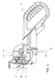
- Such a charging plug is in the Figures 1 and 2 shown.
- the charging plug 1 comprises an insertion region 2 for insertion into a corresponding bush, wherein the insertion region 2 has a recess 3 on the outside.
- the charging plug 1 can be locked in the socket by inserting a locking element formed on the socket into the recess 3 against being pulled out.
- the charging plug 1 is inserted in the direction of arrow 4, which represents the insertion direction in the socket.
- the invention is therefore an object of the invention to provide a charging plug of the type mentioned above, a stable Locking in the socket allows reliable insulation of the charging connector provides and ensures safe handling.
- a charging connector in particular for electric vehicles, is provided with an insertion region for insertion into a corresponding socket, the insertion region having a recess on the outside, and the charging connector in the socket can be locked against insertion by inserting a locking element formed on the socket into the recess is, wherein the insertion region is designed with a reinforcing element which reinforces the recess at its side facing in the insertion direction of the bushing side.
- the insertion region is reinforced with a reinforcing element in such a way that mechanical damage to the charging connector is prevented, even with high tensile forces.
- the reinforcing element is made of a harder material than the material of the insertion region. Due to the high strength of the material occurring locally by the locking element in the region of the recess occurring loads can be intercepted. The forces are introduced harmless in the insertion of the connector via the reinforcing element.
- the recess can be made in different ways, for example as a blind hole or groove.
- the insertion region is preferably made of an insulating material, for example an insulating plastic, so that the charging connector as a whole has good insulating properties.
- the charging plug is designed such that the reinforcing element is exchangeably fixed thereto.
- the charging plug can be further used.
- the reinforcing element is designed as a metal element.
- the reinforcing element may e.g. be designed as a sheet metal part of suitable material thickness or as a metal casting.
- the local arrangement in the region of the recess ensures good insulation properties of the charging plug.
- a suitable metal has a higher strength than the insertion area.
- the reinforcing element is designed as a punching element.
- the reinforcing element can be made low.
- the punching element is stamped from sheet metal.
- the reinforcing element has a substantially planar flat region, which is arranged on the outside on the insertion region.
- the insertion region is preferably designed with a depression for receiving the flat region.
- the charging plug is designed such that the reinforcing element has a flat transition with the insertion region.
- the flat area has a material thickness of not more than 3 mm. This material thickness allows the reinforcing element to be designed with a high degree of stability in order to absorb occurring forces and to introduce them into the insertion region.
- the insertion region on the outside a plurality of recesses, and the reinforcing element is designed to reinforce the recesses on their side facing in the insertion direction of the socket side.
- reinforcement of a plurality of recesses is effected in common, and the attachment of the reinforcing member can be easily and effectively achieved.
- the reinforcing element is designed such that it has the connecting webs between the recesses. The webs cause forces introduced into the reinforcing element to be distributed over an enlarged area of the lead-in area.
- the reinforcing element has an insertion region which is arranged on a side of the recess facing in the insertion direction of the bushing.
- the insertion region thus forms a reinforcement of the recess at its facing in the insertion direction of the socket front inner surface, so that forces can be reliably absorbed and distributed by the locking element.
- the reinforcing element is designed as a sheet metal element, and the insertion region is formed by bending over part of the sheet metal element.
- the recess is made in the reinforcing element.
- the entire recess is formed in the reinforcing member so that the reinforcing member can receive and distribute forces in any direction.
- the reinforcing element is designed with at least one lateral retaining lug which extends in the direction transverse to the insertion direction.
- the retaining lug securely holds the reinforcing element in the insertion area, and forces introduced into the reinforcing element can be distributed over an enlarged area of the insertion area.
- the dimensioning of the retaining lug is such that it has an extension in a direction transverse to the insertion direction.
- the retaining lug extends on the surface of the insertion area.
- the retaining lug may extend in a radial direction in the insertion region.
- two retaining lugs are formed in pairs on side edges of the reinforcing element.
- the reinforcing element is arranged in a region of the insertion region, which has a maximum distance from electrical contacts.
- the maximum distance can be determined in different ways known per se, wherein preferably an average value is formed for all contacts.
- the reinforcing element corresponding to the one contact has a maximum distance. Maximizing the distance ensures the greatest possible safety of the charging plug.
- the charging plug has a plurality of electrical contacts for the transmission of different currents and / or voltages, and the reinforcing element is arranged in a region of the lead-in area, which is a maximum distance from the electrical contacts for transmitting the largest voltages and / or currents having.
- the maximum distance can be determined in different ways known per se, wherein preferably an average value is formed for all contacts.
- the reinforcing element corresponding to the one contact has a maximum distance. Maximizing the distance ensures the greatest possible safety of the charging plug.
- the insulating property of the lead-in area can be maintained despite the substitution of an insulating material, for example a plastic, by an electrical conductor.
- the Figures 3 and 4 show a charging plug 10 according to the invention according to a first embodiment for connection to a corresponding socket 11, the in Fig. 3 is shown.
- the charging plug 10 is a charging plug for electric vehicles according to the standard IEC 62169-2.
- the charging connector 10 comprises an insertion region 12 for insertion into the bushing 11.
- the insertion region 12 is made of an insulating material, which in this exemplary embodiment is an insulating plastic.
- a reinforcing element 13 is attached to the insertion area 12.
- the reinforcing element 13 is designed as a metal casting with a higher strength than the plastic of the insertion region 12 and interchangeably attached to the insertion region 12.
- the reinforcing element 13 has a flat flat region 15, which is arranged on the outside of the insertion region 12.
- the insertion region 12 is designed with a recess 16 for receiving the reinforcing element 13, wherein the reinforcing element 13 forms a planar transition with the insertion region 12.
- the flat region 15 has a material thickness of less than 3 mm.
- the reinforcing element 13 is embodied on its flat region 15 with four retaining lugs 17, which are arranged in pairs on side edges of the flat region 15.
- the retaining lugs 17 extend in the direction transverse to a plug-in direction 19 of the charging plug 10 into the socket 11 on the surface of the insertion region 12.
- the charging plug 10 is, as in Fig. 3 is shown in the socket 11 by inserting a formed on the sleeve 11 locking element 20 in the recess 14 against withdrawal locked.
- the charging plug 10 has a plurality of electrical contacts 21 for transmitting different currents.
- the contacts 21 are designed for the transmission of alternating currents.
- the reinforcing element 13 is disposed in a region of the insertion region 12, the electric Contacts 21 has a maximum distance. In particular, the distance is at a maximum to the electrical contacts 21 for transmitting the largest currents of the charging plug 10.
- the charging plug 10 of the first embodiment a further known in the art lateral recess 3. Accordingly, the charging plug 10 in the socket 11 by inserting a further formed on the socket 11 locking element 20 in the lateral recess 3 additionally against withdrawal can be locked.
- a further reinforcing element 13 is formed on the insertion region 12, in which a recess 14 is formed as described above.
- FIGS. 5 and 6 relate to a charging plug 10 according to a second embodiment.
- the charging plug 10 of the second embodiment is largely identical to that of the first embodiment, for which reason the differences are discussed below.
- the charging plug 10 of the second embodiment also includes an insertion region 12 for insertion into the bush 11.
- a recess 14 is formed as a blind hole.
- a reinforcing element 13 is attached to the insertion region 12 in the region of the recess 14, which is produced as a punching element from a metal sheet with a material thickness of less than 3 mm. Accordingly, the entire reinforcing element 13 is designed as a flat flat area 15.
- the reinforcing element 13 is arranged on the outside of the insertion region 12.
- a passage opening 22 is formed, which corresponds to the recess 14 and reinforces the recess 14 at its side facing in the insertion direction 19 of the bushing 11 side.
- the insertion region 12 is designed with a recess 16 for receiving the reinforcing element 13, wherein the reinforcing element 13 forms a planar transition with the insertion region 12.
- the recess 16 is arranged around the recess 14.
- the metal of the reinforcing member 13 has higher strength than the material of the insertion portion 12.
- the reinforcing element 13 is designed with four retaining lugs 17, which are arranged in pairs on its side edges and extend in the direction transverse to the insertion direction 19 on the surface of the insertion region 12.
- charging plug 10 of the second embodiment is the same as that of the first embodiment.
- FIGS. 7 and 8th relate to a charging plug 10 according to a third embodiment.
- the charging plug 10 of the third embodiment is largely identical to that of the second embodiment, for which reason, in particular, the differences between the charging plug 10 of the second and third embodiments will be discussed below.
- the charging plug 10 of the third embodiment is designed as a combo plug that supports DC and AC charge. Accordingly, the Plug as described above contacts 21 for the AC charge and additional contacts 23 for the DC charge on.
- the charging plug 10 of the third embodiment also includes an insertion portion 12 for insertion into the socket 11.
- a plurality of recesses 14 are formed, which are formed as through holes through the insertion portion 12.
- a reinforcing element 13 is attached to the insertion region 12, which is produced as a punching element from a metal sheet with a material thickness of less than 3 mm. Accordingly, the entire reinforcing element 13 is designed as a flat flat area 15.
- the reinforcing member 13 has a bulge in accordance with a curvature of the insertion portion 12 on which it is disposed on the outside.
- a plurality of passage openings 22 are formed, which correspond to the recesses 14 and reinforce the recesses 14 on their side facing in the insertion direction 19 of the bushing 11 side.
- the reinforcing element 13 is designed in one piece, wherein the regions of the through openings 22 are connected by webs 24.
- the insertion region 12 is designed with a recess 16 for receiving the reinforcing element 13, wherein the reinforcing element 13 forms a planar transition with the insertion region 12.
- the recess 16 extends around the recesses 14 and between the recesses 14, so that the webs 24 are receivable therein, as in Fig. 7 is shown.
- the metal of the reinforcing member 13 has higher strength than the material of the insertion portion 12.
Landscapes
- Electric Propulsion And Braking For Vehicles (AREA)
- Connector Housings Or Holding Contact Members (AREA)
Abstract
Description
- Die vorliegende Erfindung betrifft einen Ladestecker, insbesondere für Elektrofahrzeuge, mit einem Einführbereich zum Einführen in eine korrespondierende Buchse, wobei der Einführbereich außenseitig eine Aussparung aufweist, und der Ladestecker in der Buchse durch das Einführen eines an der Buchse ausgebildeten Verriegelungselements in die Aussparung gegen Herausziehen verriegelbar ist.
- Derartige Ladestecker werden beispielsweise in der Fahrzeugtechnik verwendet, um Fahrzeuge mit elektrischen Antrieben mit einer elektrischen Energiequelle zu verbinden. Ein solcher Ladestecker ist beispielsweise ein Steckverbinder nach IEC 62169-2. Der Ladestecker kann mittels einer elektromechanischen Vorrichtung mit einem Verriegelungselement in einer korrespondierenden Buchse im gesteckten Zustand verriegelt werden. Die Vorrichtung befindet sich in der Regel an einem Gehäuse der Buchse, und umfasst ein Verriegelungselement, beispielsweise einen Bolzen, und einen Antrieb, der den Bolzen senkrecht zur Einsteckrichtung in die Buchse in eine Aussparung des Ladesteckers führt. Die Aussparung ist in einem Einführbereich des Ladesteckers ausgeführt, der im verbundenen Zustand in der Buchse aufgenommen ist.
- Hierdurch wird ein Formschluss des Ladesteckers in der Buchse in axialer Richtung, d.h. in Einsteckrichtung, erzeugt, wodurch ein unbeabsichtigtes oder auch ein nicht autorisiertes Trennen der elektrischen Verbindung zwischen dem Ladestecker und der Buchse verhindert wird.
- Im Fall des Ladesteckers gemäß IEC 62169-2 befindet sich auf der Oberseite des Ladesteckers eine normativ definierte Kontur in Form einer rechteckigen Aussparung, in welche der Bolzen radial einführbar ist. Die Aussparung ist in dem Einführbereich ausgebildet, und weist eine Dimension von ca. 6 x 4 mm bei einer Tiefe von weniger als 3 mm auf. Der Einführbereich bildet üblicherweise einen Isolierkörper des Ladesteckers, und ist daher aufgrund der gewünschten isolierenden Eigenschaften im Stand der Technik aus Kunststoff gefertigt.
- Ein solcher Ladestecker ist in den
Figuren 1 und 2 gezeigt. Der Ladestecker 1 umfasst einen Einführbereich 2 zum Einführen in eine korrespondierende Buchse, wobei der Einführbereich 2 außenseitig eine Aussparung 3 aufweist. Der Ladestecker 1 ist in der Buchse durch das Einführen eines an der Buchse ausgebildeten Verriegelungselements in die Aussparung 3 gegen Herausziehen verriegelbar. Der Ladestecker 1 wird in Richtung des Pfeils 4, der die Einsteckrichtung darstellt, in die Buchse eingeführt. - Wird im verriegelten Zustand versucht, den Ladestecker aus der Buchse zu ziehen, so treten zwischen der Aussparung und dem Verriegelungselement erhebliche mechanische Belastungen im Sinne von Flächenpressungen, Biege- und Scherspannungen auf, die in
Fig. 2 durch die Kraft F dargestellt sind. Dies führt zu einer Belastung des Ladesteckers im Einführbereich, insbesondere an einer in Einsteckrichtung der Buchse zugewandten Frontinnenfläche der Aussparung. Dabei kann die zulässige Spannung am Einführbereich überschritten werden, was zu einer unzulässigen Verformung oder schlimmstenfalls sogar zum Bruch des Bauteiles führt. - Ausgehend von dem oben genannten Stand der Technik liegt der Erfindung somit die Aufgabe zugrunde, einen Ladestecker der oben genannten Art anzugeben, der eine stabile Verriegelung in der Buchse ermöglicht, eine zuverlässige Isolierung des Ladesteckers bietet und eine sichere Handhabung gewährleistet.
- Die Lösung der Aufgabe erfolgt erfindungsgemäß durch die Merkmale des unabhängigen Anspruchs. Vorteilhafte Ausgestaltungen der Erfindung sind in den Unteransprüchen angegeben.
- Erfindungsgemäß ist somit ein Ladestecker, insbesondere für Elektrofahrzeuge, mit einem Einführbereich zum Einführen in eine korrespondierende Buchse vorgesehen, wobei der Einführbereich außenseitig eine Aussparung aufweist, und der Ladestecker in der Buchse durch das Einführen eines an der Buchse ausgebildeten Verriegelungselements in die Aussparung gegen Herausziehen verriegelbar ist, wobei der Einführbereich mit einem Verstärkungselement ausgeführt ist, das die Aussparung an ihrer in Einsteckrichtung der Buchse zugewandten Seite verstärkt.
- Grundidee der vorliegenden Erfindung ist es also, dass der Einführbereich derart mit einem Verstärkungselement verstärkt wird, dass eine mechanische Beschädigung des Ladesteckers auch bei großen Zugkräften verhindert wird. Entsprechend ist das Verstärkungselement aus einem härteren Material als das Material der Einführbereichs ausgeführt. Aufgrund der hohen Festigkeit des Werkstoffes können lokal durch das Verriegelungselement im Bereich der Aussparung auftretende Belastungen abgefangen werden. Die Kräfte werden über das Verstärkungselement unschädlich in den Einführbereich des Steckverbinders eingeleitet.
- Die Aussparung kann auf unterschiedliche Weise, beispielsweise als Sackloch oder Nut, ausgeführt sein. Vorzugsweise ist der Einführbereich aus einem Isolierstoff, beispielsweise einem isolierenden Kunststoff ausgeführt, so dass der Ladestecker insgesamt gute Isolationseigenschaften aufweist.
- Vorzugsweise ist der Ladestecker derart ausgeführt, dass das Verstärkungselement austauschbar daran befestigt ist. Somit kann bei einer Beschädigung durch den Austausch lediglich des Verstärkungselements der Ladestecker weiter verwendet werden.
- In vorteilhafter Ausgestaltung der Erfindung ist das Verstärkungselement als Metallelement ausgeführt. Das Verstärkungselement kann z.B. als ein Blechteil geeigneter Materialstärke oder als Metallgussteil ausgeführt sein. Durch die lokale Anordnung im Bereich der Aussparung werden gute Isolationseigenschaften des Ladesteckers gewährleistet. Ein geeignetes Metall hat eine höhere Festigkeit als der Einführbereich.
- In vorteilhafter Ausgestaltung der Erfindung ist das Verstärkungselement als Stanzelement ausgeführt. Damit kann das Verstärkungselement günstig hergestellt werden. Vorzugsweise ist das Stanzelement aus Metallblech gestanzt.
- In vorteilhafter Ausgestaltung der Erfindung weist das Verstärkungselement einen im Wesentlichen ebenen Flachbereich auf, der außenseitig an dem Einführbereich angeordnet ist. Vorzugsweise ist der Einführbereich mit einer Vertiefung zur Aufnahme des Flachbereichs ausgeführt. Weiter bevorzugt ist der Ladestecker derart ausgeführt, dass das Verstärkungselement mit dem Einführbereich einen ebenen Übergang aufweist.
- In vorteilhafter Ausgestaltung der Erfindung weist der Flachbereich eine Materialdicke von nicht mehr als 3 mm auf. Diese Materialdicke ermöglicht die Ausführung des Verstärkungselements mit einer hohen Stabilität, um auftretende Kräfte aufzunehmen und in den Einführbereich einzuleiten.
- In vorteilhafter Ausgestaltung der Erfindung weist der Einführbereich außenseitig eine Mehrzahl Aussparungen auf, und das Verstärkungselement ist ausgeführt, die Aussparungen an ihrer in Einsteckrichtung der Buchse zugewandten Seite zu verstärken. Somit wird mit einem einzelnen Verstärkungselement eine Verstärkung von mehreren Aussparungen gemeinsam bewirkt, wobei die Anbringung des Verstärkungselements einfach und effektiv erreicht werden kann. Vorzugsweise ist das Verstärkungselement derart ausgeführt, dass es zwischen den Aussparungen den Verbindungsstegen aufweist. Die Stege bewirken, dass in das Verstärkungselement eingeleitete Kräfte auf einen vergrößerten Bereich des Einführbereichs verteilt werden.
- In vorteilhafter Ausgestaltung der Erfindung weist das Verstärkungselement einen Einsetzbereich auf, der an einer in Einsteckrichtung der Buchse zugewandten Seite der Aussparung angeordnet ist. Der Einsetzbereich bildet somit eine Verstärkung der Aussparung an ihrer in Einsteckrichtung der Buchse zugewandten Frontinnenfläche, so dass Kräfte von dem Verriegelungselement zuverlässig aufgenommen und verteilt werden können. Vorzugsweise ist das Verstärkungselement als Blechelement ausgeführt, und der Einsetzbereich ist durch das Umbiegen eines Teils des Blechelements gebildet.
- In vorteilhafter Ausgestaltung der Erfindung ist die Aussparung in dem Verstärkungselement ausgeführt. Somit ist die gesamte Aussparung in dem Verstärkungselement ausgebildet, so dass das Verstärkungselement Kräfte in jeder Richtung aufnehmen und verteilen kann.
- In vorteilhafter Ausgestaltung der Erfindung ist das Verstärkungselement mit wenigstens einer seitlichen Haltenase ausgeführt, die sich in Richtung quer zu der Einsteckrichtung erstreckt. Durch die Haltenase wird das Verstärkungselement sicher in dem Einführbereich gehalten, und in das Verstärkungselement eingeleitete Kräfte können auf einen vergrößerten Bereich des Einführbereichs verteilt werden. Die Dimensionierung der Haltenase ist derart, dass sie eine Ausdehnung in einer Richtung quer zur Einsteckrichtung aufweist. Vorzugsweise erstreckt sich die Haltenase an der Oberfläche des Einführbereichs. Alternativ oder zusätzlich kann sich die Haltenase in einer radialen Richtung in den Einführbereich erstrecken. Besonders bevorzugt sind zwei Haltenasen paarweise an Seitenkanten des Verstärkungselements ausgebildet.
- In vorteilhafter Ausgestaltung der Erfindung ist das Verstärkungselement in einem Bereich des Einführbereichs angeordnet, der von elektrischen Kontakten einen maximalen Abstand aufweist. Der maximale Abstand kann auf unterschiedliche, an sich bekannte Weise bestimmt werden, wobei vorzugsweise ein Mittelwert für alle Kontakte gebildet wird. Bei einer Ausgestaltung des Ladesteckers mit nur einem Kontakt weist das Verstärkungselement entsprechend von dem einen Kontakt einen maximalen Abstand auf. Durch die Maximierung des Abstands wird eine größtmögliche Sicherheit des Ladesteckers gewährleistet.
- In vorteilhafter Ausgestaltung der Erfindung weist der Ladestecker eine Mehrzahl elektrische Kontakte zur Übertragung unterschiedlicher Ströme und/oder Spannungen auf, und das Verstärkungselement ist in einem Bereich des Einführbereichs angeordnet, der von den elektrischen Kontakten zur Übertragung der größten Spannungen und/oder Ströme einen maximalen Abstand aufweist. Der maximale Abstand kann auf unterschiedliche, an sich bekannte Weise bestimmt werden, wobei vorzugsweise ein Mittelwert für alle Kontakte gebildet wird. Bei einer Ausgestaltung des Ladesteckers mit nur einem Kontakt weist das Verstärkungselement entsprechend von dem einen Kontakt einen maximalen Abstand auf. Durch die Maximierung des Abstands wird eine größtmögliche Sicherheit des Ladesteckers gewährleistet.
- Somit kann bei einem elektrisch leitenden Verstärkungselement die isolierende Eigenschaft des Einführbereichs trotz der Substitution eines Isolierstoffs, beispielsweise eines Kunststoffs, durch einen elektrischen Leiter gewahrt bleiben.
- Nachfolgend wird die Erfindung unter Bezugnahme auf die anliegende Zeichnung anhand bevorzugter Ausführungsformen näher erläutert.
- Es zeigen
- Fig. 1
- eine perspektivische Ansicht eines Ladesteckers gemäß dem Stand der Technik,
- Fig. 2
- eine Detailansicht des Ladesteckers aus
Fig. 1 im Bereich seiner Aussparung in einer Draufsicht und einer Seitenansicht, - Fig. 3
- eine Seitenansicht eines Ladesteckers gemäß einer ersten Ausführungsform der Erfindung im mit einer Buchse verbundenen Zustand mit einem Ausbruch im Bereich des Verriegelungselements,
- Fig. 4
- eine perspektivische Explosionsansicht des Ladesteckers aus
Fig. 3 , - Fig. 5
- eine perspektivische Explosionsansicht eines Ladesteckers gemäß einer zweiten Ausführungsform der Erfindung,
- Fig. 6
- eine perspektivische Ansicht des Ladesteckers aus
Fig. 5 mit einer korrespondierenden Buchse, - Fig. 7
- eine perspektivische Ansicht eines Ladesteckers gemäß einer dritten Ausführungsform der Erfindung, und
- Fig. 8
- eine perspektivische Explosionsansicht des Ladesteckers aus
Fig. 7 . - Die
Figuren 3 und4 zeigen einen erfindungsgemäßen Ladestecker 10 gemäß einer ersten Ausführungsform zur Verbindung mit einer korrespondierenden Buchse 11, die inFig. 3 dargestellt ist. Der Ladestecker 10 ist ein Ladestecker für Elektrofahrzeuge gemäß der Norm IEC 62169-2. - Der Ladestecker 10 umfasst einen Einführbereich 12 zum Einführen in die Buchse 11. Der Einführbereich 12 ist aus einem Isolierstoff ausgeführt, der in diesem Ausführungsbeispiel ein isolierender Kunststoff ist. Außenseitig ist an dem Einführbereich 12 ein Verstärkungselement 13 angebracht. Das Verstärkungselement 13 ist als Metallgussteil mit einer höheren Festigkeit als der Kunststoff des Einführbereichs 12 ausgeführt und austauschbar an dem Einführbereich 12 befestigt.
- In dem Verstärkungselement 13 ist eine Aussparung 14 ausgebildet. Weiterhin weist das Verstärkungselement 13 einen ebenen Flachbereich 15 auf, der außenseitig an dem Einführbereich 12 angeordnet ist. Der Einführbereich 12 ist mit einer Vertiefung 16 zur Aufnahme des Verstärkungselements 13 ausgeführt, wobei das Verstärkungselement 13 mit dem Einführbereich 12 einen ebenen Übergang bildet. Der Flachbereich 15 weist eine Materialdicke von weniger als 3 mm auf.
- Das Verstärkungselement 13 ist an seinem Flachbereich 15 mit vier Haltenasen 17 ausgeführt, die paarweise an Seitenkanten des Flachbereichs 15 angeordnet sind. Die Haltenasen 17 erstrecken sich in Richtung quer zu einer Einsteckrichtung 19 des Ladesteckers 10 in die Buchse 11 an der Oberfläche des Einführbereichs 12.
- Der Ladestecker 10 ist, wie in
Fig. 3 gezeigt ist, in der Buchse 11 durch das Einführen eines an der Buchse 11 ausgebildeten Verriegelungselements 20 in die Aussparung 14 gegen Herausziehen verriegelbar. - Der Ladestecker 10 weist eine Mehrzahl elektrische Kontakte 21 zur Übertragung unterschiedlicher Ströme auf. In diesem Ausführungsbeispiel sind die Kontakte 21 zur Übertragung von Wechselströmen ausgeführt. Wie in den
Figuren 3 und4 gezeigt ist das Verstärkungselement 13 in einem Bereich des Einführbereichs 12 angeordnet, der von elektrischen Kontakten 21 einen maximalen Abstand aufweist. Insbesondere ist der Abstand maximal zu den elektrischen Kontakten 21 zur Übertragung der größten Ströme des Ladesteckers 10. - Wie in
Fig. 4 erkennbar ist, weist der Ladestecker 10 der ersten Ausführungsform eine weitere im Stand der Technik bekannte seitliche Aussparung 3 auf. Entsprechend ist der Ladestecker 10 in der Buchse 11 durch das Einführen eines weiteren an der Buchse 11 ausgebildeten Verriegelungselements 20 in die seitliche Aussparung 3 zusätzlich gegen Herausziehen verriegelbar. - In einer alternativen Ausführungsform ist ein weiteres Verstärkungselement 13 an dem Einführbereich 12 ausgebildet, in dem eine Aussparung 14 wie zuvor beschrieben ausgebildet ist.
-
Figuren 5 und6 betreffen einen Ladestecker 10 gemäß einer zweiten Ausführungsform. Der Ladestecker 10 der zweiten Ausführungsform ist weitgehend identisch zu dem der ersten Ausführungsform, weshalb im Weiteren auf die Unterschiede eingegangen wird. - Der Ladestecker 10 der zweiten Ausführungsform umfasst ebenfalls einen Einführbereich 12 zum Einführen in die Buchse 11. In dem Einführbereich 12 ist eine Aussparung 14 als Sackloch ausgebildet.
- Außenseitig ist an dem Einführbereich 12 im Bereich der Aussparung 14 ein Verstärkungselement 13 angebracht, das als Stanzelement aus einem Metallblech mit einer Materialdicke von weniger als 3 mm hergestellt ist. Entsprechend ist das ganze Verstärkungselement 13 als ebener Flachbereich 15 ausgeführt. Das Verstärkungselement 13 ist außenseitig an dem Einführbereich 12 angeordnet. In dem Verstärkungselement 13 ist eine Durchgangsöffnung 22 ausgebildet, die mit der Aussparung 14 korrespondiert und die Aussparung 14 an ihrer in Einsteckrichtung 19 der Buchse 11 zugewandten Seite verstärkt.
- Der Einführbereich 12 ist mit einer Vertiefung 16 zur Aufnahme des Verstärkungselements 13 ausgeführt, wobei das Verstärkungselement 13 mit dem Einführbereich 12 einen ebenen Übergang bildet. Die Vertiefung 16 ist um die Aussparung 14 angeordnet.
- Auch gemäß der zweiten Ausführungsform hat das Metall des Verstärkungselements 13 eine höhere Festigkeit als das Material des Einführbereichs 12.
- Das Verstärkungselement 13 ist mit vier Haltenasen 17 ausgeführt, die paarweise an seinen Seitenkanten angeordnet sind und sich in Richtung quer zu der Einsteckrichtung 19 an der Oberfläche des Einführbereichs 12 erstrecken.
- Im Übrigen stimmt Ladestecker 10 der zweiten Ausführungsform mit dem der ersten Ausführungsform überein.
- Die
Figuren 7 und8 betreffen einen Ladestecker 10 gemäß einer dritten Ausführungsform. Der Ladestecker 10 der dritten Ausführungsform ist in weiten Teilen identisch zu dem der zweiten Ausführungsform, weshalb nachstehend insbesondere auf die Unterschiede der Ladestecker 10 der zweiten und dritten Ausführungsform eingegangen wird. - Der Ladestecker 10 der dritten Ausführungsform ist als Combo-Stecker ausgeführt, der Gleich- und Wechselstromladung unterstützt. Entsprechend weist der Stecker wie zuvor beschrieben Kontakte 21 für die Wechselstromladung und zusätzliche Kontakte 23 für die Gleichstromladung auf.
- Der Ladestecker 10 der dritten Ausführungsform umfasst ebenfalls einen Einführbereich 12 zum Einführen in die Buchse 11. In dem Einführbereich 12 ist eine Mehrzahl Aussparungen 14 ausgebildet, die als Durchgangslöcher durch den Einführbereich 12 ausgeführt sind.
- Außenseitig ist an dem Einführbereich 12 ein Verstärkungselement 13 angebracht, das als Stanzelement aus einem Metallblech mit einer Materialdicke von weniger als 3 mm hergestellt ist. Entsprechend ist das ganze Verstärkungselement 13 als ebener Flachbereich 15 ausgeführt. Das Verstärkungselement 13 weist eine Wölbung in Übereinstimmung mit einer Wölbung des Einführbereichs 12 auf, an dem es außenseitig angeordnet ist. In dem Verstärkungselement 13 ist eine Mehrzahl Durchgangsöffnungen 22 ausgebildet, die mit den Aussparungen 14 korrespondieren und die Aussparungen 14 an ihrer in Einsteckrichtung 19 der Buchse 11 zugewandten Seite verstärken.
- Das Verstärkungselement 13 ist einteilig ausgeführt, wobei die Bereiche der Durchgangsöffnungen 22 durch Stege 24 verbunden sind. Der Einführbereich 12 ist mit einer Vertiefung 16 zur Aufnahme des Verstärkungselements 13 ausgeführt, wobei das Verstärkungselement 13 mit dem Einführbereich 12 einen ebenen Übergang bildet. Die Vertiefung 16 erstreckt sich um die Aussparungen 14 und zwischen den Aussparungen 14, so dass auch die Stege 24 darin aufnehmbar sind, wie in
Fig. 7 gezeigt ist. - Auch gemäß der dritten Ausführungsform hat das Metall des Verstärkungselements 13 eine höhere Festigkeit als das Material des Einführbereichs 12.
Bezugszeichenliste Ladestecker (Stand der Technik) 1 Einführbereich (Stand der Technik) 2 Aussparung (Stand der Technik) 3 Einsteckrichtung (Stand der Technik) 4 Kraft F Ladestecker 10 Buchse 11 Einführbereich 12 Verstärkungselement 13 Aussparung 14 Flachbereich 15 Vertiefung 16 Haltenase 17 Einsteckrichtung 19 Verriegelungselement 20 Kontakt (Wechselstromladung) 21 Durchgangsöffnung 22 Kontakt (Gleichstromladung) 23 Steg 24
Claims (10)
- Ladestecker (10), insbesondere für Elektrofahrzeuge, mit einem Einführbereich (12) zum Einführen in eine korrespondierende Buchse (11), wobei
der Einführbereich (12) außenseitig eine Aussparung (14) aufweist, und
der Ladestecker (10) in der Buchse (11) durch das Einführen eines an der Buchse (11) ausgebildeten Verriegelungselements (20) in die Aussparung (14) gegen Herausziehen verriegelbar ist,
dadurch gekennzeichnet, dass
der Einführbereich (12) mit einem Verstärkungselement (13) ausgeführt ist, das die Aussparung (14) an ihrer in Einsteckrichtung (19) der Buchse (11) zugewandten Seite verstärkt. - Ladestecker (10) nach Anspruch 1,
dadurch gekennzeichnet, dass
das Verstärkungselement (13) als Metallelement ausgeführt ist. - Ladestecker (10) nach einem der Ansprüche 1 oder 2,
dadurch gekennzeichnet, dass
das Verstärkungselement (13) als Stanzelement ausgeführt ist. - Ladestecker (10) nach einem der vorhergehenden Ansprüche,
dadurch gekennzeichnet, dass
das Verstärkungselement (13) einen im Wesentlichen ebenen Flachbereich (15) aufweist, der außenseitig an dem Einführbereich (12) angeordnet ist. - Ladestecker (10) nach einem der vorhergehenden Ansprüche,
dadurch gekennzeichnet, dass
der Einführbereich (12) außenseitig eine Mehrzahl Aussparungen (14) aufweist, und
das Verstärkungselement (13) ausgeführt ist, die Aussparungen (14) an ihrer in Einsteckrichtung (19) der Buchse (11) zugewandten Seite zu verstärken. - Ladestecker (10) nach einem der vorhergehenden Ansprüche,
dadurch gekennzeichnet, dass
das Verstärkungselement (13) einen Einsetzbereich aufweist, der an einer in Einsteckrichtung (19) der Buchse (11) zugewandten Seite der Aussparung (14) angeordnet ist. - Ladestecker (10) nach einem der vorhergehenden Ansprüche,
dadurch gekennzeichnet, dass
die Aussparung (14) in dem Verstärkungselement (13) ausgeführt ist. - Ladestecker (1) nach einem der vorhergehenden Ansprüche,
dadurch gekennzeichnet, dass
das Verstärkungselement (13) mit wenigstens einer seitlichen Haltenase (17) ausgeführt ist, die sich in Richtung quer zu der Einsteckrichtung (19) erstreckt. - Ladestecker (10) nach einem der vorhergehenden Ansprüche,
dadurch gekennzeichnet, dass
das Verstärkungselement (13) in einem Bereich des Einführbereichs (12) angeordnet ist, der von elektrischen Kontakten (21, 23) einen maximalen Abstand aufweist. - Ladestecker (10) nach einem der vorhergehenden Ansprüche,
dadurch gekennzeichnet, dass
der Ladestecker (10) eine Mehrzahl elektrische Kontakte (21, 23) zur Übertragung unterschiedlicher Ströme und/oder Spannungen aufweist, und
das Verstärkungselement (13) in einem Bereich des Einführbereichs (12) angeordnet ist, der von den elektrischen Kontakten (21, 23) zur Übertragung der größten Spannungen und/oder Ströme einen maximalen Abstand aufweist.
Applications Claiming Priority (1)
| Application Number | Priority Date | Filing Date | Title |
|---|---|---|---|
| DE102013102823.3A DE102013102823A1 (de) | 2013-03-19 | 2013-03-19 | Ladestecker mit Verstärkungselement |
Publications (2)
| Publication Number | Publication Date |
|---|---|
| EP2782194A1 true EP2782194A1 (de) | 2014-09-24 |
| EP2782194B1 EP2782194B1 (de) | 2019-05-01 |
Family
ID=50239496
Family Applications (1)
| Application Number | Title | Priority Date | Filing Date |
|---|---|---|---|
| EP14158778.2A Active EP2782194B1 (de) | 2013-03-19 | 2014-03-11 | Ladestecker mit Verstärkungselement |
Country Status (3)
| Country | Link |
|---|---|
| EP (1) | EP2782194B1 (de) |
| CN (1) | CN104064927B (de) |
| DE (1) | DE102013102823A1 (de) |
Families Citing this family (2)
| Publication number | Priority date | Publication date | Assignee | Title |
|---|---|---|---|---|
| DE102016105371A1 (de) | 2016-03-22 | 2017-09-28 | Phoenix Contact E-Mobility Gmbh | Steckverbinderteil zum steckenden Verbinden mit einem Gegensteckverbinderteil |
| FR3060875B1 (fr) | 2016-12-16 | 2026-03-13 | Delphi Int Operations Luxembourg Sarl | Enveloppe rigide de connecteur de cable electrique de vehicule |
Citations (4)
| Publication number | Priority date | Publication date | Assignee | Title |
|---|---|---|---|---|
| DE2107180A1 (de) * | 1970-02-16 | 1971-09-09 | Bunker Ramo | Zweiteiliger Verbinder und Feder band zur Verwendung in einem zweitei hgen Verbinder |
| EP1764879A1 (de) * | 2005-09-14 | 2007-03-21 | Sumitomo Wiring Systems, Ltd. | Verbinder, Verbinderanordnung und Montageverfahren |
| EP2352208A1 (de) * | 2008-11-21 | 2011-08-03 | Yazaki Corporation | Ladestecker |
| DE102010003523A1 (de) * | 2010-03-31 | 2011-10-06 | Kiekert Ag | Verriegelungseinrichtung für ein Kraftfahrzeug |
Family Cites Families (8)
| Publication number | Priority date | Publication date | Assignee | Title |
|---|---|---|---|---|
| US4305180A (en) * | 1979-12-14 | 1981-12-15 | International Telephone And Telegraph Corporation | Bayonet coupling nut |
| JPH0322865Y2 (de) * | 1985-04-04 | 1991-05-17 | ||
| JPH09161882A (ja) * | 1995-12-06 | 1997-06-20 | Yazaki Corp | 電気自動車の充電用コネクタ |
| DE29613694U1 (de) * | 1996-08-08 | 1997-12-18 | ITT Cannon GmbH, 71384 Weinstadt | Steckverbinder |
| JP4747753B2 (ja) * | 2005-09-14 | 2011-08-17 | 住友電装株式会社 | コネクタ |
| SG132555A1 (en) * | 2005-11-29 | 2007-06-28 | J S T Mfg Co Ltd | Female connector and male connector |
| JP5218114B2 (ja) * | 2009-02-03 | 2013-06-26 | トヨタ自動車株式会社 | 充電用コネクタ |
| DE102009039652A1 (de) * | 2009-09-02 | 2011-03-17 | Elektro-Bauelemente Gmbh | Vorrichtung und Verfahren zur Verriegelung eines Steckers in einer Steckdose |
-
2013
- 2013-03-19 DE DE102013102823.3A patent/DE102013102823A1/de not_active Ceased
-
2014
- 2014-03-11 EP EP14158778.2A patent/EP2782194B1/de active Active
- 2014-03-18 CN CN201410101608.3A patent/CN104064927B/zh not_active Expired - Fee Related
Patent Citations (4)
| Publication number | Priority date | Publication date | Assignee | Title |
|---|---|---|---|---|
| DE2107180A1 (de) * | 1970-02-16 | 1971-09-09 | Bunker Ramo | Zweiteiliger Verbinder und Feder band zur Verwendung in einem zweitei hgen Verbinder |
| EP1764879A1 (de) * | 2005-09-14 | 2007-03-21 | Sumitomo Wiring Systems, Ltd. | Verbinder, Verbinderanordnung und Montageverfahren |
| EP2352208A1 (de) * | 2008-11-21 | 2011-08-03 | Yazaki Corporation | Ladestecker |
| DE102010003523A1 (de) * | 2010-03-31 | 2011-10-06 | Kiekert Ag | Verriegelungseinrichtung für ein Kraftfahrzeug |
Also Published As
| Publication number | Publication date |
|---|---|
| CN104064927B (zh) | 2017-04-12 |
| EP2782194B1 (de) | 2019-05-01 |
| DE102013102823A1 (de) | 2014-09-25 |
| CN104064927A (zh) | 2014-09-24 |
Similar Documents
| Publication | Publication Date | Title |
|---|---|---|
| DE102007040937B3 (de) | Elektrischer Kontakt | |
| EP2690716B1 (de) | Elektrisches Anschlusselement | |
| EP2255412B1 (de) | Elektrische anschlusseinrichtung | |
| EP3058624B1 (de) | Steckverbinder mit verrastungssystem | |
| DE29516504U1 (de) | Elektrischer Steckverbinder mit hoher Dichte | |
| DE202009014251U1 (de) | System zur Verbindung elektrischer Leiter mit voneinander verschiedenen Potentialen sowie Steckadapter für das System | |
| WO2005046002A1 (de) | Flachsteckbuchse | |
| DE102015221937A1 (de) | Rastelement eines Kontaktes mit nasenförmigem Vorsprung | |
| EP3186858A1 (de) | Kontaktelement | |
| EP2439816B1 (de) | Elektrische Verbindungsklemme | |
| DE202013001487U1 (de) | Stoßstromoptimierte Federklemme | |
| EP2782194B1 (de) | Ladestecker mit Verstärkungselement | |
| DE102015111675A1 (de) | Steckverbinder und Verformungswerkzeug hierzu | |
| DE102011051951A1 (de) | Steckverbinder mit Zugentlastung | |
| DE102016206846B4 (de) | Verbindungseinrichtung, Hochvoltbatterie und Kraftfahrzeug | |
| EP0845160B1 (de) | Elektrischer verbinder | |
| EP2337161B1 (de) | Steckeranordnung und Abdichteinrichtung für wenigstens eine, insbesondere elektrische Leitung | |
| EP2856567B1 (de) | Kontakt mit widerstandsfähiger primärlanze zum verriegeln in einer kontaktkammer eines steckverbinders | |
| EP2698874B1 (de) | Kontaktsystem mit einem Einpresskontakt | |
| WO2013034443A1 (de) | Elektrischer verbinder mit berührschutz | |
| EP3123566B1 (de) | Kontaktbuchse für eine steckdose oder kupplung | |
| EP2230731A1 (de) | Elektrischer Steckverbinder | |
| DE102013221901A1 (de) | Demontagewerkzeug für elektrische Steckkontakte | |
| DE102018111628A1 (de) | Steckervorrichtung mit Lamellen und Verriegelungselement | |
| EP2759024A1 (de) | Steckelement |
Legal Events
| Date | Code | Title | Description |
|---|---|---|---|
| PUAI | Public reference made under article 153(3) epc to a published international application that has entered the european phase |
Free format text: ORIGINAL CODE: 0009012 |
|
| 17P | Request for examination filed |
Effective date: 20140311 |
|
| AK | Designated contracting states |
Kind code of ref document: A1 Designated state(s): AL AT BE BG CH CY CZ DE DK EE ES FI FR GB GR HR HU IE IS IT LI LT LU LV MC MK MT NL NO PL PT RO RS SE SI SK SM TR |
|
| AX | Request for extension of the european patent |
Extension state: BA ME |
|
| R17P | Request for examination filed (corrected) |
Effective date: 20150324 |
|
| RBV | Designated contracting states (corrected) |
Designated state(s): AL AT BE BG CH CY CZ DE DK EE ES FI FR GB GR HR HU IE IS IT LI LT LU LV MC MK MT NL NO PL PT RO RS SE SI SK SM TR |
|
| STAA | Information on the status of an ep patent application or granted ep patent |
Free format text: STATUS: EXAMINATION IS IN PROGRESS |
|
| 17Q | First examination report despatched |
Effective date: 20170315 |
|
| GRAP | Despatch of communication of intention to grant a patent |
Free format text: ORIGINAL CODE: EPIDOSNIGR1 |
|
| STAA | Information on the status of an ep patent application or granted ep patent |
Free format text: STATUS: GRANT OF PATENT IS INTENDED |
|
| INTG | Intention to grant announced |
Effective date: 20181030 |
|
| GRAS | Grant fee paid |
Free format text: ORIGINAL CODE: EPIDOSNIGR3 |
|
| GRAA | (expected) grant |
Free format text: ORIGINAL CODE: 0009210 |
|
| STAA | Information on the status of an ep patent application or granted ep patent |
Free format text: STATUS: THE PATENT HAS BEEN GRANTED |
|
| AK | Designated contracting states |
Kind code of ref document: B1 Designated state(s): AL AT BE BG CH CY CZ DE DK EE ES FI FR GB GR HR HU IE IS IT LI LT LU LV MC MK MT NL NO PL PT RO RS SE SI SK SM TR |
|
| REG | Reference to a national code |
Ref country code: GB Ref legal event code: FG4D Free format text: NOT ENGLISH |
|
| REG | Reference to a national code |
Ref country code: CH Ref legal event code: EP Ref country code: AT Ref legal event code: REF Ref document number: 1128174 Country of ref document: AT Kind code of ref document: T Effective date: 20190515 |
|
| REG | Reference to a national code |
Ref country code: DE Ref legal event code: R096 Ref document number: 502014011551 Country of ref document: DE |
|
| REG | Reference to a national code |
Ref country code: IE Ref legal event code: FG4D Free format text: LANGUAGE OF EP DOCUMENT: GERMAN |
|
| REG | Reference to a national code |
Ref country code: NL Ref legal event code: MP Effective date: 20190501 |
|
| REG | Reference to a national code |
Ref country code: LT Ref legal event code: MG4D |
|
| PG25 | Lapsed in a contracting state [announced via postgrant information from national office to epo] |
Ref country code: AL Free format text: LAPSE BECAUSE OF FAILURE TO SUBMIT A TRANSLATION OF THE DESCRIPTION OR TO PAY THE FEE WITHIN THE PRESCRIBED TIME-LIMIT Effective date: 20190501 Ref country code: ES Free format text: LAPSE BECAUSE OF FAILURE TO SUBMIT A TRANSLATION OF THE DESCRIPTION OR TO PAY THE FEE WITHIN THE PRESCRIBED TIME-LIMIT Effective date: 20190501 Ref country code: NL Free format text: LAPSE BECAUSE OF FAILURE TO SUBMIT A TRANSLATION OF THE DESCRIPTION OR TO PAY THE FEE WITHIN THE PRESCRIBED TIME-LIMIT Effective date: 20190501 Ref country code: FI Free format text: LAPSE BECAUSE OF FAILURE TO SUBMIT A TRANSLATION OF THE DESCRIPTION OR TO PAY THE FEE WITHIN THE PRESCRIBED TIME-LIMIT Effective date: 20190501 Ref country code: LT Free format text: LAPSE BECAUSE OF FAILURE TO SUBMIT A TRANSLATION OF THE DESCRIPTION OR TO PAY THE FEE WITHIN THE PRESCRIBED TIME-LIMIT Effective date: 20190501 Ref country code: HR Free format text: LAPSE BECAUSE OF FAILURE TO SUBMIT A TRANSLATION OF THE DESCRIPTION OR TO PAY THE FEE WITHIN THE PRESCRIBED TIME-LIMIT Effective date: 20190501 Ref country code: SE Free format text: LAPSE BECAUSE OF FAILURE TO SUBMIT A TRANSLATION OF THE DESCRIPTION OR TO PAY THE FEE WITHIN THE PRESCRIBED TIME-LIMIT Effective date: 20190501 Ref country code: NO Free format text: LAPSE BECAUSE OF FAILURE TO SUBMIT A TRANSLATION OF THE DESCRIPTION OR TO PAY THE FEE WITHIN THE PRESCRIBED TIME-LIMIT Effective date: 20190801 Ref country code: PT Free format text: LAPSE BECAUSE OF FAILURE TO SUBMIT A TRANSLATION OF THE DESCRIPTION OR TO PAY THE FEE WITHIN THE PRESCRIBED TIME-LIMIT Effective date: 20190901 |
|
| PG25 | Lapsed in a contracting state [announced via postgrant information from national office to epo] |
Ref country code: RS Free format text: LAPSE BECAUSE OF FAILURE TO SUBMIT A TRANSLATION OF THE DESCRIPTION OR TO PAY THE FEE WITHIN THE PRESCRIBED TIME-LIMIT Effective date: 20190501 Ref country code: LV Free format text: LAPSE BECAUSE OF FAILURE TO SUBMIT A TRANSLATION OF THE DESCRIPTION OR TO PAY THE FEE WITHIN THE PRESCRIBED TIME-LIMIT Effective date: 20190501 Ref country code: GR Free format text: LAPSE BECAUSE OF FAILURE TO SUBMIT A TRANSLATION OF THE DESCRIPTION OR TO PAY THE FEE WITHIN THE PRESCRIBED TIME-LIMIT Effective date: 20190802 Ref country code: BG Free format text: LAPSE BECAUSE OF FAILURE TO SUBMIT A TRANSLATION OF THE DESCRIPTION OR TO PAY THE FEE WITHIN THE PRESCRIBED TIME-LIMIT Effective date: 20190801 |
|
| PG25 | Lapsed in a contracting state [announced via postgrant information from national office to epo] |
Ref country code: IS Free format text: LAPSE BECAUSE OF FAILURE TO SUBMIT A TRANSLATION OF THE DESCRIPTION OR TO PAY THE FEE WITHIN THE PRESCRIBED TIME-LIMIT Effective date: 20190901 |
|
| PG25 | Lapsed in a contracting state [announced via postgrant information from national office to epo] |
Ref country code: CZ Free format text: LAPSE BECAUSE OF FAILURE TO SUBMIT A TRANSLATION OF THE DESCRIPTION OR TO PAY THE FEE WITHIN THE PRESCRIBED TIME-LIMIT Effective date: 20190501 Ref country code: SK Free format text: LAPSE BECAUSE OF FAILURE TO SUBMIT A TRANSLATION OF THE DESCRIPTION OR TO PAY THE FEE WITHIN THE PRESCRIBED TIME-LIMIT Effective date: 20190501 Ref country code: RO Free format text: LAPSE BECAUSE OF FAILURE TO SUBMIT A TRANSLATION OF THE DESCRIPTION OR TO PAY THE FEE WITHIN THE PRESCRIBED TIME-LIMIT Effective date: 20190501 Ref country code: EE Free format text: LAPSE BECAUSE OF FAILURE TO SUBMIT A TRANSLATION OF THE DESCRIPTION OR TO PAY THE FEE WITHIN THE PRESCRIBED TIME-LIMIT Effective date: 20190501 Ref country code: DK Free format text: LAPSE BECAUSE OF FAILURE TO SUBMIT A TRANSLATION OF THE DESCRIPTION OR TO PAY THE FEE WITHIN THE PRESCRIBED TIME-LIMIT Effective date: 20190501 |
|
| REG | Reference to a national code |
Ref country code: DE Ref legal event code: R097 Ref document number: 502014011551 Country of ref document: DE |
|
| PG25 | Lapsed in a contracting state [announced via postgrant information from national office to epo] |
Ref country code: SM Free format text: LAPSE BECAUSE OF FAILURE TO SUBMIT A TRANSLATION OF THE DESCRIPTION OR TO PAY THE FEE WITHIN THE PRESCRIBED TIME-LIMIT Effective date: 20190501 |
|
| PLBE | No opposition filed within time limit |
Free format text: ORIGINAL CODE: 0009261 |
|
| STAA | Information on the status of an ep patent application or granted ep patent |
Free format text: STATUS: NO OPPOSITION FILED WITHIN TIME LIMIT |
|
| PG25 | Lapsed in a contracting state [announced via postgrant information from national office to epo] |
Ref country code: TR Free format text: LAPSE BECAUSE OF FAILURE TO SUBMIT A TRANSLATION OF THE DESCRIPTION OR TO PAY THE FEE WITHIN THE PRESCRIBED TIME-LIMIT Effective date: 20190501 |
|
| 26N | No opposition filed |
Effective date: 20200204 |
|
| PG25 | Lapsed in a contracting state [announced via postgrant information from national office to epo] |
Ref country code: PL Free format text: LAPSE BECAUSE OF FAILURE TO SUBMIT A TRANSLATION OF THE DESCRIPTION OR TO PAY THE FEE WITHIN THE PRESCRIBED TIME-LIMIT Effective date: 20190501 |
|
| PGFP | Annual fee paid to national office [announced via postgrant information from national office to epo] |
Ref country code: IT Payment date: 20200324 Year of fee payment: 7 |
|
| PG25 | Lapsed in a contracting state [announced via postgrant information from national office to epo] |
Ref country code: SI Free format text: LAPSE BECAUSE OF FAILURE TO SUBMIT A TRANSLATION OF THE DESCRIPTION OR TO PAY THE FEE WITHIN THE PRESCRIBED TIME-LIMIT Effective date: 20190501 |
|
| PG25 | Lapsed in a contracting state [announced via postgrant information from national office to epo] |
Ref country code: MC Free format text: LAPSE BECAUSE OF FAILURE TO SUBMIT A TRANSLATION OF THE DESCRIPTION OR TO PAY THE FEE WITHIN THE PRESCRIBED TIME-LIMIT Effective date: 20190501 |
|
| REG | Reference to a national code |
Ref country code: CH Ref legal event code: PL |
|
| REG | Reference to a national code |
Ref country code: BE Ref legal event code: MM Effective date: 20200331 |
|
| PG25 | Lapsed in a contracting state [announced via postgrant information from national office to epo] |
Ref country code: LU Free format text: LAPSE BECAUSE OF NON-PAYMENT OF DUE FEES Effective date: 20200311 |
|
| PG25 | Lapsed in a contracting state [announced via postgrant information from national office to epo] |
Ref country code: FR Free format text: LAPSE BECAUSE OF NON-PAYMENT OF DUE FEES Effective date: 20200331 Ref country code: IE Free format text: LAPSE BECAUSE OF NON-PAYMENT OF DUE FEES Effective date: 20200311 Ref country code: CH Free format text: LAPSE BECAUSE OF NON-PAYMENT OF DUE FEES Effective date: 20200331 Ref country code: LI Free format text: LAPSE BECAUSE OF NON-PAYMENT OF DUE FEES Effective date: 20200331 |
|
| PG25 | Lapsed in a contracting state [announced via postgrant information from national office to epo] |
Ref country code: BE Free format text: LAPSE BECAUSE OF NON-PAYMENT OF DUE FEES Effective date: 20200331 |
|
| GBPC | Gb: european patent ceased through non-payment of renewal fee |
Effective date: 20200311 |
|
| PG25 | Lapsed in a contracting state [announced via postgrant information from national office to epo] |
Ref country code: GB Free format text: LAPSE BECAUSE OF NON-PAYMENT OF DUE FEES Effective date: 20200311 |
|
| REG | Reference to a national code |
Ref country code: AT Ref legal event code: MM01 Ref document number: 1128174 Country of ref document: AT Kind code of ref document: T Effective date: 20200311 |
|
| PG25 | Lapsed in a contracting state [announced via postgrant information from national office to epo] |
Ref country code: AT Free format text: LAPSE BECAUSE OF NON-PAYMENT OF DUE FEES Effective date: 20200311 |
|
| PG25 | Lapsed in a contracting state [announced via postgrant information from national office to epo] |
Ref country code: IT Free format text: LAPSE BECAUSE OF NON-PAYMENT OF DUE FEES Effective date: 20210311 |
|
| PG25 | Lapsed in a contracting state [announced via postgrant information from national office to epo] |
Ref country code: MT Free format text: LAPSE BECAUSE OF FAILURE TO SUBMIT A TRANSLATION OF THE DESCRIPTION OR TO PAY THE FEE WITHIN THE PRESCRIBED TIME-LIMIT Effective date: 20190501 Ref country code: CY Free format text: LAPSE BECAUSE OF FAILURE TO SUBMIT A TRANSLATION OF THE DESCRIPTION OR TO PAY THE FEE WITHIN THE PRESCRIBED TIME-LIMIT Effective date: 20190501 |
|
| PG25 | Lapsed in a contracting state [announced via postgrant information from national office to epo] |
Ref country code: MK Free format text: LAPSE BECAUSE OF FAILURE TO SUBMIT A TRANSLATION OF THE DESCRIPTION OR TO PAY THE FEE WITHIN THE PRESCRIBED TIME-LIMIT Effective date: 20190501 |
|
| P01 | Opt-out of the competence of the unified patent court (upc) registered |
Effective date: 20230424 |
|
| PGFP | Annual fee paid to national office [announced via postgrant information from national office to epo] |
Ref country code: DE Payment date: 20250528 Year of fee payment: 12 |