EP2781879A1 - Système de laser de construction constitué d'un laser rotatif et d'un récepteur laser, doté d'une fonctionnalité de détermination automatique de la direction du récepteur laser - Google Patents
Système de laser de construction constitué d'un laser rotatif et d'un récepteur laser, doté d'une fonctionnalité de détermination automatique de la direction du récepteur laser Download PDFInfo
- Publication number
- EP2781879A1 EP2781879A1 EP13160068.6A EP13160068A EP2781879A1 EP 2781879 A1 EP2781879 A1 EP 2781879A1 EP 13160068 A EP13160068 A EP 13160068A EP 2781879 A1 EP2781879 A1 EP 2781879A1
- Authority
- EP
- European Patent Office
- Prior art keywords
- laser
- laser beam
- rotation angle
- receiver
- respect
- Prior art date
- Legal status (The legal status is an assumption and is not a legal conclusion. Google has not performed a legal analysis and makes no representation as to the accuracy of the status listed.)
- Granted
Links
Images


Classifications
-
- G—PHYSICS
- G01—MEASURING; TESTING
- G01C—MEASURING DISTANCES, LEVELS OR BEARINGS; SURVEYING; NAVIGATION; GYROSCOPIC INSTRUMENTS; PHOTOGRAMMETRY OR VIDEOGRAMMETRY
- G01C15/00—Surveying instruments or accessories not provided for in groups G01C1/00 - G01C13/00
- G01C15/002—Active optical surveying means
- G01C15/004—Reference lines, planes or sectors
-
- G—PHYSICS
- G01—MEASURING; TESTING
- G01B—MEASURING LENGTH, THICKNESS OR SIMILAR LINEAR DIMENSIONS; MEASURING ANGLES; MEASURING AREAS; MEASURING IRREGULARITIES OF SURFACES OR CONTOURS
- G01B11/00—Measuring arrangements characterised by the use of optical techniques
- G01B11/26—Measuring arrangements characterised by the use of optical techniques for measuring angles or tapers; for testing the alignment of axes
-
- G—PHYSICS
- G01—MEASURING; TESTING
- G01B—MEASURING LENGTH, THICKNESS OR SIMILAR LINEAR DIMENSIONS; MEASURING ANGLES; MEASURING AREAS; MEASURING IRREGULARITIES OF SURFACES OR CONTOURS
- G01B11/00—Measuring arrangements characterised by the use of optical techniques
-
- G—PHYSICS
- G01—MEASURING; TESTING
- G01C—MEASURING DISTANCES, LEVELS OR BEARINGS; SURVEYING; NAVIGATION; GYROSCOPIC INSTRUMENTS; PHOTOGRAMMETRY OR VIDEOGRAMMETRY
- G01C9/00—Measuring inclination, e.g. by clinometers, by levels
- G01C9/02—Details
- G01C9/06—Electric or photoelectric indication or reading means
- G01C2009/066—Electric or photoelectric indication or reading means optical
Definitions
- the invention relates to a construction laser system for works in construction and / or interior design, of rotary laser and laser receiver, with respect to deployment effort and execution speed improved functionality for determining a direction in which the laser receiver from the viewpoint of the rotary laser is. Furthermore, the invention relates to a corresponding method with rotary laser and laser receiver, wherein in an improved manner, a determination of the direction in which the laser receiver is from the viewpoint of the rotary laser, takes place, and a computer program product for carrying out this method.
- rotary lasers are used in which a laser beam emitted by a laser unit (in the visible or infrared wavelength range) generates a reference surface by deflection via a rotating deflection prism, which then provides a precise plane reference (in particular a height reference in the case of a horizontal plane).
- beam self-leveling functionality also known as self-leveling
- Various technical solutions are known for the fulfillment of such a beam self-horizontalization functionality, which may be both of a purely mechanical nature but today are mostly based on sensors of an optical type.
- this may in particular be the laser unit and the rotatable deflection prism comprehensive core of the rotary laser (ie, the laser core module) be suspended pendulum, so that a Horizontriosstreue can be generated by utilizing gravity.
- the laser core module can advantageously be suspended about two axes (at least slightly in a range of, for example, + 5 °) precisely tiltable on an outer housing of the device and be equipped with a tilt sensor or horizontal sensor whose display or Signal can be read and used as an output variable for an active change of the inclination position of the laser core module.
- known rotary lasers today also have a function (with corresponding mechanics, sensors and control) for the targeted, desired inclination of the laser plane relative to the horizontal in one or two directions.
- the heart of the rotary laser in particular comprising the laser unit and the rotatable deflection prism, can be specifically motorized tilted about an axis or about two axes and brought into desired inclination positions so that the axis of rotation and thus also the plane spanned are desired.
- Corresponding mechanisms, sensors and controls therefor are well known in the art and eg in the patent literature publications US 5,485,266 A . US 2004/0125356 A1 .
- a reference line is visible there as the basis for further measures.
- Hand-held laser receivers also called laser receivers
- a wall or in the terrain which can determine and index a position with high precision relative to a reference surface spanned by the rotary laser.
- Hand-held laser receivers known from the prior art for determining a position relative to the reference surface may comprise a laser beam detector comprising a plurality of photosensitive elements, which is designed to generate an output signal upon impact of the laser beam on the laser beam detector.
- the laser beam detector is usually designed so that in addition an impact position of the laser beam on the laser beam detector surface can be derived, for which the photosensitive elements - viewed in upright operating position of the device - in a vertically aligned sensor line can be strung together such that the laser beam detector thus extends over at least a one-dimensional area on the laser receiver.
- an evaluation unit for determining the position of the laser receiver relative to the reference height defined by the rotating laser beam based on the output of the laser beam detector and an indicator for the determined position (such as a visual display), in particular designed for indicating whether the laser receiver with the Reference surface exactly coincident, integrated into the laser receiver device.
- the position can be determined, for example, on the basis of a ratio of a plurality of output signals (eg as a midpoint that part area on the laser beam detector line illuminated by the laser beam).
- Such hand-held laser receiver can be used in particular when the line imaged by the rotating laser beam with the eye is difficult or not precise enough recognizable. This is e.g. the case for example at longer distances from rotating laser (eg due to a divergence of the laser beam [-> imaged line becomes too wide] or a low light output [-> imaged line becomes too weak] (which is subject to certain limitations for eye safety reasons) and / or a high ambient brightness) or even when using laser light in the non-visible wavelength range.
- a height mark may be provided on the housing of the laser receiver at the level of the defined zero point (e.g., a notch or a printed line on the side of the housing).
- a laser receiver direction may be necessary or at least helpful (at least rough).
- Knowledge of a direction in which the laser receiver is from the viewpoint of the rotating laser e.g., a rotating laser-internal coordinate system.
- a supporting functionality can also be realized in such a way that a signal regarding the quality of the orientation of the tilt axis is made, for example by a display which supports the user-directed alignment of the laser core module (for example an indication of value) or left / right / center information).
- a display which supports the user-directed alignment of the laser core module (for example an indication of value) or left / right / center information).
- points 2) and 4) above are comparatively lengthy in their execution and require various different steps and / or decision making, so that thereby also a comparatively high susceptibility to errors. Furthermore, the method as described in point 2) only works with a receiver held upright (or a slanted holding of the receiver leads to a falsified result).
- the method as described under point 3) is very complex to implement, since an adhesion of the laser radiation with continuously varying information is required and also on the receiver side a specific detection of the incident laser beam (ie so that the adhering information is not lost) and evaluation for information purposes.
- a beam parameter of the laser radiation which is continuously varied as a function of the angle can lead to inaccuracies in the final angle determination during evaluation of a signal generated upon detection of the laser radiation (eg if a global shift of the parameter in its value, which is varied as a function of angle (for example due to Shock or obsolescence of the device)).
- the object of the invention is therefore to provide a design laser system of rotary laser and laser receiver which is improved in terms of functionality for determining a laser receiver direction.
- the functionality for determining a laser receiver direction should be more robust, faster, more reliable and / or less expensive for implementation in practice.
- the inventive design laser system comprises at least one rotating laser comprising a laser unit and a rotatable deflection means for emitting a rotating laser beam, the rotating laser beam defining a reference surface, and a laser receiver having a laser beam detector extending at least over a one-dimensional area on the laser receiver for generating an output signal depending on an impact of the laser beam on the laser beam detector.
- an evaluation unit is provided for determining a laser receiver direction in which the laser receiver is located from the perspective of the rotary laser.
- the invention solves this from the prior art by now to the determination of the laser receiver direction a rotation angle range-dependent digital multi-track code pattern is used, wherein the plurality of tracks are generated and imaged here by a series of multiple rotation passes, and in the respective rotation passage that of the associated track corresponding angle range pattern is generated by modification of the laser beam (such as switching on and off).
- a control unit is now provided for such deflection-synchronized control of the laser unit with respect to generation of the at least two different discrete states that in the respective rotation angle ranges corresponding to the respective rotation angle range sequence of states with respect to the laser beam - at the end of a series of rotational passages of the deflection - Successive traversals of the respective rotation angle range is generated.
- Evaluation unit side finally, an output signal sequence of successive incoming output signals are detected, a corresponding to the output signal sequence state value sequence identified from the stored state value sequences and the laser receiver direction are determined depending on the rotation angle range associated with the code corresponding to the identified state value sequence.
- the process according to the invention for determining the direction can be executed fully automatically, whereby this process can always be carried out strictly in accordance with a predefined scheme and thus constant and reliable with respect to the required time duration as well as with regard to the expected result (for example as regards the accuracy of the direction determination).
- each of the functional units of the system can perform its task according to a precisely predetermined scheme.
- each direction determination takes in principle exactly the same length and it provides reliable, robust and essentially independent of external influences, the particular direction with a constant and exactly systemally known maximum deviation error (even with aging of the device, etc.) ready.
- a real-time evaluation can actually be dispensed with in which the achievable result depends on how precise individual events can be brought into temporal relation to one another (see, for example, the method as described under point 1).
- a time-sensitive recording of respective "strikes" on the receiver is only required if at most and only with such temporal accuracy / correlation, as far as this is for the assignment of the output signals of the detected output signal sequence to the corresponding Rotation turns the series of predetermined rotation passes is needed.
- a temporal resolution of one-tenth of a second would be sufficient.
- a design laser system comprising a rotating laser and a laser receiver, which is improved in terms of functionality for determining a laser receiver direction, is thus provided. Furthermore, the functionality for determining a laser receiver direction can thus also be improved in noisy / disturbed environments, more robust, faster, more reliable and / or less complicated to implement in practice.
- the determination of the laser receiver direction can now also be done over long distances between laser receiver and rotary laser.
- the rotational angle ranges stored in the memory can be defined over a circumferential range of at least 180 ° with respect to the rotation of the deflection means. In particular, however, they can be varied over the full extent of rotation, i. over a circumferential range of 360 ° with respect to the rotation of the deflection, to be defined.
- rotational angle ranges e.g. be defined at least 30, in particular at least 100, in particular at least 500, rotational angle ranges over the peripheral region.
- a corresponding number of code tracks or length of the state value sequence (and thus also a corresponding number of rotation passes and thereby traversing the respective rotation angle ranges ) required.
- At least seven code tracks are required for the realization of 100 rotational angle ranges, since this is the smallest power of two covering the number 100 (ie power to Base 2) corresponds.
- the rotational angle ranges can each be equidistant and equally distributed and be defined directly adjacent to one another over the circumferential region.
- the codes stored in the memory can be defined in such a way that adjacent pairs of state value sequences of codes, which are respectively assigned to directly adjacent rotation angle ranges, differ by only one value at a time.
- the definition or assignment of the codes to the respective rotation angle ranges can also take place randomly or according to another special assignment pattern, wherein it is essential that an unambiguous assignment (and thus an unambiguous derivability of a corresponding rotation angle range from an identified code) is ensured (absolute coding ).
- the number of code tracks required depends on the desired angular resolution or number of rotational angle ranges to be covered / provided in the code, depending on the intended amount of distinguishable states of the laser beam.
- the codes stored in the memory are defined, for example, such that the state value sequences each comprise a state value sequence number of links of at least five state values (i.e., the code has at least five tracks).
- control unit can then in the simple case then depending on the intended number of code tracks for Such control of the laser unit may be configured such that the respective sequences of states are generated at a number of rotational passes corresponding to the state value sequence number of links (ie code track number).
- the code track number is equal to the number of revolutions of the series of revolutions through which the code is imaged with the laser beam, in other words, in this example, the respective sequences of states are generated in a series of revolutions which is equal to the state value sequence number of links (that is, the code track number).
- each state of a given state value sequence may also be e.g. exactly two times in a row with two turns of rotation (or in each case two successive traverses of the rotation angle range) are generated and ultimately evaluated the detected output signal sequence in knowledge of this fact (eg, only every second output signal can be considered or redundancy for the Evaluation are produced).
- rotation number of turns of the series of rotation passes generated over the respective sequence of states with respect to the laser beam would be twice as large as the state value sequence number of links (that is, the code track number).
- the codes and angle ranges can be defined depending on the situation and requirements in each case depending on the case, for example, depending on the time available for a Measurement and according to the need for precision and depending on the need for reliability a corresponding code pattern (ie the need optimally covering opaque opaque number of areas and the needs optimized as possible opaque opaque number of code tracks (ie state values per code) and the needs optimized as possible opaque
- a corresponding code pattern ie the need optimally covering opaque opaque number of areas and the needs optimized as possible opaque opaque number of code tracks (ie state values per code) and the needs optimized as possible opaque
- the number of turns of rotation over which the code pattern is generated is used.
- An inventive advantage of the situation-dependent freely configurable and in particular reconfigurable code is that it can be adapted according to need, the direction measurement in terms of speed or accuracy, without having to make hardware modifications.
- five different codes can be pre-stored, each optimized for different needs, and by a user or an application, the most appropriate for the current case coding are selected so that the direction determination is executable in different modes (a speed mode, an accuracy mode, a compromise mode, etc.).
- the code used according to the invention is to be referred to as digital code, ie there is no continuous variation of one Beam parameters, but are used discrete, abruptly differing and clearly divergent states with respect to the laser beam.
- two laser beams of different wavelengths can be used (either from two alternately or superimposing on and off laser sources emitting in clearly distinguishable colors, or from a tunable laser diode emitting alternately at different wavelengths).
- the laser beam can be emitted with two clearly distinguishable discrete modulation frequencies, etc.
- the advantage of the use of discrete, discontinuous and clearly distinguishable states is the independence from a distance from the laser receiver to the rotating laser, and that even with aging or otherwise caused absolute shift of the / n for the generation of the discrete states varied laser beam / s these after how to identify each other clearly distinguishable from each other (eg, based on knowledge that a certain state is provided with a clear higher value of a laser beam parameter than some other state, so by detection side / Auswertschem comparison of the signals with each other - despite absolute value shift with respect to this parameter - the States can still be provided and detected on the side of the detection / can be differentiated and unambiguously identifiable, and thus ultimately the quality of the result of the direction determination remains unaffected t).
- the evaluation unit and / or the laser receiver are designed to evaluate the output signals detected in the output signal sequence with regard to the at least two defined different discrete states and to adhere the output signals with corresponding information (in particular if the output signal itself does not inherently make the respective state derivable or makes itself inherently informable about it).
- the evaluation unit can then be designed to identify the corresponding state value sequence using the information pertaining to the respective output signals. If information relating to the at least two defined different discrete states adheres to the respective output signals directly on the basis of production (i.e., when generated by the laser receiver via its laser beam detector), the evaluation unit can identify the corresponding state value sequence directly using the information directly adhering to the respective output signals.
- the laser receiver can be designed to generate the output signals with information regarding a time of incidence of the laser beam on the Laser beam detector (eg signals can be generated, each of which embody a time-stamped "strike") or, for example, each passing time periods between each other following "Strikes" as signals to be embodied).
- the evaluation unit can also receive the respective transmitted output signals with information regarding a reception time, so that information about in which of the rotational passages of the series of rotation passes in the rotation angle range where the laser receiver is the laser beam was respectively switched on and off can be obtained therefrom can.
- the evaluation unit can identify the state value sequence corresponding to the detected output signal sequence by using the time information which is attached to the output signals.
- the evaluation unit uses the knowledge of the stored defined rotation angle ranges and the stored codes associated therewith for detecting the output signal sequence, for identifying the state value sequence and for determining the laser receiver direction from in each case one state value sequence (ie Evaluation unit uses the stored information).
- the detection of the output signal sequence, the identification of the state value sequence and the determination of the laser receiver direction are based on the information stored in the memory (such as the defined rotation angle ranges and the codes associated therewith).
- the code itself may also be defined and selected so that it can be determined from the state value sequence itself that the code now begins or has begun (for example, in that each code in the first track has a uniformly specified state).
- an end of the code e.g. otherwise predetermined to be detectable on the basis of the known code track number or in turn based on the fact that each code in the last track has a uniformly specially defined state.
- An assignment of output signals of the output signal sequence to respective rotational passages of the series (or to respective state values of the state value sequence of the codes) can also take place on the basis of a sequence member sequence or sequence member number / position.
- a specific direction in particular the direction corresponding to the respective rotation angle range halving, can be stored in the memory for the respective rotation angle ranges.
- the evaluation unit may then retrieve the appropriate direction (i.e., the direction deposited for the rotation angle range corresponding to the identified code) and set that retrieved direction as the laser receiver direction.
- another concrete direction may also be deposited from the rotation angle range (e.g., the direction corresponding to the left or right rotation angle range boundary, etc.), which is then determined and output as the laser receiver direction.
- the rotation angle range e.g., the direction corresponding to the left or right rotation angle range boundary, etc.
- in particular means for making available continuous angular information with respect to a respectively current rotational position of the deflection means can be present on the part of the rotation laser.
- the location or location where the evaluation unit is physically accommodated within the scope of the system according to the invention may be chosen differently depending on the requirements / requirements and on the desired design, e.g. in the rotating laser, in the receiver or in a third physical component (such as in a processing and control unit on a machine), or even distributed over several physical units such as e.g. proportionately distributed over the receiver and the rotating laser, wherein in the receiver, a first part of the evaluation (such as a preprocessing) and in the rotation laser, the further processing and eventual direction determination from the preprocessed data.
- a first part of the evaluation such as a preprocessing
- the rotation laser the further processing and eventual direction determination from the preprocessed data.
- various types of communication means with corresponding communication interfaces can also be provided, which are used to transmit the output signal to the evaluation unit or, if the evaluation unit is physically distributed over several units, to transfer data between the parts Serve evaluation unit.
- communication means with corresponding communication interfaces can also be provided, which are used to transmit the output signal to the evaluation unit or, if the evaluation unit is physically distributed over several units, to transfer data between the parts Serve evaluation unit.
- radio links or other wireless or wired data links may be used as well known in the art.
- the invention also relates to a rotary laser for use as part in the design laser system described above.
- the rotary laser is suitably equipped with at least one laser unit and a continuously rotatable deflection means for emitting a rotating laser beam such that the rotating laser beam defines a reference surface.
- the rotation laser has a control unit for controlling the laser unit synchronously with the deflection means so as to produce the at least two different discrete states such that in the respective rotation angle ranges the respective sequence of states with respect to the laser beam corresponds to the respective rotation angle range at the end of a series of rotation passes of the deflection means - successive traversing of the respective rotation angle range is generated.
- the invention also relates to a laser receiver for use as part of the design laser system described above.
- a conditional value sequence that is based on a defined sequence of states with respect to the laser beam, the states originating from a set of at least two defined different discrete states with respect to the laser beam.
- the computer program product contains such a program code that it is designed to carry out the method described above, in particular when the program is executed on an electronic data processing unit, in particular wherein the electronic data processing unit as a control and evaluation unit of the design laser system described above, as control and If necessary, evaluation unit of the above-described rotary laser or as an evaluation unit of the laser receiver described above is used.
- FIG. 1 shows an embodiment of a construction laser system according to the invention with a laser unit 11 and a rotatable deflection means 12 having rotating laser 10 for emitting a rotating laser beam 14, wherein the rotating laser beam defines a reference surface, and a laser receiver 20 with at least one via a one-dimensional area on the laser receiver extending laser beam detector 21, which is designed to generate an output signal 24 depending on an impact of the laser beam on the laser beam detector.
- an evaluation unit 16 is provided for determining a laser receiver direction in which the laser receiver 20 is located from the perspective of the rotary laser 10.
- a control unit 18 is now provided for such deflection-synchronized control of the laser unit 11 with respect to generation of the at least two different discrete states, that in the respective rotation angle ranges corresponding to the respective rotation angle range of states with respect to the laser beam 14 - at the end of a series of Turning passages of the deflecting means 12 - successive crossings of the respective rotation angle range is generated.
- an output signal sequence of successively arriving output signals 24 can be detected, a state value sequence corresponding to the output signal sequence can be identified from the stored state value sequences, and the laser receiver direction can be determined depending on the rotation angle range associated with the code corresponding to the identified state value sequence ,
- kabbellose communication means with a rotation laser side, at least data-receiving communication interface 19 and a laser receiver side, at least data transmitting communication interface 29 (in particular each wireless modules) may be provided for transmission of the Output signal 24 to the evaluation unit 19 serve.
- the laser receiver direction determination is thus made possible in a simple manner, without the need for a predefined and modularity veruniquede hardware tuning of various components of the two interacting devices to each other (eg, in terms of wavelength or modulation mode of the laser beam with appropriate hardware-side design of the transmitter-side laser source or ., the receiver-side laser beam detector) and without that for a dedicated special training of the laser receiver is absolutely necessary (and the functionality thus Laser receiver device execution may be independent).
- a laser receiver direction determination can also be carried out in parallel for two or more laser receivers.
- the laser radiation emitted by the laser unit 11 strikes in its beam path a laser radiation deflecting unit 12 which deflects the laser beam by 90 ° in the example shown.
- the laser beam deflection unit 12 is designed, for example, as a mirror tilted by 45 ° to the incident laser radiation, but preferably as a pentaprism or pentagonal mirror, which always deflects the laser radiation by 90 ° independently of the angle of incidence.
- the laser beam deflection unit 12 is in such a winking connection with a rotation movement unit, so that the laser radiation deflection unit 12 rotates about a rotation axis 13 so that it can be driven by a motor.
- the rotation unit is formed, for example, as a ball-bearing, the beam path of the laser radiation surrounding sleeve, which is driven by a belt drive by an electric motor.
- the emission of a laser radiation 14 takes place in a rotating emission direction ⁇ , so that the illustrated quasi-laser plane is generated.
- the center of rotation the intersection of this quasi-laser plane with the axis of rotation 13 is defined.
- the rotation center can be surrounded by a transparent exit window such that the laser radiation passes through the exit window to the outside.
- On the rotation unit 3 Mstoff can indirectly For example, be arranged in the form of an angle detector, which allow detection of the respective current angular orientation of the Laserstrahlungsumschnica 12 (ie an angle information with respect to a respective current rotational position of the deflecting means 12) and thus the respective emission direction ⁇ of the laser radiation 5.
- the laser beam detector 21 of the Laserreceivers 20 can also - as known from the prior art - be designed so that in addition an impact position of the laser beam on the laser beam detector line or surface can be derived, for which the photosensitive elements - considered in the upright operating position of the device - can be strung together in a vertically aligned sensor line, so that the laser beam detector 21 extends at least over a vertical line (as a one-dimensional area) on the laser receiver 20.
- the laser receiver 20 can also have its own evaluation unit for determining the position of the laser receiver relative to the reference height defined by the rotating laser beam on the basis of the output of the laser beam detector 20 and an indicator for the determined position (for example a visual display), in particular designed for indication whether the laser receiver 20 coincides exactly with the reference surface, be integrated into the laser receiver device.
- the position may be e.g. as the center of that area on the laser beam detector line which is illuminated by the laser beam.
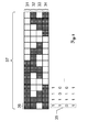
- FIG. 2 shows an illustration for explaining the inventive rotation angle range-dependent digital multi-track absolute coding.
- the plurality of tracks are formed and imaged by a series of plural rotation passes 31-34, thereby generating, in the respective rotation passage, the angular pattern corresponding to the corresponding track by modification of the laser beam (such as turn on and off).
- the respective rotation angle ranges 36 are each uniquely assigned a digital code 35 from a four-state state value sequence (which corresponds to four code tracks), which is based on a defined sequence of states with respect to the laser beam, wherein the states comprise a set of two different discrete states originate from the laser beam (eg a switched-on laser beam [white in the sample or shown unfilled] and a switched-off laser beam [shown in dark hatching]).
- the rotation angle ranges 36 are defined here via the figurative rolled-out or plane-shaped circumferential region 38 with respect to a rotation of the deflection means.
- 16 unique codes can be generated (two up 4). Each of the 16 defined angle ranges is uniquely assigned to one of the 16 codes.
- the codes are defined such that neighbor pairs of state value sequences of the codes respectively associated with directly adjacent rotation angle ranges differ in only one member (i.e., one state value at a time).
- the rotation angle ranges are each equidistant and equally distributed and defined directly adjacent to each other over the peripheral region 38.
- a signal can now be generated and sent to the evaluation unit for each incidence of the laser beam (ie per "strike").
- the corresponding rotation angle range in which the receiver must be well derived the desired laser receiver direction can be determined.
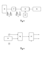
- FIG. 3 Fig. 11 is an illustration for explaining an example of the structure of the control for the laser unit (ie, an illustration for exemplifying the laser pattern encoder principle).
- the laser beam 14 emitted by the laser unit and exiting through the pentaprism may be controlled by a laser driver 43 (which is part of the control unit).
- the rotary encoder 42 provides information about the current angular position of the pentaprism.
- the codes are stored in the look-up table 45.
- This look-up table 45 now generates an ON / OFF signal for the laser driver 43 depending on the aforementioned signals from the state machine 44.
- the ON / OFF state with respect to the laser beam can be defined individually for the respective angular ranges and respective turning passes after application of the trigger signal B.
- FIG. 4 shows an illustration of which function the laser receiver can take purely by way of example in the context of the design laser system.
- the laser receiver is designed to measure the time t0 between two consecutive "strikes" by the laser beam on the laser beam detector 46, for which purpose the raw output signal of the laser beam detector 46 is passed through a trigger 47 and a counting circuit 48.
- the time t0 is communicated to the rotating laser via the in-vehicle radio module 50, as a multiple of a basic time unit (e.g., 1 ms).
- FIG. 5 shows an illustration for explaining an example of the structure of the evaluation unit (ie, an illustration for exemplifying the laser pattern decoder principle).
- the sequence of symbols thus created for a rotation angle range is independent of the rotation time of the deflection means.
- the decoder 53 converts the sequence of symbols into a valid, corresponding code number (which is assigned to the angular range in which the laser receiver is therefore located).
- the transmission time for the radio communication may be unknown, since the laser pattern encoding can be done independently and if necessary asynchronously from the decoding of the searched direction.
- the laser receiver does not require any prior knowledge of the codes used.
Priority Applications (3)
| Application Number | Priority Date | Filing Date | Title |
|---|---|---|---|
| EP13160068.6A EP2781879B1 (fr) | 2013-03-19 | 2013-03-19 | Système de laser de construction constitué d'un laser rotatif et d'un récepteur laser, doté d'une fonctionnalité de détermination automatique de la direction du récepteur laser |
| US14/218,700 US9175956B2 (en) | 2013-03-19 | 2014-03-18 | Construction laser system having a rotation laser and a laser receiver, with functionality for automatic determination of the laser receiver direction |
| CN201410102474.7A CN104061911B (zh) | 2013-03-19 | 2014-03-19 | 包括旋转激光器和激光接收器的建筑激光系统 |
Applications Claiming Priority (1)
| Application Number | Priority Date | Filing Date | Title |
|---|---|---|---|
| EP13160068.6A EP2781879B1 (fr) | 2013-03-19 | 2013-03-19 | Système de laser de construction constitué d'un laser rotatif et d'un récepteur laser, doté d'une fonctionnalité de détermination automatique de la direction du récepteur laser |
Publications (2)
| Publication Number | Publication Date |
|---|---|
| EP2781879A1 true EP2781879A1 (fr) | 2014-09-24 |
| EP2781879B1 EP2781879B1 (fr) | 2015-09-30 |
Family
ID=47913128
Family Applications (1)
| Application Number | Title | Priority Date | Filing Date |
|---|---|---|---|
| EP13160068.6A Active EP2781879B1 (fr) | 2013-03-19 | 2013-03-19 | Système de laser de construction constitué d'un laser rotatif et d'un récepteur laser, doté d'une fonctionnalité de détermination automatique de la direction du récepteur laser |
Country Status (3)
| Country | Link |
|---|---|
| US (1) | US9175956B2 (fr) |
| EP (1) | EP2781879B1 (fr) |
| CN (1) | CN104061911B (fr) |
Cited By (2)
| Publication number | Priority date | Publication date | Assignee | Title |
|---|---|---|---|---|
| US9200900B2 (en) | 2013-03-19 | 2015-12-01 | Leica Geosystems Ag | Construction laser system with an at least partially automatically running recalibration functionality for a beam levelling functionality |
| US10066935B2 (en) | 2015-01-21 | 2018-09-04 | Trimble Kaiserslautern Gmbh | Laser device and laser beam detector for detecting light of a laser device |
Families Citing this family (18)
| Publication number | Priority date | Publication date | Assignee | Title |
|---|---|---|---|---|
| EP2557392A1 (fr) * | 2011-08-11 | 2013-02-13 | Leica Geosystems AG | Dispositif de mesure et procédé doté d'une fonctionnalité de ciblage échelonnable et basée sur l'orientation d'une unité de télécommande |
| CN104197904B (zh) * | 2014-09-26 | 2016-07-06 | 中车成都机车车辆有限公司 | 一种铁道客车车体钢结构框架快速定位划线法 |
| EP3118577B1 (fr) * | 2015-07-17 | 2019-06-26 | Leica Geosystems AG | Dispositif et procédé d'étalonnage pour dispositif de test de l'exactitude d'un faisceau laser |
| EP3173741A1 (fr) * | 2015-11-30 | 2017-05-31 | HILTI Aktiengesellschaft | Procede de controle et/ou d'etalonnage d'un axe horizontal d'un laser rotatif |
| EP3173739A1 (fr) * | 2015-11-30 | 2017-05-31 | HILTI Aktiengesellschaft | Procede de controle et/ou d'etalonnage d'un axe vertical d'un laser rotatif |
| DE102016107100A1 (de) * | 2016-04-18 | 2017-10-19 | Status Pro Maschinenmesstechnik Gmbh | Rotationslaser für die Vermessung von Werkzeugmaschinen |
| DE102016107101A1 (de) * | 2016-04-18 | 2017-10-19 | Status Pro Maschinenmesstechnik Gmbh | Rotationslaser |
| EP3264040A1 (fr) * | 2016-06-30 | 2018-01-03 | HILTI Aktiengesellschaft | Procede de comparaison d'un faisceau de reception se produisant sur un recepteur laser avec un faisceau laser rotatif |
| CN107138864B (zh) * | 2017-07-07 | 2023-06-09 | 东宁晟(北京)数字科技有限公司 | 激光数控点桩仪 |
| CN109387826B (zh) * | 2017-08-04 | 2024-03-19 | 美国西北仪器公司 | 测量角度、距离的方法、绘制轨迹图方法及激光测距系统 |
| CN108919186A (zh) * | 2018-02-08 | 2018-11-30 | 深圳市海司恩科技有限公司 | 紫外光源定位方法、紫外光源定位装置及存储介质 |
| CN109015336B (zh) * | 2018-10-26 | 2023-09-29 | 飞磁电子材料(东莞)有限公司 | 一种t型铁氧体磁芯的研磨面平行度检测系统及方法 |
| DE102019218270A1 (de) * | 2018-12-11 | 2020-06-18 | Aktiebolaget Skf | Ein System und Verfahren zum Bestimmen einer Winkelverschiebung, -geschwindigkeit und -beschleunigung eines rotierenden Elements, das an einer Plattform befestigt ist |
| US11852725B2 (en) * | 2019-02-08 | 2023-12-26 | Topcon Positioning Systems, Inc. | System and method for determining an elevation of a laser detector |
| JP2022012497A (ja) * | 2020-07-01 | 2022-01-17 | 株式会社マキタ | レーザー墨出し器システム、携帯端末装置、及びレーザー光受光位置報知プログラム |
| CN116391107A (zh) | 2020-12-01 | 2023-07-04 | 米沃奇电动工具公司 | 激光水平仪接口和控制件 |
| CN112815929B (zh) * | 2020-12-31 | 2022-03-29 | 美国西北仪器公司 | 使用激光扫平仪追踪探测器的方法及激光追踪系统 |
| CN113639674B (zh) * | 2021-10-13 | 2022-01-14 | 成都宏明电子股份有限公司 | 基于光折射原理的非接触式旋转电位器 |
Citations (16)
| Publication number | Priority date | Publication date | Assignee | Title |
|---|---|---|---|---|
| US4240208A (en) | 1979-10-01 | 1980-12-23 | John V. Pehrson | Hand-held laser surveying rod |
| US5485266A (en) | 1992-07-09 | 1996-01-16 | Kabushiki Kaisha Topcon | Laser beam survey instrument having a tiltable laser beam axis and tilt detectors |
| US5953108A (en) | 1997-05-28 | 1999-09-14 | Laser Alignment, Inc. | Laser beam projector power and communication system |
| US6055046A (en) | 1999-02-01 | 2000-04-25 | Spectra Precision, Inc. | System and method for aligning a laser transmitter |
| US6314650B1 (en) | 1999-02-11 | 2001-11-13 | Laser Alignment, Inc. | Laser system for generating a reference plane |
| EP1174682A2 (fr) * | 2000-07-19 | 2002-01-23 | Kabushiki Kaisha TOPCON | Système de détermination de position |
| US6693706B2 (en) | 2002-01-08 | 2004-02-17 | Trimble Navigation Limited | Laser reference system and method of determining grade rake |
| US20040125356A1 (en) | 2001-03-29 | 2004-07-01 | Michael Connolly | Laser lavelling apparatus |
| WO2006070009A2 (fr) | 2004-12-28 | 2006-07-06 | Leica Geosystems Ag | Procede et laser rotatif pour determiner une information de position d'au moins un objet |
| EP1790940A2 (fr) | 2005-11-08 | 2007-05-30 | Kabushiki Kaisha Topcon | Instrument de surveillance laser |
| EP1901034A2 (fr) | 2006-09-13 | 2008-03-19 | Kabushiki Kaisha TOPCON | Dispositif d'inclinaison de l'axe optique d'un système optique laser |
| US7394527B2 (en) | 2000-08-01 | 2008-07-01 | Androtec Gmbh | Measuring device and measuring method for determining distance and/or position |
| EP2199739A1 (fr) | 2008-12-17 | 2010-06-23 | Leica Geosystems AG | Récepteur laser pour la détection d'une position relative |
| EP2327958A1 (fr) | 2009-11-26 | 2011-06-01 | Leica Geosystems AG | Laser de construction rotatif doté d'un mécanisme de double graduation |
| EP2453204A1 (fr) * | 2010-11-10 | 2012-05-16 | Leica Geosystems AG | Système de construction à laser et procédé |
| EP2522954A1 (fr) | 2011-05-11 | 2012-11-14 | Leica Geosystems AG | Laser de construction rotatif inclinable doté d'un mécanisme de graduation et procédé pour déterminer une position d'un bras de graduation du mécanisme de graduation |
Family Cites Families (11)
| Publication number | Priority date | Publication date | Assignee | Title |
|---|---|---|---|---|
| US7287336B1 (en) * | 2000-10-04 | 2007-10-30 | Trimble Navigation Limited | Apparatus for producing a visible line of light on a surface, particularly a wall |
| JP4354343B2 (ja) * | 2004-06-15 | 2009-10-28 | 株式会社トプコン | 位置測定システム |
| JP2010139477A (ja) * | 2008-12-15 | 2010-06-24 | Ihi Corp | センサの取付構造 |
| JP5439684B2 (ja) * | 2009-07-17 | 2014-03-12 | オプテックス株式会社 | レーザスキャンセンサ |
| EP2453205A1 (fr) * | 2010-11-11 | 2012-05-16 | Leica Geosystems AG | Dispositif de mesure et de construction pour mesurer et marquer des points spatiaux le long de courbes de niveau se déroulant horizontalement sur une surface |
| EP2458328B1 (fr) * | 2010-11-24 | 2016-01-27 | Leica Geosystems AG | Dispositif de mesure et de construction doté d'une fonctionnalité de recherche de point d'aplomb automatique |
| CN202101649U (zh) * | 2011-06-23 | 2012-01-04 | 重庆交通大学 | 二维微小扭转角测量系统 |
| EP2557392A1 (fr) * | 2011-08-11 | 2013-02-13 | Leica Geosystems AG | Dispositif de mesure et procédé doté d'une fonctionnalité de ciblage échelonnable et basée sur l'orientation d'une unité de télécommande |
| EP2639548A1 (fr) * | 2012-03-15 | 2013-09-18 | Leica Geosystems AG | Récepteur laser capable de détecter ses propres mouvements |
| EP2789973B1 (fr) * | 2013-04-12 | 2017-11-22 | Hexagon Technology Center GmbH | Laser à rotation avec lentille pouvant être déformée intentionnellement par des actionneurs |
| JP6253973B2 (ja) * | 2013-12-27 | 2017-12-27 | 株式会社トプコン | 測量装置 |
-
2013
- 2013-03-19 EP EP13160068.6A patent/EP2781879B1/fr active Active
-
2014
- 2014-03-18 US US14/218,700 patent/US9175956B2/en active Active
- 2014-03-19 CN CN201410102474.7A patent/CN104061911B/zh active Active
Patent Citations (16)
| Publication number | Priority date | Publication date | Assignee | Title |
|---|---|---|---|---|
| US4240208A (en) | 1979-10-01 | 1980-12-23 | John V. Pehrson | Hand-held laser surveying rod |
| US5485266A (en) | 1992-07-09 | 1996-01-16 | Kabushiki Kaisha Topcon | Laser beam survey instrument having a tiltable laser beam axis and tilt detectors |
| US5953108A (en) | 1997-05-28 | 1999-09-14 | Laser Alignment, Inc. | Laser beam projector power and communication system |
| US6055046A (en) | 1999-02-01 | 2000-04-25 | Spectra Precision, Inc. | System and method for aligning a laser transmitter |
| US6314650B1 (en) | 1999-02-11 | 2001-11-13 | Laser Alignment, Inc. | Laser system for generating a reference plane |
| EP1174682A2 (fr) * | 2000-07-19 | 2002-01-23 | Kabushiki Kaisha TOPCON | Système de détermination de position |
| US7394527B2 (en) | 2000-08-01 | 2008-07-01 | Androtec Gmbh | Measuring device and measuring method for determining distance and/or position |
| US20040125356A1 (en) | 2001-03-29 | 2004-07-01 | Michael Connolly | Laser lavelling apparatus |
| US6693706B2 (en) | 2002-01-08 | 2004-02-17 | Trimble Navigation Limited | Laser reference system and method of determining grade rake |
| WO2006070009A2 (fr) | 2004-12-28 | 2006-07-06 | Leica Geosystems Ag | Procede et laser rotatif pour determiner une information de position d'au moins un objet |
| EP1790940A2 (fr) | 2005-11-08 | 2007-05-30 | Kabushiki Kaisha Topcon | Instrument de surveillance laser |
| EP1901034A2 (fr) | 2006-09-13 | 2008-03-19 | Kabushiki Kaisha TOPCON | Dispositif d'inclinaison de l'axe optique d'un système optique laser |
| EP2199739A1 (fr) | 2008-12-17 | 2010-06-23 | Leica Geosystems AG | Récepteur laser pour la détection d'une position relative |
| EP2327958A1 (fr) | 2009-11-26 | 2011-06-01 | Leica Geosystems AG | Laser de construction rotatif doté d'un mécanisme de double graduation |
| EP2453204A1 (fr) * | 2010-11-10 | 2012-05-16 | Leica Geosystems AG | Système de construction à laser et procédé |
| EP2522954A1 (fr) | 2011-05-11 | 2012-11-14 | Leica Geosystems AG | Laser de construction rotatif inclinable doté d'un mécanisme de graduation et procédé pour déterminer une position d'un bras de graduation du mécanisme de graduation |
Cited By (2)
| Publication number | Priority date | Publication date | Assignee | Title |
|---|---|---|---|---|
| US9200900B2 (en) | 2013-03-19 | 2015-12-01 | Leica Geosystems Ag | Construction laser system with an at least partially automatically running recalibration functionality for a beam levelling functionality |
| US10066935B2 (en) | 2015-01-21 | 2018-09-04 | Trimble Kaiserslautern Gmbh | Laser device and laser beam detector for detecting light of a laser device |
Also Published As
| Publication number | Publication date |
|---|---|
| EP2781879B1 (fr) | 2015-09-30 |
| CN104061911A (zh) | 2014-09-24 |
| CN104061911B (zh) | 2016-04-27 |
| US20140283397A1 (en) | 2014-09-25 |
| US9175956B2 (en) | 2015-11-03 |
Similar Documents
| Publication | Publication Date | Title |
|---|---|---|
| EP2781879B1 (fr) | Système de laser de construction constitué d'un laser rotatif et d'un récepteur laser, doté d'une fonctionnalité de détermination automatique de la direction du récepteur laser | |
| EP2781880B1 (fr) | Système de laser de construction comportant une fonctionnalité de recalibrage s'exécutant de manière au moins partiellement automatique pour une fonctionnalité de mise à l'horizontale du rayon | |
| EP2638359B1 (fr) | Système à laser pour la construction, constitué d'un laser rotatif et d'un récepteur de laser et procédé associé | |
| DE69634771T2 (de) | Rotationslasersystem | |
| EP2404137B1 (fr) | Système de mesure géodésique et procédé d'identification d'une unité cible à l'aide d'un appareil de mesure géodésique | |
| EP2201330B1 (fr) | Procédé de mesure de distance pour un appareil projetant des lignes de référence, et appareil correspondant | |
| DE60204659T2 (de) | Verfahren und vorrichtung zur hinderniserkennung und abstandmessung mittels infrarot | |
| EP1329690A1 (fr) | Procédé et dispositif pour la localisation automatique de cibles | |
| DE10301971A1 (de) | Positionsbestimmungsvorrichtung | |
| DE10155488A1 (de) | Verfahren zur Erfassung der Oberfläche einer Fahrbahn | |
| WO2012059276A1 (fr) | Récepteur de faisceau lumineux à sortie vocale | |
| EP3350616A1 (fr) | Procédé et dispositif de mesure optique de distance | |
| DE19953009C2 (de) | Vorrichtung zur Überwachung der Belegung von Kraftfahrzeug-Stellplätzen | |
| EP3330741B1 (fr) | Capteur optoélectronique et procédé de détection d'objets dans une zone de détection | |
| EP3052359A1 (fr) | Procédé et dispositif pour surveiller le fonctionnement d'un système d'aide à la conduite | |
| DE102010023461A1 (de) | Vorrichtung und Verfahren zum Bestimmen der Position eines Arbeitsgeräts | |
| EP1522879B1 (fr) | Capteur opto-électronique et procédé de detection d'un objet dans une zone de survéillance | |
| EP3264040A1 (fr) | Procede de comparaison d'un faisceau de reception se produisant sur un recepteur laser avec un faisceau laser rotatif | |
| DE102016003147A1 (de) | Beleuchtungssystem mit einer Beleuchtungseinrichtung und Sensoreinrichtung zur Detektion eines Bewegungsablaufs | |
| DE102017205720A1 (de) | Integrierter Kalibrierkörper | |
| EP1655623B1 (fr) | Capteur optique | |
| EP2977786B1 (fr) | Capteur telemetrique destine a la detection et la determination de l'eloignement d'objets | |
| EP3625585B1 (fr) | Dispositif de simulation pour la surveillance d'un véhicule automobile | |
| EP3309520A1 (fr) | Système de mesure d'angle destiné à déterminer un angle de rotation | |
| DE102004003386B4 (de) | Optischer Sensor |
Legal Events
| Date | Code | Title | Description |
|---|---|---|---|
| PUAI | Public reference made under article 153(3) epc to a published international application that has entered the european phase |
Free format text: ORIGINAL CODE: 0009012 |
|
| 17P | Request for examination filed |
Effective date: 20130319 |
|
| AK | Designated contracting states |
Kind code of ref document: A1 Designated state(s): AL AT BE BG CH CY CZ DE DK EE ES FI FR GB GR HR HU IE IS IT LI LT LU LV MC MK MT NL NO PL PT RO RS SE SI SK SM TR |
|
| AX | Request for extension of the european patent |
Extension state: BA ME |
|
| R17P | Request for examination filed (corrected) |
Effective date: 20141010 |
|
| RBV | Designated contracting states (corrected) |
Designated state(s): AL AT BE BG CH CY CZ DE DK EE ES FI FR GB GR HR HU IE IS IT LI LT LU LV MC MK MT NL NO PL PT RO RS SE SI SK SM TR |
|
| GRAP | Despatch of communication of intention to grant a patent |
Free format text: ORIGINAL CODE: EPIDOSNIGR1 |
|
| INTG | Intention to grant announced |
Effective date: 20150318 |
|
| GRAS | Grant fee paid |
Free format text: ORIGINAL CODE: EPIDOSNIGR3 |
|
| GRAP | Despatch of communication of intention to grant a patent |
Free format text: ORIGINAL CODE: EPIDOSNIGR1 |
|
| INTG | Intention to grant announced |
Effective date: 20150728 |
|
| GRAA | (expected) grant |
Free format text: ORIGINAL CODE: 0009210 |
|
| AK | Designated contracting states |
Kind code of ref document: B1 Designated state(s): AL AT BE BG CH CY CZ DE DK EE ES FI FR GB GR HR HU IE IS IT LI LT LU LV MC MK MT NL NO PL PT RO RS SE SI SK SM TR |
|
| REG | Reference to a national code |
Ref country code: CH Ref legal event code: EP Ref country code: GB Ref legal event code: FG4D Free format text: NOT ENGLISH |
|
| REG | Reference to a national code |
Ref country code: AT Ref legal event code: REF Ref document number: 752675 Country of ref document: AT Kind code of ref document: T Effective date: 20151015 |
|
| REG | Reference to a national code |
Ref country code: IE Ref legal event code: FG4D Free format text: LANGUAGE OF EP DOCUMENT: GERMAN |
|
| REG | Reference to a national code |
Ref country code: CH Ref legal event code: NV Representative=s name: KAMINSKI HARMANN PATENTANWAELTE AG, LI |
|
| REG | Reference to a national code |
Ref country code: DE Ref legal event code: R096 Ref document number: 502013001254 Country of ref document: DE |
|
| PG25 | Lapsed in a contracting state [announced via postgrant information from national office to epo] |
Ref country code: FI Free format text: LAPSE BECAUSE OF FAILURE TO SUBMIT A TRANSLATION OF THE DESCRIPTION OR TO PAY THE FEE WITHIN THE PRESCRIBED TIME-LIMIT Effective date: 20150930 Ref country code: GR Free format text: LAPSE BECAUSE OF FAILURE TO SUBMIT A TRANSLATION OF THE DESCRIPTION OR TO PAY THE FEE WITHIN THE PRESCRIBED TIME-LIMIT Effective date: 20151231 Ref country code: LV Free format text: LAPSE BECAUSE OF FAILURE TO SUBMIT A TRANSLATION OF THE DESCRIPTION OR TO PAY THE FEE WITHIN THE PRESCRIBED TIME-LIMIT Effective date: 20150930 Ref country code: NO Free format text: LAPSE BECAUSE OF FAILURE TO SUBMIT A TRANSLATION OF THE DESCRIPTION OR TO PAY THE FEE WITHIN THE PRESCRIBED TIME-LIMIT Effective date: 20151230 Ref country code: LT Free format text: LAPSE BECAUSE OF FAILURE TO SUBMIT A TRANSLATION OF THE DESCRIPTION OR TO PAY THE FEE WITHIN THE PRESCRIBED TIME-LIMIT Effective date: 20150930 |
|
| REG | Reference to a national code |
Ref country code: LT Ref legal event code: MG4D Ref country code: NL Ref legal event code: FP |
|
| PG25 | Lapsed in a contracting state [announced via postgrant information from national office to epo] |
Ref country code: SE Free format text: LAPSE BECAUSE OF FAILURE TO SUBMIT A TRANSLATION OF THE DESCRIPTION OR TO PAY THE FEE WITHIN THE PRESCRIBED TIME-LIMIT Effective date: 20150930 Ref country code: HR Free format text: LAPSE BECAUSE OF FAILURE TO SUBMIT A TRANSLATION OF THE DESCRIPTION OR TO PAY THE FEE WITHIN THE PRESCRIBED TIME-LIMIT Effective date: 20150930 Ref country code: RS Free format text: LAPSE BECAUSE OF FAILURE TO SUBMIT A TRANSLATION OF THE DESCRIPTION OR TO PAY THE FEE WITHIN THE PRESCRIBED TIME-LIMIT Effective date: 20150930 |
|
| REG | Reference to a national code |
Ref country code: FR Ref legal event code: PLFP Year of fee payment: 4 |
|
| PG25 | Lapsed in a contracting state [announced via postgrant information from national office to epo] |
Ref country code: EE Free format text: LAPSE BECAUSE OF FAILURE TO SUBMIT A TRANSLATION OF THE DESCRIPTION OR TO PAY THE FEE WITHIN THE PRESCRIBED TIME-LIMIT Effective date: 20150930 Ref country code: IS Free format text: LAPSE BECAUSE OF FAILURE TO SUBMIT A TRANSLATION OF THE DESCRIPTION OR TO PAY THE FEE WITHIN THE PRESCRIBED TIME-LIMIT Effective date: 20160130 Ref country code: SK Free format text: LAPSE BECAUSE OF FAILURE TO SUBMIT A TRANSLATION OF THE DESCRIPTION OR TO PAY THE FEE WITHIN THE PRESCRIBED TIME-LIMIT Effective date: 20150930 Ref country code: CZ Free format text: LAPSE BECAUSE OF FAILURE TO SUBMIT A TRANSLATION OF THE DESCRIPTION OR TO PAY THE FEE WITHIN THE PRESCRIBED TIME-LIMIT Effective date: 20150930 Ref country code: ES Free format text: LAPSE BECAUSE OF FAILURE TO SUBMIT A TRANSLATION OF THE DESCRIPTION OR TO PAY THE FEE WITHIN THE PRESCRIBED TIME-LIMIT Effective date: 20150930 |
|
| PG25 | Lapsed in a contracting state [announced via postgrant information from national office to epo] |
Ref country code: PL Free format text: LAPSE BECAUSE OF FAILURE TO SUBMIT A TRANSLATION OF THE DESCRIPTION OR TO PAY THE FEE WITHIN THE PRESCRIBED TIME-LIMIT Effective date: 20150930 Ref country code: RO Free format text: LAPSE BECAUSE OF FAILURE TO SUBMIT A TRANSLATION OF THE DESCRIPTION OR TO PAY THE FEE WITHIN THE PRESCRIBED TIME-LIMIT Effective date: 20150930 Ref country code: PT Free format text: LAPSE BECAUSE OF FAILURE TO SUBMIT A TRANSLATION OF THE DESCRIPTION OR TO PAY THE FEE WITHIN THE PRESCRIBED TIME-LIMIT Effective date: 20160201 |
|
| REG | Reference to a national code |
Ref country code: DE Ref legal event code: R097 Ref document number: 502013001254 Country of ref document: DE |
|
| PLBE | No opposition filed within time limit |
Free format text: ORIGINAL CODE: 0009261 |
|
| STAA | Information on the status of an ep patent application or granted ep patent |
Free format text: STATUS: NO OPPOSITION FILED WITHIN TIME LIMIT |
|
| PG25 | Lapsed in a contracting state [announced via postgrant information from national office to epo] |
Ref country code: BE Free format text: LAPSE BECAUSE OF NON-PAYMENT OF DUE FEES Effective date: 20160331 Ref country code: DK Free format text: LAPSE BECAUSE OF FAILURE TO SUBMIT A TRANSLATION OF THE DESCRIPTION OR TO PAY THE FEE WITHIN THE PRESCRIBED TIME-LIMIT Effective date: 20150930 |
|
| 26N | No opposition filed |
Effective date: 20160701 |
|
| PG25 | Lapsed in a contracting state [announced via postgrant information from national office to epo] |
Ref country code: LU Free format text: LAPSE BECAUSE OF FAILURE TO SUBMIT A TRANSLATION OF THE DESCRIPTION OR TO PAY THE FEE WITHIN THE PRESCRIBED TIME-LIMIT Effective date: 20160319 Ref country code: MC Free format text: LAPSE BECAUSE OF FAILURE TO SUBMIT A TRANSLATION OF THE DESCRIPTION OR TO PAY THE FEE WITHIN THE PRESCRIBED TIME-LIMIT Effective date: 20150930 |
|
| PG25 | Lapsed in a contracting state [announced via postgrant information from national office to epo] |
Ref country code: SI Free format text: LAPSE BECAUSE OF FAILURE TO SUBMIT A TRANSLATION OF THE DESCRIPTION OR TO PAY THE FEE WITHIN THE PRESCRIBED TIME-LIMIT Effective date: 20150930 |
|
| REG | Reference to a national code |
Ref country code: IE Ref legal event code: MM4A |
|
| PG25 | Lapsed in a contracting state [announced via postgrant information from national office to epo] |
Ref country code: IE Free format text: LAPSE BECAUSE OF NON-PAYMENT OF DUE FEES Effective date: 20160319 |
|
| REG | Reference to a national code |
Ref country code: FR Ref legal event code: PLFP Year of fee payment: 5 |
|
| PG25 | Lapsed in a contracting state [announced via postgrant information from national office to epo] |
Ref country code: MT Free format text: LAPSE BECAUSE OF FAILURE TO SUBMIT A TRANSLATION OF THE DESCRIPTION OR TO PAY THE FEE WITHIN THE PRESCRIBED TIME-LIMIT Effective date: 20150930 |
|
| REG | Reference to a national code |
Ref country code: FR Ref legal event code: PLFP Year of fee payment: 6 |
|
| PG25 | Lapsed in a contracting state [announced via postgrant information from national office to epo] |
Ref country code: HU Free format text: LAPSE BECAUSE OF FAILURE TO SUBMIT A TRANSLATION OF THE DESCRIPTION OR TO PAY THE FEE WITHIN THE PRESCRIBED TIME-LIMIT; INVALID AB INITIO Effective date: 20130319 Ref country code: SM Free format text: LAPSE BECAUSE OF FAILURE TO SUBMIT A TRANSLATION OF THE DESCRIPTION OR TO PAY THE FEE WITHIN THE PRESCRIBED TIME-LIMIT Effective date: 20150930 |
|
| PG25 | Lapsed in a contracting state [announced via postgrant information from national office to epo] |
Ref country code: TR Free format text: LAPSE BECAUSE OF FAILURE TO SUBMIT A TRANSLATION OF THE DESCRIPTION OR TO PAY THE FEE WITHIN THE PRESCRIBED TIME-LIMIT Effective date: 20150930 Ref country code: CY Free format text: LAPSE BECAUSE OF FAILURE TO SUBMIT A TRANSLATION OF THE DESCRIPTION OR TO PAY THE FEE WITHIN THE PRESCRIBED TIME-LIMIT Effective date: 20150930 Ref country code: MK Free format text: LAPSE BECAUSE OF FAILURE TO SUBMIT A TRANSLATION OF THE DESCRIPTION OR TO PAY THE FEE WITHIN THE PRESCRIBED TIME-LIMIT Effective date: 20150930 |
|
| PG25 | Lapsed in a contracting state [announced via postgrant information from national office to epo] |
Ref country code: BG Free format text: LAPSE BECAUSE OF FAILURE TO SUBMIT A TRANSLATION OF THE DESCRIPTION OR TO PAY THE FEE WITHIN THE PRESCRIBED TIME-LIMIT Effective date: 20150930 |
|
| PG25 | Lapsed in a contracting state [announced via postgrant information from national office to epo] |
Ref country code: AL Free format text: LAPSE BECAUSE OF FAILURE TO SUBMIT A TRANSLATION OF THE DESCRIPTION OR TO PAY THE FEE WITHIN THE PRESCRIBED TIME-LIMIT Effective date: 20150930 |
|
| REG | Reference to a national code |
Ref country code: AT Ref legal event code: MM01 Ref document number: 752675 Country of ref document: AT Kind code of ref document: T Effective date: 20180319 |
|
| PG25 | Lapsed in a contracting state [announced via postgrant information from national office to epo] |
Ref country code: AT Free format text: LAPSE BECAUSE OF NON-PAYMENT OF DUE FEES Effective date: 20180319 |
|
| PGFP | Annual fee paid to national office [announced via postgrant information from national office to epo] |
Ref country code: NL Payment date: 20210319 Year of fee payment: 9 |
|
| REG | Reference to a national code |
Ref country code: NL Ref legal event code: MM Effective date: 20220401 |
|
| PG25 | Lapsed in a contracting state [announced via postgrant information from national office to epo] |
Ref country code: NL Free format text: LAPSE BECAUSE OF NON-PAYMENT OF DUE FEES Effective date: 20220401 |
|
| PGFP | Annual fee paid to national office [announced via postgrant information from national office to epo] |
Ref country code: FR Payment date: 20230324 Year of fee payment: 11 |
|
| PGFP | Annual fee paid to national office [announced via postgrant information from national office to epo] |
Ref country code: GB Payment date: 20230322 Year of fee payment: 11 Ref country code: DE Payment date: 20230321 Year of fee payment: 11 |
|
| PGFP | Annual fee paid to national office [announced via postgrant information from national office to epo] |
Ref country code: IT Payment date: 20230328 Year of fee payment: 11 Ref country code: CH Payment date: 20230401 Year of fee payment: 11 |