EP2781879A1 - Construction laser system comprising rotation laser and laser receiver, with functionality for automatic determination of the laser receiver direction - Google Patents
Construction laser system comprising rotation laser and laser receiver, with functionality for automatic determination of the laser receiver direction Download PDFInfo
- Publication number
- EP2781879A1 EP2781879A1 EP13160068.6A EP13160068A EP2781879A1 EP 2781879 A1 EP2781879 A1 EP 2781879A1 EP 13160068 A EP13160068 A EP 13160068A EP 2781879 A1 EP2781879 A1 EP 2781879A1
- Authority
- EP
- European Patent Office
- Prior art keywords
- laser
- laser beam
- rotation angle
- receiver
- respect
- Prior art date
- Legal status (The legal status is an assumption and is not a legal conclusion. Google has not performed a legal analysis and makes no representation as to the accuracy of the status listed.)
- Granted
Links
Images


Classifications
-
- G—PHYSICS
- G01—MEASURING; TESTING
- G01C—MEASURING DISTANCES, LEVELS OR BEARINGS; SURVEYING; NAVIGATION; GYROSCOPIC INSTRUMENTS; PHOTOGRAMMETRY OR VIDEOGRAMMETRY
- G01C15/00—Surveying instruments or accessories not provided for in groups G01C1/00 - G01C13/00
- G01C15/002—Active optical surveying means
- G01C15/004—Reference lines, planes or sectors
-
- G—PHYSICS
- G01—MEASURING; TESTING
- G01B—MEASURING LENGTH, THICKNESS OR SIMILAR LINEAR DIMENSIONS; MEASURING ANGLES; MEASURING AREAS; MEASURING IRREGULARITIES OF SURFACES OR CONTOURS
- G01B11/00—Measuring arrangements characterised by the use of optical techniques
- G01B11/26—Measuring arrangements characterised by the use of optical techniques for measuring angles or tapers; for testing the alignment of axes
-
- G—PHYSICS
- G01—MEASURING; TESTING
- G01B—MEASURING LENGTH, THICKNESS OR SIMILAR LINEAR DIMENSIONS; MEASURING ANGLES; MEASURING AREAS; MEASURING IRREGULARITIES OF SURFACES OR CONTOURS
- G01B11/00—Measuring arrangements characterised by the use of optical techniques
-
- G—PHYSICS
- G01—MEASURING; TESTING
- G01C—MEASURING DISTANCES, LEVELS OR BEARINGS; SURVEYING; NAVIGATION; GYROSCOPIC INSTRUMENTS; PHOTOGRAMMETRY OR VIDEOGRAMMETRY
- G01C9/00—Measuring inclination, e.g. by clinometers, by levels
- G01C9/02—Details
- G01C9/06—Electric or photoelectric indication or reading means
- G01C2009/066—Electric or photoelectric indication or reading means optical
Definitions
- the invention relates to a construction laser system for works in construction and / or interior design, of rotary laser and laser receiver, with respect to deployment effort and execution speed improved functionality for determining a direction in which the laser receiver from the viewpoint of the rotary laser is. Furthermore, the invention relates to a corresponding method with rotary laser and laser receiver, wherein in an improved manner, a determination of the direction in which the laser receiver is from the viewpoint of the rotary laser, takes place, and a computer program product for carrying out this method.
- rotary lasers are used in which a laser beam emitted by a laser unit (in the visible or infrared wavelength range) generates a reference surface by deflection via a rotating deflection prism, which then provides a precise plane reference (in particular a height reference in the case of a horizontal plane).
- beam self-leveling functionality also known as self-leveling
- Various technical solutions are known for the fulfillment of such a beam self-horizontalization functionality, which may be both of a purely mechanical nature but today are mostly based on sensors of an optical type.
- this may in particular be the laser unit and the rotatable deflection prism comprehensive core of the rotary laser (ie, the laser core module) be suspended pendulum, so that a Horizontriosstreue can be generated by utilizing gravity.
- the laser core module can advantageously be suspended about two axes (at least slightly in a range of, for example, + 5 °) precisely tiltable on an outer housing of the device and be equipped with a tilt sensor or horizontal sensor whose display or Signal can be read and used as an output variable for an active change of the inclination position of the laser core module.
- known rotary lasers today also have a function (with corresponding mechanics, sensors and control) for the targeted, desired inclination of the laser plane relative to the horizontal in one or two directions.
- the heart of the rotary laser in particular comprising the laser unit and the rotatable deflection prism, can be specifically motorized tilted about an axis or about two axes and brought into desired inclination positions so that the axis of rotation and thus also the plane spanned are desired.
- Corresponding mechanisms, sensors and controls therefor are well known in the art and eg in the patent literature publications US 5,485,266 A . US 2004/0125356 A1 .
- a reference line is visible there as the basis for further measures.
- Hand-held laser receivers also called laser receivers
- a wall or in the terrain which can determine and index a position with high precision relative to a reference surface spanned by the rotary laser.
- Hand-held laser receivers known from the prior art for determining a position relative to the reference surface may comprise a laser beam detector comprising a plurality of photosensitive elements, which is designed to generate an output signal upon impact of the laser beam on the laser beam detector.
- the laser beam detector is usually designed so that in addition an impact position of the laser beam on the laser beam detector surface can be derived, for which the photosensitive elements - viewed in upright operating position of the device - in a vertically aligned sensor line can be strung together such that the laser beam detector thus extends over at least a one-dimensional area on the laser receiver.
- an evaluation unit for determining the position of the laser receiver relative to the reference height defined by the rotating laser beam based on the output of the laser beam detector and an indicator for the determined position (such as a visual display), in particular designed for indicating whether the laser receiver with the Reference surface exactly coincident, integrated into the laser receiver device.
- the position can be determined, for example, on the basis of a ratio of a plurality of output signals (eg as a midpoint that part area on the laser beam detector line illuminated by the laser beam).
- Such hand-held laser receiver can be used in particular when the line imaged by the rotating laser beam with the eye is difficult or not precise enough recognizable. This is e.g. the case for example at longer distances from rotating laser (eg due to a divergence of the laser beam [-> imaged line becomes too wide] or a low light output [-> imaged line becomes too weak] (which is subject to certain limitations for eye safety reasons) and / or a high ambient brightness) or even when using laser light in the non-visible wavelength range.
- a height mark may be provided on the housing of the laser receiver at the level of the defined zero point (e.g., a notch or a printed line on the side of the housing).
- a laser receiver direction may be necessary or at least helpful (at least rough).
- Knowledge of a direction in which the laser receiver is from the viewpoint of the rotating laser e.g., a rotating laser-internal coordinate system.
- a supporting functionality can also be realized in such a way that a signal regarding the quality of the orientation of the tilt axis is made, for example by a display which supports the user-directed alignment of the laser core module (for example an indication of value) or left / right / center information).
- a display which supports the user-directed alignment of the laser core module (for example an indication of value) or left / right / center information).
- points 2) and 4) above are comparatively lengthy in their execution and require various different steps and / or decision making, so that thereby also a comparatively high susceptibility to errors. Furthermore, the method as described in point 2) only works with a receiver held upright (or a slanted holding of the receiver leads to a falsified result).
- the method as described under point 3) is very complex to implement, since an adhesion of the laser radiation with continuously varying information is required and also on the receiver side a specific detection of the incident laser beam (ie so that the adhering information is not lost) and evaluation for information purposes.
- a beam parameter of the laser radiation which is continuously varied as a function of the angle can lead to inaccuracies in the final angle determination during evaluation of a signal generated upon detection of the laser radiation (eg if a global shift of the parameter in its value, which is varied as a function of angle (for example due to Shock or obsolescence of the device)).
- the object of the invention is therefore to provide a design laser system of rotary laser and laser receiver which is improved in terms of functionality for determining a laser receiver direction.
- the functionality for determining a laser receiver direction should be more robust, faster, more reliable and / or less expensive for implementation in practice.
- the inventive design laser system comprises at least one rotating laser comprising a laser unit and a rotatable deflection means for emitting a rotating laser beam, the rotating laser beam defining a reference surface, and a laser receiver having a laser beam detector extending at least over a one-dimensional area on the laser receiver for generating an output signal depending on an impact of the laser beam on the laser beam detector.
- an evaluation unit is provided for determining a laser receiver direction in which the laser receiver is located from the perspective of the rotary laser.
- the invention solves this from the prior art by now to the determination of the laser receiver direction a rotation angle range-dependent digital multi-track code pattern is used, wherein the plurality of tracks are generated and imaged here by a series of multiple rotation passes, and in the respective rotation passage that of the associated track corresponding angle range pattern is generated by modification of the laser beam (such as switching on and off).
- a control unit is now provided for such deflection-synchronized control of the laser unit with respect to generation of the at least two different discrete states that in the respective rotation angle ranges corresponding to the respective rotation angle range sequence of states with respect to the laser beam - at the end of a series of rotational passages of the deflection - Successive traversals of the respective rotation angle range is generated.
- Evaluation unit side finally, an output signal sequence of successive incoming output signals are detected, a corresponding to the output signal sequence state value sequence identified from the stored state value sequences and the laser receiver direction are determined depending on the rotation angle range associated with the code corresponding to the identified state value sequence.
- the process according to the invention for determining the direction can be executed fully automatically, whereby this process can always be carried out strictly in accordance with a predefined scheme and thus constant and reliable with respect to the required time duration as well as with regard to the expected result (for example as regards the accuracy of the direction determination).
- each of the functional units of the system can perform its task according to a precisely predetermined scheme.
- each direction determination takes in principle exactly the same length and it provides reliable, robust and essentially independent of external influences, the particular direction with a constant and exactly systemally known maximum deviation error (even with aging of the device, etc.) ready.
- a real-time evaluation can actually be dispensed with in which the achievable result depends on how precise individual events can be brought into temporal relation to one another (see, for example, the method as described under point 1).
- a time-sensitive recording of respective "strikes" on the receiver is only required if at most and only with such temporal accuracy / correlation, as far as this is for the assignment of the output signals of the detected output signal sequence to the corresponding Rotation turns the series of predetermined rotation passes is needed.
- a temporal resolution of one-tenth of a second would be sufficient.
- a design laser system comprising a rotating laser and a laser receiver, which is improved in terms of functionality for determining a laser receiver direction, is thus provided. Furthermore, the functionality for determining a laser receiver direction can thus also be improved in noisy / disturbed environments, more robust, faster, more reliable and / or less complicated to implement in practice.
- the determination of the laser receiver direction can now also be done over long distances between laser receiver and rotary laser.
- the rotational angle ranges stored in the memory can be defined over a circumferential range of at least 180 ° with respect to the rotation of the deflection means. In particular, however, they can be varied over the full extent of rotation, i. over a circumferential range of 360 ° with respect to the rotation of the deflection, to be defined.
- rotational angle ranges e.g. be defined at least 30, in particular at least 100, in particular at least 500, rotational angle ranges over the peripheral region.
- a corresponding number of code tracks or length of the state value sequence (and thus also a corresponding number of rotation passes and thereby traversing the respective rotation angle ranges ) required.
- At least seven code tracks are required for the realization of 100 rotational angle ranges, since this is the smallest power of two covering the number 100 (ie power to Base 2) corresponds.
- the rotational angle ranges can each be equidistant and equally distributed and be defined directly adjacent to one another over the circumferential region.
- the codes stored in the memory can be defined in such a way that adjacent pairs of state value sequences of codes, which are respectively assigned to directly adjacent rotation angle ranges, differ by only one value at a time.
- the definition or assignment of the codes to the respective rotation angle ranges can also take place randomly or according to another special assignment pattern, wherein it is essential that an unambiguous assignment (and thus an unambiguous derivability of a corresponding rotation angle range from an identified code) is ensured (absolute coding ).
- the number of code tracks required depends on the desired angular resolution or number of rotational angle ranges to be covered / provided in the code, depending on the intended amount of distinguishable states of the laser beam.
- the codes stored in the memory are defined, for example, such that the state value sequences each comprise a state value sequence number of links of at least five state values (i.e., the code has at least five tracks).
- control unit can then in the simple case then depending on the intended number of code tracks for Such control of the laser unit may be configured such that the respective sequences of states are generated at a number of rotational passes corresponding to the state value sequence number of links (ie code track number).
- the code track number is equal to the number of revolutions of the series of revolutions through which the code is imaged with the laser beam, in other words, in this example, the respective sequences of states are generated in a series of revolutions which is equal to the state value sequence number of links (that is, the code track number).
- each state of a given state value sequence may also be e.g. exactly two times in a row with two turns of rotation (or in each case two successive traverses of the rotation angle range) are generated and ultimately evaluated the detected output signal sequence in knowledge of this fact (eg, only every second output signal can be considered or redundancy for the Evaluation are produced).
- rotation number of turns of the series of rotation passes generated over the respective sequence of states with respect to the laser beam would be twice as large as the state value sequence number of links (that is, the code track number).
- the codes and angle ranges can be defined depending on the situation and requirements in each case depending on the case, for example, depending on the time available for a Measurement and according to the need for precision and depending on the need for reliability a corresponding code pattern (ie the need optimally covering opaque opaque number of areas and the needs optimized as possible opaque opaque number of code tracks (ie state values per code) and the needs optimized as possible opaque
- a corresponding code pattern ie the need optimally covering opaque opaque number of areas and the needs optimized as possible opaque opaque number of code tracks (ie state values per code) and the needs optimized as possible opaque
- the number of turns of rotation over which the code pattern is generated is used.
- An inventive advantage of the situation-dependent freely configurable and in particular reconfigurable code is that it can be adapted according to need, the direction measurement in terms of speed or accuracy, without having to make hardware modifications.
- five different codes can be pre-stored, each optimized for different needs, and by a user or an application, the most appropriate for the current case coding are selected so that the direction determination is executable in different modes (a speed mode, an accuracy mode, a compromise mode, etc.).
- the code used according to the invention is to be referred to as digital code, ie there is no continuous variation of one Beam parameters, but are used discrete, abruptly differing and clearly divergent states with respect to the laser beam.
- two laser beams of different wavelengths can be used (either from two alternately or superimposing on and off laser sources emitting in clearly distinguishable colors, or from a tunable laser diode emitting alternately at different wavelengths).
- the laser beam can be emitted with two clearly distinguishable discrete modulation frequencies, etc.
- the advantage of the use of discrete, discontinuous and clearly distinguishable states is the independence from a distance from the laser receiver to the rotating laser, and that even with aging or otherwise caused absolute shift of the / n for the generation of the discrete states varied laser beam / s these after how to identify each other clearly distinguishable from each other (eg, based on knowledge that a certain state is provided with a clear higher value of a laser beam parameter than some other state, so by detection side / Auswertschem comparison of the signals with each other - despite absolute value shift with respect to this parameter - the States can still be provided and detected on the side of the detection / can be differentiated and unambiguously identifiable, and thus ultimately the quality of the result of the direction determination remains unaffected t).
- the evaluation unit and / or the laser receiver are designed to evaluate the output signals detected in the output signal sequence with regard to the at least two defined different discrete states and to adhere the output signals with corresponding information (in particular if the output signal itself does not inherently make the respective state derivable or makes itself inherently informable about it).
- the evaluation unit can then be designed to identify the corresponding state value sequence using the information pertaining to the respective output signals. If information relating to the at least two defined different discrete states adheres to the respective output signals directly on the basis of production (i.e., when generated by the laser receiver via its laser beam detector), the evaluation unit can identify the corresponding state value sequence directly using the information directly adhering to the respective output signals.
- the laser receiver can be designed to generate the output signals with information regarding a time of incidence of the laser beam on the Laser beam detector (eg signals can be generated, each of which embody a time-stamped "strike") or, for example, each passing time periods between each other following "Strikes" as signals to be embodied).
- the evaluation unit can also receive the respective transmitted output signals with information regarding a reception time, so that information about in which of the rotational passages of the series of rotation passes in the rotation angle range where the laser receiver is the laser beam was respectively switched on and off can be obtained therefrom can.
- the evaluation unit can identify the state value sequence corresponding to the detected output signal sequence by using the time information which is attached to the output signals.
- the evaluation unit uses the knowledge of the stored defined rotation angle ranges and the stored codes associated therewith for detecting the output signal sequence, for identifying the state value sequence and for determining the laser receiver direction from in each case one state value sequence (ie Evaluation unit uses the stored information).
- the detection of the output signal sequence, the identification of the state value sequence and the determination of the laser receiver direction are based on the information stored in the memory (such as the defined rotation angle ranges and the codes associated therewith).
- the code itself may also be defined and selected so that it can be determined from the state value sequence itself that the code now begins or has begun (for example, in that each code in the first track has a uniformly specified state).
- an end of the code e.g. otherwise predetermined to be detectable on the basis of the known code track number or in turn based on the fact that each code in the last track has a uniformly specially defined state.
- An assignment of output signals of the output signal sequence to respective rotational passages of the series (or to respective state values of the state value sequence of the codes) can also take place on the basis of a sequence member sequence or sequence member number / position.
- a specific direction in particular the direction corresponding to the respective rotation angle range halving, can be stored in the memory for the respective rotation angle ranges.
- the evaluation unit may then retrieve the appropriate direction (i.e., the direction deposited for the rotation angle range corresponding to the identified code) and set that retrieved direction as the laser receiver direction.
- another concrete direction may also be deposited from the rotation angle range (e.g., the direction corresponding to the left or right rotation angle range boundary, etc.), which is then determined and output as the laser receiver direction.
- the rotation angle range e.g., the direction corresponding to the left or right rotation angle range boundary, etc.
- in particular means for making available continuous angular information with respect to a respectively current rotational position of the deflection means can be present on the part of the rotation laser.
- the location or location where the evaluation unit is physically accommodated within the scope of the system according to the invention may be chosen differently depending on the requirements / requirements and on the desired design, e.g. in the rotating laser, in the receiver or in a third physical component (such as in a processing and control unit on a machine), or even distributed over several physical units such as e.g. proportionately distributed over the receiver and the rotating laser, wherein in the receiver, a first part of the evaluation (such as a preprocessing) and in the rotation laser, the further processing and eventual direction determination from the preprocessed data.
- a first part of the evaluation such as a preprocessing
- the rotation laser the further processing and eventual direction determination from the preprocessed data.
- various types of communication means with corresponding communication interfaces can also be provided, which are used to transmit the output signal to the evaluation unit or, if the evaluation unit is physically distributed over several units, to transfer data between the parts Serve evaluation unit.
- communication means with corresponding communication interfaces can also be provided, which are used to transmit the output signal to the evaluation unit or, if the evaluation unit is physically distributed over several units, to transfer data between the parts Serve evaluation unit.
- radio links or other wireless or wired data links may be used as well known in the art.
- the invention also relates to a rotary laser for use as part in the design laser system described above.
- the rotary laser is suitably equipped with at least one laser unit and a continuously rotatable deflection means for emitting a rotating laser beam such that the rotating laser beam defines a reference surface.
- the rotation laser has a control unit for controlling the laser unit synchronously with the deflection means so as to produce the at least two different discrete states such that in the respective rotation angle ranges the respective sequence of states with respect to the laser beam corresponds to the respective rotation angle range at the end of a series of rotation passes of the deflection means - successive traversing of the respective rotation angle range is generated.
- the invention also relates to a laser receiver for use as part of the design laser system described above.
- a conditional value sequence that is based on a defined sequence of states with respect to the laser beam, the states originating from a set of at least two defined different discrete states with respect to the laser beam.
- the computer program product contains such a program code that it is designed to carry out the method described above, in particular when the program is executed on an electronic data processing unit, in particular wherein the electronic data processing unit as a control and evaluation unit of the design laser system described above, as control and If necessary, evaluation unit of the above-described rotary laser or as an evaluation unit of the laser receiver described above is used.
- FIG. 1 shows an embodiment of a construction laser system according to the invention with a laser unit 11 and a rotatable deflection means 12 having rotating laser 10 for emitting a rotating laser beam 14, wherein the rotating laser beam defines a reference surface, and a laser receiver 20 with at least one via a one-dimensional area on the laser receiver extending laser beam detector 21, which is designed to generate an output signal 24 depending on an impact of the laser beam on the laser beam detector.
- an evaluation unit 16 is provided for determining a laser receiver direction in which the laser receiver 20 is located from the perspective of the rotary laser 10.
- a control unit 18 is now provided for such deflection-synchronized control of the laser unit 11 with respect to generation of the at least two different discrete states, that in the respective rotation angle ranges corresponding to the respective rotation angle range of states with respect to the laser beam 14 - at the end of a series of Turning passages of the deflecting means 12 - successive crossings of the respective rotation angle range is generated.
- an output signal sequence of successively arriving output signals 24 can be detected, a state value sequence corresponding to the output signal sequence can be identified from the stored state value sequences, and the laser receiver direction can be determined depending on the rotation angle range associated with the code corresponding to the identified state value sequence ,
- kabbellose communication means with a rotation laser side, at least data-receiving communication interface 19 and a laser receiver side, at least data transmitting communication interface 29 (in particular each wireless modules) may be provided for transmission of the Output signal 24 to the evaluation unit 19 serve.
- the laser receiver direction determination is thus made possible in a simple manner, without the need for a predefined and modularity veruniquede hardware tuning of various components of the two interacting devices to each other (eg, in terms of wavelength or modulation mode of the laser beam with appropriate hardware-side design of the transmitter-side laser source or ., the receiver-side laser beam detector) and without that for a dedicated special training of the laser receiver is absolutely necessary (and the functionality thus Laser receiver device execution may be independent).
- a laser receiver direction determination can also be carried out in parallel for two or more laser receivers.
- the laser radiation emitted by the laser unit 11 strikes in its beam path a laser radiation deflecting unit 12 which deflects the laser beam by 90 ° in the example shown.
- the laser beam deflection unit 12 is designed, for example, as a mirror tilted by 45 ° to the incident laser radiation, but preferably as a pentaprism or pentagonal mirror, which always deflects the laser radiation by 90 ° independently of the angle of incidence.
- the laser beam deflection unit 12 is in such a winking connection with a rotation movement unit, so that the laser radiation deflection unit 12 rotates about a rotation axis 13 so that it can be driven by a motor.
- the rotation unit is formed, for example, as a ball-bearing, the beam path of the laser radiation surrounding sleeve, which is driven by a belt drive by an electric motor.
- the emission of a laser radiation 14 takes place in a rotating emission direction ⁇ , so that the illustrated quasi-laser plane is generated.
- the center of rotation the intersection of this quasi-laser plane with the axis of rotation 13 is defined.
- the rotation center can be surrounded by a transparent exit window such that the laser radiation passes through the exit window to the outside.
- On the rotation unit 3 Mstoff can indirectly For example, be arranged in the form of an angle detector, which allow detection of the respective current angular orientation of the Laserstrahlungsumschnica 12 (ie an angle information with respect to a respective current rotational position of the deflecting means 12) and thus the respective emission direction ⁇ of the laser radiation 5.
- the laser beam detector 21 of the Laserreceivers 20 can also - as known from the prior art - be designed so that in addition an impact position of the laser beam on the laser beam detector line or surface can be derived, for which the photosensitive elements - considered in the upright operating position of the device - can be strung together in a vertically aligned sensor line, so that the laser beam detector 21 extends at least over a vertical line (as a one-dimensional area) on the laser receiver 20.
- the laser receiver 20 can also have its own evaluation unit for determining the position of the laser receiver relative to the reference height defined by the rotating laser beam on the basis of the output of the laser beam detector 20 and an indicator for the determined position (for example a visual display), in particular designed for indication whether the laser receiver 20 coincides exactly with the reference surface, be integrated into the laser receiver device.
- the position may be e.g. as the center of that area on the laser beam detector line which is illuminated by the laser beam.
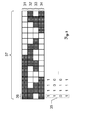
- FIG. 2 shows an illustration for explaining the inventive rotation angle range-dependent digital multi-track absolute coding.
- the plurality of tracks are formed and imaged by a series of plural rotation passes 31-34, thereby generating, in the respective rotation passage, the angular pattern corresponding to the corresponding track by modification of the laser beam (such as turn on and off).
- the respective rotation angle ranges 36 are each uniquely assigned a digital code 35 from a four-state state value sequence (which corresponds to four code tracks), which is based on a defined sequence of states with respect to the laser beam, wherein the states comprise a set of two different discrete states originate from the laser beam (eg a switched-on laser beam [white in the sample or shown unfilled] and a switched-off laser beam [shown in dark hatching]).
- the rotation angle ranges 36 are defined here via the figurative rolled-out or plane-shaped circumferential region 38 with respect to a rotation of the deflection means.
- 16 unique codes can be generated (two up 4). Each of the 16 defined angle ranges is uniquely assigned to one of the 16 codes.
- the codes are defined such that neighbor pairs of state value sequences of the codes respectively associated with directly adjacent rotation angle ranges differ in only one member (i.e., one state value at a time).
- the rotation angle ranges are each equidistant and equally distributed and defined directly adjacent to each other over the peripheral region 38.
- a signal can now be generated and sent to the evaluation unit for each incidence of the laser beam (ie per "strike").
- the corresponding rotation angle range in which the receiver must be well derived the desired laser receiver direction can be determined.
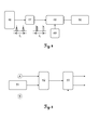
- FIG. 3 Fig. 11 is an illustration for explaining an example of the structure of the control for the laser unit (ie, an illustration for exemplifying the laser pattern encoder principle).
- the laser beam 14 emitted by the laser unit and exiting through the pentaprism may be controlled by a laser driver 43 (which is part of the control unit).
- the rotary encoder 42 provides information about the current angular position of the pentaprism.
- the codes are stored in the look-up table 45.
- This look-up table 45 now generates an ON / OFF signal for the laser driver 43 depending on the aforementioned signals from the state machine 44.
- the ON / OFF state with respect to the laser beam can be defined individually for the respective angular ranges and respective turning passes after application of the trigger signal B.
- FIG. 4 shows an illustration of which function the laser receiver can take purely by way of example in the context of the design laser system.
- the laser receiver is designed to measure the time t0 between two consecutive "strikes" by the laser beam on the laser beam detector 46, for which purpose the raw output signal of the laser beam detector 46 is passed through a trigger 47 and a counting circuit 48.
- the time t0 is communicated to the rotating laser via the in-vehicle radio module 50, as a multiple of a basic time unit (e.g., 1 ms).
- FIG. 5 shows an illustration for explaining an example of the structure of the evaluation unit (ie, an illustration for exemplifying the laser pattern decoder principle).
- the sequence of symbols thus created for a rotation angle range is independent of the rotation time of the deflection means.
- the decoder 53 converts the sequence of symbols into a valid, corresponding code number (which is assigned to the angular range in which the laser receiver is therefore located).
- the transmission time for the radio communication may be unknown, since the laser pattern encoding can be done independently and if necessary asynchronously from the decoding of the searched direction.
- the laser receiver does not require any prior knowledge of the codes used.
Abstract
Description
Die Erfindung betrifft ein Konstruktionslasersystem für Arbeiten im Bau- und/oder Innenausbau, aus Rotationslaser und Laserreceiver, mit hinsichtlich Bereitstellungsaufwand und Ausführungsgeschwindigkeit verbesserter Funktionalität zur Bestimmung einer Richtung in der sich der Laserreceiver aus Sicht des Rotationslasers befindet. Ferner betrifft die Erfindung ein entsprechendes Verfahren mit Rotationslaser und Laserreceiver, wobei in verbesserter Weise ein Bestimmen der Richtung, in der sich der Laserreceiver aus Sicht des Rotationslasers befindet, erfolgt, sowie ein Computerprogrammprodukt zur Ausführung dieses Verfahrens.The invention relates to a construction laser system for works in construction and / or interior design, of rotary laser and laser receiver, with respect to deployment effort and execution speed improved functionality for determining a direction in which the laser receiver from the viewpoint of the rotary laser is. Furthermore, the invention relates to a corresponding method with rotary laser and laser receiver, wherein in an improved manner, a determination of the direction in which the laser receiver is from the viewpoint of the rotary laser, takes place, and a computer program product for carrying out this method.
Es ist bekannt, auf Baustellen z.B. von Gebäuden oder bei Strassenbau- und/oder Erdbauarbeiten Rotationslaser einzusetzen. Insbesondere werden Rotationslaser eingesetzt, in denen ein durch eine Lasereinheit emittierter Laserstrahl (im sichtbaren oder infraroten Wellenlängenbereich) durch Ablenkung über ein rotierendes Umlenkprisma eine Bezugsfläche erzeugt, durch die dann eine präzise Ebenenreferenz (insbesondere eine Höhenreferenz im Fall einer horizontalen Ebene) bereitgestellt wird.It is known on construction sites e.g. use of buildings or in road construction and / or earthworks rotary laser. In particular, rotary lasers are used in which a laser beam emitted by a laser unit (in the visible or infrared wavelength range) generates a reference surface by deflection via a rotating deflection prism, which then provides a precise plane reference (in particular a height reference in the case of a horizontal plane).
Viele der heute existierenden Rotationslaser weisen dabei eine Strahl-Selbsthorizontierfunktionalität (auch bekannt als Self-Levelling) auf. Zur Erfüllung einer solchen Strahl-Selbsthorizontierfunktionalität sind verschiedene technische Lösungen bekannt, die zwar sowohl rein mechanischer Art sein können, sich heute jedoch meist auf Sensorik optischer Art stützen. Beispielsweise kann das insbesondere die Lasereinheit und das drehbare Umlenkprisma umfassende Herzstück des Rotationslasers (d.h. das Laser-Core-Modul) pendelnd aufgehängt sein, sodass eine Horizontalitätstreue unter Ausnutzung der Gravitation erzeugt werden kann. Das Laser-Core-Modul kann vorteilhaft dabei jedoch um zwei Achsen (zumindest geringfügig in einem Bereich von z.B. +5°) motorisiert präzise neigbar an einem äusseren Gehäuse des Geräts aufgehängt sein und mit einem Neigungssensor bzw. Horizintierungssensor ausgestattet sein, dessen Anzeige bzw. Signal ausgelesen und als Ausgangsgrösse für eine aktive Änderung der Neigungsstellung des Laser-Core-Moduls benutzt werden kann.Many of today's rotating lasers have a beam self-leveling functionality (also known as self-leveling). Various technical solutions are known for the fulfillment of such a beam self-horizontalization functionality, which may be both of a purely mechanical nature but today are mostly based on sensors of an optical type. For example, this may in particular be the laser unit and the rotatable deflection prism comprehensive core of the rotary laser (ie, the laser core module) be suspended pendulum, so that a Horizontalitätstreue can be generated by utilizing gravity. However, the laser core module can advantageously be suspended about two axes (at least slightly in a range of, for example, + 5 °) precisely tiltable on an outer housing of the device and be equipped with a tilt sensor or horizontal sensor whose display or Signal can be read and used as an output variable for an active change of the inclination position of the laser core module.
Je nach Ausbaustufe weisen bekannte Rotationslaser heute dabei auch eine Funktion (mit entsprechender Mechanik, Sensorik und Steuerung) zur gezielten, gewünschten Neigung der Laserebene relativ zur Horizontalen in einer oder zwei Richtungen auf. Dafür kann das insbesondere die Lasereinheit und das drehbare Umlenkprisma umfassende Herzstück des Rotationslasers gezielt motorisiert um eine Achse oder um zwei Achsen geneigt und in gewünschte Neigungsstellungen gebracht werden, sodass damit auch die Rotationsachse und folglich auch die aufgespannte Ebene gewünscht geneigt wird. Entsprechende Mechanismen, Sensoriken und Steuerungen dafür sind im Stand der Technik hinlänglich bekannt und z.B. in den Patentliteratur-Publikationen
Wird dabei der durch den Rotationslaser emittierte rotierende Laserstrahl im sichtbaren Spektrum ausgesendet und trifft dieser auf eine Fläche wie z.B. eine Wand, einen Boden oder eine Decke des Gebäudes, ist dort eine Bezugslinie als Basis für weitere Maßnahmen sichtbar.If the rotating laser beam emitted by the rotating laser is emitted in the visible spectrum and strikes a surface such as a wall, a floor or a ceiling of the building, a reference line is visible there as the basis for further measures.
Zum präzisen Übertragen der durch den rotierenden Laserstrahl angegebenen Bezugsebene bzw. Bezugshöhe z.B. auf eine Wand oder ins Gelände sind handhaltbare Laserempfänger (auch Laserreceiver genannt) bekannt, die eine Position relativ zu einer durch den Rotationslaser aufgespannten Referenzfläche hochgenau bestimmen und indizieren können.For precisely transmitting the reference plane or reference height indicated by the rotating laser beam, e.g. Hand-held laser receivers (also called laser receivers) are known on a wall or in the terrain, which can determine and index a position with high precision relative to a reference surface spanned by the rotary laser.
Aus dem Stand der Technik bekannte handhaltbare Laserempfänger zur Bestimmung einer Position relativ zur Referenzfläche können dabei einen eine Vielzahl von photosensitiven Elementen umfassenden Laserstrahl-Detektor aufweisen, der zur Erzeugung eines Ausgangssignals bei Auftreffen des Laserstrahls auf dem Laserstrahl-Detektor ausgebildet ist. Im Detail ist dabei der Laserstrahl-Detektor meist so ausgebildet, dass zudem eine Auftreffposition des Laserstrahls auf der Laserstrahl-Detektor-Fläche abgeleitet werden kann, wofür die photosensitiven Elemente - betrachtet in aufrechter Betriebsstellung des Geräts - in einer vertikal ausgerichteten Sensorzeile aneinander gereiht sein können, sodass sich also der Laserstrahl-Detektor zumindest über einen eindimensionalen Bereich auf dem Laserreceiver erstreckt. Zudem sind meistens eine Auswerteeinheit zur Ermittlung der Position des Laserempfängers relativ zur durch den rotierenden Laserstrahl definierten Referenzhöhe anhand des Outputs des Laserstrahl-Detektors sowie ein Indikator für die ermittelte Position (etwa eine visuelle Anzeige), insbesondere ausgebildet zur Indikation, ob der Laserempfänger mit der Referenzfläche exakt koinzidiert, in das Laserempfängergerät integriert. Die Position kann dabei beispielsweise anhand eines Verhältnisses von mehreren Ausgangssignalen bestimmt werden (z.B. als Mittelpunkt jenes Teil-Bereichs auf der Laserstrahl-Detektor-Zeile, der durch den Laserstrahl beleuchtet wird).Hand-held laser receivers known from the prior art for determining a position relative to the reference surface may comprise a laser beam detector comprising a plurality of photosensitive elements, which is designed to generate an output signal upon impact of the laser beam on the laser beam detector. In detail, the laser beam detector is usually designed so that in addition an impact position of the laser beam on the laser beam detector surface can be derived, for which the photosensitive elements - viewed in upright operating position of the device - in a vertically aligned sensor line can be strung together such that the laser beam detector thus extends over at least a one-dimensional area on the laser receiver. In addition, most often an evaluation unit for determining the position of the laser receiver relative to the reference height defined by the rotating laser beam based on the output of the laser beam detector and an indicator for the determined position (such as a visual display), in particular designed for indicating whether the laser receiver with the Reference surface exactly coincident, integrated into the laser receiver device. The position can be determined, for example, on the basis of a ratio of a plurality of output signals (eg as a midpoint that part area on the laser beam detector line illuminated by the laser beam).
Derartige handhaltbare Laserempfänger können insbesondere dann zum Einsatz kommen, wenn die durch den rotierenden Laserstrahl abgebildete Linie mit dem Auge nur schwer oder nicht präzise genug erkennbar ist. Dies ist z.B. der Fall etwa bei grösseren Entfernungen von Rotationslaser (z.B. begründet auf eine Divergenz des Laserstrahls [-> abgebildete Linie wird zu breit] oder eine geringe Lichtleistung [-> abgebildete Linie wird zu schwach sichtbar] (die aus Augensicherheitsgründen gewissen Begrenzungen unterliegt) und/oder eine hohe Umgebungshelligkeit) oder auch bei Verwendung von Laserlicht im nicht sichtbaren Wellenlängenbereich.Such hand-held laser receiver can be used in particular when the line imaged by the rotating laser beam with the eye is difficult or not precise enough recognizable. This is e.g. the case for example at longer distances from rotating laser (eg due to a divergence of the laser beam [-> imaged line becomes too wide] or a low light output [-> imaged line becomes too weak] (which is subject to certain limitations for eye safety reasons) and / or a high ambient brightness) or even when using laser light in the non-visible wavelength range.
In solchen Fällen ist es anhand derartiger Laserempfänger nun ermöglicht, den Laserstrahl zu finden und die durch einen rotierenden Laserstrahl definierte Laserebene (bzw. Referenzhöhe) zu indizieren, abzulesen und die Höheninformation ins Gelände bzw. auf eine Wand (etc.) zu übertragen. Beispielsweise kann - indiziert durch den Laserempfänger - eine entsprechende Markierung in der Referenzhöhe angebracht werden.In such cases, it is now possible on the basis of such laser receiver to find the laser beam and to index the defined by a rotating laser beam laser plane (or reference height), read and transfer the altitude information to the ground or on a wall (etc.). For example, - indicated by the laser receiver - a corresponding mark in the reference height can be attached.
Dafür wird benutzerseitig der Laserempfänger beispielsweise in vertikaler Richtung suchend auf und ab bewegt und schliesslich in jene Position gebracht, in welcher der Indikator eine Koinzidenz mit der Referenzfläche anzeigt. Beispielsweise kann als Indikator eine visuelle Anzeige vorgesehen sein, die (etwa durch Leuchtpfeile oder unterschiedlichfarbene LEDs) darüber informiert, ob sich ein definierter Nullpunkt des Laserempfängers (z.B. ein Flächenmittelpunkt der Detektorfläche)
- □ exakt auf Höhe der Referenzfläche,
- □ oberhalb der Referenzfläche oder
- □ unterhalb der Referenzfläche
- □ exactly at the height of the reference surface,
- □ above the reference surface or
- □ below the reference surface
Beispiele für solche Laserempfänger sind in den Druckschriften
Um dem Benutzer ein einfaches Übertragen der durch den Laserempfänger ermittelten und indizierten Referenzhöhe bereitzustellen, kann am Gehäuse des Laserempfängers in Höhe des definierten Nullpunkts eine Höhenmarke vorgesehen sein (z.B. eine Kerbe oder eine aufgedruckte Linie seitlich am Gehäuse).To provide the user with easy transfer of the reference height determined and indexed by the laser receiver, a height mark may be provided on the housing of the laser receiver at the level of the defined zero point (e.g., a notch or a printed line on the side of the housing).
In der
In der
Für eine Reihe von bekannten Funktionen und Anwendungen eines Systems aus Rotationslaser (insbesondere Dual-Grade-Rotationslaser) und Laserreceiver kann zudem (z.T. zumindest grobe) Kenntnis über eine Laserreceiver-Richtung erforderlich oder zumindest hilfreich sein, d.h. Kenntnis über eine Richtung, in welcher sich der Laserreceiver aus Sicht des Rotationslasers befindet (z.B. bzgl. eines Rotationslaser-internen Koordinatensystems).Moreover, for a number of known functions and applications of a system of rotary laser (in particular dual-grade rotary laser) and laser receiver, knowledge of a laser receiver direction may be necessary or at least helpful (at least rough). Knowledge of a direction in which the laser receiver is from the viewpoint of the rotating laser (e.g., a rotating laser-internal coordinate system).
Beispiele für derartige Funktionen und Anwendungen können dabei sein:
- a) Grade-Catch (auch Plane-Catch oder Slope-Catch genannt), z.B. bei Verlust des Receivers aus dem eingelockten Zustand (siehe b)):
- Es erfolgen ein Aufsuchen des Receivers durch variierendes Neigen der durch den rotierenden Laserstrahl aufgespannten Referenzebene und ein Auffinden in Abhängigkeit von einem vom Receiver an den Rotator gesendeten Treffer-Signal.
- Ist (z.B. aus einem vorherigen eingelockten Zustand) eine azimutale Richtung zum Receiver bekannt, so kann unter Zuhilfenahme dieser Laserreceiver-Richtung der Aufsuchvorgang beschleunigt werden (weniger Unsicherheiten vorhanden für das Durchführen des Aufsuchvorgangs). Ist zudem bekannt, ob der Laserreceiver die Ebene aus dem eingelockten Zustand nach oben oder unten verlassen hat, kann - wiederum unter Zuhilfenahme der Laserreceiver-Richtung - der Aufsuchvorgang nochmals zielgerichteter ausgeführt werden.
- b) Grade-Lock (auch Plane-Lock bzw. Slope-Lock genannt, ggf. mit Tracking), was nur dann erfolgen kann, wenn die Referenzebene bereits (zumindest irgendwo) auf den Detektorbereich des Receivers trifft, also insbesondere direkt anschliessend an ein Grade-Catch (d.h. nach "Auffinden" des Receivers):
- Es erfolgen ein Einlocken der Referenzebene im Nullpunkt des Receivers (also gezieltes Neigen der Referenzebene, sodass diese den Nullpunkt des Receivers schneidet) und ein ggf. fortlaufendes Halten dieses Zustands (z.B. auch bei Bewegen des Receivers, was dann Tracking genannt wird), wobei durch gezieltes Nachstellen der Referenzebenenneigung fortlaufend dafür gesorgt wird, dass der Nullpunkt des Receivers mit der Referenzebene getroffen wird bzw. die Referenzebene schneidet).
- Das Tracking (d.h. die Nachführung der Referenzebene durch gezieltes Neigen derselben) kann bei dynamischer Bewegung des Receivers nur dann hinreichend schnell und erfolgen, wenn direkt bekannt ist, auf welche receiverseitig gemessene Abweichung zwischen aktuellem Referenzebenenauftreffpunkt und Nullpunkt des Laserreceivers mit welcher Neigungsverstellung reagiert werden muss. Hierfür kann Kenntnis über die Laserreceiver-Richtung sehr hilfreich sein, um diesen Trackingprozess zu stabilisieren, direkter zu machen und somit eine schnellere und dynamischere Nachführung zu ermöglichen.
- c) Axis-Alignment/Axis-Finding:
- Es kann ein benutzerseitiges Definieren von fiktiven x'-und y'-Achsen erfolgen (d.h. fiktive Achsen, die nicht mit der aufstellungs- und konstruktionsbedingten Ausrichtung der tatsächlichen x-Neigungs- und Y-Neigungsachsen des Core-Moduls übereinstimmen), um welche die Laserebene wie vom Benutzer eingegeben geneigt werden soll. Diese benutzerseitige Eingabe der gewünschten Ausrichtung der fiktiven x'- und y'-Achsen kann erfolgen anhand von einer aktuellen Richtung zum Receiver, die es zu bestimmen gilt (sodass z.B. die fiktive x'-Achse in diese azimutale Richtung zum Receiver gelegt werden kann).
- a) Grade-Catch (also called tarp-catch or slope-catch), eg if the receiver is lost from the locked state (see b)):
- The receiver is located by varying the inclination of the reference plane defined by the rotating laser beam and finding it as a function of a hit signal sent by the receiver to the rotator.
- If an azimuthal direction to the receiver is known (for example, from a previous locked state), the search process can be accelerated with the aid of this laser receiver direction (fewer uncertainties exist for carrying out the search operation). It is also known if the laser receiver is out of the plane Locked state has left up or down, can - again with the aid of the laser receiver direction - the search process again targeted to be executed.
- b) Grade-Lock (also called Plane-Lock or Slope-Lock, possibly with tracking), which can only be done if the reference plane already (at least somewhere) on the detector area of the receiver meets, so in particular directly afterwards to a Grade-Catch (ie after "finding" the receiver):
- There is an entrapment of the reference plane in the zero point of the receiver (ie targeted tilting of the reference plane, so that this cuts the zero point of the receiver) and a possibly continuous holding this state (eg even when moving the receiver, which is called tracking), where by specific adjustment of the reference plane inclination is continuously ensured that the zero point of the receiver is hit with the reference plane or intersects the reference plane).
- The tracking (ie the tracking of the reference plane by deliberately tilting the same) can only be sufficiently fast and dynamic when the receiver is moving, if it is known directly to which receiver-side measured deviation between the current reference plane impact point and zero point of the laser receiver must be reacted with which tilt adjustment. For this, knowledge about the laser receiver direction can be very helpful to this tracking process stabilize, direct and thus enable a faster and more dynamic tracking.
- c) Axis Alignment / Axis Finding:
- User-defined definition of fictitious x 'and y' axes (ie fictitious axes that do not match the placement and design orientation of the actual x-pitch and y-pitch axes of the core module) may be used Laser plane as intended to be tilted by the user. This user-input of the desired alignment of the fictitious x'- and y'-axes can be made on the basis of a current direction to the receiver, which has to be determined (so that eg the fictitious x'-axis can be placed in this azimuthal direction to the receiver) ,
Des Weiteren kann zum Zwecke des Axis-Alignment auch eine unterstützende Funktionalität dergestalt verwirklicht sein, dass eine Signalisierung bezüglich der Qualität der Ausrichtung der Neigungsachse erfolgt, etwa durch eine Anzeige, welche die benutzerseitig bewirkte Ausrichtung des Laser-Core-Moduls unterstützt (beispielsweise eine Wertangabe oder eine Links-/Rechts-/Mitte-Information). Dies ist insbesondere dann vorteilhaft, wenn das Neigungssystem konstruktionsbedingt keine Bereitstellung fiktiver x'- und y'-Achsen ermöglicht, wie es etwa bei Rotationslasersystemen in geringeren Ausbaustufen mit ausschliesslicher Horizontierfunktion (Self-Levelling), welche über keine Mittel der mechanischen Rotation der Neigungsachse(n) verfügen.Furthermore, for the purpose of axis alignment, a supporting functionality can also be realized in such a way that a signal regarding the quality of the orientation of the tilt axis is made, for example by a display which supports the user-directed alignment of the laser core module (for example an indication of value) or left / right / center information). This is particularly advantageous if the inclination system by design does not allow the provision of fictitious x'- and y'-axes, as in rotary laser systems in smaller stages with exclusive leveling function (self-leveling), which no means of mechanical rotation of the tilt axis ( n).
Berührungspunkt dieser Funktion mit Laserreceiver-Richtung: Für diese Funktion (zumindest bei Definition der fiktiven x'- und y'-Achsen über eine aktuelle Richtung zum Receiver) ist Kenntnis über die Laserreceiver-Richtung erforderlich.Touch point of this function with laser receiver direction: Knowledge of the laser receiver direction is required for this function (at least when defining the fictitious x 'and y' axes via a current direction to the receiver).
Spezielle Aspekte und Ausführungsformen bzgl. dieser Funktionen sind z.B. in den Patentliteratur-Publikationen
Folgende Methoden sind dabei (unter anderem auch aus den im direkt vorherigen Abschnitt genannten Publikationen) für die Bestimmung einer Laserreceiver-Richtung in einem System aus Rotationslaser und Laserreceiver im Stand der Technik unter anderem bekannt:
- 1) Auswertung eines direkt (in Echtzeit) nach receiverseitiger Detektion eines Strahls erzeugten Signals, das vom Receiver an den Rotator (z.B. per Funk) übertragen wird und Ableiten eines Emissionswinkels, in welchem der rotierende Laserstrahl wohl gerade zum Zeitpunkt des Auftreffens stand
- 2) Definiertes Neigen der Referenzebene um einen bekannten Neigungswert und laserreceiverseitiges Ablesen eines dadurch bewirkten Höhenversatzes des Beam-Strikes auf dem Detektor des Laserreceivers (mit Durchführung dieser Schritte für beide Neigungsachsen) und Ableiten einer Richtung zum Receiver anhand von der gegebenen Relation des jeweiligen Neigungswinkelunterschieds zum jeweiligen Höhenversatz auf dem Receiver.
- 3) Behaftung eines Strahlparameters der Laserstrahlung mit einer kontinuierlich winkelabhängig variierenden Information, die seitens des Receivers anhand des auftreffenden Strahls auslesbar ist und darüber die Richtung zum Receiver ableitbar macht.
- 4) Iterativ halbierendes Windowing anhängig von einem Treffen bzw. Nichttreffen des Laserreceivers im jeweils aktuellen Winkelbereichs-Fenster (z.B. Aussenden des Strahls nur im Winkelbereich von 0 - 180°, falls Receiver einen Treffer angezeigt hat: Aussenden des Strahls nur im Winkelbereich von 0 - 90°, falls Receiver bei 0 - 180° keinen Treffen angezeigt hat: Aussenden des Strahls nur im Winkelbereich von 180° - 270°, etc.).
- 1) Evaluation of a signal generated directly (in real time) according to the receiver side of a beam, which is transmitted from the receiver to the rotator (eg by radio) and deriving an emission angle in which the rotating laser beam was just at the time of impact
- 2) Defined tilting of the reference plane by a known slope value and reading of a resulting beam offset on the detector of the laser receiver (performing these steps for both tilt axes) and deriving a direction to the receiver based on the given relation of the respective tilt angle difference respective height offset on the receiver.
- 3) Adherence of a beam parameter of the laser radiation with a continuously angle-varying information, the side of the receiver on the basis of incident beam is readable and about the direction makes it derivable to the receiver.
- 4) Iteratively halved windowing depending on a meeting or non-arrival of the laser receiver in the current angle range window (eg emitting the beam only in the angle range of 0 - 180 °, if Receiver has indicated a hit: emitting the beam only in the angle range of 0 - 90 °, if receiver has not indicated a meeting at 0 - 180 °: emission of the beam only in the angular range of 180 ° - 270 °, etc.).
Das Thema bzgl. einer Bestimmung der Laserreceiver-Richtung wird dabei unter anderem auch in der Patentliteratur-Publikation
In der Praxis haben sich die bekannten Methoden zur Bestimmung der Richtung jedoch als langsam, wenig stabil, wenig verlässlich und/oder aufwändig bzw. schwierig in der praktischen Umsetzung herausgestellt.In practice, however, the known methods for determining the direction have proven to be slow, less stable, less reliable and / or expensive or difficult to implement in practice.
Methoden wie unter Punkt 1) oben beschrieben, die auf der Übertragung eines Signals vom Laserreceiver zum Rotationslaser, welches vom Zeitpunkt des Strikes auf dem Laserreceiver abhängt, und einer daraus direkt erfolgenden Ableitung der Richtungsinformation (also auf eine Echtzeitbetrachtung) gründen, sind wenig genau (da die Signal-Übertragungszeit von der jeweiligen Entfernung zwischen Receiver und Rotator abhängt) und nicht verlässlich.Methods as described in point 1) above, which are based on the transmission of a signal from the laser receiver to the rotating laser, which depends on the time of the strikes on the laser receiver, and a direct derivation of the direction information (ie on a real-time view) are not very accurate ( because the signal transmission time depends on the distance between receiver and rotator) and not reliable.
Die Methoden wie unter Punkte 2) und 4) oben beschrieben sind bei Ihrer Ausführung vergleichsweise langwierig und erfordern diverse verschiedene Schritte und/oder Entscheidungsfindungen, sodass sich dadurch auch eine vergleichsweise hohe Fehleranfälligkeit ergibt. Ferner funktioniert die Methode wie unter Punkt 2) beschrieben nur bei einem aufrecht gehaltenen Receiver (bzw. führt ein schräges Halten des Receivers zu einem verfälschten Ergebnis).The methods described in points 2) and 4) above are comparatively lengthy in their execution and require various different steps and / or decision making, so that thereby also a comparatively high susceptibility to errors. Furthermore, the method as described in point 2) only works with a receiver held upright (or a slanted holding of the receiver leads to a falsified result).
Die Methode wie unter Punkt 3) beschrieben ist dabei sehr aufwändig zu realisieren, da eine Behaftung der Laserstrahlung mit kontinuierlich variierender Information erforderlich ist und zudem auch receiverseitig eine spezielle Erfassung des auftreffenden Laserstrahls (d.h. so, dass die anhaftende Information nicht verloren geht) und Auswertung hinsichtlich der Information zu erfolgen hat. Ein kontinuierlich winkelabhängig variierter Strahlparameter der Laserstrahlung kann dabei zudem bei der Auswertung eines bei Detektion der Laserstrahlung erzeugten Signals zu Ungenauigkeiten in der letztendlichen Winkelbestimmung führen (z.B. wenn sich eine globale Verschiebung des Parameters in seinem Wert, welcher winkelabhängig variiert wird, einschleicht (etwa aufgrund von Schock oder Veralterung des Geräts)).The method as described under point 3) is very complex to implement, since an adhesion of the laser radiation with continuously varying information is required and also on the receiver side a specific detection of the incident laser beam (ie so that the adhering information is not lost) and evaluation for information purposes. In addition, a beam parameter of the laser radiation which is continuously varied as a function of the angle can lead to inaccuracies in the final angle determination during evaluation of a signal generated upon detection of the laser radiation (eg if a global shift of the parameter in its value, which is varied as a function of angle (for example due to Shock or obsolescence of the device)).
Aufgabe der Erfindung ist somit das Bereitstellen eines hinsichtlich einer Funktionalität zur Bestimmung einer Laserreceiver-Richtung verbesserten Konstruktionslasersystems aus Rotationslaser und Laserreceiver.The object of the invention is therefore to provide a design laser system of rotary laser and laser receiver which is improved in terms of functionality for determining a laser receiver direction.
Insbesondere soll dabei die Funktionalität zur Bestimmung einer Laserreceiver-Richtung robuster, schneller, zuverlässiger und/oder weniger aufwändig für die Umsetzung in der Praxis sein.In particular, the functionality for determining a laser receiver direction should be more robust, faster, more reliable and / or less expensive for implementation in practice.
Diese Aufgaben werden durch die Verwirklichung der kennzeichnenden Merkmale der unabhängigen Ansprüche gelöst. Merkmale, die die Erfindung in alternativer oder vorteilhafter Weise weiterbilden, sind den abhängigen Patentansprüchen zu entnehmen.These objects are achieved by the realization of the characterizing features of the independent claims. Features which further develop the invention in an alternative or advantageous manner can be found in the dependent claims.
Das erfindungsgemässe Konstruktionslasersystem umfasst mindestens einen eine Lasereinheit und ein drehbares Umlenkmittel aufweisenden Rotationslaser zur Emission eines rotierenden Laserstrahls, wobei der rotierende Laserstrahl eine Referenzfläche definiert, und einen Laserempfänger mit einem zumindest sich über einen eindimensionalen Bereich auf dem Laserreceiver erstreckenden Laserstrahl-Detektor, der ausgebildet ist zur Erzeugung eines Ausgangssignals abhängig von einem Auftreffen des Laserstrahls auf dem Laserstrahl-Detektor. Zudem ist eine Auswerteeinheit vorgesehen zur Bestimmung von einer Laserreceiver-Richtung, in welcher sich der Laserreceiver aus Sicht des Rotationslasers befindet.The inventive design laser system comprises at least one rotating laser comprising a laser unit and a rotatable deflection means for emitting a rotating laser beam, the rotating laser beam defining a reference surface, and a laser receiver having a laser beam detector extending at least over a one-dimensional area on the laser receiver for generating an output signal depending on an impact of the laser beam on the laser beam detector. In addition, an evaluation unit is provided for determining a laser receiver direction in which the laser receiver is located from the perspective of the rotary laser.
Die Erfindung löst sich dabei vom Stand der Technik, indem zur Bestimmung der Laserreceiver-Richtung nun ein drehwinkelbereichsabhängiges digitales mehrspuriges Codemuster verwendet wird, wobei die mehreren Spuren hier durch eine Reihe von mehreren Drehdurchgängen erzeugt und abgebildet werden, und im jeweiligen Drehdurchgang das der zugehörigen Spur entsprechende Winkelbereichsmuster über Modifikation des Laserstrahls (wie z.B. An- und Ausschaltung) erzeugt wird.The invention solves this from the prior art by now to the determination of the laser receiver direction a rotation angle range-dependent digital multi-track code pattern is used, wherein the plurality of tracks are generated and imaged here by a series of multiple rotation passes, and in the respective rotation passage that of the associated track corresponding angle range pattern is generated by modification of the laser beam (such as switching on and off).
Receiverseitig kann nun pro Auftreffen des Laserstrahls (also pro "Strike") ein Signal erzeugt und an die Auswerteeinheit gesendet werden. Dort kann anhand einer Verarbeitung der Folge von eingegangenen Signalen - in Kenntnis des mehrspurigen Codemuster - der entsprechende Drehwinkelbereich, in welchem sich der Receiver wohl befinden muss, abgeleitet und somit die gesuchte Laserreceiver-Richtung bestimmt werden.On the receiver side, a signal can now be generated and sent to the evaluation unit for each incidence of the laser beam (ie per "strike"). There, based on a processing of the sequence of received signals - in Knowledge of the multi-track code pattern - the corresponding rotation angle range in which the receiver must be well located, derived and thus the sought Laserreceiver direction can be determined.
Mit anderen Worten sind dafür erfindungsgemäss in einem Speicher Information gespeichert über
- eine Vielzahl von definierten Drehwinkelbereichen bezüglich einer Drehung des Umlenkmittels und
- einen den jeweiligen Drehwinkelbereichen jeweils eindeutig zugeordneter digitaler Code aus einer Zustandswertefolge, die auf eine definierte Abfolge von Zuständen bezüglich des Laserstrahls gründet, wobei die Zustände aus einer Menge von zumindest zwei definierten unterschiedlichen diskreten Zuständen bezüglich des Laserstrahls stammen.
- a plurality of defined rotation angle ranges with respect to a rotation of the deflection means and
- a digital code uniquely assigned to the respective rotation angle ranges from a state value sequence based on a defined sequence of states with respect to the laser beam, the states being from a set of at least two defined different discrete states with respect to the laser beam.
Ferner ist nun eine Steuereinheit vorhanden zur derartigen umlenkmitteldrehungssynchronisierten Steuerung der Lasereinheit hinsichtlich Erzeugung von den zumindest zwei unterschiedlichen diskreten Zuständen, dass in den jeweiligen Drehwinkelbereichen jeweils die dem jeweiligen Drehwinkelbereich entsprechende Abfolge von Zuständen bezüglich des Laserstrahls über - bei Ablauf von einer Reihe von Drehdurchgängen des Umlenkmittels - nacheinander erfolgende Durchquerungen des jeweiligen Drehwinkelbereichs erzeugt wird.Furthermore, a control unit is now provided for such deflection-synchronized control of the laser unit with respect to generation of the at least two different discrete states that in the respective rotation angle ranges corresponding to the respective rotation angle range sequence of states with respect to the laser beam - at the end of a series of rotational passages of the deflection - Successive traversals of the respective rotation angle range is generated.
Auswerteeinheitsseitig kann schliesslich eine Ausgangssignal-Folge von nacheinander eintreffenden Ausgangssignalen erfasst werden, eine zu der Ausgangssignal-Folge korrespondierende Zustandswertefolge aus den gespeicherten Zustandswertefolgen identifiziert werden und die Laserreceiver-Richtung bestimmt werden abhängig von jenem Drehwinkelbereich, welcher dem der identifizierten Zustandswertefolge entsprechenden Code zugeordnet ist.Evaluation unit side, finally, an output signal sequence of successive incoming output signals are detected, a corresponding to the output signal sequence state value sequence identified from the stored state value sequences and the laser receiver direction are determined depending on the rotation angle range associated with the code corresponding to the identified state value sequence.
Erfindungsgemäss kann somit bei der Richtungsbestimmung sowohl auf eine ansonsten fehleranfällige Live-Adaption mit verschiedenen Entscheidungsfindungen beim Vorgang (siehe z.B. die Methoden wie eingangs unter den Punkten 2) und 4) beschrieben) als auch auf eine spezielle geräteseitige Ausbildung des Laserreceivers (siehe z.B. die Methode wie eingangs unter Punkt 3) beschrieben) verzichtet werden.According to the invention can thus in the direction determination both on an otherwise error-prone live adaptation with different decision making during the process (see, for example, the methods described at the beginning under the points 2) and 4) described) as well as on a specific device-side training of the laser receiver (see eg the method as described at the beginning of item 3)).
Ferner ist der erfindungsgemässe Vorgang für die Richtungsbestimmung vollautomatisch ablaufbar, wobei dieser vollumfänglich stets strikt nach vorgegebenem Schema erfolgen kann und somit hinsichtlich benötigter Zeitdauer als auch hinsichtlich des zu erwartenden Ergebnisses (z.B. was die Genauigkeit der Richtungsbestimmung betrifft) konstant und verlässlich ist.Furthermore, the process according to the invention for determining the direction can be executed fully automatically, whereby this process can always be carried out strictly in accordance with a predefined scheme and thus constant and reliable with respect to the required time duration as well as with regard to the expected result (for example as regards the accuracy of the direction determination).
So ist beim erfindungsgemässen Vorgehen keine Interaktion (lediglich eine Kommunikation) zwischen den Funktionseinheiten des Systems erforderlich, und jede der Funktionseinheiten des Systems kann nach einem genau vorgegebenen Schema seine Tätigkeit abspulen. Insbesondere dauert dann jede Richtungsbestimmung prinzipiell genau gleich lang und sie stellt verlässlich, robust und im Wesentlichen unabhängig von äusseren Einflüssen die bestimmte Richtung mit gleich bleibendem und genau systembedingt bekanntem Maximalabweichungsfehler (auch bei Alterung des Geräts, etc.) bereit.Thus, in the method according to the invention, no interaction (merely communication) between the functional units of the system is required, and each of the functional units of the system can perform its task according to a precisely predetermined scheme. In particular, then each direction determination takes in principle exactly the same length and it provides reliable, robust and essentially independent of external influences, the particular direction with a constant and exactly systemally known maximum deviation error (even with aging of the device, etc.) ready.
Des Weiteren kann erfindungsgemäss faktisch nun auf eine Echtzeitauswertung verzichtet werden, bei welcher das erzielbare Ergebnis davon abhängt, wie präzise einzelne Ereignissen in zeitliche Beziehung zueinander gebracht werden können (siehe z.B. die Methode wie eingangs unter Punkt 1) beschrieben). Eine zeitinformationshinterlegte Erfassung von jeweiligen "Strikes" auf dem Receiver ist - je nach Ausführungsform der Erfindung - allenfalls nur dann und höchstens jedoch nur mit solcher zeitlicher Genauigkeit/Korrelation erforderlich, soweit dies für das Zuordnen von den Ausgangssignalen der erfassten Ausgangssignal-Folge zu den entsprechenden Drehruchgängen der Reihe von vorgegebenen Drehdurchgängen vonnöten ist. Rein beispielhaft wäre also bei einer Umdrehungsgeschwindigkeit von 10 Umdrehungen pro Sekunde für solche Ausführungsformen der Erfindung, die überhaupt gewissermassen eine Zeitinformationshinterlegung erfordern, eine zeitliche Auflösung von einer Zehntelsekunde ausreichend.Furthermore, according to the invention, a real-time evaluation can actually be dispensed with in which the achievable result depends on how precise individual events can be brought into temporal relation to one another (see, for example, the method as described under point 1). Depending on the embodiment of the invention, a time-sensitive recording of respective "strikes" on the receiver is only required if at most and only with such temporal accuracy / correlation, as far as this is for the assignment of the output signals of the detected output signal sequence to the corresponding Rotation turns the series of predetermined rotation passes is needed. By way of example only, at a rotational speed of 10 revolutions per second, for such embodiments of the invention, which to some extent require time-information back-up, a temporal resolution of one-tenth of a second would be sufficient.
Somit wird erfindungsgemäss also ein hinsichtlich der Funktionalität zur Bestimmung einer Laserreceiver-Richtung verbessertes Konstruktionslasersystems aus Rotationslaser und Laserreceiver bereitgestellt. Ferner kann somit die Funktionalität zur Bestimmung einer Laserreceiver-Richtung auch verbessert in verrauschten/gestörten Umgebungen, robuster, schneller, zuverlässiger und/oder weniger aufwändig für die Umsetzung in der Praxis umgesetzt werden.Thus, according to the invention, a design laser system comprising a rotating laser and a laser receiver, which is improved in terms of functionality for determining a laser receiver direction, is thus provided. Furthermore, the functionality for determining a laser receiver direction can thus also be improved in noisy / disturbed environments, more robust, faster, more reliable and / or less complicated to implement in practice.
Durch die erfindungsgemässe Unabhängigkeit von einer Funkdatenübertragungs-Verzögerung kann die Bestimmung der Laserreceiver-Richtung nun zudem auch über grosse Distanzen zwischen Laserreceiver und Rotationslaser erfolgen.Due to the inventive independence of a radio data transmission delay, the determination of the laser receiver direction can now also be done over long distances between laser receiver and rotary laser.
Gemäss eines Aspekts der Erfindung können die im Speicher gespeicherten Drehwinkelbereiche über einen Umfangbereich von mindestens 180° bezüglich der Drehung des Umlenkmittels definiert sein. Insbesondere können diese jedoch über den vollen Umfang einer Drehung, d.h. über einen Umfangbereich von 360° bezüglich der Drehung des Umlenkmittels, definiert sein.According to one aspect of the invention, the rotational angle ranges stored in the memory can be defined over a circumferential range of at least 180 ° with respect to the rotation of the deflection means. In particular, however, they can be varied over the full extent of rotation, i. over a circumferential range of 360 ° with respect to the rotation of the deflection, to be defined.
Dabei können z.B. mindestens 30, insbesondere mindestens 100, im Speziellen mindestens 500, Drehwinkelbereiche über den Umfangbereich definiert sein. Je nach dem, wie viele Drehwinkelbereiche dabei vorgesehen sind, ist unter Berücksichtigung der vorgesehenen Anzahl von unterscheidbaren Zuständen bezüglich des Laserstrahls auch eine entsprechende Anzahl von Codespuren bzw. Länge der Zustandswertefolge (und somit auch eine entsprechende Anzahl von Drehdurchgängen und dabei erfolgenden Durchquerungen der jeweiligen Drehwinkelbereiche) erforderlich.Thereby, e.g. be defined at least 30, in particular at least 100, in particular at least 500, rotational angle ranges over the peripheral region. Depending on how many rotation angle ranges are provided, taking into account the intended number of distinguishable conditions with respect to the laser beam, a corresponding number of code tracks or length of the state value sequence (and thus also a corresponding number of rotation passes and thereby traversing the respective rotation angle ranges ) required.
Stammen die herstellbaren Zustände dabei z.B. aus einer Menge von genau zwei definierten unterschiedlichen diskreten Zuständen bezüglich des Laserstrahls, so sind für die Realisierung von 100 Drehwinkelbereichen mindestens sieben Codespuren (d.h. ein Code aus mindestens sieben Zustandswerten) vonnöten, da dies der kleinsten, die Zahl 100 abdeckenden Zweierpotenz (also Potenz zur Basis 2) entspricht.If the conditions that can be produced thereby include e.g. from a set of precisely two defined different discrete states with respect to the laser beam, at least seven code tracks (ie a code of at least seven state values) are required for the realization of 100 rotational angle ranges, since this is the smallest power of two covering the number 100 (ie power to Base 2) corresponds.
Insbesondere können die Drehwinkelbereiche dabei jeweils gleichweit und gleich verteilt und direkt aneinander angrenzend über den Umfangbereich definiert sein.In particular, the rotational angle ranges can each be equidistant and equally distributed and be defined directly adjacent to one another over the circumferential region.
Gemäss eines weiteren Aspekts der Erfindung können die im Speicher gespeicherten Codes derart definiert sind, dass sich Nachbar-Paare von Zustandswertefolgen von Codes, die jeweils direkt benachbarten Drehwinkelbereichen zugeordnet sind, um jeweils nur einen Wert unterscheiden.According to a further aspect of the invention, the codes stored in the memory can be defined in such a way that adjacent pairs of state value sequences of codes, which are respectively assigned to directly adjacent rotation angle ranges, differ by only one value at a time.
Dies entspricht dem Prinzip, das auch bei Drehschaltern zur Anwendung kommt und kann den Vorteil haben, dass bei fehlerhafter Detektion/Berücksichtigung von einem Zustand (also einer Spur) aus dem Code die Richtungsbestimmung nicht völlig falsch sondern möglicherweise nur um einen direkt benachbarten Drehwinkelbereich verfehlt erfolgt.This corresponds to the principle that is also used with rotary switches and can have the advantage that in case of erroneous detection / consideration of a state (ie a track) from the code, the direction determination is not completely wrong but possibly only missed by a directly adjacent rotation angle range ,
Alternativ kann jedoch die Definition bzw. Zuordnung der Codes zu den jeweiligen Drehwinkelbereichen auch zufällig oder nach einem anderen speziellen Zuordnungsmuster erfolgen, wobei wesentlich ist, dass eine eindeutige Zuordnung (und somit eine eindeutige Ableitbarkeit eines entsprechenden Drehwinkelbereichs anhand eines identifizierten Codes) gewährleistet ist (Absolutcodierung).Alternatively, however, the definition or assignment of the codes to the respective rotation angle ranges can also take place randomly or according to another special assignment pattern, wherein it is essential that an unambiguous assignment (and thus an unambiguous derivability of a corresponding rotation angle range from an identified code) is ensured (absolute coding ).
Wie zuvor erwähnt hängt die benötigte Codespurenanzahl - je nach vorgesehener Menge von unterscheidbaren Zuständen des Laserstrahls - von der gewünschten Winkelauflösung bzw. von der Anzahl von im Code abzudeckenden/bereitzustellenden Drehwinkelbereichen ab. Vorteilhaft sind die im Speicher gespeicherten Codes beispielsweise derart definiert, dass die Zustandswertefolgen jeweils eine Zustandswertefolgen-Gliederanzahl von mindestens fünf Zustandswerten umfassen (d.h. der Code mindestens fünf Spuren aufweist).As previously mentioned, the number of code tracks required depends on the desired angular resolution or number of rotational angle ranges to be covered / provided in the code, depending on the intended amount of distinguishable states of the laser beam. Advantageously, the codes stored in the memory are defined, for example, such that the state value sequences each comprise a state value sequence number of links of at least five state values (i.e., the code has at least five tracks).
Die Steuereinheit kann im einfachen Fall dabei dann in Abhängigkeit der vorgesehenen Anzahl von Codespuren zur derartigen Steuerung der Lasereinheit ausgebildet sein, dass die jeweiligen Abfolgen von Zuständen bei einer anzahlig mit der Zustandswertefolgen-Gliederanzahl (also Codespuren-Anzahl) korrespondierenden Reihe von Drehdurchgängen erzeugt werden.The control unit can then in the simple case then depending on the intended number of code tracks for Such control of the laser unit may be configured such that the respective sequences of states are generated at a number of rotational passes corresponding to the state value sequence number of links (ie code track number).
Im einfachsten Beispiel ist dabei die Codespuren-Anzahl gleich der Drehdurchgangsanzahl von der Reihe von Drehdurchgängen, über die der Code mit dem Laserstrahl abgebildet wird, sodass also - mit anderen Worten - in diesem Beispiel die jeweiligen Abfolgen von Zuständen bei einer Reihe von Drehdurchgängen erzeugt werden, die anzahlig gleich ist mit der Zustandswertefolgen-Gliederanzahl (also der Codespuren-Anzahl).In the simplest example, the code track number is equal to the number of revolutions of the series of revolutions through which the code is imaged with the laser beam, in other words, in this example, the respective sequences of states are generated in a series of revolutions which is equal to the state value sequence number of links (that is, the code track number).
Alternativ kann jedoch auch jeder Zustand einer vorgegebenen Zustandswertefolge z.B. genau zwei Mal hintereinander bei jeweils zwei Drehdurchgängen (bzw. bei jeweils zwei aufeinander folgenden Durchquerungen des Drehwinkelbereichs) erzeugt werden und letztendlich die Auswertung der erfassten Ausgangssignal-Folge in Kenntnis dieser Tatsache erfolgen (z.B. kann nur jedes zweite Ausgangssignal berücksichtigt werden oder dadurch Redundanz für die Auswertung hergestellt werden). In diesem Beispiel wäre dann Drehdurchgangsanzahl von der Reihe von Drehdurchgängen, über die jeweilige Abfolge von Zuständen bezüglich des Laserstrahls erzeugt wird, doppelt so gross als die Zustandswertefolgen-Gliederanzahl (also die Codespuren-Anzahl).Alternatively, however, each state of a given state value sequence may also be e.g. exactly two times in a row with two turns of rotation (or in each case two successive traverses of the rotation angle range) are generated and ultimately evaluated the detected output signal sequence in knowledge of this fact (eg, only every second output signal can be considered or redundancy for the Evaluation are produced). In this example, rotation number of turns of the series of rotation passes generated over the respective sequence of states with respect to the laser beam would be twice as large as the state value sequence number of links (that is, the code track number).
Gemäss eines weiteren Aspekts der Erfindung können die Codes und Winkelbereiche derart situations- und bedarfsbedingt jeweils einzelfallabhängig definiert werden, dass z.B. je nach zur Verfügung stehender Zeit für eine Messung und je nach Bedarf an Präzision und je nach Bedarf an Ausfallsicherheit ein dementsprechendes Codemuster (d.h. eine den Bedarf möglichst optimiert deckende Anzahl an Winkelbereichen und eine den Bedarf möglichst optimiert deckende Anzahl an Codespuren (also Zustandswerten pro Code) und eine den Bedarf möglichst optimiert deckende Anzahl an Drehdurchgängen, über welche das Codemuster erzeugt wird (sodass ggf. Redundanzen gegeben sind und somit die Fehlertoleranz für einzelne Durchgänge steigt und die Ausfallwahrscheinlichkeit sinkt), zur Anwendung kommt.According to a further aspect of the invention, the codes and angle ranges can be defined depending on the situation and requirements in each case depending on the case, for example, depending on the time available for a Measurement and according to the need for precision and depending on the need for reliability a corresponding code pattern (ie the need optimally covering opaque opaque number of areas and the needs optimized as possible opaque opaque number of code tracks (ie state values per code) and the needs optimized as possible opaque The number of turns of rotation over which the code pattern is generated (so that redundancies are given if necessary, and thus the fault tolerance for individual passes increases and the probability of failure decreases) is used.
Ist z.B. kaum oder keine Zeitlimitation vorhanden, so können eine hohe Anzahl und Auflösung an Winkelbereichen definiert sein und ein Code mit einer hohen Anzahl an Spuren verwendet werden, wobei die Codemuster dann ggf. über eine noch höhere Anzahl an Drehdurchgängen mit Redundanzen erzeugt werden.Is e.g. Little or no time limit exists, so a high number and resolution of angular ranges can be defined and a code with a high number of tracks can be used, the code patterns are then possibly generated over an even higher number of rotation passes with redundancy.
Soll beispielsweise eine schnelle (grobe) Messung der Laserreceiver-Richtung erfolgen, so können eine vergleichsweise geringe Anzahl und Auflösung an Winkelbereichen definiert sein und ein Code mit einer vergleichsweise geringen Anzahl an Spuren zur Anwendung kommen, wobei die Codemuster dann über genau einen Drehdurchgang pro Spur erzeugt werden.If, for example, a fast (coarse) measurement of the laser receiver direction is to be carried out, then a comparatively small number and resolution at angular ranges can be defined and a code with a comparatively small number of tracks can be used, the code patterns then passing over exactly one rotary passage per track be generated.
Ein erfindungsgemässer Vorteil des situationsbedingt frei konfigurierbaren und insbesondere rekonfigurierbaren Codes ist, dass sich je nach Bedarf die Richtungsmessung hinsichtlich Geschwindigkeit oder Genauigkeit anpassen lässt, ohne dabei hardwareseitig Modifikationen vornehmen zu müssen. Insbesondere können z.B. fünf verschiedene Codierungen vorgespeichert sein, die jeweils hinsichtlich unterschiedlicher Bedürfnisse optimiert sind, und durch einen Benutzer oder eine Anwendung die für den aktuellen Fall am besten passende Codierung ausgewählt werden, sodass die Richtungsbestimmung in unterschiedlichen Modi ausführbar ist (einem Geschwindigkeitsmodus, einem Genauigkeitsmodus, einem Kompromissmodus, etc.).An inventive advantage of the situation-dependent freely configurable and in particular reconfigurable code is that it can be adapted according to need, the direction measurement in terms of speed or accuracy, without having to make hardware modifications. In particular, for example, five different codes can be pre-stored, each optimized for different needs, and by a user or an application, the most appropriate for the current case coding are selected so that the direction determination is executable in different modes (a speed mode, an accuracy mode, a compromise mode, etc.).
Gemäss eines weiteren Aspekts der Erfindung können zumindest zwei der zumindest zwei definierten unterschiedlichen diskreten Zustände bezüglich des Laserstrahls gegeben sein durch einen an- bzw. ausgeschalteten Laserstrahl. Alternativ oder zusätzlich können (ggf. weitere) definierte unterschiedliche diskrete Zustände z.B. gegeben sein durch
- □ unterschiedliche diskrete Intensitätswerte des Laserstrahls und/oder
- □ unterschiedlichen diskrete Modulationsfrequenzen des Laserstrahls.
- □ different discrete intensity values of the laser beam and / or
- □ different discrete modulation frequencies of the laser beam.
Wesentlich für die und zugleich Vorteil der Erfindung ist dabei, dass die Zustände diskret sind und sich klar und sprunghaft voneinander unterscheiden, sodass keine - ansonsten fehleranfällige - solche Erfassung vonnöten ist, welche sensitiv ist bezüglich einer kontinuierlichen Variation eines Laserstrahlparameters.It is essential for and at the same time advantage of the invention that the states are discrete and clearly and abruptly different from each other, so that no - otherwise error-prone - such detection is needed, which is sensitive to a continuous variation of a laser beam parameter.
Insbesondere werden dabei derartige unterschiedliche Zustände bzgl. des Laserstrahls gewählt, die Entfernungsunabhängig und einfach und klar in der Erfassung und Auswertung voneinander unterscheidbar sind.In particular, such different states with respect to the laser beam are selected, which are independent of distance and can be easily and clearly distinguished from one another in the detection and evaluation.
Aus diesem Grund ist der erfindungsgemäss zur Anwendung kommende Code als digitaler Code zu bezeichnen, d.h. es erfolgt keine kontinuierliche Variation eines Strahlparameters, sondern werden diskrete, sich sprunghaft unterscheidende und klar voneinander abweichende Zustände bezüglich des Laserstrahls verwendet.For this reason, the code used according to the invention is to be referred to as digital code, ie there is no continuous variation of one Beam parameters, but are used discrete, abruptly differing and clearly divergent states with respect to the laser beam.
Beispielsweise können zwei Laserstrahlen unterschiedlicher Wellenlänge verwendet werden (entweder anhand von zwei abwechselnd oder einer überlagernd hinzukommend ein- und ausgeschalteten Laserquellen, die in klar unterscheidbaren Farben emittieren, oder anhand von einer durchstimmbaren Laserdiode, die abwechselnd mit unterschiedlichen Wellenlängen emittiert). Alternativ oder zusätzlich kann der Laserstrahl mit zwei klar voneinander unterscheidbaren diskreten Modulationsfrequenzen ausgesendet werden, etc.For example, two laser beams of different wavelengths can be used (either from two alternately or superimposing on and off laser sources emitting in clearly distinguishable colors, or from a tunable laser diode emitting alternately at different wavelengths). Alternatively or additionally, the laser beam can be emitted with two clearly distinguishable discrete modulation frequencies, etc.
Vorteil der Verwendung von diskreten, diskontinuierlichen und klar unterscheidbaren Zuständen ist dabei die Unabhängigkeit von einer Entfernung vom Laserreceiver zum Rotationslaser, und dass auch bei Alterung oder einer anderweitig bedingten absoluten Verschiebung von dem/n für die Erzeugung der diskreten Zustände variierten Laserstrahlparameter/n diese nach wie vor untereinander eindeutig voneinander unterscheidbar identifizierbar sind (z.B. anhand Kenntnis, dass ein gewisser Zustand mit einem klar höherem Wert von einem Laserstrahlparameter bereitgestellt wird als ein gewisser anderer Zustand, sodass durch erfassungsseitigem/auswerteseitigem Vergleich der Signale untereinander - trotz Absolutwertverschiebung bezüglich dieses Parameters - die Zustände nach wie vor bereitstellbar und erfassungsseitig/auswerteseitig auseinanderhaltbar und eindeutig identifizierbar sind, und somit dadurch die Güte des Ergebnisses der Richtungsbestimmung letztendlich nach wie vor unbeeinflusst bleibt).The advantage of the use of discrete, discontinuous and clearly distinguishable states is the independence from a distance from the laser receiver to the rotating laser, and that even with aging or otherwise caused absolute shift of the / n for the generation of the discrete states varied laser beam / s these after how to identify each other clearly distinguishable from each other (eg, based on knowledge that a certain state is provided with a clear higher value of a laser beam parameter than some other state, so by detection side / Auswertseitigem comparison of the signals with each other - despite absolute value shift with respect to this parameter - the States can still be provided and detected on the side of the detection / can be differentiated and unambiguously identifiable, and thus ultimately the quality of the result of the direction determination remains unaffected t).
Gemäss eines weiteren Aspekts der Erfindung sind die Auswerteeinheit und/oder der Laserreceiver ausgebildet zur Auswertung der - im Rahmen der Ausgangssignal-Folge erfassten - Ausgangssignale hinsichtlich der zumindest zwei definierten unterschiedlichen diskreten Zustände und zur Behaftung der Ausgangssignale mit einer entsprechenden Information (insbesondere dann, wenn das Ausgangssignal selbst nicht ohnehin inhärent den jeweiligen Zustand ableitbar macht bzw. selbst inhärent Auskunft darüber erteilbar macht). Die Auswerteeinheit kann dann ausgebildet sein zur Identifikation der korrespondierenden Zustandswertefolge unter Heranziehung der den jeweiligen Ausgangssignalen anhaftenden Information. Haftet den jeweiligen Ausgangssignalen direkt erzeugungsbedingt (d.h. bei Erzeugung durch den Laserreceiver vermittels dessen Laserstrahl-Detektors) Information hinsichtlich der zumindest zwei definierten unterschiedlichen diskreten Zustände an, so kann die Auswerteeinheit die korrespondierende Zustandswertefolge direkt unter Heranziehung der den jeweiligen Ausgangssignalen direkt anhaftenden Information identifizieren.According to a further aspect of the invention, the evaluation unit and / or the laser receiver are designed to evaluate the output signals detected in the output signal sequence with regard to the at least two defined different discrete states and to adhere the output signals with corresponding information (in particular if the output signal itself does not inherently make the respective state derivable or makes itself inherently informable about it). The evaluation unit can then be designed to identify the corresponding state value sequence using the information pertaining to the respective output signals. If information relating to the at least two defined different discrete states adheres to the respective output signals directly on the basis of production (i.e., when generated by the laser receiver via its laser beam detector), the evaluation unit can identify the corresponding state value sequence directly using the information directly adhering to the respective output signals.
In einer Ausführungsform der Erfindung, bei welcher zumindest zwei der zumindest zwei definierten unterschiedlichen diskreten Zustände bezüglich des Laserstrahls gegeben sind durch einen an- bzw. ausgeschalteten Laserstrahl, kann der Laserreceiver ausgebildet sein zur Erzeugung der Ausgangssignale behaftet mit Information bezüglich eines Auftreffzeitpunkts des Laserstrahls auf dem Laserstrahl-Detektor (z.B. können Signale erzeugt werden, die jeweils einen zeitgestempelten "Strike" verkörpern; oder können z.B. auch jeweils verstreichende Zeiträume zwischen jeweils aufeinander folgenden "Strikes" als Signale verkörpert sein). Alternativ oder zusätzlich kann auch die Auswerteeinheit die jeweiligen übertragenen Ausgangssignale mit Information bezüglich eines Empfangzeitpunkts behaften, sodass daraus Information darüber, in welchem der Drehdurchgänge der Reihe von Drehdurchgängen im Drehwinkelbereich, wo sich der Laserreceiver befindet, der Laserstrahl jeweils an oder ausgeschaltet war, erhalten werden kann.In one embodiment of the invention in which at least two of the at least two defined different discrete states with respect to the laser beam are given by a switched on or off laser beam, the laser receiver can be designed to generate the output signals with information regarding a time of incidence of the laser beam on the Laser beam detector (eg signals can be generated, each of which embody a time-stamped "strike") or, for example, each passing time periods between each other following "Strikes" as signals to be embodied). As an alternative or in addition, the evaluation unit can also receive the respective transmitted output signals with information regarding a reception time, so that information about in which of the rotational passages of the series of rotation passes in the rotation angle range where the laser receiver is the laser beam was respectively switched on and off can be obtained therefrom can.
Mit anderen Worten wird durch diesen beispielhaft genannten Massnahmen dafür gesorgt, dass die jeweiligen Ausgangssignale der Ausgangssignal-Folge jeweils mit Zeitinformation behaftet sind, die vom Auftreffen des Laserstrahls auf dem Laserstrahl-Detektor abhängt. Somit kann Auswerteeinheit die zu der erfassten Ausgangssignal-Folge korrespondierende Zustandswertefolge unter Heranziehung der den Ausgangssignalen anhaftenden Zeitinformationen identifizieren.In other words, it is ensured by these exemplary measures that the respective output signals of the output signal sequence each have time information that depends on the impact of the laser beam on the laser beam detector. Thus, the evaluation unit can identify the state value sequence corresponding to the detected output signal sequence by using the time information which is attached to the output signals.
Gemäss eines weiteren Aspekts der Erfindung verwendet die Auswerteeinheit zur Erfassung von der Ausgangssignal-Folge, zur Identifikation von der Zustandswertefolge und zur Bestimmung der Laserreceiver-Richtung die Kenntnis über die gespeicherten definierten Drehwinkelbereiche und die diesen zugeordneten gespeicherten Codes aus jeweils einer Zustandswertefolge (d.h. dass die Auswerteeinheit auf die gespeicherten Informationen zurückgreift).In accordance with a further aspect of the invention, the evaluation unit uses the knowledge of the stored defined rotation angle ranges and the stored codes associated therewith for detecting the output signal sequence, for identifying the state value sequence and for determining the laser receiver direction from in each case one state value sequence (ie Evaluation unit uses the stored information).
D.h., dass das Erfassen von der Ausgangssignal-Folge, das Identifizieren von der Zustandswertefolge und das Bestimmen der Laserreceiver-Richtung auf den im Speicher gespeicherten Informationen (wie den definierten Drehwinkelbereichen und den diesen zugeordneten Codes) basiert.That is, the detection of the output signal sequence, the identification of the state value sequence and the determination of the laser receiver direction are based on the information stored in the memory (such as the defined rotation angle ranges and the codes associated therewith).
Insbesondere kann das Erfassen von der Ausgangssignal-Folge, das Identifizieren von der Zustandswertefolge und das Bestimmen der Laserreceiver-Richtung ferner basieren auf
- einem Triggersignal (z.B. zum Starten des Empfangens der Ausgangssignal-Folge),
- der Anzahl von Drehdurchgängen von der Reihe von Drehdurchgängen (z.B. zum Setzen eines Endes der Ausgangssignal-Folge) und/oder
- Kenntnis über eine definierte konstante Drehgeschwindigkeit des Umlenkmittels (z.B. zum Zuordnen von mit Zeitinformation behafteten Folgenmitglieder der Ausgangssignal-Folge zu jeweiligen Drehdurchgängen der Reihe).
- a trigger signal (eg to start receiving the output signal sequence),
- the number of rotation passes from the series of rotation passes (eg, to set one end of the output signal sequence) and / or
- Knowledge of a defined constant rotational speed of the deflection (for example, to assign time-related sequence members of the output signal sequence to respective rotational passages of the series).
Alternativ kann jedoch auch der Code selbst so definiert und gewählt sein, dass anhand der Zustandswertefolge selbst feststellbar ist, dass der Code nun beginnt oder begonnen hat (z.B. dadurch, dass jeder Code in der ersten Spur einen einheitlich speziell festgelegten Zustand aufweist). Ebenso kann auch ein Ende des Codes z.B. anderweitig vorgegeben feststellbar sein anhand der bekannten Codespuranzahl oder wiederum anhand daran, dass jeder Code in der letzten Spur einen einheitlich speziell festgelegten Zustand aufweist.Alternatively, however, the code itself may also be defined and selected so that it can be determined from the state value sequence itself that the code now begins or has begun (for example, in that each code in the first track has a uniformly specified state). Likewise, an end of the code, e.g. otherwise predetermined to be detectable on the basis of the known code track number or in turn based on the fact that each code in the last track has a uniformly specially defined state.
Eine Zuordnung von Ausgangssignalen der Ausgangssignal-Folge zu jeweiligen Drehdurchgängen der Reihe (bzw. zu jeweiligen Zustandswerten der Zustandswertefolge der Codes) kann auch anhand einer Folgenmitglieder-Reihenfolge bzw. Folgenmitglieder-Nummer/-Stelle erfolgen.An assignment of output signals of the output signal sequence to respective rotational passages of the series (or to respective state values of the state value sequence of the codes) can also take place on the basis of a sequence member sequence or sequence member number / position.
Gemäss eines weiteren Aspekts der Erfindung kann im Speicher für die jeweiligen Drehwinkelbereiche jeweils eine konkrete Richtung, insbesondere die der jeweiligen Drehwinkelbereichs-Halbierenden entsprechende Richtung, hinterlegt sein. Die Auswerteeinheit kann dann die entsprechende Richtung (d.h. die Richtung, die für den Drehwinkelbereich hinterlegt ist, der dem identifizierten Code entspricht) abrufen und diese abgerufene Richtung als die Laserreceiver-Richtung setzen bzw. bestimmen bzw. ausgeben.According to a further aspect of the invention, in each case a specific direction, in particular the direction corresponding to the respective rotation angle range halving, can be stored in the memory for the respective rotation angle ranges. The evaluation unit may then retrieve the appropriate direction (i.e., the direction deposited for the rotation angle range corresponding to the identified code) and set that retrieved direction as the laser receiver direction.
Alternativ kann jedoch auch eine andere konkrete Richtung aus dem Drehwinkelbereich hinterlegt sein (z.B. die der linken oder rechten Drehwinkelbereichsgrenze entsprechende Richtung, etc.), die dann als Laserreceiver-Richtung bestimmt und ausgegeben wird.Alternatively, however, another concrete direction may also be deposited from the rotation angle range (e.g., the direction corresponding to the left or right rotation angle range boundary, etc.), which is then determined and output as the laser receiver direction.
Für die erfindungsgemässe umlenkmitteldrehungssynchronisierte Steuerung können dabei seitens des Rotationslasers insbesondere Mittel zur Verfügbarmachung von fortlaufender Winkelinformation bezüglich einer jeweils aktuellen Drehstellung des Umlenkmittels vorhanden sein.For the deflecting-rotation-synchronized control according to the invention, in particular means for making available continuous angular information with respect to a respectively current rotational position of the deflection means can be present on the part of the rotation laser.
-
ausgebildet sein als Winkelencoder zur fortlaufenden Messung der jeweils aktuellen Drehstellung des Umlenkmittels
und/oderbe formed as an angle encoder for continuous measurement of each current rotational position of the deflection
and or -
eine definierte Nullwinkelmarke für eine Drehung des Umlenkmittels und einen Nullwinkelmarkensensor aufweisen, sodass über einen Output des Nullwinkelmarkensensors zusammen mit Kenntnis über eine definierte konstante Drehgeschwindigkeit des Umlenkmittels fortlaufend eine jeweils aktuelle Drehstellung des Umlenkmittels ableitbar ist.
Demnach kann dann dass die umlenkmitteldrehungssynchronisierte Steuerung durch die Steuereinheit basieren aufa defined zero-angle mark for a rotation of the deflection means and a zero-angle mark sensor, so that via an output of the zero-angle mark sensor together with knowledge of a defined constant Rotary speed of the deflecting continuously a respective current rotational position of the deflecting means is derivable.
Thus, then, the diverter-rotation-synchronized control may be based on the control unit - den gespeicherten definierten Drehwinkelbereichen und den diesen zugeordneten gespeicherten Codes aus jeweils einer Zustandswertefolge,the stored defined rotation angle ranges and the associated stored codes from each of a state value sequence,
- der verfügbar gemachten fortlaufenden Winkelinformation bezüglich der jeweils aktuellen Drehstellung des Umlenkmittels bzw. der daraus fortlaufend aktuell ableitbaren Kenntnis darüber, in welchem der definierten Drehwinkelbereiche sich das Umlenkmittel hinsichtlich seiner jeweils aktuellen Drehstellung befindet, undthe made available continuous angle information with respect to the respective current rotational position of the deflection or the continuously derived current knowledge about which of the defined rotation angle ranges the deflection is with respect to its respective current rotational position, and
-
einer Mitzählung der einzelnen Drehdurchgänge bei Ablauf von der Reihe von Drehdurchgängen des Umlenkmittels, zu welcher Mitzählung die Steuereinheit befähigt ist, und einer damit verbundenen ableitbaren Kenntnis darüber, in welchem Drehdurchgang von der Reihe von Drehdurchgängen sich das Umlenkmittel jeweils aktuell befindet.
Gemäss eines weiteren Aspekts der Erfindung kann der Rotationslasera counting of the individual rotational passages at the end of the series of rotational passages of the deflection, which counting the control unit is capable of, and an associated derivable knowledge about which rotational passage of the series of rotational passages, the deflection is currently in each case.
According to a further aspect of the invention, the rotary laser - als Self-Levelling-Rotationslaser und insbesondere Dual-Grade-Rotationslaser ausgebildet sein und/oderbe designed as a self-leveling rotary laser and in particular dual-grade rotary laser and / or
- mit einer Grade-Catch-Funktionalität, einer Grade-Lock-Funktionalität, insbesondere mit Tracking-Funktionalität, einer Axis-Alignment-Funktionalität und/oder einer Feldkalibrierfunktionalität für das Self-Levelling (wie eine solche Funktionalität beispielsweise in der unter demwith a grade-catch functionality, a grade-lock functionality, in particular with tracking functionality, an axis alignment functionality and / or a field-calibrating functionality for self-leveling (such as such functionality in, for example, US Pat
Anwaltsaktenzeichen KAP-52920-EP geführten Europäischen Patentanmeldung des Anmelders Leica Geosystems AG, CH-Heerbrugg, vertreten durch Kaminski Harmann Patentanwälte AG (Zusammenschluss 204), eingereicht am 19. März 2013, beschrieben ist) ausgestattet sein sowie dazu ausgebildet sein, um die bestimmbare Laserreceiver-Richtung im Rahmen zumindest einer der gegebenen Funktionalitäten zu verwenden.Attorney's Docket KAP-52920-EP-Guided European Patent Application of the Applicant Leica Geosystems AG, CH-Heerbrugg, by Kaminski Harmann Patent Attorneys AG (Association 204), filed on Mar. 19, 2013) is described as being designed to be determinable Laser receiver direction in the context of at least one of the given functionalities to use.
Der Ort bzw. die Stelle, wo die Auswerteeinheit im Rahmen des erfindungsgemässen Systems körperlich untergebracht ist bzw. vorgesehen ist, kann dabei je nach Bedarf/Anforderungen und je nach gewünschtem Design verschieden gewählt sein, wie z.B. im Rotationslaser, im Receiver oder in einer dritten körperlichen Komponente (wie beispielsweise etwa in einer Prozessier- und Steuereinheit auf einer Maschine), oder sogar verteilt über mehrere körperliche Einheiten wie z.B. anteilig verteilt über den Receiver und den Rotationslaser, wobei im Receiver ein erster Teil der Auswertung (etwa eine Vorprozessierung) und im Rotationslaser die Weiterprozessierung und letztendliche Richtungsbestimmung aus den vorprozessierten Daten erfolgt.The location or location where the evaluation unit is physically accommodated within the scope of the system according to the invention may be chosen differently depending on the requirements / requirements and on the desired design, e.g. in the rotating laser, in the receiver or in a third physical component (such as in a processing and control unit on a machine), or even distributed over several physical units such as e.g. proportionately distributed over the receiver and the rotating laser, wherein in the receiver, a first part of the evaluation (such as a preprocessing) and in the rotation laser, the further processing and eventual direction determination from the preprocessed data.
Je nach örtlicher Unterbringung der Auswerteeinheit können zudem verschiedene Arten von Kommunikationsmittel mit entsprechenden Kommunikationsschnittstellen vorgesehen sein, die zur Übertragung des Ausgangssignals an die Auswerteeinheit bzw. - falls die Auswerteeinheit körperlich verteilt über mehrere Einheiten ausgebildet und untergebracht ist - zur Übertragung von Daten zwischen den Teilen der Auswerteeinheit dienen. Beispielsweise können Funk-Verbindungen oder andere kabellose oder kabelgebundene Datenverbindungen dafür verwendet werden, wie diese aus dem Stand der Technik hinlänglich bekannt sind.Depending on the location of the evaluation unit, various types of communication means with corresponding communication interfaces can also be provided, which are used to transmit the output signal to the evaluation unit or, if the evaluation unit is physically distributed over several units, to transfer data between the parts Serve evaluation unit. For example, radio links or other wireless or wired data links may be used as well known in the art.
Ferner betrifft die Erfindung auch einen Rotationslaser zur Verwendung als Teil im zuvor beschriebenen Konstruktionslasersystem. Der Rotationslaser ist dabei entsprechend ausgestattet mit mindestens einer Lasereinheit und einem fortlaufend drehbaren Umlenkmittel, zur Emission eines rotierenden Laserstrahls derart, dass der rotierende Laserstrahl eine Referenzfläche definiert.Furthermore, the invention also relates to a rotary laser for use as part in the design laser system described above. The rotary laser is suitably equipped with at least one laser unit and a continuously rotatable deflection means for emitting a rotating laser beam such that the rotating laser beam defines a reference surface.
Erfindungsgemäss weist der Rotationslaser dabei einen Speicher auf, in dem gespeichert sind
- eine Vielzahl von definierten Drehwinkelbereichen bezüglich einer Drehung des Umlenkmittels und
- ein den jeweiligen Drehwinkelbereichen jeweils eindeutig zugeordneter digitaler Code aus einer Zustandswertefolge, die auf eine definierte Abfolge von Zuständen bezüglich des Laserstrahls gründet, wobei die Zustände aus einer Menge von zumindest zwei definierten unterschiedlichen diskreten Zuständen bezüglich des Laserstrahls stammen.
- a plurality of defined rotation angle ranges with respect to a rotation of the deflection means and
- a digital code uniquely assigned to the respective rotation angle ranges from a state value sequence based on a defined sequence of states with respect to the laser beam, the states being from a set of at least two defined different discrete states with respect to the laser beam.
Ferner weist der Rotationslaser erfindungsgemäss eine Steuereinheit auf zur derartigen umlenkmitteldrehungssynchronisierten Steuerung der Lasereinheit hinsichtlich Erzeugung von den zumindest zwei unterschiedlichen diskreten Zuständen, dass in den jeweiligen Drehwinkelbereichen jeweils die dem jeweiligen Drehwinkelbereich entsprechende Abfolge von Zuständen bezüglich des Laserstrahls über - bei Ablauf von einer Reihe von Drehdurchgängen des Umlenkmittels - nacheinander erfolgende Durchquerungen des jeweiligen Drehwinkelbereichs erzeugt wird.Furthermore, according to the invention, the rotation laser has a control unit for controlling the laser unit synchronously with the deflection means so as to produce the at least two different discrete states such that in the respective rotation angle ranges the respective sequence of states with respect to the laser beam corresponds to the respective rotation angle range at the end of a series of rotation passes of the deflection means - successive traversing of the respective rotation angle range is generated.
In einer Weiterbildung, in der rotationslaserseitig eine Laserreceiver-Richtung (in welcher ein Laserreceiver, auf welchen der rotierende Laserstrahl auftrifft, sich aus Sicht des Rotationslasers befindet) bestimmbar ist, ist der Rotationslaser ferner ausgestattet mit einer Kommunikationsschnittstelle zum Empfang von einem laserstrahlauftreffabhängigen Ausgangssignal, das durch einen Laserreceiver, auf welchen der rotierende Laserstrahl auftrifft, erzeugt wurde, und einer Auswerteeinheit zur Bestimmung der Laserreceiver-Richtung, wobei die Auswerteeinheit im Einzelnen dafür ausgebildet ist
- zur Erfassung von einer Ausgangssignal-Folge von nacheinander eintreffenden Ausgangssignalen,
- zur Identifikation von einer zu der Ausgangssignal-Folge korrespondierenden Zustandswertefolge aus den gespeicherten Zustandswertefolgen und
- zur Bestimmung der Laserreceiver-Richtung abhängig von jenem Drehwinkelbereich, welcher dem der identifizierten Zustandswertefolge entsprechenden Code zugeordnet ist.
- for detecting an output signal sequence of successively arriving output signals,
- for identifying a state value sequence corresponding to the output signal sequence from the stored state value sequences and
- for determining the laser receiver direction as a function of the rotation angle range associated with the code corresponding to the identified state value sequence.
Die im Rahmen des zuvor beschriebenen Konstruktionslasersystems genannten speziellen Aspekte, Ausführungsformen und Weiterbildungen können dabei ggf. analog ebenso auch auf den Rotationslaser angewendet werden.The special aspects, embodiments and developments mentioned in the context of the design laser system described above can, if appropriate, also be applied analogously to the rotating laser as well.
Ferner betrifft die Erfindung auch einen Laserreceiver zur Verwendung als Teil im zuvor beschriebenen Konstruktionslasersystem.Furthermore, the invention also relates to a laser receiver for use as part of the design laser system described above.
Der Laserreceiver ist dabei entsprechend ausgestattet mit mindestens
- einem zumindest sich über einen eindimensionalen Bereich auf dem Laserreceiver erstreckenden Laserstrahl-Detektor, sodass ein Ausgangssignals abhängig von einem Auftreffen des Laserstrahls auf dem Laserstrahl-Detektor, und
- einer Auswerteeinheit zur Bestimmung von einer Laserreceiver-Richtung, in welcher sich der Laserreceiver aus Sicht eines - im Konstruktionslasersystem mit dem Laserreceiver zusammenwirkenden - Rotationslasers befindet.
Erfindungsgemäss weist der Laserreceiver dabei einen Speicher auf, in dem gespeichert sind - eine Vielzahl von definierten Drehwinkelbereichen bezüglich einer Drehung eines Umlenkmittels von dem - im Konstruktionslasersystem mit dem Laserreceiver zusammenwirkenden - Rotationslaser und
- ein den jeweiligen Drehwinkelbereichen jeweils eindeutig zugeordneter digitaler Code aus einer Zustandswertefolge, die auf eine definierte Abfolge von Zuständen bezüglich eines durch den - im Konstruktionslasersystem mit dem Laserreceiver zusammenwirkenden - Rotationslaser emittierbaren Laserstrahls gründet, wobei die Zustände aus einer Menge von zumindest zwei definierten unterschiedlichen diskreten Zuständen bezüglich des Laserstrahls stammen.
Ferner ist die Auswerteeinheit des Laserreceivers erfindungsgemäss nun ausgebildet - zur Erfassung von einer Ausgangssignal-Folge von nacheinander erzeugten Ausgangssignalen,
- zur Identifikation von einer zu der Ausgangssignal-Folge korrespondierenden Zustandswertefolge aus den gespeicherten Zustandswertefolgen und
- zur Bestimmung der Laserreceiver-Richtung abhängig von jenem Drehwinkelbereich, welcher dem der identifizierten Zustandswertefolge entsprechenden Code zugeordnet ist.
- an at least over a one-dimensional area on the laser receiver extending laser beam detector, so that an output signal depending on an impact of the laser beam on the laser beam detector, and
- an evaluation unit for determining a laser receiver direction, in which the laser receiver is from the perspective of a - cooperating in the design laser system with the laser receiver - rotary laser.
According to the invention, the laser receiver has a memory in which are stored - a plurality of defined rotation angle ranges with respect to a rotation of a deflection of the - cooperating in the design laser system with the laser receiver - rotating laser and
- a digital code, uniquely associated with the respective rotation angle ranges, of a state value sequence based on a defined sequence of states relating to a laser beam emanating from the laser beam co-operating with the laser receiver in the design laser system, the states consisting of a set of at least two distinct discrete states originate with respect to the laser beam.
Furthermore, the evaluation unit of the laser receiver is designed according to the invention - for detecting an output signal sequence of successively generated output signals,
- for identifying a state value sequence corresponding to the output signal sequence from the stored state value sequences and
- for determining the laser receiver direction as a function of the rotation angle range associated with the code corresponding to the identified state value sequence.
Die im Rahmen des zuvor beschriebenen Konstruktionslasersystems genannten speziellen Aspekte, Ausführungsformen und Weiterbildungen können dabei gegebenenfalls analog ebenso auch auf den Laserreceiver angewendet werden.The special aspects, embodiments and developments mentioned in the context of the design laser system described above can, if appropriate, also be applied analogously to the laser receiver as well.
Ferner betrifft die Erfindung auch ein Verfahren zur Laserreceiver-Richtungsbestimmung mit
- einem eine Lasereinheit und ein fortlaufend drehbares Umlenkmittel aufweisenden Rotationslaser zum Emittieren eines rotierenden Laserstrahls derart, dass der rotierende Laserstrahl eine Referenzfläche definiert, und
- einem Laserreceiver mit einem zumindest sich über einen eindimensionalen Bereich auf dem Laserreceiver erstreckenden Laserstrahl-Detektor, sodass der Laserreceiver ausgebildet ist zur Erzeugung eines Ausgangssignals abhängig von einem Auftreffen des Laserstrahls auf dem Laserstrahl-Detektor.
- a rotating laser having a laser unit and a continuously rotatable deflection means for emitting a rotating laser beam such that the rotating laser beam defines a reference surface, and
- a laser receiver having a laser beam detector extending at least over a one-dimensional area on the laser receiver so that the laser receiver is designed to generate an output signal as a function of an impact of the laser beam on the laser beam detector.
Erfindungsgemäss sind dabei für das Verfahren definiert
- eine Vielzahl von Drehwinkelbereichen bezüglich einer Drehung des Umlenkmittels und
- ein den jeweiligen Drehwinkelbereichen jeweils eindeutig zugeordneter digitaler Code aus einer
- a plurality of rotation angle ranges with respect to a rotation of the deflecting means and
- one of the respective rotation angle ranges each uniquely assigned digital code from a
Zustandswertefolge, die auf eine definierte Abfolge von Zuständen bezüglich des Laserstrahls gründet, wobei die Zustände aus einer Menge von zumindest zwei definierten unterschiedlichen diskreten Zuständen bezüglich des Laserstrahls stammen.A conditional value sequence that is based on a defined sequence of states with respect to the laser beam, the states originating from a set of at least two defined different discrete states with respect to the laser beam.
- ein derart umlenkmitteldrehungssynchronisiertes Steuern des Emittierens des Laserstrahls hinsichtlich der zumindest zwei unterschiedlichen diskreten Zustände, dass in den jeweiligen Drehwinkelbereichen jeweils die dem jeweiligen Drehwinkelbereich entsprechende Abfolge von Zuständen bezüglich des Laserstrahls über - bei Ablauf von einer Reihe von Drehdurchgängen des Umlenkmittels - nacheinander erfolgende Durchquerungen des jeweiligen Drehwinkelbereichs erzeugt wird,such a deflection-rotation-synchronized control of the emitting of the laser beam with respect to the at least two different discrete states, that in the respective rotation angle ranges each of the respective rotation angle range corresponding sequence of states with respect to the laser beam on - at the end of a series of rotation passes of the deflection - successively traversing the respective Rotation angle range is generated,
- ein Erfassen von einer Ausgangssignal-Folge von nacheinander eintreffenden Ausgangssignalen,detecting an output signal sequence of successively arriving output signals,
- ein Identifizieren von einer zu der Ausgangssignal-Folge korrespondierenden Zustandswertefolge aus den gespeicherten Zustandswertefolgen undidentifying a state value sequence corresponding to the output signal sequence from the stored state value sequences and
- ein Bestimmen von einer Laserreceiver-Richtung, in welcher sich der Laserreceiver aus Sicht des Rotationslasers befindet, abhängig von jenem Drehwinkelbereich, welcher dem der identifizierten Zustandswertefolge entsprechenden Code zugeordnet ist.determining from a laser receiver direction in which the laser receiver is viewed from the viewpoint of the rotation laser depending on the rotation angle range associated with the code corresponding to the identified state value sequence.
Die im Rahmen des zuvor beschriebenen Konstruktionslasersystems genannten speziellen Aspekte, Ausführungsformen und Weiterbildungen können dabei analog ebenso auch auf dieses Verfahren angewendet werden.The special aspects, embodiments and developments mentioned in the context of the design laser system described above can likewise be applied analogously to this method.
Ferner betrifft die Erfindung auch ein Computerprogrammprodukt mit Programmcode, der auf einem maschinenlesbaren Träger gespeichert ist und erfindungsgemäss gespeicherte Informationen enthält über
- eine Vielzahl von definierten Drehwinkelbereichen für eine Drehung eines Umlenkmittels und
- einen den jeweiligen Drehwinkelbereichen jeweils eindeutig zugeordneten digitalen Code aus einer Zustandswertefolge, die auf eine definierte Abfolge von Zuständen bezüglich eines Laserstrahls gründet, wobei die Zustände aus einer Menge von zumindest zwei definierten unterschiedlichen diskreten Zuständen bezüglich des Laserstrahls stammen.
- a plurality of defined rotation angle ranges for rotation of a deflection means and
- a digital code, uniquely associated with the respective rotation angle ranges, of a state value sequence based on a defined sequence of states with respect to a laser beam, the states being from a set of at least two defined different discrete states with respect to the laser beam.
Das Computerprogrammprodukt enthält dabei einen derartigen Programmcode, dass es zur Durchführung des oben beschriebenen Verfahrens ausgebildet ist, insbesondere wenn das Programm auf einer elektronischen Datenverarbeitungseinheit ausgeführt wird, im Speziellen wobei die elektronische Datenverarbeitungseinheit als Steuer- und Auswerteeinheit des zuvor beschriebenen Konstruktionslasersystems, als Steuer- und ggf. Auswerteeinheit des zuvor beschrieben Rotationslasers oder als Auswerteeinheit des zuvor beschrieben Laserreceivers dient.The computer program product contains such a program code that it is designed to carry out the method described above, in particular when the program is executed on an electronic data processing unit, in particular wherein the electronic data processing unit as a control and evaluation unit of the design laser system described above, as control and If necessary, evaluation unit of the above-described rotary laser or as an evaluation unit of the laser receiver described above is used.
Die im Rahmen des zuvor beschriebenen Konstruktionslasersystems genannten speziellen Aspekte, Ausführungsformen und Weiterbildungen können dabei analog ebenso auch auf dieses Computerprogrammprodukt angewendet werden.The special aspects, embodiments and developments mentioned in the context of the design laser system described above can also be applied analogously to this computer program product.
Das erfindungsgemässe Verfahren und die erfindungsgemässe Vorrichtung werden nachfolgend anhand von in den Zeichnungen schematisch dargestellten konkreten Ausführungsbeispielen rein beispielhaft näher beschrieben, wobei auch auf weitere Vorteile der Erfindung eingegangen wird. Im Einzelnen zeigen:
Figur 1- ein schemenhaftes Ausführungsbeispiel für ein erfindungsgemässes Konstruktionslasersystem;
- Figur 2
- eine Illustration zur Erläuterung der erfindungsgemässen Codierung;
- Figur 3
- eine Illustration zur Erläuterung eines Beispiels für den Aufbau der Steuerung für die Lasereinheit (d.h. eine Illustration zur beispielhaften Erläuterung des Lasermuster-Encoder-Prinzips);
- Figur 4
- eine Illustration dafür, welche Funktion der Laserreceiver im Rahmen des Konstruktionslasersystems beispielhaft einnehmen kann; und
- Figur 5
- eine Illustration zur Erläuterung eines Beispiels für den Aufbau der Auswerteeinheit (d.h. eine Illustration zur beispielhaften Erläuterung des Lasermuster-Decoder-Prinzips).
- FIG. 1
- a schematic embodiment of an inventive design laser system;
- FIG. 2
- an illustration for explaining the inventive coding;
- FIG. 3
- an illustration for explaining an example of the structure of the control for the laser unit (ie, an illustration for exemplifying the laser pattern encoder principle);
- FIG. 4
- an illustration of what function the laser receiver can exemplify in the design laser system; and
- FIG. 5
- an illustration for explaining an example of the structure of the evaluation unit (ie, an illustration for exemplifying the laser pattern decoder principle).
Erfindungsgemäss wird - wie dies näher in
Dafür sind erfindungsgemäss in einem Speicher 17 Informationen gespeichert über
- eine Vielzahl von definierten Drehwinkelbereichen bezüglich einer Drehung des Umlenkmittels 12 und
- einen den jeweiligen Drehwinkelbereichen jeweils eindeutig zugeordneter digitaler Code aus einer Zustandswertefolge, die auf eine definierte Abfolge von Zuständen bezüglich des Laserstrahls 14 gründet, wobei die Zustände aus einer Menge von zumindest zwei definierten unterschiedlichen diskreten Zuständen bezüglich des Laserstrahls 14 stammen.
- a plurality of defined rotation angle ranges with respect to a rotation of the deflection means 12 and
- a digital code uniquely assigned to the respective rotation angle ranges from a state value sequence based on a defined sequence of states with respect to the
laser beam 14, the states being from a set of at least two defined different discrete states with respect to thelaser beam 14.
Ferner ist nun eine Steuereinheit 18 vorhanden zur derartigen umlenkmitteldrehungssynchronisierten Steuerung der Lasereinheit 11 hinsichtlich Erzeugung von den zumindest zwei unterschiedlichen diskreten Zuständen, dass in den jeweiligen Drehwinkelbereichen jeweils die dem jeweiligen Drehwinkelbereich entsprechende Abfolge von Zuständen bezüglich des Laserstrahls 14 über - bei Ablauf von einer Reihe von Drehdurchgängen des Umlenkmittels 12 - nacheinander erfolgende Durchquerungen des jeweiligen Drehwinkelbereichs erzeugt wird.Furthermore, a
Auswerteeinheitsseitig kann schliesslich eine Ausgangssignal-Folge von nacheinander eintreffenden Ausgangssignalen 24 erfasst werden, eine zu der Ausgangssignal-Folge korrespondierende Zustandswertefolge aus den gespeicherten Zustandswertefolgen identifiziert werden und die Laserreceiver-Richtung bestimmt werden abhängig von jenem Drehwinkelbereich, welcher dem der identifizierten Zustandswertefolge entsprechenden Code zugeordnet ist.Finally, on the evaluation unit side, an output signal sequence of successively arriving
In dieser Ausführungsform bezüglich räumlicher Unterbringung der Auswerteeinheit 16, des Speichers 17 und der Steuereinheit 18 können kabbellose Kommunikationsmittel mit einer rotationslaserseitigen, zumindest datenempfangenden Kommunikationsschnittstelle 19 und einer laserreceiverseitigen, zumindest datensendenden Kommunikationsschnittstelle 29 (insbesondere jeweils Funk-Module) vorgesehen sein, die zur Übertragung des Ausgangssignals 24 an die Auswerteeinheit 19 dienen.In this embodiment, with regard to spatial accommodation of the
Im Speziellen wird damit auf einfache Weise die Laserreceiver-Richtungsbestimmung ermöglicht, ohne dass dafür eine vordefinierte und Modularität verunmöglichende hardwareseitige Abstimmung diverser Bauteile der beiden zusammenwirkenden Geräte aufeinander erforderlich ist (z.B. hinsichtlich der Wellenlänge oder der Modulationsweise des Laserstrahls mit entsprechender hardwareseitiger Auslegung der senderseitigen Laserquelle bzw. des empfängerseitigen Laserstrahl-Detektors) und ohne dass dafür überhaupt eine dedizierte Spezialausbildung des Laserreceivers unbedingt erforderlich ist (und die Funktionalität somit Laserreceiver-geräteausführungsunabhängig sein kann). Zudem kann eine Laserreceiver-Richtungsbestimmung auch parallel für zwei oder mehrere Laserreceiver erfolgen.In particular, the laser receiver direction determination is thus made possible in a simple manner, without the need for a predefined and modularity verunmöglichende hardware tuning of various components of the two interacting devices to each other (eg, in terms of wavelength or modulation mode of the laser beam with appropriate hardware-side design of the transmitter-side laser source or ., the receiver-side laser beam detector) and without that for a dedicated special training of the laser receiver is absolutely necessary (and the functionality thus Laser receiver device execution may be independent). In addition, a laser receiver direction determination can also be carried out in parallel for two or more laser receivers.
Für den hier auf einem Stativ 15 aufgestellten Rotationslaser 10 sind dabei im Einzelnen unterschiedliche Ausführungsformen von Laserquellen für die Lasereinheit 11, insbesondere Diodenlaser, aus dem Stand der Technik bekannt. Die durch die Lasereinheit 11 emittierte Laserstrahlung trifft in ihrem Strahlengang auf eine Laserstrahlungsumlenkeinheit 12, die den Laserstrahl im gezeigten Beispiel um 90° umlenkt. Die Laserstrahlungsumlenkeinheit 12 ist beispielsweise als ein um 45° zur eintreffenden Laserstrahlung verkippter Spiegel, vorzugsweise jedoch als ein Pentaprisma bzw. Pentaspiegel, der unabhängig vom Einfallswinkel stets die Laserstrahlung um 90° umlenkt, ausgebildet. Die Laserstrahlungsumlenkeinheit 12 steht in einer derartigen Winkverbindung mit einer Rotationsbewirkungseinheit, so dass die Laserstrahlungsumlenkeinheit 12 um eine Rotationsachse 13 motorisch antreibbar rotiert. Die Rotationseinheit ist beispielsweise als eine kugelgelagerte, den Strahlengang der Laserstrahlung umgebende Hülse, die über einen Riemenantrieb von einem Elektromotor angetrieben wird, ausgebildet. Somit erfolgt die Emission einer Laserstrahlung 14 in eine rotierende Emissionsrichtung α, so dass die dargestellte Quasilaserebene erzeugt wird. Als Rotationszentrum wird der Schnittpunkt dieser Quasilaserebene mit der Rotationsachse 13 definiert. Das Rotationszentrum kann von einem transparenten Austrittsfenster derart umgeben sein, dass die Laserstrahlung durch das Austrittsfenster nach aussen gelangt. An der Rotationseinheit 3 können indirekt Mmittel z.B. in Form eines Winkeldetektors angeordnet sein, die ein Erfassen der jeweils aktuellen Winkelausrichtung der Laserstrahlungsumlenkeinheit 12 (d.h. eine Winkelinformation bezüglich einer jeweils aktuellen Drehstellung des Umlenkmittels 12) und somit der jeweiligen Emissionsrichtung α der Laserstrahlung 5 ermöglichen.For the
Der Laserstrahl-Detektor 21 des Laserreceivers 20 kann dabei ferner - wie aus dem Stand der Technik bekannt - so ausgebildet sein, dass zudem eine Auftreffposition des Laserstrahls auf der Laserstrahl-Detektor-Linie bzw. -Fläche abgeleitet werden kann, wofür die photosensitiven Elemente - betrachtet in aufrechter Betriebsstellung des Geräts - in einer vertikal ausgerichteten Sensorzeile aneinander gereiht sein können, sodass sich also der Laserstrahl-Detektor 21 zumindest über eine vertikale Linie (als eindimensionaler Bereich) auf dem Laserreceiver 20 erstreckt. Zudem kann im Laserreceiver 20 auch eine eigene Auswerteeinheit etwa zur Ermittlung der Position des Laserempfängers relativ zur durch den rotierenden Laserstrahl definierten Referenzhöhe anhand des Outputs des Laserstrahl-Detektors 20 sowie ein Indikator für die ermittelte Position (etwa eine visuelle Anzeige), insbesondere ausgebildet zur Indikation, ob der Laserempfänger 20 mit der Referenzfläche exakt koinzidiert, in das Laserempfängergerät integriert sein. Die Position kann dabei beispielsweise z.B. als Mittelpunkt jenes Bereichs auf der Laserstrahl-Detektor-Zeile, welcher durch den Laserstrahl beleuchtet wird, ermittelt werden.The
Die mehreren Spuren werden hier durch eine Reihe von mehreren Drehdurchgängen 31-34 erzeugt und abgebildet, und dabei im jeweiligen Drehdurchgang das der zugehörigen Spur entsprechende Winkelbereichsmuster über Modifikation des Laserstrahls (wie z.B. An- und Ausschaltung) erzeugt.Here, the plurality of tracks are formed and imaged by a series of plural rotation passes 31-34, thereby generating, in the respective rotation passage, the angular pattern corresponding to the corresponding track by modification of the laser beam (such as turn on and off).
Den jeweiligen Drehwinkelbereichen 36 ist dafür jeweils ein digitaler Code 35 aus einer viergliedrigen Zustandswertefolge (was vier Codespuren entspricht) eindeutig zugeordnet, die auf eine definierte Abfolge von Zuständen bezüglich des Laserstrahls gründet, wobei die Zustände aus einer Menge von hier zwei definierten unterschiedlichen diskreten Zuständen bezüglich des Laserstrahls stammen (z.B. ein eingeschalteter Laserstrahl [im Muster weiss bzw. unausgefüllt dargestellt] und ein ausgeschalteter Laserstrahl [dunkel schraffiert dargestellt]).The respective rotation angle ranges 36 are each uniquely assigned a
Die Drehwinkelbereiche 36 sind hier über den figurativ ausgewalzten bzw. plan dargestellten Umfangbereich 38 bezüglich einer Drehung des Umlenkmittels definiert.The rotation angle ranges 36 are defined here via the figurative rolled-out or plane-shaped circumferential region 38 with respect to a rotation of the deflection means.
Bei der hier verwendeten Menge von zwei Zuständen und vier Spuren können 16 eindeutige Codes erzeugt werden (zwei hoch 4). Jedem der 16 definierten Winkelbereiche ist einer der 16 Codes eindeutig zugeordnet.With the set of two states and four tracks used here, 16 unique codes can be generated (two up 4). Each of the 16 defined angle ranges is uniquely assigned to one of the 16 codes.
Ferner sind im gezeigten Beispiel die Codes derart definiert, dass sich Nachbar-Paare von Zustandswertefolgen der Codes, die jeweils direkt benachbarten Drehwinkelbereichen zugeordnet sind, in jeweils nur einem Glied (d.h. um jeweils nur einen Zustandswert) unterscheiden.Further, in the example shown, the codes are defined such that neighbor pairs of state value sequences of the codes respectively associated with directly adjacent rotation angle ranges differ in only one member (i.e., one state value at a time).
Zudem sind hier die Drehwinkelbereiche dabei jeweils gleichweit und gleich verteilt und direkt aneinander angrenzend über den Umfangbereich 38 definiert. Receiverseitig kann nun pro Auftreffen des Laserstrahls (also pro "Strike") ein Signal erzeugt und an die Auswerteeinheit gesendet werden. Dort kann anhand einer Verarbeitung der Folge von eingegangenen Signalen - in Kenntnis des mehrspurigen Codemuster - der entsprechende Drehwinkelbereich, in welchem sich der Receiver wohl befinden muss, abgeleitet und somit die gesuchte Laserreceiver-Richtung bestimmt werden.In addition, here the rotation angle ranges are each equidistant and equally distributed and defined directly adjacent to each other over the peripheral region 38. On the receiver side, a signal can now be generated and sent to the evaluation unit for each incidence of the laser beam (ie per "strike"). There, based on a processing of the sequence of incoming signals - in knowledge of the multi-track code pattern - the corresponding rotation angle range in which the receiver must be well derived, and thus the desired laser receiver direction can be determined.
Das rotierende Pentaprisma als Umlenkmittel 12, mit bekannter Drehgeschwindigkeit A angetrieben durch den Elektromotor 41, ist mechanisch gekoppelt mit einem Drehgeber 42 (insbesondere Drehwinkelgeber). Der durch die Lasereinheit emittierte und durch das Pentaprisma austretende Laserstrahl 14 kann gesteuert werden durch einen Lasertreiber 43 (der Teil der Steuereinheit ist). Der Drehgeber 42 stellt Information bereit über die aktuelle Drehwinkelstellung des Pentaprismas.The rotating pentaprism as deflection means 12, with known rotational speed A driven by the
Eine Zustandsmaschine 44 als Teil der Steuereinheit umfasst einen Drehdurchgangszähler und einen Eingang für ein externes Trigger-Signal B (zum Starten des Erzeugens der Abfolge von Zuständen über - bei Ablauf der Reihe von Drehdurchgängen - nacheinander erfolgende Durchquerungen der jeweiligen Drehwinkelbereiche) um die folgenden Signale zu generieren:
- Signal C zu Starten der Codemusteraussendung,
- Signal zum aktuellen Winkelbereich, in dem sich das Pentaprisma befindet, und
- Signal zum aktuellen Drehdurchgang.
- Signal C to start the code pattern transmission,
- Signal for the current angular range in which the pentaprism is located, and
- Signal for the current rotation passage.
In der Look-Up-Tabelle 45 sind dabei die Codes hinterlegt. Diese Look-Up-Tabelle 45 generiert nun ein EIN/AUS-Signal für den Lasertreiber 43 abhängig von den zuvor genannten Signalen aus der Zustandsmaschine 44. Der AN/AUS-Zustand bezüglich des Laserstrahls kann dabei individuell definiert sein für die jeweiligen Winkelbereiche und die jeweiligen Drehdurchgänge nach Applizieren des Trigger-Signals B.The codes are stored in the look-up table 45. This look-up table 45 now generates an ON / OFF signal for the
Der Laserreceiver ist dabei ausgebildet zur Messung der Zeit t0 zwischen zwei aufeinander folgenden "Strikes" durch den Laserstrahl auf dem Laserstrahl-Detektor 46, wofür das Roh-Output-Signal des Laserstrahl-Detektors 46 durch einen Trigger 47 und einen Zählschaltkreis 48 durchgeleitet wird. Die Zeit t0 wird via receiverinternem Funkmodul 50 an den Rotationslaser übermittelt, als Vielfaches von einer Grundzeiteinheit (z.B. von 1 ms).The laser receiver is designed to measure the time t0 between two consecutive "strikes" by the laser beam on the
Das Funkmodul 51 des Rotationslasers empfängt und erfasst die Folge von "Strike"-Zeitintervallen vom Laserreceiver. Der Symbolgenerator 52 rechnet zurück auf die jeweiligen Zustände anhand von der erfassten Folge von "Strike"-Zeitintervallen und anhand von der bekannten Drehgeschwindigkeit A. Ein Symbol ist dabei ein diskreter Wert als Vielfaches eines Drehdurchgangs wie folgt:
- Symbol A: zwischen zwei "Strikes" ist ein Drehdurchgang
- Symbol B: zwischen zwei "Strikes" sind zwei Drehdurchgänge
- Symbol C: zwischen zwei "Strikes" sind drei Drehdurchgänge usw.
- Symbol A: between two "strikes" is a turning passage
- Symbol B: between two "strikes" are two turning passes
- Symbol C: between two "strikes" are three turning passes etc.
Die so erstellte Sequenz von Symbolen für einen Drehwinkelbereich ist unabhängig von der Umdrehungsdauer des Umlenkmittels. Der Decoder 53 konvertiert die Sequenz von Symbolen in eine gültige, korrespondierende Code-Nummer (die dem Winkelbereich zugeordnet ist, in welchem sich demnach der Laserreceiver befindet).The sequence of symbols thus created for a rotation angle range is independent of the rotation time of the deflection means. The
Erfindungsgemäss ist somit keine Echtzeitkommunikation zwischen Laserreceiver und Rotationslaser zwingend erforderlich.According to the invention, therefore, no real-time communication between the laser receiver and the rotating laser is absolutely necessary.
Bei der Erfindung kann hingegen die Übertragungszeit für die Funk-Kommunikation unbekannt sein, da die Lasermuster-Encodierung unabhängig und bei Bedarf asynchron erfolgen kann von der Dekodierung der gesuchten Richtung.In the invention, however, the transmission time for the radio communication may be unknown, since the laser pattern encoding can be done independently and if necessary asynchronously from the decoding of the searched direction.
Ferner ist seitens des Laserreceivers keine Vorkenntnis über die verwendeten Codes erforderlich.Furthermore, the laser receiver does not require any prior knowledge of the codes used.
Es versteht sich, dass diese dargestellten Figuren nur mögliche Ausführungsbeispiele schematisch darstellen. Die verschiedenen Ansätze können ebenso miteinander sowie mit Verfahren des Stands der Technik kombiniert werden.It is understood that these illustrated figures represent only possible embodiments schematically. The various approaches may also be combined with each other as well as with prior art methods.
Claims (15)
gekennzeichnet durch
einen Speicher, in dem gespeichert sind
eine Steuereinheit zur derartigen umlenkmitteldrehungssynchronisierten Steuerung der Lasereinheit hinsichtlich Erzeugung von den zumindest zwei unterschiedlichen diskreten Zuständen, dass in den jeweiligen Drehwinkelbereichen jeweils die dem jeweiligen Drehwinkelbereich entsprechende Abfolge von Zuständen bezüglich des Laserstrahls über - bei Ablauf von einer Reihe von Drehdurchgängen des Umlenkmittels - nacheinander erfolgende Durchquerungen des jeweiligen Drehwinkelbereichs erzeugt wird, und dadurch, dass die Auswerteeinheit ausgebildet ist
marked by
a memory in which are stored
a control unit for such deflection-rotationally-synchronized control of the laser unit with respect to generation of the at least two different discrete states, that in the respective rotation angle ranges in each case the successive crossings of the respective rotation angle range is generated at the end of a series of rotational passages of the deflection means - successive crossings of the respective rotation angle range, and in that the evaluation unit is formed corresponding rotation angle region corresponding sequence of states with respect to the laser beam
dadurch gekennzeichnet, dass
die im Speicher gespeicherten Drehwinkelbereiche über einen Umfangbereich von mindestens 180°, insbesondere über 360°, bezüglich einer Drehung des Umlenkmittels definiert sind,
insbesondere wobei mindestens 30, insbesondere mindestens 100, im Speziellen mindestens 500, jeweils gleichweite Drehwinkelbereiche über den Umfangbereich definiert sind.Construction laser system according to claim 1,
characterized in that
the rotational angle ranges stored in the memory are defined over a circumferential range of at least 180 °, in particular over 360 °, with respect to a rotation of the deflection means,
in particular, wherein at least 30, in particular at least 100, in particular at least 500, in each case identical rotational angle ranges are defined over the circumferential region.
dadurch gekennzeichnet, dass
die im Speicher gespeicherten Codes derart definiert sind, dass sich Nachbar-Paare von Zustandswertefolgen von Codes, die jeweils direkt benachbarten Drehwinkelbereichen zugeordnet sind, um jeweils nur einen Wert unterscheiden.Construction laser system according to claim 1 or 2,
characterized in that
the codes stored in the memory are defined such that neighbor pairs of state value sequences of codes, each directly adjacent Rotation angle ranges are assigned to distinguish only one value at a time.
dadurch gekennzeichnet, dass
characterized in that
dadurch gekennzeichnet, dass
characterized in that
dadurch gekennzeichnet, dass
characterized in that
dadurch gekennzeichnet, dass
und dadurch, dass somit durch die Auswerteeinheit die zu der erfassten Ausgangssignal-Folge korrespondierende Zustandswertefolge unter Heranziehung der den Ausgangssignalen der erfassten Ausgangssignal-Folge anhaftenden Zeitinformationen identifizierbar ist.
characterized in that
and in that the state-of-value sequence corresponding to the detected output signal sequence can thus be identified by the evaluation unit using the time information which adheres to the output signals of the detected output signal sequence.
dadurch gekennzeichnet, dass
die Auswerteeinheit zur Erfassung von der Ausgangssignal-Folge, zur Identifikation von der Zustandswertefolge und zur Bestimmung der Laserreceiver-Richtung ausgebildet ist basierend auf
sowie insbesondere auf
characterized in that
the evaluation unit is designed to detect the output signal sequence, to identify the state value sequence and to determine the laser receiver direction based on
as well as in particular
dadurch gekennzeichnet, dass
im Speicher für die jeweiligen Drehwinkelbereiche jeweils eine konkrete Richtung, insbesondere die der jeweiligen Drehwinkelbereichs-Halbierenden entsprechende Richtung, hinterlegt ist, und die Auswerteeinheit ausgebildet ist zur Abrufung der zu jenem Drehwinkelbereich hinterlegten Richtung, der dem der identifizierten Zustandswertefolge entsprechenden Code zugeordnet ist, und diese abgerufene Richtung als die Laserreceiver-Richtung bestimmbar und ausgebbar ist.Construction laser system according to one of the preceding claims,
characterized in that
in the memory for the respective rotation angle ranges in each case a specific direction, in particular that of The evaluation unit is designed to retrieve the stored to that rotation angle range associated with the code corresponding to the identified state value sequence, and this retrieved direction as the laser receiver direction can be determined and output.
dadurch gekennzeichnet, dass
seitens des Rotationslasers Mittel zur Verfügbarmachung von fortlaufender Winkelinformation bezüglich einer jeweils aktuellen Drehstellung des Umlenkmittels vorhanden sind
und dass die umlenkmitteldrehungssynchronisierte Steuerung durch die Steuereinheit basiert auf
characterized in that
On the part of the rotary laser means for making available continuous angular information with respect to a respective current rotational position of the deflection means are present
and that the diverter-rotation-synchronized control by the control unit is based on
dadurch gekennzeichnet, dass
der Rotationslaser
characterized in that
the rotating laser
gekennzeichnet durch
einen Speicher, in dem gespeichert sind
eine Steuereinheit zur derartigen umlenkmitteldrehungssynchronisierten Steuerung der Lasereinheit hinsichtlich Erzeugung von den zumindest zwei unterschiedlichen diskreten Zuständen, dass in den jeweiligen Drehwinkelbereichen jeweils die dem jeweiligen Drehwinkelbereich entsprechende Abfolge von Zuständen bezüglich des Laserstrahls über - bei Ablauf von einer Reihe von Drehdurchgängen des Umlenkmittels - nacheinander erfolgende Durchquerungen des jeweiligen Drehwinkelbereichs erzeugt wird,
insbesondere wobei der Rotationslaser ferner aufweist
marked by
a memory in which are stored
a control unit for such deflection-rotationally synchronized control of the laser unit with respect to generation of the at least two different discrete states, that in the respective rotation angle ranges each of the respective rotation angle range corresponding sequence of states with respect to the laser beam on - at the end of a series of rotation passes of the deflection - successive traversals of the respective rotation angle range is generated,
in particular, wherein the rotary laser further comprises
gekennzeichnet durch
einen Speicher, in dem gespeichert sind
und dadurch, dass
die Auswerteeinheit ausgebildet ist
marked by
a memory in which are stored
and in that
the evaluation unit is formed
dadurch gekennzeichnet, dass
für das Verfahren definiert sind
im Rahmen des Verfahrens erfolgen
characterized in that
are defined for the procedure
in the context of the procedure
zur Durchführung des Verfahrens nach Anspruch 14, insbesondere wenn das Programm auf einer elektronischen Datenverarbeitungseinheit ausgeführt wird, im Speziellen wobei die elektronische Datenverarbeitungseinheit als Steuer- und Auswerteeinheit des Konstruktionslasersystems nach einem der Ansprüche 1 bis 11, als Steuer- und Auswerteeinheit des Rotationslasers nach Anspruch 12 oder als Auswerteeinheit des Laserreceivers nach Anspruch 13 dient.
for carrying out the method according to claim 14, in particular when the program is executed on an electronic data processing unit, in particular wherein the electronic data processing unit as a control and evaluation unit of the construction laser system according to one of claims 1 to 11, as a control and evaluation unit of the rotary laser according to claim 12 or as an evaluation unit of the laser receiver according to claim 13 is used.
Priority Applications (3)
| Application Number | Priority Date | Filing Date | Title |
|---|---|---|---|
| EP13160068.6A EP2781879B1 (en) | 2013-03-19 | 2013-03-19 | Construction laser system comprising rotation laser and laser receiver, with functionality for automatic determination of the laser receiver direction |
| US14/218,700 US9175956B2 (en) | 2013-03-19 | 2014-03-18 | Construction laser system having a rotation laser and a laser receiver, with functionality for automatic determination of the laser receiver direction |
| CN201410102474.7A CN104061911B (en) | 2013-03-19 | 2014-03-19 | Comprise the building laser system of rotary laser and laser pickoff |
Applications Claiming Priority (1)
| Application Number | Priority Date | Filing Date | Title |
|---|---|---|---|
| EP13160068.6A EP2781879B1 (en) | 2013-03-19 | 2013-03-19 | Construction laser system comprising rotation laser and laser receiver, with functionality for automatic determination of the laser receiver direction |
Publications (2)
| Publication Number | Publication Date |
|---|---|
| EP2781879A1 true EP2781879A1 (en) | 2014-09-24 |
| EP2781879B1 EP2781879B1 (en) | 2015-09-30 |
Family
ID=47913128
Family Applications (1)
| Application Number | Title | Priority Date | Filing Date |
|---|---|---|---|
| EP13160068.6A Active EP2781879B1 (en) | 2013-03-19 | 2013-03-19 | Construction laser system comprising rotation laser and laser receiver, with functionality for automatic determination of the laser receiver direction |
Country Status (3)
| Country | Link |
|---|---|
| US (1) | US9175956B2 (en) |
| EP (1) | EP2781879B1 (en) |
| CN (1) | CN104061911B (en) |
Cited By (2)
| Publication number | Priority date | Publication date | Assignee | Title |
|---|---|---|---|---|
| US9200900B2 (en) | 2013-03-19 | 2015-12-01 | Leica Geosystems Ag | Construction laser system with an at least partially automatically running recalibration functionality for a beam levelling functionality |
| US10066935B2 (en) | 2015-01-21 | 2018-09-04 | Trimble Kaiserslautern Gmbh | Laser device and laser beam detector for detecting light of a laser device |
Families Citing this family (18)
| Publication number | Priority date | Publication date | Assignee | Title |
|---|---|---|---|---|
| EP2557392A1 (en) * | 2011-08-11 | 2013-02-13 | Leica Geosystems AG | Measuring device and method with a scalable targeting functionality based on the alignment of a remote control unit |
| CN104197904B (en) * | 2014-09-26 | 2016-07-06 | 中车成都机车车辆有限公司 | A kind of railroad coach steel structure of car body framework quick positioning marking method |
| EP3118577B1 (en) * | 2015-07-17 | 2019-06-26 | Leica Geosystems AG | Calibration device and calibration method for a laser beam horizontal trueness testing device |
| EP3173741A1 (en) * | 2015-11-30 | 2017-05-31 | HILTI Aktiengesellschaft | Method for controlling and/or calibrating a horizontal axis of a rotation laser |
| EP3173739A1 (en) * | 2015-11-30 | 2017-05-31 | HILTI Aktiengesellschaft | Method for controlling and/or calibrating a vertical axis of a rotation laser |
| DE102016107100A1 (en) * | 2016-04-18 | 2017-10-19 | Status Pro Maschinenmesstechnik Gmbh | Rotary laser for the measurement of machine tools |
| DE102016107101A1 (en) * | 2016-04-18 | 2017-10-19 | Status Pro Maschinenmesstechnik Gmbh | rotating laser |
| EP3264040A1 (en) * | 2016-06-30 | 2018-01-03 | HILTI Aktiengesellschaft | Method for comparing a laser beam hitting a laser recipient with a rotating laser beam |
| CN107138864B (en) * | 2017-07-07 | 2023-06-09 | 东宁晟(北京)数字科技有限公司 | Laser numerical control pile-pointing instrument |
| CN109387826B (en) * | 2017-08-04 | 2024-03-19 | 美国西北仪器公司 | Method for measuring angle and distance, method for drawing track diagram and laser ranging system |
| CN108919186A (en) * | 2018-02-08 | 2018-11-30 | 深圳市海司恩科技有限公司 | Ultraviolet source localization method, ultraviolet source positioning device and storage medium |
| CN109015336B (en) * | 2018-10-26 | 2023-09-29 | 飞磁电子材料(东莞)有限公司 | Grinding surface parallelism detection system and method for T-shaped ferrite core |
| DE102019218270A1 (en) * | 2018-12-11 | 2020-06-18 | Aktiebolaget Skf | A system and method for determining angular displacement, speed and acceleration of a rotating member attached to a platform |
| US20200256997A1 (en) * | 2019-02-08 | 2020-08-13 | Topcon Positioning Systems, Inc. | System and method for tracking a reference laser |
| JP2022012497A (en) * | 2020-07-01 | 2022-01-17 | 株式会社マキタ | Laser marker system, mobile terminal device, and laser light receiving position notification program |
| CN116391107A (en) | 2020-12-01 | 2023-07-04 | 米沃奇电动工具公司 | Laser level interface and control |
| CN112815929B (en) * | 2020-12-31 | 2022-03-29 | 美国西北仪器公司 | Method for tracking detector by using laser swinger and laser tracking system |
| CN113639674B (en) * | 2021-10-13 | 2022-01-14 | 成都宏明电子股份有限公司 | Non-contact rotary potentiometer based on light refraction principle |
Citations (16)
| Publication number | Priority date | Publication date | Assignee | Title |
|---|---|---|---|---|
| US4240208A (en) | 1979-10-01 | 1980-12-23 | John V. Pehrson | Hand-held laser surveying rod |
| US5485266A (en) | 1992-07-09 | 1996-01-16 | Kabushiki Kaisha Topcon | Laser beam survey instrument having a tiltable laser beam axis and tilt detectors |
| US5953108A (en) | 1997-05-28 | 1999-09-14 | Laser Alignment, Inc. | Laser beam projector power and communication system |
| US6055046A (en) | 1999-02-01 | 2000-04-25 | Spectra Precision, Inc. | System and method for aligning a laser transmitter |
| US6314650B1 (en) | 1999-02-11 | 2001-11-13 | Laser Alignment, Inc. | Laser system for generating a reference plane |
| EP1174682A2 (en) * | 2000-07-19 | 2002-01-23 | Kabushiki Kaisha TOPCON | Position determination system |
| US6693706B2 (en) | 2002-01-08 | 2004-02-17 | Trimble Navigation Limited | Laser reference system and method of determining grade rake |
| US20040125356A1 (en) | 2001-03-29 | 2004-07-01 | Michael Connolly | Laser lavelling apparatus |
| WO2006070009A2 (en) | 2004-12-28 | 2006-07-06 | Leica Geosystems Ag | Method and rotating laser for determining an item of position information of at least one object |
| EP1790940A2 (en) | 2005-11-08 | 2007-05-30 | Kabushiki Kaisha Topcon | Laser surveying instrument |
| EP1901034A2 (en) | 2006-09-13 | 2008-03-19 | Kabushiki Kaisha TOPCON | Optical axis tilting device of laser optical system |
| US7394527B2 (en) | 2000-08-01 | 2008-07-01 | Androtec Gmbh | Measuring device and measuring method for determining distance and/or position |
| EP2199739A1 (en) | 2008-12-17 | 2010-06-23 | Leica Geosystems AG | Laser Receiver for detecting a relative position |
| EP2327958A1 (en) | 2009-11-26 | 2011-06-01 | Leica Geosystems AG | Rotating construction laser with a dual grade mechanism |
| EP2453204A1 (en) * | 2010-11-10 | 2012-05-16 | Leica Geosystems AG | Construction laser system and method |
| EP2522954A1 (en) | 2011-05-11 | 2012-11-14 | Leica Geosystems AG | Tiltable rotating construction laser with a grade mechanism and method for determining a position of a grade arm of the grade mechanism |
Family Cites Families (11)
| Publication number | Priority date | Publication date | Assignee | Title |
|---|---|---|---|---|
| US7287336B1 (en) * | 2000-10-04 | 2007-10-30 | Trimble Navigation Limited | Apparatus for producing a visible line of light on a surface, particularly a wall |
| JP4354343B2 (en) * | 2004-06-15 | 2009-10-28 | 株式会社トプコン | Position measurement system |
| JP2010139477A (en) * | 2008-12-15 | 2010-06-24 | Ihi Corp | Sensor installation structure |
| JP5439684B2 (en) * | 2009-07-17 | 2014-03-12 | オプテックス株式会社 | Laser scan sensor |
| EP2453205A1 (en) * | 2010-11-11 | 2012-05-16 | Leica Geosystems AG | Construction and measuring device for measuring and marking points along contour lines running horizontally across a surface |
| EP2458328B1 (en) * | 2010-11-24 | 2016-01-27 | Leica Geosystems AG | Construction measuring device with an automatic plumbing point finding function |
| CN202101649U (en) * | 2011-06-23 | 2012-01-04 | 重庆交通大学 | Two-dimensional microminiature-torsion-angle measuring system |
| EP2557392A1 (en) * | 2011-08-11 | 2013-02-13 | Leica Geosystems AG | Measuring device and method with a scalable targeting functionality based on the alignment of a remote control unit |
| EP2639548A1 (en) * | 2012-03-15 | 2013-09-18 | Leica Geosystems AG | Laser Receiver capable to detect its own Movements |
| EP2789973B1 (en) * | 2013-04-12 | 2017-11-22 | Hexagon Technology Center GmbH | Rotation laser with lens that can be intentionally deformed by actuators |
| JP6253973B2 (en) * | 2013-12-27 | 2017-12-27 | 株式会社トプコン | Surveying equipment |
-
2013
- 2013-03-19 EP EP13160068.6A patent/EP2781879B1/en active Active
-
2014
- 2014-03-18 US US14/218,700 patent/US9175956B2/en active Active
- 2014-03-19 CN CN201410102474.7A patent/CN104061911B/en active Active
Patent Citations (16)
| Publication number | Priority date | Publication date | Assignee | Title |
|---|---|---|---|---|
| US4240208A (en) | 1979-10-01 | 1980-12-23 | John V. Pehrson | Hand-held laser surveying rod |
| US5485266A (en) | 1992-07-09 | 1996-01-16 | Kabushiki Kaisha Topcon | Laser beam survey instrument having a tiltable laser beam axis and tilt detectors |
| US5953108A (en) | 1997-05-28 | 1999-09-14 | Laser Alignment, Inc. | Laser beam projector power and communication system |
| US6055046A (en) | 1999-02-01 | 2000-04-25 | Spectra Precision, Inc. | System and method for aligning a laser transmitter |
| US6314650B1 (en) | 1999-02-11 | 2001-11-13 | Laser Alignment, Inc. | Laser system for generating a reference plane |
| EP1174682A2 (en) * | 2000-07-19 | 2002-01-23 | Kabushiki Kaisha TOPCON | Position determination system |
| US7394527B2 (en) | 2000-08-01 | 2008-07-01 | Androtec Gmbh | Measuring device and measuring method for determining distance and/or position |
| US20040125356A1 (en) | 2001-03-29 | 2004-07-01 | Michael Connolly | Laser lavelling apparatus |
| US6693706B2 (en) | 2002-01-08 | 2004-02-17 | Trimble Navigation Limited | Laser reference system and method of determining grade rake |
| WO2006070009A2 (en) | 2004-12-28 | 2006-07-06 | Leica Geosystems Ag | Method and rotating laser for determining an item of position information of at least one object |
| EP1790940A2 (en) | 2005-11-08 | 2007-05-30 | Kabushiki Kaisha Topcon | Laser surveying instrument |
| EP1901034A2 (en) | 2006-09-13 | 2008-03-19 | Kabushiki Kaisha TOPCON | Optical axis tilting device of laser optical system |
| EP2199739A1 (en) | 2008-12-17 | 2010-06-23 | Leica Geosystems AG | Laser Receiver for detecting a relative position |
| EP2327958A1 (en) | 2009-11-26 | 2011-06-01 | Leica Geosystems AG | Rotating construction laser with a dual grade mechanism |
| EP2453204A1 (en) * | 2010-11-10 | 2012-05-16 | Leica Geosystems AG | Construction laser system and method |
| EP2522954A1 (en) | 2011-05-11 | 2012-11-14 | Leica Geosystems AG | Tiltable rotating construction laser with a grade mechanism and method for determining a position of a grade arm of the grade mechanism |
Cited By (2)
| Publication number | Priority date | Publication date | Assignee | Title |
|---|---|---|---|---|
| US9200900B2 (en) | 2013-03-19 | 2015-12-01 | Leica Geosystems Ag | Construction laser system with an at least partially automatically running recalibration functionality for a beam levelling functionality |
| US10066935B2 (en) | 2015-01-21 | 2018-09-04 | Trimble Kaiserslautern Gmbh | Laser device and laser beam detector for detecting light of a laser device |
Also Published As
| Publication number | Publication date |
|---|---|
| CN104061911B (en) | 2016-04-27 |
| EP2781879B1 (en) | 2015-09-30 |
| US20140283397A1 (en) | 2014-09-25 |
| US9175956B2 (en) | 2015-11-03 |
| CN104061911A (en) | 2014-09-24 |
Similar Documents
| Publication | Publication Date | Title |
|---|---|---|
| EP2781879B1 (en) | Construction laser system comprising rotation laser and laser receiver, with functionality for automatic determination of the laser receiver direction | |
| EP2781880B1 (en) | Construction laser system with at least partially automatic recalibration functionality for a beam leveling function | |
| DE10301971B4 (en) | Positioning device | |
| WO2012062746A1 (en) | Construction laser system comprising a rotation laser and a laser receiver, and method | |
| EP2404137B1 (en) | Geodesic measuring system and method for identifying a target unit with a geodesic measuring device | |
| EP2201330B1 (en) | Distance-measuring method for a device projecting a reference line, and such a device | |
| DE60204659T2 (en) | METHOD AND DEVICE FOR OBSTACLE DETECTION AND DISTANCE MEASUREMENT BY INFRARED | |
| EP1329690A1 (en) | Method and device for automatic locating of targets | |
| DE10155488A1 (en) | Method for recording the condition of a road surface uses a vehicle heading along a road in a preset direction with a scanner emitting pulsed oscillating laser beams at predefined angular stages | |
| WO2012059276A1 (en) | Light-beam receiver with voice output | |
| WO2017046010A1 (en) | Method and device for optically measuring distances | |
| DE19953009C2 (en) | Device for monitoring the occupancy of motor vehicle parking spaces | |
| EP3330741B1 (en) | Optoelectronic sensor and method for detecting objects in a surveillance area | |
| WO2015048968A1 (en) | Method and device for monitoring the function of a driver assistance system | |
| DE102010023461A1 (en) | Device and method for determining the position of a working device | |
| EP3264040A1 (en) | Method for comparing a laser beam hitting a laser recipient with a rotating laser beam | |
| DE102016003147A1 (en) | Lighting system with a lighting device and sensor device for detecting a movement sequence | |
| WO2018184825A1 (en) | Integrated calibration element | |
| DE19907548C2 (en) | Optoelectronic device | |
| EP1655623B1 (en) | Optical sensor | |
| EP2977786B1 (en) | Distance measuring sensor for detecting and ranging objects | |
| EP3625585B1 (en) | Simulation device for a motor vehicle monitoring system | |
| DE102004003386B4 (en) | Optical sensor | |
| EP3705914B1 (en) | Sensor arrangement | |
| DE202007015653U1 (en) | Optoelectronic sensor arrangement |
Legal Events
| Date | Code | Title | Description |
|---|---|---|---|
| PUAI | Public reference made under article 153(3) epc to a published international application that has entered the european phase |
Free format text: ORIGINAL CODE: 0009012 |
|
| 17P | Request for examination filed |
Effective date: 20130319 |
|
| AK | Designated contracting states |
Kind code of ref document: A1 Designated state(s): AL AT BE BG CH CY CZ DE DK EE ES FI FR GB GR HR HU IE IS IT LI LT LU LV MC MK MT NL NO PL PT RO RS SE SI SK SM TR |
|
| AX | Request for extension of the european patent |
Extension state: BA ME |
|
| R17P | Request for examination filed (corrected) |
Effective date: 20141010 |
|
| RBV | Designated contracting states (corrected) |
Designated state(s): AL AT BE BG CH CY CZ DE DK EE ES FI FR GB GR HR HU IE IS IT LI LT LU LV MC MK MT NL NO PL PT RO RS SE SI SK SM TR |
|
| GRAP | Despatch of communication of intention to grant a patent |
Free format text: ORIGINAL CODE: EPIDOSNIGR1 |
|
| INTG | Intention to grant announced |
Effective date: 20150318 |
|
| GRAS | Grant fee paid |
Free format text: ORIGINAL CODE: EPIDOSNIGR3 |
|
| GRAP | Despatch of communication of intention to grant a patent |
Free format text: ORIGINAL CODE: EPIDOSNIGR1 |
|
| INTG | Intention to grant announced |
Effective date: 20150728 |
|
| GRAA | (expected) grant |
Free format text: ORIGINAL CODE: 0009210 |
|
| AK | Designated contracting states |
Kind code of ref document: B1 Designated state(s): AL AT BE BG CH CY CZ DE DK EE ES FI FR GB GR HR HU IE IS IT LI LT LU LV MC MK MT NL NO PL PT RO RS SE SI SK SM TR |
|
| REG | Reference to a national code |
Ref country code: CH Ref legal event code: EP Ref country code: GB Ref legal event code: FG4D Free format text: NOT ENGLISH |
|
| REG | Reference to a national code |
Ref country code: AT Ref legal event code: REF Ref document number: 752675 Country of ref document: AT Kind code of ref document: T Effective date: 20151015 |
|
| REG | Reference to a national code |
Ref country code: IE Ref legal event code: FG4D Free format text: LANGUAGE OF EP DOCUMENT: GERMAN |
|
| REG | Reference to a national code |
Ref country code: CH Ref legal event code: NV Representative=s name: KAMINSKI HARMANN PATENTANWAELTE AG, LI |
|
| REG | Reference to a national code |
Ref country code: DE Ref legal event code: R096 Ref document number: 502013001254 Country of ref document: DE |
|
| PG25 | Lapsed in a contracting state [announced via postgrant information from national office to epo] |
Ref country code: FI Free format text: LAPSE BECAUSE OF FAILURE TO SUBMIT A TRANSLATION OF THE DESCRIPTION OR TO PAY THE FEE WITHIN THE PRESCRIBED TIME-LIMIT Effective date: 20150930 Ref country code: GR Free format text: LAPSE BECAUSE OF FAILURE TO SUBMIT A TRANSLATION OF THE DESCRIPTION OR TO PAY THE FEE WITHIN THE PRESCRIBED TIME-LIMIT Effective date: 20151231 Ref country code: LV Free format text: LAPSE BECAUSE OF FAILURE TO SUBMIT A TRANSLATION OF THE DESCRIPTION OR TO PAY THE FEE WITHIN THE PRESCRIBED TIME-LIMIT Effective date: 20150930 Ref country code: NO Free format text: LAPSE BECAUSE OF FAILURE TO SUBMIT A TRANSLATION OF THE DESCRIPTION OR TO PAY THE FEE WITHIN THE PRESCRIBED TIME-LIMIT Effective date: 20151230 Ref country code: LT Free format text: LAPSE BECAUSE OF FAILURE TO SUBMIT A TRANSLATION OF THE DESCRIPTION OR TO PAY THE FEE WITHIN THE PRESCRIBED TIME-LIMIT Effective date: 20150930 |
|
| REG | Reference to a national code |
Ref country code: LT Ref legal event code: MG4D Ref country code: NL Ref legal event code: FP |
|
| PG25 | Lapsed in a contracting state [announced via postgrant information from national office to epo] |
Ref country code: SE Free format text: LAPSE BECAUSE OF FAILURE TO SUBMIT A TRANSLATION OF THE DESCRIPTION OR TO PAY THE FEE WITHIN THE PRESCRIBED TIME-LIMIT Effective date: 20150930 Ref country code: HR Free format text: LAPSE BECAUSE OF FAILURE TO SUBMIT A TRANSLATION OF THE DESCRIPTION OR TO PAY THE FEE WITHIN THE PRESCRIBED TIME-LIMIT Effective date: 20150930 Ref country code: RS Free format text: LAPSE BECAUSE OF FAILURE TO SUBMIT A TRANSLATION OF THE DESCRIPTION OR TO PAY THE FEE WITHIN THE PRESCRIBED TIME-LIMIT Effective date: 20150930 |
|
| REG | Reference to a national code |
Ref country code: FR Ref legal event code: PLFP Year of fee payment: 4 |
|
| PG25 | Lapsed in a contracting state [announced via postgrant information from national office to epo] |
Ref country code: EE Free format text: LAPSE BECAUSE OF FAILURE TO SUBMIT A TRANSLATION OF THE DESCRIPTION OR TO PAY THE FEE WITHIN THE PRESCRIBED TIME-LIMIT Effective date: 20150930 Ref country code: IS Free format text: LAPSE BECAUSE OF FAILURE TO SUBMIT A TRANSLATION OF THE DESCRIPTION OR TO PAY THE FEE WITHIN THE PRESCRIBED TIME-LIMIT Effective date: 20160130 Ref country code: SK Free format text: LAPSE BECAUSE OF FAILURE TO SUBMIT A TRANSLATION OF THE DESCRIPTION OR TO PAY THE FEE WITHIN THE PRESCRIBED TIME-LIMIT Effective date: 20150930 Ref country code: CZ Free format text: LAPSE BECAUSE OF FAILURE TO SUBMIT A TRANSLATION OF THE DESCRIPTION OR TO PAY THE FEE WITHIN THE PRESCRIBED TIME-LIMIT Effective date: 20150930 Ref country code: ES Free format text: LAPSE BECAUSE OF FAILURE TO SUBMIT A TRANSLATION OF THE DESCRIPTION OR TO PAY THE FEE WITHIN THE PRESCRIBED TIME-LIMIT Effective date: 20150930 |
|
| PG25 | Lapsed in a contracting state [announced via postgrant information from national office to epo] |
Ref country code: PL Free format text: LAPSE BECAUSE OF FAILURE TO SUBMIT A TRANSLATION OF THE DESCRIPTION OR TO PAY THE FEE WITHIN THE PRESCRIBED TIME-LIMIT Effective date: 20150930 Ref country code: RO Free format text: LAPSE BECAUSE OF FAILURE TO SUBMIT A TRANSLATION OF THE DESCRIPTION OR TO PAY THE FEE WITHIN THE PRESCRIBED TIME-LIMIT Effective date: 20150930 Ref country code: PT Free format text: LAPSE BECAUSE OF FAILURE TO SUBMIT A TRANSLATION OF THE DESCRIPTION OR TO PAY THE FEE WITHIN THE PRESCRIBED TIME-LIMIT Effective date: 20160201 |
|
| REG | Reference to a national code |
Ref country code: DE Ref legal event code: R097 Ref document number: 502013001254 Country of ref document: DE |
|
| PLBE | No opposition filed within time limit |
Free format text: ORIGINAL CODE: 0009261 |
|
| STAA | Information on the status of an ep patent application or granted ep patent |
Free format text: STATUS: NO OPPOSITION FILED WITHIN TIME LIMIT |
|
| PG25 | Lapsed in a contracting state [announced via postgrant information from national office to epo] |
Ref country code: BE Free format text: LAPSE BECAUSE OF NON-PAYMENT OF DUE FEES Effective date: 20160331 Ref country code: DK Free format text: LAPSE BECAUSE OF FAILURE TO SUBMIT A TRANSLATION OF THE DESCRIPTION OR TO PAY THE FEE WITHIN THE PRESCRIBED TIME-LIMIT Effective date: 20150930 |
|
| 26N | No opposition filed |
Effective date: 20160701 |
|
| PG25 | Lapsed in a contracting state [announced via postgrant information from national office to epo] |
Ref country code: LU Free format text: LAPSE BECAUSE OF FAILURE TO SUBMIT A TRANSLATION OF THE DESCRIPTION OR TO PAY THE FEE WITHIN THE PRESCRIBED TIME-LIMIT Effective date: 20160319 Ref country code: MC Free format text: LAPSE BECAUSE OF FAILURE TO SUBMIT A TRANSLATION OF THE DESCRIPTION OR TO PAY THE FEE WITHIN THE PRESCRIBED TIME-LIMIT Effective date: 20150930 |
|
| PG25 | Lapsed in a contracting state [announced via postgrant information from national office to epo] |
Ref country code: SI Free format text: LAPSE BECAUSE OF FAILURE TO SUBMIT A TRANSLATION OF THE DESCRIPTION OR TO PAY THE FEE WITHIN THE PRESCRIBED TIME-LIMIT Effective date: 20150930 |
|
| REG | Reference to a national code |
Ref country code: IE Ref legal event code: MM4A |
|
| PG25 | Lapsed in a contracting state [announced via postgrant information from national office to epo] |
Ref country code: IE Free format text: LAPSE BECAUSE OF NON-PAYMENT OF DUE FEES Effective date: 20160319 |
|
| REG | Reference to a national code |
Ref country code: FR Ref legal event code: PLFP Year of fee payment: 5 |
|
| PG25 | Lapsed in a contracting state [announced via postgrant information from national office to epo] |
Ref country code: MT Free format text: LAPSE BECAUSE OF FAILURE TO SUBMIT A TRANSLATION OF THE DESCRIPTION OR TO PAY THE FEE WITHIN THE PRESCRIBED TIME-LIMIT Effective date: 20150930 |
|
| REG | Reference to a national code |
Ref country code: FR Ref legal event code: PLFP Year of fee payment: 6 |
|
| PG25 | Lapsed in a contracting state [announced via postgrant information from national office to epo] |
Ref country code: HU Free format text: LAPSE BECAUSE OF FAILURE TO SUBMIT A TRANSLATION OF THE DESCRIPTION OR TO PAY THE FEE WITHIN THE PRESCRIBED TIME-LIMIT; INVALID AB INITIO Effective date: 20130319 Ref country code: SM Free format text: LAPSE BECAUSE OF FAILURE TO SUBMIT A TRANSLATION OF THE DESCRIPTION OR TO PAY THE FEE WITHIN THE PRESCRIBED TIME-LIMIT Effective date: 20150930 |
|
| PG25 | Lapsed in a contracting state [announced via postgrant information from national office to epo] |
Ref country code: TR Free format text: LAPSE BECAUSE OF FAILURE TO SUBMIT A TRANSLATION OF THE DESCRIPTION OR TO PAY THE FEE WITHIN THE PRESCRIBED TIME-LIMIT Effective date: 20150930 Ref country code: CY Free format text: LAPSE BECAUSE OF FAILURE TO SUBMIT A TRANSLATION OF THE DESCRIPTION OR TO PAY THE FEE WITHIN THE PRESCRIBED TIME-LIMIT Effective date: 20150930 Ref country code: MK Free format text: LAPSE BECAUSE OF FAILURE TO SUBMIT A TRANSLATION OF THE DESCRIPTION OR TO PAY THE FEE WITHIN THE PRESCRIBED TIME-LIMIT Effective date: 20150930 |
|
| PG25 | Lapsed in a contracting state [announced via postgrant information from national office to epo] |
Ref country code: BG Free format text: LAPSE BECAUSE OF FAILURE TO SUBMIT A TRANSLATION OF THE DESCRIPTION OR TO PAY THE FEE WITHIN THE PRESCRIBED TIME-LIMIT Effective date: 20150930 |
|
| PG25 | Lapsed in a contracting state [announced via postgrant information from national office to epo] |
Ref country code: AL Free format text: LAPSE BECAUSE OF FAILURE TO SUBMIT A TRANSLATION OF THE DESCRIPTION OR TO PAY THE FEE WITHIN THE PRESCRIBED TIME-LIMIT Effective date: 20150930 |
|
| REG | Reference to a national code |
Ref country code: AT Ref legal event code: MM01 Ref document number: 752675 Country of ref document: AT Kind code of ref document: T Effective date: 20180319 |
|
| PG25 | Lapsed in a contracting state [announced via postgrant information from national office to epo] |
Ref country code: AT Free format text: LAPSE BECAUSE OF NON-PAYMENT OF DUE FEES Effective date: 20180319 |
|
| PGFP | Annual fee paid to national office [announced via postgrant information from national office to epo] |
Ref country code: NL Payment date: 20210319 Year of fee payment: 9 |
|
| REG | Reference to a national code |
Ref country code: NL Ref legal event code: MM Effective date: 20220401 |
|
| PG25 | Lapsed in a contracting state [announced via postgrant information from national office to epo] |
Ref country code: NL Free format text: LAPSE BECAUSE OF NON-PAYMENT OF DUE FEES Effective date: 20220401 |
|
| PGFP | Annual fee paid to national office [announced via postgrant information from national office to epo] |
Ref country code: FR Payment date: 20230324 Year of fee payment: 11 |
|
| PGFP | Annual fee paid to national office [announced via postgrant information from national office to epo] |
Ref country code: GB Payment date: 20230322 Year of fee payment: 11 Ref country code: DE Payment date: 20230321 Year of fee payment: 11 |
|
| PGFP | Annual fee paid to national office [announced via postgrant information from national office to epo] |
Ref country code: IT Payment date: 20230328 Year of fee payment: 11 Ref country code: CH Payment date: 20230401 Year of fee payment: 11 |