EP2781816A1 - Equipment for shaping connector tubes - Google Patents
Equipment for shaping connector tubes Download PDFInfo
- Publication number
- EP2781816A1 EP2781816A1 EP13853031.6A EP13853031A EP2781816A1 EP 2781816 A1 EP2781816 A1 EP 2781816A1 EP 13853031 A EP13853031 A EP 13853031A EP 2781816 A1 EP2781816 A1 EP 2781816A1
- Authority
- EP
- European Patent Office
- Prior art keywords
- connecting tube
- stage
- forming
- tube
- die
- Prior art date
- Legal status (The legal status is an assumption and is not a legal conclusion. Google has not performed a legal analysis and makes no representation as to the accuracy of the status listed.)
- Withdrawn
Links
Images




Classifications
-
- B—PERFORMING OPERATIONS; TRANSPORTING
- B21—MECHANICAL METAL-WORKING WITHOUT ESSENTIALLY REMOVING MATERIAL; PUNCHING METAL
- B21D—WORKING OR PROCESSING OF SHEET METAL OR METAL TUBES, RODS OR PROFILES WITHOUT ESSENTIALLY REMOVING MATERIAL; PUNCHING METAL
- B21D17/00—Forming single grooves in sheet metal or tubular or hollow articles
- B21D17/02—Forming single grooves in sheet metal or tubular or hollow articles by pressing
- B21D17/025—Forming single grooves in sheet metal or tubular or hollow articles by pressing by pressing tubes axially
-
- B—PERFORMING OPERATIONS; TRANSPORTING
- B21—MECHANICAL METAL-WORKING WITHOUT ESSENTIALLY REMOVING MATERIAL; PUNCHING METAL
- B21D—WORKING OR PROCESSING OF SHEET METAL OR METAL TUBES, RODS OR PROFILES WITHOUT ESSENTIALLY REMOVING MATERIAL; PUNCHING METAL
- B21D35/00—Combined processes according to or processes combined with methods covered by groups B21D1/00 - B21D31/00
Definitions
- the present invention refers to a apparatus for forming commonly known connecting tubes, also known as passing tubes, intended to be used in compressors to connect said apparatus to suction and discharge lines to which they couple. Therefore, the present invention pertains to the field of industrial apparatuses and was more specifically developed to render the production of these apparatuses more effective, practical and optimized.
- compressors are apparatuses used in refrigeration systems to cause the refrigerant to circulate through the system pipes, which couple thereto by means of suction or discharge connecting tubes (or passing tubes), wherein said connecting tubes are usually made of copper or steel and to assure the suitable sealing of the system they are usually provided with flanges near one of the edges thereof.
- JP Patent Application 2003/205340 which teaches forming tubes with variable diameter along their length.
- the method of diametrically forming tubes is made by a combination of compression forces with thermal molding, wherein, however, the method of forming flange is not performed in the apparatus and therefore the resulting product has to be sent to a specifically suitable apparatus.
- an object of the present invention is to provide an apparatus for forming connecting tubes, said apparatus being capable of simultaneously forming a flange and other regions of connecting tubes for hermetical compressors and other similar applications.
- Another object of the present invention is to provide a configuration of an apparatus for forming connecting tubes, wherein said apparatus can produce at least one connecting tube with specification features. Further, the stages can be multiplied such that two or more connecting tubes having the same or different features can be simultaneously made, thereby imparting a great versatility to the process.
- Yet another object of the present invention is to provide an apparatus to form connecting tubes by a machining and mechanical forming process, wherein the working temperature can be cold, warm or hot, this being determined by the homologous temperature of the material being formed.
- an apparatus for forming connecting tubes operating interconnected with an electric system comprising at least a motor and control elements, and a modulus in which at least one reservoir for storing tubes to be formed with reduction regions and flanges are disposed.
- said apparatus for forming connecting tubes comprises:
- the feed stage comprises at least one vibratory pan cooperating with a conveyor which can be, for example, a conveyor belt.
- the deburring stage is composed of support elements and drill bits driven by drills which, by sliding on the axes, move toward the edges of the connecting tube such that the drill bits in a rotary movement remove the material and form chamfers or grooves on said edges.
- the forming stage comprises at least a system to secure the tube and at least one tool selected from die and puncture element, wherein said at least one tool has a profile corresponding to the profile of the connecting tube to form one of the sides of said connecting tube.
- One of the dies has a diameter corresponding to the diameter required in the reduction region of the connecting tube and the other die acts to form a flange.
- Said at least two dies are also preferably movable and replaceable by other distinct dimensional features.
- the dimensional control stage comprises at least one bipartite cavity having an inner diameter corresponding to the outer diameter of the connecting tube flange, wherein said at least one bipartite cavity cooperates with a sensor system and a measurement column programmed with the possible variation limits for the connecting tube.
- the apparatus is composed of four double stages so as to comprise 8 stages for simultaneously producing connecting tubes having distinct features. It should be pointed out that this preferred configuration is not limitative and permit that further stages of similar or distinct features are used in the apparatus, or single stages can also be used, that is, no double stages. By virtue of the multiplication of stages it is possible to obtain simultaneous production of connecting tubes having distinct or similar features, thus rendering the disclosed apparatus versatile.
- the disclosed objects are, therefore, achieved by means of an apparatus for forming connecting tubes, said apparatus being characterized in that it comprises means for forming reductions and flanges of connecting tubes in a single and simultaneous production stage.
- the present invention further relates to a process for forming connecting tubes in an apparatus as defined above for conducting the following steps:
- FIG. 1 An apparatus 100 for forming connecting tubes, in accordance with the invention, is shown in Fig. 1 which depicts one of its preferred embodiments, wherein it is possible to note that the same is composed of several stages, each of them configuring the die (or blank) which will form the final product or connecting tube depicted in Figs. 7.1 , 7.2 and 7.3 .
- connecting tubes 6 provided with reductions in diameter 61 and flanges 52 are produced.
- the apparatus 100 comprises five stages 10, 20, 30, 40, and 50, which are shown in detail and individually represented in Figs. 2 to 6 .
- said apparatus 100 can be composed of double stages, that is, 10 stages, for example, such that there would comprise five pairs of stages, wherein such flexible possibility allows for a significant increase in the production rate and/or also permit to create arrangements for the simultaneous manufacture of two or more different products in one single apparatus.
- This is possible due to the fact that it refers to an apparatus having ten stages, wherein five of them can be parameterized to a product having determined features whereas the other five stages are parameterized to have distinct final features, thus rendering a highly versatile production.
- the apparatus can be produced with only four stages, i.e., having only one forming stage (30 or 40).
- the apparatus 100 for forming connecting tubes 6 is connected to a hydraulic system comprising a motor 2 and elements 3 which are responsible for the operation of many production stages, wherein near said apparatus 100 there is a module 4 at which two vibratory pans 5 are disposed for storing copper or steel tubes to be formed, wherein said vibratory pans 5 cooperate with a conveyor belt 11.
- the first production stage that is, feed stage 10 that is illustrated in detail in Fig. 2
- the first production stage comprises an individualized raw material feed system; in this case the tube 6 had already been cut in the required dimension.
- Such individualization is preferably, but not limitative, carried out by means of vibratory pans which can be operated in synchronism with a conveyor belt 11, thereby releasing the tubes 6 in a specific position to be further conveyed.
- tube 6 which had been processed in the deburring stage 20 is conveyed with the aid of claw 9 to the forming stage 30 wherein it is forced to pass through a die 31 having a diameter corresponding to diameter required in the reduction region 61.
- said tube 6 rests on the bottom of die 31 and the material is forced to retrieve, filling another die 32 to a shape corresponding to flange 62.
- said forming stage 30 of the apparatus 100 forms in one sole step the reduction 61 and flange 62 of the connecting tube 6, in a significantly more rapid, effective and practical way than that of the state of the art.
- the production deburring stage 30 comprises at least a tube securing system and at least a tool - die (31, 32) and/or puncture element (41) - , wherein such tool has a profile corresponding to the profile of the connecting tube 6 at which one of the sides is formed.
- a second tool serving to form the opposite side of the connecting tube 6.
- Said tools are movable and replaceable by other tools having distinct dimensional features.
- said tube 6 being formed is sent to flange forming stage 40 illustrated in Fig. 5.2 in which through a process involving the puncture element (41) of the tube 6 and its driving toward the edge 63A corresponding to the reduction edge, a chamfer is formed.
- the expanding operation can be optionally conducted, where it is formed by advancing a second puncture element 42 having a diameter corresponding to the outer diameter of the expanded tube, also by a die 43 corresponding to the outer diameter of the expanded tube 6, wherein a clearance is added.
- the next step comprises a new stage, that is, dimensional control stage 50 shown in detail in Fig. 6 , where the previously formed tube 6 is measured to control the diameter of flange 62.
- claw 9 collects the tube 6 from the die of the flange forming stage 40 and sends it to be positioned into a bipartite cavity 51 having an inner diameter corresponding to the outer diameter of flange 82 of tube 6.
- said tube 6 is positioned, the actuator 52 is driven such that the bipartite cavity 51 closes, and after such closing a strategically positioned sensor system sends collected information to a measurement column programmed with possible variation limits for the connecting tube 6.
- a strategically positioned sensor system sends collected information to a measurement column programmed with possible variation limits for the connecting tube 6.
- an electronic signal is sent to the apparatus controller and the workpiece is discarded and thrown by the claw 9 or by other suitable means onto a discard tray or similar compartment.
- the product is sent to a storage place.
- the main advantages of the present invention reside in the capacity of forming reduction 61 and flan 62 in one same production stage in a practically simultaneous mode, thus significantly optimizing the product process, thereby providing a produced volume much higher than that obtained by known similar apparatuses at the same period of time.
- Another advantage refers to the flexible possibility of producing two or more connecting tubes having different features in a single apparatus 100 by simple replacement of puncture elements 41, 42, dies 31, 32, and 43, and parameters, according to the design of each product to be formed.
Landscapes
- Engineering & Computer Science (AREA)
- Mechanical Engineering (AREA)
- Processing And Handling Of Plastics And Other Materials For Molding In General (AREA)
Abstract
Description
- The present invention refers to a apparatus for forming commonly known connecting tubes, also known as passing tubes, intended to be used in compressors to connect said apparatus to suction and discharge lines to which they couple. Therefore, the present invention pertains to the field of industrial apparatuses and was more specifically developed to render the production of these apparatuses more effective, practical and optimized.
- As generally known, compressors are apparatuses used in refrigeration systems to cause the refrigerant to circulate through the system pipes, which couple thereto by means of suction or discharge connecting tubes (or passing tubes), wherein said connecting tubes are usually made of copper or steel and to assure the suitable sealing of the system they are usually provided with flanges near one of the edges thereof.
- Nevertheless, it occurs that the process for forming said connecting tubes is nowadays conducted in a complex way, involving many apparatuses and productive stages requiring a long time of production and, consequently, a significant increase in costs is involved since from a cylindrical tube which will serve as raw material for making passing tubes the following processing stages are required: removing burrs from the tube cuts, forming variable diameters along the length thereof, forming a flange - these two last stages being commonly conducted in different apparatuses.
- An example of the present state of the art is an apparatus disclosed in
JP Patent Application 2003/205340 - Complementarily, the apparatus disclosed in
US Patent 5,651,173 forms tubes, more specifically flanges are formed, but in many processing stages, more precisely 9 stages, using mechanical impact. - Other documents also teach apparatuses exclusively intended to manufacture tubes per se; see, for example,
EP Patent 0004989 (manufacture of cylindrical tubes) andUS Patent 3,257,836 (forming tubes with asymmetrical cross-section). - It is observed that the present state of the art requires using many apparatuses to form connecting tubes, wherein each of these apparatuses refers to one specific manufacturing stage and involves unique techniques - or thermal molding or mechanical forming (by means of impacts).
- Therefore, the present state of the art lacks a technological solution capable of optimizing, accelerating and even standardizing the methods of manufacturing connecting tubes for refrigeration systems so as:
- to permit forming reductions and flanges into one same apparatus;
- to permit manufacturing two or more different products into a single apparatus by simply substituting punctures, dies, and parameters with no need to use many individual apparatuses; and
- to permit large-scale production to fulfill demand of hermetic compressor industry with accuracy and standardization.
- Therefore, an object of the present invention is to provide an apparatus for forming connecting tubes, said apparatus being capable of simultaneously forming a flange and other regions of connecting tubes for hermetical compressors and other similar applications.
- Another object of the present invention is to provide a configuration of an apparatus for forming connecting tubes, wherein said apparatus can produce at least one connecting tube with specification features. Further, the stages can be multiplied such that two or more connecting tubes having the same or different features can be simultaneously made, thereby imparting a great versatility to the process.
- Yet another object of the present invention is to provide an apparatus to form connecting tubes by a machining and mechanical forming process, wherein the working temperature can be cold, warm or hot, this being determined by the homologous temperature of the material being formed.
- The above-mentioned objects are achieved by means of an apparatus for forming connecting tubes operating interconnected with an electric system comprising at least a motor and control elements, and a modulus in which at least one reservoir for storing tubes to be formed with reduction regions and flanges are disposed.
- According to a preferred embodiment of the present invention, said apparatus for forming connecting tubes comprises:
- at least a surface on which at least four production stages are disposed;
- said at least four production stages comprise a feed stage, a deburring or reaming stages, a forming stage (forming reduction and/or forming flange) and a dimensional control stage;
- many production stages being interconnected with at least one longitudinal trail on which at least four claws slide;
- at the end of the process, in the case that the dimensions of the connecting tube do not meet the predetermined specifications, an electronic signal is sent to a control element of the apparatus and said tube is discarded.
- According to a preferred embodiment of the present invention, the feed stage comprises at least one vibratory pan cooperating with a conveyor which can be, for example, a conveyor belt.
- The deburring stage is composed of support elements and drill bits driven by drills which, by sliding on the axes, move toward the edges of the connecting tube such that the drill bits in a rotary movement remove the material and form chamfers or grooves on said edges.
- Preferably, the forming stage comprises at least a system to secure the tube and at least one tool selected from die and puncture element, wherein said at least one tool has a profile corresponding to the profile of the connecting tube to form one of the sides of said connecting tube. One of the dies has a diameter corresponding to the diameter required in the reduction region of the connecting tube and the other die acts to form a flange.
- Said at least two dies are also preferably movable and replaceable by other distinct dimensional features.
- In a conceptual configuration, the dimensional control stage comprises at least one bipartite cavity having an inner diameter corresponding to the outer diameter of the connecting tube flange, wherein said at least one bipartite cavity cooperates with a sensor system and a measurement column programmed with the possible variation limits for the connecting tube.
- Preferably, the apparatus is composed of four double stages so as to comprise 8 stages for simultaneously producing connecting tubes having distinct features. It should be pointed out that this preferred configuration is not limitative and permit that further stages of similar or distinct features are used in the apparatus, or single stages can also be used, that is, no double stages. By virtue of the multiplication of stages it is possible to obtain simultaneous production of connecting tubes having distinct or similar features, thus rendering the disclosed apparatus versatile.
- The disclosed objects are, therefore, achieved by means of an apparatus for forming connecting tubes, said apparatus being characterized in that it comprises means for forming reductions and flanges of connecting tubes in a single and simultaneous production stage.
- The present invention further relates to a process for forming connecting tubes in an apparatus as defined above for conducting the following steps:
- individually and sequentially positioning the tube through a continuously sequential feed, aligned by the tube length through a vibratory pan and conveyor belt, making the tube ready for further handling;
- conveying the connecting tube from the feed stage to the deburring stage by means of at least one claw sliding on at least one longitudinal trail;
- displacing the drill bits driven by drills by sliding on the axes toward the connecting tube edges such that said drill bits, in rotary movement, remove burrs and form chamfers or grooves on said tube edges;
- conveying the connecting tube from the deburring stage to the forming stage by means of a claw sliding on at least one longitudinal trail;
- applying force to cause the connecting tube to pass by a die having a diameter corresponding to the diameter required for the forming region such that through a forward movement said connecting tube rests on the die bottom and the material is forced to retrieve, filling other die with a shape corresponding to the flange;
- additionally, depending on the profile defined on the product, the connecting tube passes through a second tool (puncture tool or die) to alter the profile of the opposite tip of the connecting tube;
- conveying the connecting tube of the forming stage to the flange forming stage by means of the at least one claw sliding on the at least one longitudinal trail;
- carrying out an optional operation; forming chamber on the connecting tube edge by using a puncture element driven forward the edge corresponding to the reduction edge;
- carrying out an optional expansion operation for the opposite edge of the connecting tube, comprising moving forward a second puncture element having a diameter corresponding to the outer diameter of the expanded tube, also by a die corresponding to the outer diameter of the expanded connecting tube;
- conveying the connecting tube from the flange forming stage to the dimensional control stage of said apparatus by means of said at least one claw sliding on said at least one longitudinal trail;
- positioning the connecting tube into a bipartite cavity having an inner diameter corresponding to the outer diameter of the tube flange;
- driving the actuator such that the bipartite cavity closes, wherein after such closing a sensor system sends collected information to a measurement column programmed with the possible variation limits to the connecting tube;
- in the case that the product dimensions do not fulfill predetermined specifications an electronic signal is sent to the apparatus controller and the connecting tube is discarded and thrown by the automated claw or by other suitable device to a discard tray or similar compartment;
- in the case that the product dimensions fulfill the required and accepted specifications, the ready connecting tube is sent to a storage place.
- Next, the present invention will be described in detail based on the drawings, wherein:
-
Fig. 1 is a perspective view of an apparatus for forming connecting tubes in accordance with a preferred embodiment of the present invention; -
Fig. 2 is an enlarged detail view of the feed stage of the apparatus illustrated inFig. 1 ; -
Fig. 3 is an enlarged detail view of the deburring stage of the apparatus illustrated inFig. 1 ; -
Fig. 4 is an enlarged detail view of the forming apparatus illustrated inFig. 1 ; -
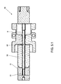
Figs. 5.1 and5.2 show representative schemes of the press jaw in the apparatus forming stages illustrated inFig. 1 ; -
Fig. 6 is an enlarged detail view of dimension control stage of the apparatus illustrated inFig. 1 ; and -
Figs. 7.1 ,7.2 and 7.3 are examples of connecting tubes formed in the apparatus illustrated inFig. 1 . - The invention will be described in detail based on the attached drawings, containing reference numerals, for a better comprehension.
- An
apparatus 100 for forming connecting tubes, in accordance with the invention, is shown inFig. 1 which depicts one of its preferred embodiments, wherein it is possible to note that the same is composed of several stages, each of them configuring the die (or blank) which will form the final product or connecting tube depicted inFigs. 7.1 ,7.2 and 7.3 . Thus, upon driving drill bits, punctures and dies commanded as specified by the design of the workpieces to be formed, connectingtubes 6 provided with reductions indiameter 61 andflanges 52 are produced. - In the preferred embodiment of the invention as illustrated in
Fig. 1 , theapparatus 100 comprises fivestages Figs. 2 to 6 . It should be pointed that optionally saidapparatus 100 can be composed of double stages, that is, 10 stages, for example, such that there would comprise five pairs of stages, wherein such flexible possibility allows for a significant increase in the production rate and/or also permit to create arrangements for the simultaneous manufacture of two or more different products in one single apparatus. This is possible due to the fact that it refers to an apparatus having ten stages, wherein five of them can be parameterized to a product having determined features whereas the other five stages are parameterized to have distinct final features, thus rendering a highly versatile production. Further, it is worth to say that, as previously mentioned, the apparatus can be produced with only four stages, i.e., having only one forming stage (30 or 40). - Generally, the
apparatus 100 for forming connectingtubes 6 is connected to a hydraulic system comprising amotor 2 andelements 3 which are responsible for the operation of many production stages, wherein near saidapparatus 100 there is amodule 4 at which twovibratory pans 5 are disposed for storing copper or steel tubes to be formed, wherein saidvibratory pans 5 cooperate with a conveyor belt 11. - It should be clear that over a surface or table 7 on which several production stages are disposed, there will be disposed at least one
longitudinal trail 8 wherebyclaws 9, which can be automated, convey the tubes between the several production stages such that at no moment in the production process human interference is required and, therefore, process acceleration and process safety are enhanced. - According to a preferred embodiment of the invention, the first production stage, that is,
feed stage 10 that is illustrated in detail inFig. 2 , comprises an individualized raw material feed system; in this case thetube 6 had already been cut in the required dimension. Such individualization is preferably, but not limitative, carried out by means of vibratory pans which can be operated in synchronism with a conveyor belt 11, thereby releasing thetubes 6 in a specific position to be further conveyed. - As can be observed in more detail from
Fig. 3 , in thedeburring stage 20 the reaming process takes place to remove burrs from the cut of tube 6 (or blank) formerly conducted by other apparatus (not shown). To this effect, same is placed betweensupport 21 anddrill bits 22 driven bydrills 23 moving toward, by sliding ontrails 24, theedges 63 of saidtube 6 such that saiddrill bits 22, in rotary movement, remove the material and form chamfers on said edges 63. - In the
product deburring stage 30, as illustrated inFig. 5.1 , there is the formation ofreductions 61 andflange 62. To this effect,tube 6 which had been processed in thedeburring stage 20 is conveyed with the aid ofclaw 9 to the formingstage 30 wherein it is forced to pass through a die 31 having a diameter corresponding to diameter required in thereduction region 61. Thus, by means of forward movement, saidtube 6 rests on the bottom ofdie 31 and the material is forced to retrieve, filling another die 32 to a shape corresponding to flange 62. - Therefore, it is noted that said forming
stage 30 of theapparatus 100 forms in one sole step thereduction 61 andflange 62 of the connectingtube 6, in a significantly more rapid, effective and practical way than that of the state of the art. - Therefore, the
production deburring stage 30 comprises at least a tube securing system and at least a tool - die (31, 32) and/or puncture element (41) - , wherein such tool has a profile corresponding to the profile of the connectingtube 6 at which one of the sides is formed. Depending on the product features, there can be provided a second tool serving to form the opposite side of the connectingtube 6. Said tools are movable and replaceable by other tools having distinct dimensional features. Furthermore, depending on the product or raw material features there may be necessary to implant at least one additional stage with features similar to that of the formingstage 30, aiming at the final profile of the product in question. - Next, said
tube 6 being formed is sent to flange formingstage 40 illustrated inFig. 5.2 in which through a process involving the puncture element (41) of thetube 6 and its driving toward theedge 63A corresponding to the reduction edge, a chamfer is formed. - At the
opposite edge 63 oftube 6, the expanding operation can be optionally conducted, where it is formed by advancing asecond puncture element 42 having a diameter corresponding to the outer diameter of the expanded tube, also by a die 43 corresponding to the outer diameter of the expandedtube 6, wherein a clearance is added. - By this way, passing the connecting
tube 6 trough theflange forming stage 40 is an indication of the end of the forming process, and the next step comprises a new stage, that is,dimensional control stage 50 shown in detail inFig. 6 , where the previously formedtube 6 is measured to control the diameter offlange 62. It should be pointed out that, to this effect,claw 9 collects thetube 6 from the die of theflange forming stage 40 and sends it to be positioned into abipartite cavity 51 having an inner diameter corresponding to the outer diameter of flange 82 oftube 6. Thus, saidtube 6 is positioned, theactuator 52 is driven such that thebipartite cavity 51 closes, and after such closing a strategically positioned sensor system sends collected information to a measurement column programmed with possible variation limits for the connectingtube 6. In the case that the product dimensions do not fulfill the predetermined specifications, an electronic signal is sent to the apparatus controller and the workpiece is discarded and thrown by theclaw 9 or by other suitable means onto a discard tray or similar compartment. - Analogously, in the case that the product dimensions meet the required and accepted specifications, the product is sent to a storage place.
- It should be emphasized that another patent application was filed and assigned to the same owner as the one of the present patent application to claim patent protection for said
stage 50, which separately comprises the dimensional control system for connecting tubes. - Further, it should be clarified that the main advantages of the present invention reside in the capacity of forming
reduction 61 andflan 62 in one same production stage in a practically simultaneous mode, thus significantly optimizing the product process, thereby providing a produced volume much higher than that obtained by known similar apparatuses at the same period of time. - Another advantage refers to the flexible possibility of producing two or more connecting tubes having different features in a
single apparatus 100 by simple replacement ofpuncture elements - Finally, it should be herein assured that the highest technological gain of said
apparatus 100 disclosed herein is the possibility of manufacturing the final product in a large scale production, which is capable of meeting demand of hermetic compressor manufacturers. - It should be emphasized that although the preferred embodiments of the present invention have been shown, it is to be understood that eventual omissions, substitutions, electric pole inversion, and construction modifications can be made by a person skilled in the art without departing from the spirit and claimed scope of protection. It is also expressly predicted that all combinations of elements that perform the same function substantially in the same form to achieve the same results are within the scope of the invention. Substitutions of elements of a described embodiment by others are also fully intended and contemplated.
Claims (10)
- Apparatus for forming connecting tubes, wherein said apparatus (100) is interconnected with an electric system comprising at least a motor (2) and control means (3) and a modulus (4), at which at least one reservoir is disposed for storing tubes (6) to be formed in reduction regions (61) and flanges (62), said apparatus being CHARACTERIZED in that it comprises:at least a surface (7) on which at least four production stages (10, 20, 30 or 40, and 50) are disposed;said at least four production stages comprise a feed stage (10), a deburring or reaming stage (20), at least one forming stage - forming reduction stage (30) and/or flange forming stage (40) and a dimensional control stage (50);many production stages (10, 20, 30 ou 40 and 50) are interconnected with at least a longitudinal trail(8) on which at least four claws (9) slide;at the end of the process, in the case that the dimensions of the connecting tube (6) do not meet the predetermined specifications, an electronic signal is sent to a control element (3) of the apparatus (100) and said tube (6) is discarded.
- Apparatus, in accordance with claim 1, CHARACTERIZED in that the feed stage (10) comprises at least one vibratory pan (5) cooperating with a conveyor (11).
- Apparatus, in accordance with claim 1, CHARACTERIZED in that said deburring stage (20) comprise support elements (21) and drill bits (22) driven by drills (23) which, sliding on axes (24) moves toward the edges (63) of the connecting tubes (6) such that the drill bits (22) in a rotary movement remove the material and form chamfers or grooves on said edges.
- Apparatus, in accordance with claim 1, CHARACTERIZED in that the forming stage (3) comprises at least a tube securing system and at least one tool selected from a die (31, 32) and a puncture element (41), wherein said at least one tool (31, 31, 41) has a profile corresponding to the profile of said connecting tube (6) to form one of the sides of said connecting tube (6).
- Apparatus, in accordance with claim 4, CHARACTERIZED in that said die (31) has a diameter corresponding to the diameter required for the reduction region (61) of said connecting tube (6), and the die (32) acts on forming the flange (62).
- Apparatus, in accordance with claims 4 and 5, CHARACTERIZED in that said at least two dies (31, 32) are movable and replaceable by other dies having different dimensional features.
- Apparatus, in accordance with claim 1, CHARACTERIZED in that the dimensional control stage (50) comprises at least one bipartite cavity (51) having an inner diameter corresponding to the outer diameter of the flange (62) of said connecting tube (6), wherein said at least one bipartite cavity (52) cooperates with a sensor system and a measurement column programmed with the possible variation limits for the connecting tube (6).
- Apparatus, in accordance with claim 1, CHARACTERIZED in that said apparatus (100) comprises at least four double stages (10, 20, 30 or 40 and 50) so as to comprise 8 stages for simultaneous production of connecting tubes (6) having distinct features.
- Apparatus for forming connecting tubes, CHARACTERIZED in that it comprises means for forming reductions (61) and flanges (62) of connecting tubes (6) in a single and simultaneous production step.
- Process for forming connecting tubes, CHARACTERIZED in that it comprises an apparatus as defined in any of claims 1 to 5 for carrying out the following steps:- individually and sequentially positioning the connecting tube (6) through a continuously sequential feed, aligned by the length of the connecting tube (6) through a vibratory pan (5) and conveyor belt (11), making the connecting tube (6) ready for further handling;- conveying the connecting tube (6) from the feed stage (20) to the deburring stage by means of at least one claw (9) sliding on at least one longitudinal trail (8);- displacing the drill bits (22) driven by drills by sliding on the axes (24) toward the edges (63, 63A) of the connecting tube (6) such that said drill bits (22), in rotary movement, remove burrs and form chamfers or grooves on said edges (63) of said tube (6);- conveying the connecting tube (6) from the deburring stage (20) to the forming stage (30) by means of a claw (9) sliding on at least one longitudinal trail (8);- applying force to cause the connecting tube (6) to pass by a die (31) having a diameter corresponding to the diameter required for the forming region (61) such that through a forward movement said connecting tube (6) rests on the bottom of the die (31) and the material is forced to retrieve, filling other die (32) with a shape corresponding to the flange;- additionally, depending on the profile defined on the product, the connecting tube (6) passes through a second puncture tool or die tool to alter the profile of the opposite tip of the connecting tube (6);- conveying the connecting tube (6) from the forming stage (30) to the flange forming stage (40) by means of the at least one claw (9) sliding on the at least one longitudinal trail (8);- forming a chamfer on the edge (63A) of the connecting tube (6) through a puncture element (41) driven toward the edge (63A) corresponding to the reduction edge;- carrying out an optional expansion operation for the opposite edge (63) of the connecting tube (6), comprising moving forward a second puncture element (42) having a diameter corresponding to the outer diameter of the expanded tube, also by a die (43) corresponding to the outer diameter of the expanded connecting tube (6);- conveying the connecting tube (6) from the flange forming stage (40) to the dimensional control stage (50) by means of said at least one claw (9) sliding on said at least one longitudinal trail (8);- positioning the connecting tube (6) into a bipartite cavity (51) having an inner diameter corresponding to the outer diameter of the flange (62) of the tube (6);- driving the actuator (52) such that the bipartite cavity (51) closes, wherein after such closing a sensor system sends collected information to a measurement column programmed with the possible variation limits for the connecting tube (6);- in the case that the product dimensions do not fulfill predetermined specifications, an electronic signal is sent to the apparatus controller and the connecting tube (6) is discarded and thrown by the automated claw or by other suitable device to a discard tray or similar compartment;- in the case that the product dimensions fulfill the required and accepted specifications, the ready connecting tube is sent to a storage place.
Applications Claiming Priority (2)
| Application Number | Priority Date | Filing Date | Title |
|---|---|---|---|
| BRPI1228903 | 2012-11-12 | ||
| PCT/BR2013/000478 WO2014071488A1 (en) | 2012-11-12 | 2013-11-07 | Equipment for shaping connector tubes |
Publications (2)
| Publication Number | Publication Date |
|---|---|
| EP2781816A1 true EP2781816A1 (en) | 2014-09-24 |
| EP2781816A4 EP2781816A4 (en) | 2015-11-04 |
Family
ID=51356368
Family Applications (1)
| Application Number | Title | Priority Date | Filing Date |
|---|---|---|---|
| EP13853031.6A Withdrawn EP2781816A4 (en) | 2012-11-12 | 2013-11-07 | Equipment for shaping connector tubes |
Country Status (1)
| Country | Link |
|---|---|
| EP (1) | EP2781816A4 (en) |
Cited By (1)
| Publication number | Priority date | Publication date | Assignee | Title |
|---|---|---|---|---|
| IT202200015924A1 (en) * | 2022-07-27 | 2024-01-27 | Gnutti Transfer S P A | Apparatus for mechanical processing by plastic deformation or for the assembly of a pair of components, and related machine tool comprising such apparatus. |
Family Cites Families (4)
| Publication number | Priority date | Publication date | Assignee | Title |
|---|---|---|---|---|
| FR1496155A (en) * | 1966-06-29 | 1967-09-29 | Processes for manufacturing tubes fitted with beads and assembling these tubes | |
| JPH02207925A (en) * | 1989-02-06 | 1990-08-17 | Kiyousan Denki Kk | Multi-stage deforming device for hollow pipe |
| US5211046A (en) * | 1989-02-06 | 1993-05-18 | Kyosan Denki Kabushiki Kaisha | Method for forming multistage hollow pipe |
| DE3937888A1 (en) * | 1989-11-15 | 1991-05-16 | Bundy Gmbh | PIPE CONNECTION |
-
2013
- 2013-11-07 EP EP13853031.6A patent/EP2781816A4/en not_active Withdrawn
Cited By (2)
| Publication number | Priority date | Publication date | Assignee | Title |
|---|---|---|---|---|
| IT202200015924A1 (en) * | 2022-07-27 | 2024-01-27 | Gnutti Transfer S P A | Apparatus for mechanical processing by plastic deformation or for the assembly of a pair of components, and related machine tool comprising such apparatus. |
| EP4311608A1 (en) * | 2022-07-27 | 2024-01-31 | Gnutti Transfer S.p.A. | Apparatus for mechanical machining by plastic deformation or for assembling a pair of components, and relative machine tool comprising such an apparatus |
Also Published As
| Publication number | Publication date |
|---|---|
| EP2781816A4 (en) | 2015-11-04 |
Similar Documents
| Publication | Publication Date | Title |
|---|---|---|
| JP5688593B2 (en) | Method and apparatus for manufacturing twist drill or screw in metal elongated member with spiral groove | |
| CN111036831B (en) | Automatic forging system and method for ring gear blank | |
| CA2134741A1 (en) | Process for manufacturing surgical needles | |
| CN111283186B (en) | Sintered body manufacturing apparatus and sintered body manufacturing method | |
| JP2008264871A (en) | Method for manufacturing member with flange | |
| WO2009120397A1 (en) | Method of producing a stepped shaft | |
| KR20050058994A (en) | Methods for the cold extrusion of metallic elements with dead or through holes and plant for carrying out said methods | |
| US8215880B2 (en) | Servo motor for actuating a mandrel while extruding helical teeth | |
| EP2781816A1 (en) | Equipment for shaping connector tubes | |
| US8807001B2 (en) | Penetrator and method of manufacturing same | |
| US9669449B2 (en) | Method for producing a through hole in a metallic body | |
| EP2952270A1 (en) | Punch machine with sheet metal roll feed | |
| MX2014008076A (en) | Equipment for shaping connector tubes. | |
| US10654092B2 (en) | Method and apparatus for manufacturing stepped member | |
| CN105050750A (en) | Method for producing blind vias in metal bodies | |
| JP2016117101A (en) | Net shape forging for fluid end and other work-pieces | |
| CN107639421A (en) | A kind of discharge process equipment and its processing technology | |
| JP6096051B2 (en) | Manufacturing method of outer joint member for constant velocity universal joint, intermediate forged product and final forged product processed into outer joint member | |
| CN101193726A (en) | Progressive die tooling method and apparatus | |
| CN105033055B (en) | Automobile front-axle support manufacture continuous mould and manufacture method | |
| US9821368B2 (en) | Method for producing a cylindrical component | |
| US20180126432A1 (en) | Composite manufacturing method with extruding and turning processes | |
| EP2520404A1 (en) | Procedure for the construction of thermoforming moulds | |
| JP3203284U (en) | Horizontal multi-stage forging machine | |
| RU2595182C1 (en) | Device for production of cylindrical billets in the form of a glass |
Legal Events
| Date | Code | Title | Description |
|---|---|---|---|
| PUAI | Public reference made under article 153(3) epc to a published international application that has entered the european phase |
Free format text: ORIGINAL CODE: 0009012 |
|
| 17P | Request for examination filed |
Effective date: 20140616 |
|
| AK | Designated contracting states |
Kind code of ref document: A1 Designated state(s): AL AT BE BG CH CY CZ DE DK EE ES FI FR GB GR HR HU IE IS IT LI LT LU LV MC MK MT NL NO PL PT RO RS SE SI SK SM TR |
|
| AX | Request for extension of the european patent |
Extension state: BA ME |
|
| R17P | Request for examination filed (corrected) |
Effective date: 20141029 |
|
| RBV | Designated contracting states (corrected) |
Designated state(s): AL AT BE BG CH CY CZ DE DK EE ES FI FR GB GR HR HU IE IS IT LI LT LU LV MC MK MT NL NO PL PT RO RS SE SI SK SM TR |
|
| RA4 | Supplementary search report drawn up and despatched (corrected) |
Effective date: 20151006 |
|
| RIC1 | Information provided on ipc code assigned before grant |
Ipc: F16L 19/02 20060101ALI20150930BHEP Ipc: F16L 13/14 20060101AFI20150930BHEP Ipc: B21D 35/00 20060101ALI20150930BHEP Ipc: B21C 37/28 20060101ALI20150930BHEP |
|
| DAX | Request for extension of the european patent (deleted) | ||
| 17Q | First examination report despatched |
Effective date: 20170906 |
|
| STAA | Information on the status of an ep patent application or granted ep patent |
Free format text: STATUS: THE APPLICATION IS DEEMED TO BE WITHDRAWN |
|
| 18D | Application deemed to be withdrawn |
Effective date: 20180117 |