EP2520404A1 - Procedure for the construction of thermoforming moulds - Google Patents
Procedure for the construction of thermoforming moulds Download PDFInfo
- Publication number
- EP2520404A1 EP2520404A1 EP12166892A EP12166892A EP2520404A1 EP 2520404 A1 EP2520404 A1 EP 2520404A1 EP 12166892 A EP12166892 A EP 12166892A EP 12166892 A EP12166892 A EP 12166892A EP 2520404 A1 EP2520404 A1 EP 2520404A1
- Authority
- EP
- European Patent Office
- Prior art keywords
- moulds
- thermoforming
- procedure
- construction
- channels
- Prior art date
- Legal status (The legal status is an assumption and is not a legal conclusion. Google has not performed a legal analysis and makes no representation as to the accuracy of the status listed.)
- Granted
Links
Images
Classifications
-
- B—PERFORMING OPERATIONS; TRANSPORTING
- B29—WORKING OF PLASTICS; WORKING OF SUBSTANCES IN A PLASTIC STATE IN GENERAL
- B29C—SHAPING OR JOINING OF PLASTICS; SHAPING OF MATERIAL IN A PLASTIC STATE, NOT OTHERWISE PROVIDED FOR; AFTER-TREATMENT OF THE SHAPED PRODUCTS, e.g. REPAIRING
- B29C51/00—Shaping by thermoforming, i.e. shaping sheets or sheet like preforms after heating, e.g. shaping sheets in matched moulds or by deep-drawing; Apparatus therefor
- B29C51/26—Component parts, details or accessories; Auxiliary operations
- B29C51/30—Moulds
- B29C51/36—Moulds specially adapted for vacuum forming, Manufacture thereof
-
- B—PERFORMING OPERATIONS; TRANSPORTING
- B29—WORKING OF PLASTICS; WORKING OF SUBSTANCES IN A PLASTIC STATE IN GENERAL
- B29C—SHAPING OR JOINING OF PLASTICS; SHAPING OF MATERIAL IN A PLASTIC STATE, NOT OTHERWISE PROVIDED FOR; AFTER-TREATMENT OF THE SHAPED PRODUCTS, e.g. REPAIRING
- B29C33/00—Moulds or cores; Details thereof or accessories therefor
- B29C33/10—Moulds or cores; Details thereof or accessories therefor with incorporated venting means
-
- B—PERFORMING OPERATIONS; TRANSPORTING
- B29—WORKING OF PLASTICS; WORKING OF SUBSTANCES IN A PLASTIC STATE IN GENERAL
- B29C—SHAPING OR JOINING OF PLASTICS; SHAPING OF MATERIAL IN A PLASTIC STATE, NOT OTHERWISE PROVIDED FOR; AFTER-TREATMENT OF THE SHAPED PRODUCTS, e.g. REPAIRING
- B29C33/00—Moulds or cores; Details thereof or accessories therefor
- B29C33/38—Moulds or cores; Details thereof or accessories therefor characterised by the material or the manufacturing process
- B29C33/3842—Manufacturing moulds, e.g. shaping the mould surface by machining
-
- B—PERFORMING OPERATIONS; TRANSPORTING
- B29—WORKING OF PLASTICS; WORKING OF SUBSTANCES IN A PLASTIC STATE IN GENERAL
- B29C—SHAPING OR JOINING OF PLASTICS; SHAPING OF MATERIAL IN A PLASTIC STATE, NOT OTHERWISE PROVIDED FOR; AFTER-TREATMENT OF THE SHAPED PRODUCTS, e.g. REPAIRING
- B29C51/00—Shaping by thermoforming, i.e. shaping sheets or sheet like preforms after heating, e.g. shaping sheets in matched moulds or by deep-drawing; Apparatus therefor
- B29C51/26—Component parts, details or accessories; Auxiliary operations
- B29C51/30—Moulds
- B29C51/40—Venting means
Definitions
- This invention relates to a procedure for the construction of moulds designed for the thermoforming of plastic materials.
- the present invention refers to a procedure which uses thermoforming moulds manufactured with a technology which is new to this sector: laser technology.
- the procedure according to the present invention proposes plastic injection moulds which have a system of air vent channels which follow the geometry of the texture and which in this specific example follow pyramidal shapes as far as their tips and connect the pyramids to each other.
- These channels comprise a grid inside the texture connected to side gutter channels which permit the correct escape of air from the mould.
- the present invention can be applied in the mechanical engineering industry for the moulding of plastic materials and in particular applies to the sector for moulds used for the thermoforming primarily, but not exclusively, of plastic materials.
- thermoforming moulding sector produces moulded parts starting out from sheets of plastic material of various thickness which are placed in moulds and then heated so that they adhere to the walls of the mould and thereby take on the shape required.
- moulds In general the industrial production processes of moulding, die-casting, deep drawing, foaming and sintering require moulds to shape the parts or the materials being processed. These moulds comprise dies designed specifically as forming tools.
- the main components of moulds are usually two or more half-moulds or dies containing the shape of the part to be produced.
- Production moulds are usually made from hardened and tempered steel or tempered steel (the result of heat treatment processes used to improve the characteristics of metals); for special processes aluminium or wooden moulds may be used.
- Industrial moulds can be used for the production of single parts, small series of multiple parts or for hundreds of thousands of parts.
- Medium to large size moulds are usually manufactured by milling on machine tools.
- Particularly small moulds with complex finishes or those requiring a high degree of precision (to a few hundredths of a millimetre) are produced using electrical discharge machining, photoengraving and, the most recent development, laser technology.
- thermoforming plastics consists of processing sheets of heated plastic which are placed on top of the mould which is frequently a single, male die.
- a pneumatic vacuum is then created under the mould and through special holes in the mould assists adherence and draws the material onto the mould where it solidifies.
- moulds usually economic given that they do not require resistances or temperatures and can be made from wood, resin or soft metals. They can be used to manufacture parts of a considerable size (up to several metres) using moulds of a suitable size.
- thermoforming has evident limits when it has to be used for moulding complex geometries and three-dimensional textures.
- thermoforming processes The main limitation of known thermoforming processes is the difficulty of discharging the air from the mould. This is particularly the case when the mould has a complex texture because not all the air is able to escape from the mould and pockets of air are created which prevent the creation of the texture.
- the present invention concerns a procedure for the construction of moulds designed for the thermoforming of plastic materials which makes it possible to eliminate or at least reduce the drawbacks described above.
- This invention also relates to a procedure for the construction of moulds designed for the thermoforming of plastic materials which is simple to implement.
- thermoforming moulds in addition to all those which derive from its simple, easy to manufacture design, primarily concern that fact that the procedure for making thermoforming moulds according to the invention employs laser technology - a technology which is new to this sector.
- the procedure according to the present invention proposes plastic injection moulds which have a system of air vent channels which follow the geometry of the texture and which in this specific example follow pyramidal shapes as far as their tips and connect the pyramids to each other.
- These channels comprise a grid inside the texture connected to side gutter channels which permit the correct escape of air from the mould.
- the procedure according to the present invention involves the use of plastic injection moulds 10 with a system of air vent channels 11, formed by laser cutting, which follow the geometry of the texture of the surface of the moulded article.
- this texture has, for example, a pyramidal shape
- the vent channels 11 specific to this application will follow the pyramid shapes to their tips and then connect to the other pyramids.
- These channels comprise a grid or network inside the texture and are connected to side gutter channels 12 which permit the efficient escape of air from the mould.
- the side gutter channels 12 in turn are connected to a master vent hole 13 through which the air escapes to the outside of the mould.
- This solution can be managed directly in the workshop thereby avoiding the need for the traditional operations to create the holes in the mould or to construct the mould with a costly material.
- the solution simply uses a system of side gutter channels 12 combined with a series of air circulating channels 11.
- Design Rendering Engineering (D.R.E. ® ) which makes it possible to design the system of channels on the geometric texture chosen by the customer.
Abstract
Description
- This invention relates to a procedure for the construction of moulds designed for the thermoforming of plastic materials.
- In particular the present invention refers to a procedure which uses thermoforming moulds manufactured with a technology which is new to this sector: laser technology.
- The procedure according to the present invention proposes plastic injection moulds which have a system of air vent channels which follow the geometry of the texture and which in this specific example follow pyramidal shapes as far as their tips and connect the pyramids to each other.
- These channels comprise a grid inside the texture connected to side gutter channels which permit the correct escape of air from the mould.
- These channels are so small that they do not deform the plastic material which will line the mould during moulding but at the same time are large enough to permit the air to escape from the mould.
- The present invention can be applied in the mechanical engineering industry for the moulding of plastic materials and in particular applies to the sector for moulds used for the thermoforming primarily, but not exclusively, of plastic materials.
- It is well known that the thermoforming moulding sector produces moulded parts starting out from sheets of plastic material of various thickness which are placed in moulds and then heated so that they adhere to the walls of the mould and thereby take on the shape required.
- In general the industrial production processes of moulding, die-casting, deep drawing, foaming and sintering require moulds to shape the parts or the materials being processed. These moulds comprise dies designed specifically as forming tools.
- Mould characteristics and technology vary according to the type of process.
- The main components of moulds are usually two or more half-moulds or dies containing the shape of the part to be produced.
- Production moulds are usually made from hardened and tempered steel or tempered steel (the result of heat treatment processes used to improve the characteristics of metals); for special processes aluminium or wooden moulds may be used.
- Industrial moulds can be used for the production of single parts, small series of multiple parts or for hundreds of thousands of parts. Medium to large size moulds are usually manufactured by milling on machine tools. Particularly small moulds with complex finishes or those requiring a high degree of precision (to a few hundredths of a millimetre) are produced using electrical discharge machining, photoengraving and, the most recent development, laser technology.
- The process for thermoforming plastics consists of processing sheets of heated plastic which are placed on top of the mould which is frequently a single, male die.
- A pneumatic vacuum is then created under the mould and through special holes in the mould assists adherence and draws the material onto the mould where it solidifies.
- These types of mould are usually economic given that they do not require resistances or temperatures and can be made from wood, resin or soft metals. They can be used to manufacture parts of a considerable size (up to several metres) using moulds of a suitable size.
- The known method of thermoforming has evident limits when it has to be used for moulding complex geometries and three-dimensional textures.
- The known procedure for moulding by thermoforming consists of two main steps:
- 1. Creation of a vacuum and the application of a sheet of plastic material over the mould to prevent the passage of air.
- 2. Evacuation of the air contained inside the mould by sucking out the air through micro-holes (attached to special suction devices) which are dimensioned and positioned so that they do not leave marks on the finished product.
- The main limitation of known thermoforming processes is the difficulty of discharging the air from the mould. This is particularly the case when the mould has a complex texture because not all the air is able to escape from the mould and pockets of air are created which prevent the creation of the texture.
- The search for a solution to overcome the problem of evacuating all the air from the mould has lead to the following solutions. ML believes that both solutions present considerable problems:
- a) Thermoforming processing with plastic sheets which have already been textured by embossing. In this case process times are increased because the sheet has to be separately textured before it is placed in the thermoforming mould in a subsequent step.
Furthermore, the main problem is the deformation of the texture which takes place when a flat sheet is placed over and lines a three-dimensional mould. The texture in this case depends very much on the shape of the mould. - b) Porous nickel moulds. This material is chosen for the construction of moulds because its characteristics enable the evacuation of the air from the mould. In this case the costs of making the mould itself are very high and the time needed to produce the mould are very long.
- Some companies have proposed another solution as follows.
- c) The creation of holes on all the apices of the pyramids forming the texture. However, these holes enabling the air to escape have to be drilled through the entire thickness of the mould. This particular solution is too expensive in terms of both times and costs in that it requires the use of a very costly machine tool with the capability of drilling through a steel mould.
- The present invention concerns a procedure for the construction of moulds designed for the thermoforming of plastic materials which makes it possible to eliminate or at least reduce the drawbacks described above.
- This invention also relates to a procedure for the construction of moulds designed for the thermoforming of plastic materials which is simple to implement.
- This purpose is achieved by a procedure for the construction of moulds for the thermoforming of plastic materials with the characteristics described in the main claim.
- The dependent claims of the solution in question describe advantageous embodiments of the invention.
- The principal advantages of this solution, in addition to all those which derive from its simple, easy to manufacture design, primarily concern that fact that the procedure for making thermoforming moulds according to the invention employs laser technology - a technology which is new to this sector.
- The procedure according to the present invention proposes plastic injection moulds which have a system of air vent channels which follow the geometry of the texture and which in this specific example follow pyramidal shapes as far as their tips and connect the pyramids to each other.
- These channels comprise a grid inside the texture connected to side gutter channels which permit the correct escape of air from the mould.
- These channels are so small that they do not deform the plastic material which will line the mould during moulding but at the same time are large enough to permit the air to escape from the mould.
- Further features and advantages of the invention will become apparent from the description of an embodiment which follows with reference to the annexed drawings, given purely by way of a non-limiting example, in which:
-
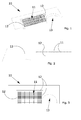
Figure 1 shows a diagram of one possible configuration of the air vent channels for thermoforming; -
Figure 2 shows a cross-section of an aspiration channel connected to the master aspiration channel; -
Figure 3 shows a plan view of a possible configuration of the aspiration channels, the master channels and the master aspiration hole according to the invention as a whole. - The annexed figures illustrate a procedure for the construction of moulds designed for the thermoforming of plastic material which substantially involves the use of thermoforming moulds indicated in their entirety by the
number 10 where the inside part of these moulds has been shaped employing laser technology. - As indicated above the procedure according to the present invention involves the use of
plastic injection moulds 10 with a system ofair vent channels 11, formed by laser cutting, which follow the geometry of the texture of the surface of the moulded article. - In the case where this texture has, for example, a pyramidal shape, the
vent channels 11 specific to this application will follow the pyramid shapes to their tips and then connect to the other pyramids. - These channels comprise a grid or network inside the texture and are connected to
side gutter channels 12 which permit the efficient escape of air from the mould. - These
channels 11 are so small that they do not deform the plastic material which will line the mould during moulding but at the same time are large enough to permit the air to escape from the mould. - The
side gutter channels 12 in turn are connected to amaster vent hole 13 through which the air escapes to the outside of the mould. - This solution can be managed directly in the workshop thereby avoiding the need for the traditional operations to create the holes in the mould or to construct the mould with a costly material. The solution simply uses a system of
side gutter channels 12 combined with a series ofair circulating channels 11. - This solution is made possible by Design Rendering Engineering (D.R.E.®) which makes it possible to design the system of channels on the geometric texture chosen by the customer.
- The procedure according to the present invention enables the achievement of significant advantages including:
- a) a high quality texture cut directly onto the mould;
- b) absence of the traditional problems of stretching and deformation found with the embossing-thermoforming system;
- c) the possibility of customising thermoformed items by operating directly on the mould; decorations chosen by the customer can be positioned precisely on the mould;
- d) the possibility of reducing production times and costs;
- e) the possibility of creating any type of three-dimensional texture on surfaces with a complex geometry thanks to the D.R.E.® system which makes it possible to redesign the channel system to match any texture.
- The invention is described above with reference to a preferred embodiment. It is nevertheless clear that the invention is susceptible to numerous variations which lie within the scope of its disclosure and within the framework of technical equivalents.
Claims (7)
- A procedure for the construction of moulds designed for the thermoforming of plastic materials, characterised in that it uses thermoforming moulds (10), these moulds being shaped, that is to say internally notched, by means of laser technology in order to create a plurality of microchannels (11) which flow into a plurality of side gutter channels (12) for the air, connected in turn to a master vent hole (13), from which the air escapes towards the outside of the mould.
- The procedure for the construction of moulds for the thermoforming of plastic materials according to the foregoing claim, characterised in that for the injection of plastic material it uses said moulds (10) provided with a system of air vent microchannels (11) made by laser incision, which follow the geometry of the texture of the surface of the moulded article.
- The procedure for the construction of moulds for the thermoforming of plastic materials according to either of the foregoing claims, characterised in that if the said texture is created with pyramidal type shapes, the specific vent channels (11) follow these pyramidal type shapes as far as their tip and connect the pyramids to each other.
- The procedure for the construction of moulds for the thermoforming of plastic materials according to any of the foregoing claims, characterised in that said channels (11) form a grid inside the texture, connected to the side gutter channels (12), which allow the correct escape of the air.
- The procedure for the construction of moulds for the thermoforming of plastic materials according to any of the foregoing claims, characterised in that said channels (11) have such a limited thickness as to not in turn deform the plastic material which lines the mould, but are sufficient to allow the air to escape.
- The procedure for the construction of moulds for the thermoforming of plastic materials according to any of the foregoing claims, characterised in that the side gutter channels (12) are in turn connected to a master vent hole (13), from which the air escapes outside the mould.
- The procedure for the construction of moulds for the thermoforming of plastic materials according to any of the foregoing claims, characterised in that the laser processing of said microchannels is performed by means of a D.R.E.® Design Rendering Engineering type system, with which it is possible to design the system of channels on the geometrical texture.
Applications Claiming Priority (1)
| Application Number | Priority Date | Filing Date | Title |
|---|---|---|---|
| IT000094A ITVR20110094A1 (en) | 2011-05-06 | 2011-05-06 | PROCEDURE FOR THE REALIZATION OF MOLDS FOR THERMOFORMING |
Publications (2)
| Publication Number | Publication Date |
|---|---|
| EP2520404A1 true EP2520404A1 (en) | 2012-11-07 |
| EP2520404B1 EP2520404B1 (en) | 2018-02-21 |
Family
ID=44554410
Family Applications (1)
| Application Number | Title | Priority Date | Filing Date |
|---|---|---|---|
| EP12166892.5A Active EP2520404B1 (en) | 2011-05-06 | 2012-05-04 | Procedure for the construction of thermoforming moulds |
Country Status (3)
| Country | Link |
|---|---|
| EP (1) | EP2520404B1 (en) |
| IT (1) | ITVR20110094A1 (en) |
| PT (1) | PT2520404T (en) |
Cited By (1)
| Publication number | Priority date | Publication date | Assignee | Title |
|---|---|---|---|---|
| IT201900010977A1 (en) * | 2019-07-05 | 2021-01-05 | Ml Engraving S R L | Gasket, mold, laser machine, method of making said mold, method of making said gasket |
Citations (4)
| Publication number | Priority date | Publication date | Assignee | Title |
|---|---|---|---|---|
| US6660216B1 (en) * | 1998-12-14 | 2003-12-09 | Conix Corporation | Methods and apparatus for blow molding using micrograined patterns |
| DE102005037308A1 (en) * | 2005-08-04 | 2007-02-08 | Werkzeugbau Siegfried Hofmann Gmbh | Deaerated mold, e.g. injection mold or casting mold, has deaeration device consisting of laser-generated deaerating grooves of defined cross-sectional shape and/or area in mold separation plane region |
| US20080191390A1 (en) * | 2007-02-08 | 2008-08-14 | Denso Corporation | Method of producing molding die for use in producing a ceramic honeycomb structure body |
| EP2098349A1 (en) * | 2006-12-01 | 2009-09-09 | Tanazawa Hakkosha Co., Ltd. | Mold for resin molding, method for manufacturing mold for resin molding, and resin molded product |
-
2011
- 2011-05-06 IT IT000094A patent/ITVR20110094A1/en unknown
-
2012
- 2012-05-04 PT PT121668925T patent/PT2520404T/en unknown
- 2012-05-04 EP EP12166892.5A patent/EP2520404B1/en active Active
Patent Citations (4)
| Publication number | Priority date | Publication date | Assignee | Title |
|---|---|---|---|---|
| US6660216B1 (en) * | 1998-12-14 | 2003-12-09 | Conix Corporation | Methods and apparatus for blow molding using micrograined patterns |
| DE102005037308A1 (en) * | 2005-08-04 | 2007-02-08 | Werkzeugbau Siegfried Hofmann Gmbh | Deaerated mold, e.g. injection mold or casting mold, has deaeration device consisting of laser-generated deaerating grooves of defined cross-sectional shape and/or area in mold separation plane region |
| EP2098349A1 (en) * | 2006-12-01 | 2009-09-09 | Tanazawa Hakkosha Co., Ltd. | Mold for resin molding, method for manufacturing mold for resin molding, and resin molded product |
| US20080191390A1 (en) * | 2007-02-08 | 2008-08-14 | Denso Corporation | Method of producing molding die for use in producing a ceramic honeycomb structure body |
Cited By (1)
| Publication number | Priority date | Publication date | Assignee | Title |
|---|---|---|---|---|
| IT201900010977A1 (en) * | 2019-07-05 | 2021-01-05 | Ml Engraving S R L | Gasket, mold, laser machine, method of making said mold, method of making said gasket |
Also Published As
| Publication number | Publication date |
|---|---|
| ITVR20110094A1 (en) | 2012-11-07 |
| EP2520404B1 (en) | 2018-02-21 |
| PT2520404T (en) | 2018-05-08 |
Similar Documents
| Publication | Publication Date | Title |
|---|---|---|
| CN106181243B (en) | The processing method of car light mould bases | |
| US20140238097A1 (en) | Laminated cavity tooling | |
| EP2520404A1 (en) | Procedure for the construction of thermoforming moulds | |
| CN207547418U (en) | One kind prevents the corrugated drawing die in part | |
| CN207043833U (en) | A kind of interior star-wheel die vent locating and machining block | |
| CN204710978U (en) | The mould of apparatus housing of taking action for processing and forming one | |
| CN210589671U (en) | Stamping die for plastic product processing | |
| CN206085510U (en) | Mold processing of backplate | |
| CN105397991A (en) | Blow-molding die capable of automatically punching within die | |
| CN207240916U (en) | High-pressure resin Transfer molding mould | |
| JP4798139B2 (en) | Forging apparatus and forging method | |
| CN205989385U (en) | Carpet water cutting machine blanking die | |
| CN105945653B (en) | A kind of cutting dies of shop parts inner edge | |
| CN206393795U (en) | A kind of compound backward and forward extrusion mould with water cooling tube | |
| CN205833936U (en) | A kind of thick material fine blanking die | |
| CN205071501U (en) | Integrated into one piece's metal -back implantation laminating device is moulded to heat | |
| CN203844079U (en) | Novel mould | |
| CN104386486B (en) | The pneumatic system of automatic clamping casing can be realized | |
| CN215703992U (en) | Mould is used in production of plastics burette | |
| CN103331844A (en) | Mold for manufacturing rubber products and machining method thereof | |
| CN207547427U (en) | A kind of stamping die | |
| CN207941844U (en) | A kind of multi-angle repaiies stamping die | |
| CN107856281A (en) | Drawn a design technique for thermoplastic articles processing and forming plastic uptake | |
| CN208558161U (en) | A kind of fast demoulding mold | |
| CN215472480U (en) | Membrane inner-pasting wire drawing die |
Legal Events
| Date | Code | Title | Description |
|---|---|---|---|
| PUAI | Public reference made under article 153(3) epc to a published international application that has entered the european phase |
Free format text: ORIGINAL CODE: 0009012 |
|
| AK | Designated contracting states |
Kind code of ref document: A1 Designated state(s): AL AT BE BG CH CY CZ DE DK EE ES FI FR GB GR HR HU IE IS IT LI LT LU LV MC MK MT NL NO PL PT RO RS SE SI SK SM TR |
|
| AX | Request for extension of the european patent |
Extension state: BA ME |
|
| 17P | Request for examination filed |
Effective date: 20130507 |
|
| 17Q | First examination report despatched |
Effective date: 20150616 |
|
| GRAP | Despatch of communication of intention to grant a patent |
Free format text: ORIGINAL CODE: EPIDOSNIGR1 |
|
| RIC1 | Information provided on ipc code assigned before grant |
Ipc: B29C 33/42 20060101ALI20170921BHEP Ipc: B29C 51/36 20060101ALI20170921BHEP Ipc: B29C 51/40 20060101ALI20170921BHEP Ipc: B29C 33/38 20060101AFI20170921BHEP Ipc: B29C 33/10 20060101ALI20170921BHEP Ipc: B23P 15/24 20060101ALN20170921BHEP |
|
| INTG | Intention to grant announced |
Effective date: 20171011 |
|
| GRAS | Grant fee paid |
Free format text: ORIGINAL CODE: EPIDOSNIGR3 |
|
| GRAA | (expected) grant |
Free format text: ORIGINAL CODE: 0009210 |
|
| AK | Designated contracting states |
Kind code of ref document: B1 Designated state(s): AL AT BE BG CH CY CZ DE DK EE ES FI FR GB GR HR HU IE IS IT LI LT LU LV MC MK MT NL NO PL PT RO RS SE SI SK SM TR |
|
| REG | Reference to a national code |
Ref country code: GB Ref legal event code: FG4D |
|
| REG | Reference to a national code |
Ref country code: CH Ref legal event code: EP |
|
| REG | Reference to a national code |
Ref country code: AT Ref legal event code: REF Ref document number: 971218 Country of ref document: AT Kind code of ref document: T Effective date: 20180315 |
|
| REG | Reference to a national code |
Ref country code: IE Ref legal event code: FG4D |
|
| REG | Reference to a national code |
Ref country code: DE Ref legal event code: R096 Ref document number: 602012042940 Country of ref document: DE |
|
| REG | Reference to a national code |
Ref country code: PT Ref legal event code: SC4A Ref document number: 2520404 Country of ref document: PT Date of ref document: 20180508 Kind code of ref document: T Free format text: AVAILABILITY OF NATIONAL TRANSLATION Effective date: 20180502 |
|
| REG | Reference to a national code |
Ref country code: FR Ref legal event code: PLFP Year of fee payment: 7 |
|
| REG | Reference to a national code |
Ref country code: NL Ref legal event code: MP Effective date: 20180221 |
|
| REG | Reference to a national code |
Ref country code: LT Ref legal event code: MG4D |
|
| REG | Reference to a national code |
Ref country code: AT Ref legal event code: MK05 Ref document number: 971218 Country of ref document: AT Kind code of ref document: T Effective date: 20180221 |
|
| PG25 | Lapsed in a contracting state [announced via postgrant information from national office to epo] |
Ref country code: FI Free format text: LAPSE BECAUSE OF FAILURE TO SUBMIT A TRANSLATION OF THE DESCRIPTION OR TO PAY THE FEE WITHIN THE PRESCRIBED TIME-LIMIT Effective date: 20180221 Ref country code: NO Free format text: LAPSE BECAUSE OF FAILURE TO SUBMIT A TRANSLATION OF THE DESCRIPTION OR TO PAY THE FEE WITHIN THE PRESCRIBED TIME-LIMIT Effective date: 20180521 Ref country code: CY Free format text: LAPSE BECAUSE OF FAILURE TO SUBMIT A TRANSLATION OF THE DESCRIPTION OR TO PAY THE FEE WITHIN THE PRESCRIBED TIME-LIMIT Effective date: 20180221 Ref country code: HR Free format text: LAPSE BECAUSE OF FAILURE TO SUBMIT A TRANSLATION OF THE DESCRIPTION OR TO PAY THE FEE WITHIN THE PRESCRIBED TIME-LIMIT Effective date: 20180221 Ref country code: NL Free format text: LAPSE BECAUSE OF FAILURE TO SUBMIT A TRANSLATION OF THE DESCRIPTION OR TO PAY THE FEE WITHIN THE PRESCRIBED TIME-LIMIT Effective date: 20180221 Ref country code: LT Free format text: LAPSE BECAUSE OF FAILURE TO SUBMIT A TRANSLATION OF THE DESCRIPTION OR TO PAY THE FEE WITHIN THE PRESCRIBED TIME-LIMIT Effective date: 20180221 Ref country code: ES Free format text: LAPSE BECAUSE OF FAILURE TO SUBMIT A TRANSLATION OF THE DESCRIPTION OR TO PAY THE FEE WITHIN THE PRESCRIBED TIME-LIMIT Effective date: 20180221 |
|
| PG25 | Lapsed in a contracting state [announced via postgrant information from national office to epo] |
Ref country code: GR Free format text: LAPSE BECAUSE OF FAILURE TO SUBMIT A TRANSLATION OF THE DESCRIPTION OR TO PAY THE FEE WITHIN THE PRESCRIBED TIME-LIMIT Effective date: 20180522 Ref country code: AT Free format text: LAPSE BECAUSE OF FAILURE TO SUBMIT A TRANSLATION OF THE DESCRIPTION OR TO PAY THE FEE WITHIN THE PRESCRIBED TIME-LIMIT Effective date: 20180221 Ref country code: SE Free format text: LAPSE BECAUSE OF FAILURE TO SUBMIT A TRANSLATION OF THE DESCRIPTION OR TO PAY THE FEE WITHIN THE PRESCRIBED TIME-LIMIT Effective date: 20180221 Ref country code: LV Free format text: LAPSE BECAUSE OF FAILURE TO SUBMIT A TRANSLATION OF THE DESCRIPTION OR TO PAY THE FEE WITHIN THE PRESCRIBED TIME-LIMIT Effective date: 20180221 Ref country code: BG Free format text: LAPSE BECAUSE OF FAILURE TO SUBMIT A TRANSLATION OF THE DESCRIPTION OR TO PAY THE FEE WITHIN THE PRESCRIBED TIME-LIMIT Effective date: 20180521 Ref country code: RS Free format text: LAPSE BECAUSE OF FAILURE TO SUBMIT A TRANSLATION OF THE DESCRIPTION OR TO PAY THE FEE WITHIN THE PRESCRIBED TIME-LIMIT Effective date: 20180221 |
|
| PG25 | Lapsed in a contracting state [announced via postgrant information from national office to epo] |
Ref country code: PL Free format text: LAPSE BECAUSE OF FAILURE TO SUBMIT A TRANSLATION OF THE DESCRIPTION OR TO PAY THE FEE WITHIN THE PRESCRIBED TIME-LIMIT Effective date: 20180221 Ref country code: AL Free format text: LAPSE BECAUSE OF FAILURE TO SUBMIT A TRANSLATION OF THE DESCRIPTION OR TO PAY THE FEE WITHIN THE PRESCRIBED TIME-LIMIT Effective date: 20180221 Ref country code: RO Free format text: LAPSE BECAUSE OF FAILURE TO SUBMIT A TRANSLATION OF THE DESCRIPTION OR TO PAY THE FEE WITHIN THE PRESCRIBED TIME-LIMIT Effective date: 20180221 Ref country code: EE Free format text: LAPSE BECAUSE OF FAILURE TO SUBMIT A TRANSLATION OF THE DESCRIPTION OR TO PAY THE FEE WITHIN THE PRESCRIBED TIME-LIMIT Effective date: 20180221 |
|
| REG | Reference to a national code |
Ref country code: DE Ref legal event code: R097 Ref document number: 602012042940 Country of ref document: DE |
|
| PG25 | Lapsed in a contracting state [announced via postgrant information from national office to epo] |
Ref country code: CZ Free format text: LAPSE BECAUSE OF FAILURE TO SUBMIT A TRANSLATION OF THE DESCRIPTION OR TO PAY THE FEE WITHIN THE PRESCRIBED TIME-LIMIT Effective date: 20180221 Ref country code: SM Free format text: LAPSE BECAUSE OF FAILURE TO SUBMIT A TRANSLATION OF THE DESCRIPTION OR TO PAY THE FEE WITHIN THE PRESCRIBED TIME-LIMIT Effective date: 20180221 Ref country code: DK Free format text: LAPSE BECAUSE OF FAILURE TO SUBMIT A TRANSLATION OF THE DESCRIPTION OR TO PAY THE FEE WITHIN THE PRESCRIBED TIME-LIMIT Effective date: 20180221 Ref country code: SK Free format text: LAPSE BECAUSE OF FAILURE TO SUBMIT A TRANSLATION OF THE DESCRIPTION OR TO PAY THE FEE WITHIN THE PRESCRIBED TIME-LIMIT Effective date: 20180221 |
|
| REG | Reference to a national code |
Ref country code: CH Ref legal event code: PL |
|
| PLBE | No opposition filed within time limit |
Free format text: ORIGINAL CODE: 0009261 |
|
| STAA | Information on the status of an ep patent application or granted ep patent |
Free format text: STATUS: NO OPPOSITION FILED WITHIN TIME LIMIT |
|
| 26N | No opposition filed |
Effective date: 20181122 |
|
| REG | Reference to a national code |
Ref country code: BE Ref legal event code: MM Effective date: 20180531 |
|
| PG25 | Lapsed in a contracting state [announced via postgrant information from national office to epo] |
Ref country code: MC Free format text: LAPSE BECAUSE OF FAILURE TO SUBMIT A TRANSLATION OF THE DESCRIPTION OR TO PAY THE FEE WITHIN THE PRESCRIBED TIME-LIMIT Effective date: 20180221 |
|
| REG | Reference to a national code |
Ref country code: IE Ref legal event code: MM4A |
|
| PG25 | Lapsed in a contracting state [announced via postgrant information from national office to epo] |
Ref country code: LI Free format text: LAPSE BECAUSE OF NON-PAYMENT OF DUE FEES Effective date: 20180531 Ref country code: CH Free format text: LAPSE BECAUSE OF NON-PAYMENT OF DUE FEES Effective date: 20180531 Ref country code: SI Free format text: LAPSE BECAUSE OF FAILURE TO SUBMIT A TRANSLATION OF THE DESCRIPTION OR TO PAY THE FEE WITHIN THE PRESCRIBED TIME-LIMIT Effective date: 20180221 |
|
| PG25 | Lapsed in a contracting state [announced via postgrant information from national office to epo] |
Ref country code: LU Free format text: LAPSE BECAUSE OF NON-PAYMENT OF DUE FEES Effective date: 20180504 |
|
| PG25 | Lapsed in a contracting state [announced via postgrant information from national office to epo] |
Ref country code: IE Free format text: LAPSE BECAUSE OF NON-PAYMENT OF DUE FEES Effective date: 20180504 |
|
| PG25 | Lapsed in a contracting state [announced via postgrant information from national office to epo] |
Ref country code: BE Free format text: LAPSE BECAUSE OF NON-PAYMENT OF DUE FEES Effective date: 20180531 |
|
| PGFP | Annual fee paid to national office [announced via postgrant information from national office to epo] |
Ref country code: FR Payment date: 20190531 Year of fee payment: 8 |
|
| PGFP | Annual fee paid to national office [announced via postgrant information from national office to epo] |
Ref country code: GB Payment date: 20190521 Year of fee payment: 8 |
|
| PG25 | Lapsed in a contracting state [announced via postgrant information from national office to epo] |
Ref country code: MT Free format text: LAPSE BECAUSE OF NON-PAYMENT OF DUE FEES Effective date: 20180504 |
|
| PG25 | Lapsed in a contracting state [announced via postgrant information from national office to epo] |
Ref country code: TR Free format text: LAPSE BECAUSE OF FAILURE TO SUBMIT A TRANSLATION OF THE DESCRIPTION OR TO PAY THE FEE WITHIN THE PRESCRIBED TIME-LIMIT Effective date: 20180221 |
|
| PG25 | Lapsed in a contracting state [announced via postgrant information from national office to epo] |
Ref country code: HU Free format text: LAPSE BECAUSE OF FAILURE TO SUBMIT A TRANSLATION OF THE DESCRIPTION OR TO PAY THE FEE WITHIN THE PRESCRIBED TIME-LIMIT; INVALID AB INITIO Effective date: 20120504 |
|
| PG25 | Lapsed in a contracting state [announced via postgrant information from national office to epo] |
Ref country code: MK Free format text: LAPSE BECAUSE OF NON-PAYMENT OF DUE FEES Effective date: 20180221 |
|
| PG25 | Lapsed in a contracting state [announced via postgrant information from national office to epo] |
Ref country code: IS Free format text: LAPSE BECAUSE OF FAILURE TO SUBMIT A TRANSLATION OF THE DESCRIPTION OR TO PAY THE FEE WITHIN THE PRESCRIBED TIME-LIMIT Effective date: 20180621 |
|
| GBPC | Gb: european patent ceased through non-payment of renewal fee |
Effective date: 20200504 |
|
| PG25 | Lapsed in a contracting state [announced via postgrant information from national office to epo] |
Ref country code: GB Free format text: LAPSE BECAUSE OF NON-PAYMENT OF DUE FEES Effective date: 20200504 Ref country code: FR Free format text: LAPSE BECAUSE OF NON-PAYMENT OF DUE FEES Effective date: 20200531 |
|
| PGFP | Annual fee paid to national office [announced via postgrant information from national office to epo] |
Ref country code: PT Payment date: 20230420 Year of fee payment: 12 Ref country code: IT Payment date: 20230405 Year of fee payment: 12 Ref country code: DE Payment date: 20230519 Year of fee payment: 12 |