EP2781702A1 - Thermodynamic work machine - Google Patents
Thermodynamic work machine Download PDFInfo
- Publication number
- EP2781702A1 EP2781702A1 EP13160291.4A EP13160291A EP2781702A1 EP 2781702 A1 EP2781702 A1 EP 2781702A1 EP 13160291 A EP13160291 A EP 13160291A EP 2781702 A1 EP2781702 A1 EP 2781702A1
- Authority
- EP
- European Patent Office
- Prior art keywords
- hollow shaft
- hollow
- work machine
- machine according
- working
- Prior art date
- Legal status (The legal status is an assumption and is not a legal conclusion. Google has not performed a legal analysis and makes no representation as to the accuracy of the status listed.)
- Withdrawn
Links
Images


Classifications
-
- F—MECHANICAL ENGINEERING; LIGHTING; HEATING; WEAPONS; BLASTING
- F01—MACHINES OR ENGINES IN GENERAL; ENGINE PLANTS IN GENERAL; STEAM ENGINES
- F01L—CYCLICALLY OPERATING VALVES FOR MACHINES OR ENGINES
- F01L7/00—Rotary or oscillatory slide valve-gear or valve arrangements
- F01L7/02—Rotary or oscillatory slide valve-gear or valve arrangements with cylindrical, sleeve, or part-annularly shaped valves
- F01L7/026—Rotary or oscillatory slide valve-gear or valve arrangements with cylindrical, sleeve, or part-annularly shaped valves with two or more rotary valves, their rotational axes being parallel, e.g. 4-stroke
Definitions
- the invention relates to a thermodynamic working machine for operation with a gaseous working medium having the features of the preamble of claim 1.
- Thermodynamic machines within the meaning of the invention, that is to say machines which perform mechanical work with a working medium or make use of mechanical work, have been known for a long time and in many variants.
- Such machines typically have an expansion space into which a working fluid is introduced and in which it undergoes a volumetric expansion.
- movable means are arranged, which are moved in the volume expansion of the working medium and at which the mechanically useful work is performed.
- combustion engines in which a combustible gas mixture in the expansion space, there also referred to as a combustion chamber, is admitted and ignited there. During the combustion of the gas mixture, an abrupt increase in volume occurs, which drives the mechanical element in the working space.
- cylindrical combustion chambers are known here with arranged therein, up and down moving piston. These cylindrical combustion chambers have inlet and outlet valves in order, on the one hand, to allow the mixture to be combusted to flow into the cylinder, and on the other hand to allow the exhaust gases produced during the combustion to flow out and drain off.
- inlet and outlet are often closed with so-called poppet valves, which are operated clocked by a camshaft.
- the poppet valves on the inlet side can be omitted in injection engines.
- an inflammable fuel-air mixture is injected directly into the combustion chamber and then ignited.
- the discharge of the combustion gases is also there in the usual way by opening a valve, in particular poppet valve.
- valve forms for the control of internal combustion engines or for the admission of the combustion mixture and exhaust of the exhaust gases are known.
- the DD 146198 an encircling valve arrangement in the form of a rotating shaft with holes bored radially therethrough, which bores establish a connection between a feed line of the combustion mixture and the inlet into the combustion cylinder or, on the outlet side, a connection between the outlet of the cylinder and an exhaust pipe.
- the arrangement in the internal combustion engine shown in this publication is a series arrangement of a plurality, there four, cylinders, which are arranged so that a first continuous shaft, the inlet control, a second continuous shaft, the exhaust control operated.
- valve sections of the shaft which are assigned to each of the cylinders, are separated from each other. Inflowing fuel-air mixture can pass through the inlets controlling shaft only in the respective associated cylinder, a flow path to adjacent cylinders is closed. The same applies on the downstream side, where exhaust gas flowing out of a cylinder is transmitted only to the respective associated exhaust gas channel or the exhaust gas line.
- thermodynamic machines which do not use a combustion of a fuel-air mixture for the performance of mechanical work due to the resulting volume expansion, but a volume expansion at a phase transition of the working medium, in particular a phase transition from the liquid to the gaseous phase.
- the working fluid is heated so far that it is above the phase transition temperature between the liquid and the gas phase at a predetermined pressure, the resulting gas is introduced with expansion in the expansion space and there performs mechanical work on the movable element, in the case of a cylinder as an expansion space the piston, in the case of a vane motor, for example, on the sliders of the individual cell spaces.
- thermodynamic machines that exploit volume expansion during a phase transition can be guided in a closed circuit (eg as RANKINE circulating motors) or in an open medium guide, eg operated with water vapor, which exits into the environment after expansion work has been carried out.
- a RANKINE circulatory device in the form of a vane motor operated with a closed loop working fluid is disclosed in US Pat DE 601 23 987 T2 shown.
- the corresponding RANKINE cycle device is described as an auxiliary unit to an internal combustion engine to increase by additional mechanical work that performs this unit, the efficiency of the combined arrangement over the efficiency of a pure internal combustion engine.
- the invention is concerned with such considerations and aims to provide a simply designed, simply constructed and reliable thermodynamic working machine that can be operated by a working medium utilizing the volumetric expansion in the phase transition, especially in the closed circuit.
- thermodynamic machine with the features of claim 1.
- Advantageous developments of this machine are specified in the dependent claims 2 to 10.
- the thermodynamic working machine set up or provided for operation with a gaseous working medium has at least two cylinders each having a working piston which is movable therein. These cylinders each have an inlet and an outlet.
- the work machine has a first valve arrangement for opening and closing the inlets and a second valve arrangement for opening and closing the outlets.
- the second valve assembly includes a sealed to its end faces, driven during operation of the machine for rotation about its longitudinal axis second hollow shaft arranged in its peripheral wall and opening into the lying within the second hollow shaft cavity through openings.
- the passage openings of the hollow shaft are arranged so that they can be connected upon rotation of the hollow shafts about their respective longitudinal axis with the inlets or the outlets of the cylinder to form a fürströmthetic.
- the cavity in the interior of each hollow shaft is in particular a continuous one, but at least passages are flow-connected to one another through a common cavity which come into communication with the inlets of different and adjacent cylinders.
- valve arrangements contain hollow shafts through which the working medium flows through the passage openings into the cylinders and work there, or in the case of the outlet valve shaft can flow out of the cylinders and be discharged, initially allowing a simple construction of the valve arrangements .
- poppet valves as they are often found in conventional internal combustion engines, no complicated driving mechanism in the form of a camshaft is provided for a valve arrangement according to the invention.
- spring arrangements are not required, get the closing of the valves. Overall, the mechanical structure is simplified and less fragmented.
- valve assemblies can with two (each one) get along hollow shafts, one of which all Inlets serving other outlets. Through the cavity in the first hollow shaft, the incoming working fluid can distribute evenly in the hollow shaft and build a uniform pressure before the respective through openings are released to the individual cylinders by the rotating hollow shaft.
- the design with the hollow shafts according to the invention is also particularly compact.
- this design allows the use of known from the field of internal combustion engine technology.
- internal combustion engines can be retrofitted with simple means and provided with the inventively provided valve arrangements with the hollow shafts.
- the cylinder heads are to be replaced in an array of cylinders in an internal combustion engine against corresponding valve assemblies connected to a cylinder head section with hollow shafts, the cylinder itself can be adopted without significant changes.
- Such retrofitting is not only possible in terms of a new building, in principle, even existing internal combustion engines can be converted accordingly to thermodynamic machines according to the invention with a few simple steps and with the result of a machine with high efficiency.
- a decentralized power supply e.g. existing and no longer used internal combustion engines used in the field of combined heat and power, are overhauled and rebuilt and then operated as thermodynamic working machines according to the invention, e.g. to drive electric generators.
- the passage openings are formed slot-shaped in the hollow shafts and have a longitudinal extent of the slot parallel to the longitudinal axis of the respective hollow shaft.
- Such a configuration ensures by the longitudinal extent of the slots that a sufficient cross-sectional area for a rapid influx of sufficient volume or stream of the expanding gaseous working medium into the cylinder or a discharge of the expanded and expanded working medium can be made from the cylinders.
- the slot width which can be chosen very targeted here, a very precise control of opening and closing time of the inlets or outlets of the cylinder, which is for achieving a smooth running and high efficiency of the machine of great importance.
- the passage openings are advantageously designed such that the passage openings of the first hollow shaft in the circumferential direction of the first hollow shaft having a small opening width than the seen in the circumferential direction of the second hollow shaft opening width of the passage openings of this second hollow shaft.
- the design can be, for example, such that it causes opening of the inlets in a position 10 ° before top dead center with respect to a rotational position of a connected via connecting rods with the piston crankshaft, the inlets closes at about 30 ° after top dead center, so that results in an opening interval in the interval of about 10 ° before top dead center to 30 ° after top dead center.
- the setting of the passage openings on the second hollow shaft can be designed, for example, so that the outlet opens with respect to the rotational position of the crankshaft at about 10 ° before bottom dead center and the outlets until shortly before the opening of the inlets, in this case to about 10th ° keeps open before top dead center.
- the working machine can be designed so that in the first and the second hollow shaft per cylinder two each with the inlet and the outlet of the respective cylinder during rotation of the respective hollow shaft cooperating through openings are provided in the peripheral wall of the hollow shaft which are diametrically opposed to each other.
- two work cycles that is to say periods of time in which expanding gas is conducted into the cylinder and mechanical work is performed, take place per entire revolution of the respective hollow shaft.
- a supply line for the pressurized and to be introduced into the cylinder, expanding gas may be arranged in a position opposite to the inlet, so that when the one of the passage openings opens the respective inlet of the cylinder, the diametrically opposite passage opening releases the supply line.
- an outflow line for expanded and expanded gaseous working medium may be provided in a position opposite the outlet, so that upon opening of the outlet by cooperation of the one passage opening with the outlet at the same time the passage opening opposite this passage opening for a connection to the discharge channel or discharge line releases.
- the valve arrangement of the working machine according to the invention is particularly simple if, as provided according to an advantageous development, the hollow shafts are rotatably arranged in a block sealed against the cylinders and have the inlets and the outlets sealed to the end faces. With sealed to the end faces here is a seal between the respective rotating hollow shaft and a receptacle in the block meant so that escape at this point no pressurized working fluid and thereby the efficiency of the machine can be reduced.
- Such a block can be easily produced on the one hand and forms on the other hand in addition to the storage of the hollow shafts and thus the design of the valve assembly at the same time the sealing of the cylinder in the upper section, so represents the cylinder head gasket.
- the inlet and outlet openings of the Cylinder be formed, which cooperate with the passage openings of the hollow shafts for the valve function.
- the working piston of the cylinder are connected via connecting rods with a crankshaft, which is driven in operation by the up and down movement of the working piston for rotation.
- the crankshaft can furthermore advantageously be coupled to the rotary drive of the hollow shafts with these hollow shafts with advantage.
- This coupling between the crankshaft and the hollow shafts may be formed such that a speed ratio between the crankshaft and the hollow shafts, i. each one of the hollow shafts, of 2: 1 yields.
- this coupling can take place such that the hollow shafts are coupled to one another via a coupling element for uniform rotation. This can be effected with advantage by a gear transmission which couples the hollow shafts with each other for opposite rotation at the same speed.
- thermodynamic machine is particularly suitable for operation with a guided in a closed circuit working fluid.
- the working machine is then advantageously connected to a closed circuit for the working medium.
- a work machine may e.g. be used to with the closed-cycle working medium waste heat from other processes, e.g. Waste heat from the combustion of fuels for the heat recovery or waste heat from industrial plants or waste heat from electric power plants are operated to continue to use this waste heat and to obtain mechanical energy, with the mechanical energy, for. to drive more electric generators.
- a setting of the working piston in the cylinders and the position of the arrangement of the passage openings in the hollow shafts is designed be that the different cylinders are running with different bars. So it is particularly appropriate here for a smooth running of the working machine, a first part, ideally half, of the cylinder in one working stroke to drive, while the second part, ideally the second half of the cylinder performs a cycle of discharging the relaxed working medium.
- the driving process performed in two cycles (venting the gas in the cylinder and causing work, expelling the expanded gaseous working fluid from the cylinders as the pistons move upwards) is carried out at any time on at least part of the cylinders, ideally halfway the cylinder is a power stroke, according to driving force on a piston downstream element, such as the crankshaft, is transmitted.
- thermodynamic machine 1 in the inventive design.
- This thermodynamic machine 1 has in a row arrangement a total of four cylindrical work spaces 2, in which pistons 3 are arranged movable up and down and sealed in the circumferential direction, as is well known for such machines.
- the pistons 3 are connected via connecting rods 4 with a crankshaft 5, which extends in a known manner cranked and together with the connecting rods 4 of the implementation of a linear movement of the piston 3 in a rotational movement, which executes the crankshaft 5 serves.
- the inlet valve arrangement comprises a hollow shaft 9, which is arranged in a valve block 6 and fits precisely into a shaft bearing 8 formed in the valve block 6, in which it can rotate.
- the hollow shaft 9 has in its interior a continuous cavity 10, the circumference by an outer wall 11 (see. Fig. 2 ) of the hollow shaft 9 is limited.
- the front side, the hollow shaft 9 is also closed. The manner in which this closure is carried out will be described below in particular with reference to the FIGS. 9 to 11 be explained in more detail.
- the hollow shaft 9 through openings 12 in the form of extending in the longitudinal direction of the hollow shaft 9 slots.
- the hollow shaft 9 at corresponding longitudinal positions of the hollow shaft 9 are arranged in each case diametrically opposite substantially identically shaped slots to slot pairs.
- the hollow shaft 9 in its outer wall 11 a total of four such pairs of slots.
- the diametral orientation of the two along the longitudinal extent of the hollow shaft 9 outboard slot pairs is the same.
- the two inwardly located with respect to the longitudinal extent of the hollow shaft 9 pairs of slots are also arranged the same in its diametrical orientation, but at 90 ° angularly offset from the orientations of each located to the axial ends of the hollow shaft 9 pairs of slots.
- the hollow shaft 9 in the rotational position shown there, the hollow shaft 9 is located in such a rotational position that the adjacent to the axial ends of the hollow shaft 9 through openings 12 on the one hand the supply 7 and on the other hand, an inlet opening 13 in the respective working space 2 of the outside aligned cylinder.
- working medium from the supply 7 flow into the cavity 10 of the hollow shaft 9 and penetrate from there into the respective working space 2 of the two outer cylinder and there the respective piston 3 in a in the Fig. 1 driving direction shown below.
- the continuous cavity 10 in the hollow shaft 9 can be through the various supply lines 7 (in principle, only a single supply line 7 may be provided here) flowing working medium spreads uniformly and is already inside the hollow shaft 9 at high pressure.
- the valve is opened to the associated working space 2 via the passage openings 12, which are brought into coincidence with corresponding inlet openings 13 of the associated working spaces 2, the working medium can flow into the working space over a short distance and already at full pressure and there with a high pressure Efficiency work.
- the pressure of the working medium, with which this is present in the supply line 7 and in the cavity 10 of the hollow shaft 9 is, for example, in the range of 10 bar.
- crankshaft 5 and the hollow shaft 9 are in the in Fig. 1 example shown coupled in a 1: 1 translation, ie they each run at the same rotational speed.
- the hollow shaft 9 diametrically opposite each other on its outer wall 11 has two passage openings 12, is fed at each half rotation of the hollow shaft 9 working fluid in the working space 2.
- This thermodynamic work machine thus operates on the two-stroke principle.
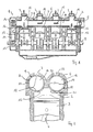
- Fig. 2 is in a cross section a section of the working machine 1 according to Fig. 1 shown.
- a second hollow shaft 18 is arranged in the valve block 6 in addition to the basis of Fig. 1 already described in more detail.
- This, too, has a continuous cavity 19 which is bounded on the circumference by an outer wall 20 of the hollow shaft 18.
- openings 21 are also provided, which are also formed slit-shaped and extending in the longitudinal direction of the hollow shaft 18. These openings 21 are located at diametrically opposite positions in the outer wall 20 of the hollow shaft 18.
- this hollow shaft 18 a total of four pairs of diametrically opposed passage openings 21 are arranged, in which case the respective axial end of the hollow shaft 18 adjacent pairs of each other opposing slot-shaped passage openings 21 in the same orientation, the intermediate pairs located therebetween are arranged at a 90 ° angle to this shifted alignment.
- the two hollow shafts 9 and 18 are oriented so that associated pairs of passage openings 12 and 21, which are associated with a working space 2, are arranged displaced by a 90 ° angle, as shown in FIG Fig. 2 easy to recognize.
- the shaft bearing 17 has a connection to a discharge line 22, which, when a corresponding passage opening 21 in the outer wall 20 of the hollow shaft 18 is opposite this, is released.
- an outlet opening 23 can be seen at the upper end of the working space 2, which can also be brought into coincidence with one of the passage openings 21 of the hollow shaft 18, so as to release an outlet from the working space 2.
- the second hollow shaft 28 is (not shown here) connected to the crankshaft 5 in a 1: 1 ratio to the rotary drive, so that it rotates at the same speed as the crankshaft 5 and also like the hollow shaft 18 in the shaft bearing 17.
- the passage openings 21 in the second hollow shaft 18 in the circumferential direction are formed wider (in the Fig. 2 only a schematic representation is given), so that sufficient time remains for the ejection process to free the working space 2 without a resistance of relaxed working medium.
- the width seen in the circumferential direction of the slot-shaped passage openings 12 in the hollow shaft 18 on the inlet valve side are kept small to cause here a sudden application of the working space 2 with pressurized working fluid with a short opening time.
- Fig. 3 It can be seen how the connection of the second hollow shaft 18 with the crankshaft 5 is accomplished.
- the first hollow shaft 18 is connected on one side with the toothed belt pulley 16, on the opposite side its second axial end is connected to a gear 24.
- This gear meshes with a gear 25 which is placed on the adjacent axial end of the second hollow shaft 18 and provided with the same toothing.
- a 1: 1 coupling of the two hollow shafts 9 and 18 is achieved.
- Fig. 4 is a view of the valve block 6 of the working spaces 2 facing bottom shown.
- the inlet openings 13 and outlet openings 23 which create a connection to the respective workrooms 2.
- a sealing groove 26 which encloses these openings in the closed course and in which a corresponding seal for sealing this area of the cylinder heads is introduced.
- the shaft bores 8 and 17 formed as cylinder bores for the hollow shaft 9 and 18 can be well seen.
- FIGS. 5 and 6 is in two different representations, once a longitudinal representation ( Fig. 5 ) and once a three-dimensional view obliquely from a front side once again the hollow shaft 18 of the exhaust valve assembly shown.
- the comparison with the similar representations of the hollow shaft 9 in the FIGS. 7 and 8 shows that in the hollow shaft 18, the slot-shaped passage openings 21 extend with a substantially larger width in the circumferential direction of the outer wall 20 for a correspondingly long-term controlled discharge time.
- FIGS. 7 and 8 are, as already mentioned, in the FIGS. 5 and 6 comparable representations, the hollow shaft 9 of the intake valve assembly shown again. Again, this hollow shaft 9 is shown without its axial ends occluding closing elements (end caps). Again, it can be clearly seen how the slot-shaped passage openings 12 are arranged in a staggered arrangement in pairs to each other in the outer wall 11 and introduced. The slot widths of the passage openings 12 seen in the circumferential direction are significantly smaller here than in the case of the hollow shaft 18, so that short inlet or control times can be achieved for the intake operation.
- FIGS. 9 and 10 are the hollow shafts 18 and 9 again shown in a side view with attached end caps 27 and 28 (with molded pins), which cause a closure of the end faces of the hollow shafts and thus completion of the cavities and on the other an arrangement of the gears or the To allow the toothed belt pulley on the pin and thus a transmission of the rotary drive.
- end caps 27 and 28 are in Fig. 11a or b again shown in an enlarged view.
Abstract
Description
Die Erfindung betrifft eine thermodynamische Arbeitsmaschine für den Betrieb mit einem gasförmigen Arbeitsmedium mit den Merkmalen des Oberbegriffes des Anspruches 1.The invention relates to a thermodynamic working machine for operation with a gaseous working medium having the features of the preamble of
Thermodynamische Arbeitsmaschinen, im Sinne der Erfindung, also solche Maschinen, die mit einem Arbeitsmedium betrieben mechanische Arbeit verrichten bzw. mechanische Arbeit nutzbar machen, sind seit langem und in vielen Varianten bekannt. Solche Arbeitsmaschinen weisen typischerweise einen Expansionsraum auf, in den ein Arbeitsmedium eingeleitet wird und in welchem dieses eine Volumenausdehnung erfährt. In dem Expansionsraum sind bewegbare Mittel angeordnet, die bei der Volumenausdehnung des Arbeitsmediums bewegt werden und an denen die mechanisch nutzbare Arbeit verrichtet wird.Thermodynamic machines, within the meaning of the invention, that is to say machines which perform mechanical work with a working medium or make use of mechanical work, have been known for a long time and in many variants. Such machines typically have an expansion space into which a working fluid is introduced and in which it undergoes a volumetric expansion. In the expansion space movable means are arranged, which are moved in the volume expansion of the working medium and at which the mechanically useful work is performed.
Bekannt sind insbesondere Verbrennungsmotoren, bei denen ein brennbares Gasgemisch in den Expansionsraum, dort auch als Verbrennungsraum zu bezeichnen, eingelassen und dort gezündet wird. Bei der Verbrennung des Gasgemisches entsteht eine schlagartige Volumenvergrößerung, die das mechanische Element in dem Arbeitsraum antreibt. Neben verschiedenen anderen Gestaltungsformen, wie z.B. Verbrennungsräumen in Rotationskolbenmotoren, sind hier insbesondere zylinderförmige Verbrennungsräume bekannt mit darin angeordneten, sich auf und ab bewegenden Kolben. Diese zylinderförmigen Verbrennungsräume besitzen Einlass- und Auslassventile, um einerseits das zu verbrennende Gemisch in den Zylinder einströmen zu lassen, andererseits die bei der Verbrennung entstehenden Abgase ausströmen zu lassen und abzuführen. Bei Verbrennungsmotoren sind Ein- und Auslass häufig mit sogenannten Tellerventilen verschlossen, die durch eine Nockenwelle getaktet betätigt werden. Die Tellerventile auf der Einlassseite können bei Einspritzmotoren entfallen. Dort wird ein entzündliches Brennstoff-Luftgemisch direkt in den Verbrennungsraum eingedüst und dann gezündet. Das Ablassen der Verbrennungsgase (Abgase) erfolgt jedoch auch dort in üblicher Weise mittels Öffnens eines Ventils, insbesondere Tellerventils.In particular, internal combustion engines are known, in which a combustible gas mixture in the expansion space, there also referred to as a combustion chamber, is admitted and ignited there. During the combustion of the gas mixture, an abrupt increase in volume occurs, which drives the mechanical element in the working space. In addition to various other forms of design, such as combustion chambers in rotary piston engines, in particular cylindrical combustion chambers are known here with arranged therein, up and down moving piston. These cylindrical combustion chambers have inlet and outlet valves in order, on the one hand, to allow the mixture to be combusted to flow into the cylinder, and on the other hand to allow the exhaust gases produced during the combustion to flow out and drain off. In internal combustion engines inlet and outlet are often closed with so-called poppet valves, which are operated clocked by a camshaft. The poppet valves on the inlet side can be omitted in injection engines. There, an inflammable fuel-air mixture is injected directly into the combustion chamber and then ignited. However, the discharge of the combustion gases (exhaust gases) is also there in the usual way by opening a valve, in particular poppet valve.
Neben den bekannten Tellerventilen sind auch andere Ventilformen für die Steuerung von Verbrennungsmotoren bzw. für das Einlassen des Verbrennungsgemisches und Ablassen der Abgase bekannt. So beschreibt beispielsweise die
Neben Verbrennungsmotoren existieren auch thermodynamische Arbeitsmaschinen, die nicht eine Verbrennung eines Brennstoff-Luftgemisches für die Verrichtung mechanischer Arbeit aufgrund der dabei entstehenden Volumenausdehnung nutzen, sondern eine Volumenausdehnung bei einem Phasenübergang des Arbeitsmediums, insbesondere einem Phasenübergang von der flüssigen in die gasförmige Phase. Dabei wird das Arbeitsmittel soweit erwärmt, dass es oberhalb der Phasenübergangstemperatur zwischen der flüssigen und der Gasphase bei einem vorbestimmten Druck liegt, das entstehende Gas wird unter Expansion in den Expansionsraum eingeleitet und verrichtet dort mechanische Arbeit an dem bewegbaren Element, im Falle eines Zylinders als Expansionsraum dem Kolben, im Falle eines Flügelzellenmotors z.B. an den Schiebern der einzelnen Zellenräume. Derartige die Volumenexpansion bei einem Phasenübergang ausnutzende thermodynamische Arbeitsmaschinen können in einem geschlossenen Kreislauf geführt werden (z.B. als RANKINE-Kreislaufmotoren), oder aber in einer offenen Mediumsführung, z.B. betrieben mit Wasserdampf, der nach geleisteter Expansionsarbeit in die Umgebung austritt. Ein Beispiel für eine RANKINE-Kreislaufvorrichtung in Form eines Flügelzellenmotors, der mit einem im geschlossenen Kreis geführten Arbeitsmedium betrieben wird, ist in der
So wie in der
Die Erfindung befasst sich mit solchen Erwägungen und hat zum Ziel, eine einfach gestaltete, einfach aufgebaute und zuverlässig arbeitende thermodynamische Arbeitsmaschine bereitzustellen, die von einem Arbeitsmedium unter Ausnutzung der Volumenausdehnung beim Phasenübergang betrieben werden kann, insbesondere auch im geschlossenen Kreislauf.The invention is concerned with such considerations and aims to provide a simply designed, simply constructed and reliable thermodynamic working machine that can be operated by a working medium utilizing the volumetric expansion in the phase transition, especially in the closed circuit.
Diese Aufgabe wird gelöst durch eine thermodynamische Arbeitsmaschine mit den Merkmalen des Anspruches 1. Vorteilhafte Weiterbildungen dieser Arbeitsmaschine sind in den abhängigen Ansprüchen 2 bis 10 angegeben.This object is achieved by a thermodynamic machine with the features of
Erfindungsgemäß weist die für den Betrieb mit einem gasförmigen Arbeitsmedium eingerichtete bzw. vorgesehene thermodynamische Arbeitsmaschine wenigstens zwei je einen darin bewegbaren Arbeitskolben aufweisende Zylinder auf. Diese Zylinder haben jeweils einen Einlass und einen Auslass. Die Arbeitsmaschine verfügt über eine erste Ventilanordnung zum Öffnen und Schließen der Einlässe sowie eine zweite Ventilanordnung zum Öffnen und Schließen der Auslässe. Das Besondere an dieser thermodynamischen Arbeitsmaschine gemäß der Erfindung ist nun, dass die erste Ventilanordnung eine zu ihren Stirnseiten hin abgedichtete, im Betrieb der Arbeitsmaschine zur Rotation um ihre Längsachse angetriebene erste Hohlwelle mit in ihrer Umfangswand angeordneten und in dem innerhalb der ersten Hohlwelle liegenden Hohlraum mündenden Durchtrittsöffnungen enthält. Weiterhin enthält gemäß der Erfindung die zweite Ventilanordnung eine zu ihren Stirnseiten hin abgedichtete, im Betrieb der Arbeitsmaschine zur Rotation um ihre Längsachse angetriebene zweite Hohlwelle mit in ihrer Umfangswand angeordneten und in dem innerhalb der zweiten Hohlwelle liegenden Hohlraum mündenden Durchtrittsöffnungen. Die Durchtrittsöffnungen der Hohlwelle sind dabei so angeordnet, dass sie bei Rotation der Hohlwellen um ihre jeweilige Längsachse mit den Einlässen bzw. den Auslässen der Zylinder zum Bilden einer Durchströmverbindung verbindbar sind. Hierbei ist der Hohlraum im Inneren einer jeden Hohlwelle insbesondere ein durchgehender, zumindest aber werden durch einen gemeinsamen Hohlraum Durchtrittsöffnungen miteinander strömungsverbunden, die mit den Einlässen verschiedener und benachbarter Zylinder in Verbindung geraten.According to the invention, the thermodynamic working machine set up or provided for operation with a gaseous working medium has at least two cylinders each having a working piston which is movable therein. These cylinders each have an inlet and an outlet. The work machine has a first valve arrangement for opening and closing the inlets and a second valve arrangement for opening and closing the outlets. The special feature of this thermodynamic machine according to the invention is now that the first valve assembly a sealed towards their end faces, driven during operation of the machine for rotation about its longitudinal axis first hollow shaft arranged in its peripheral wall and opening in the lying within the first hollow shaft cavity Passages contains. Furthermore, according to the invention, the second valve assembly includes a sealed to its end faces, driven during operation of the machine for rotation about its longitudinal axis second hollow shaft arranged in its peripheral wall and opening into the lying within the second hollow shaft cavity through openings. The passage openings of the hollow shaft are arranged so that they can be connected upon rotation of the hollow shafts about their respective longitudinal axis with the inlets or the outlets of the cylinder to form a Durchströmverbindung. In this case, the cavity in the interior of each hollow shaft is in particular a continuous one, but at least passages are flow-connected to one another through a common cavity which come into communication with the inlets of different and adjacent cylinders.
Diese erfindungsgemäße Ausgestaltung, wonach die Ventilanordnungen Hohlwellen enthalten, über die durch die Durchtrittsöffnungen hindurch das Arbeitsmedium in die Zylinder hinein strömen und dort Arbeit verrichten, bzw. im Falle der Auslassventilwelle aus den Zylindern ausströmen und abgeführt werden kann, erlaubt zunächst einen einfachen Aufbau der Ventilanordnungen. Anders als z.B. bei Tellerventilen, wie sie häufig bei herkömmlichen Verbrennungsmotoren zu finden sind, ist für eine erfindungsgemäße Ventilanordnung kein komplizierter Ansteuermechanismus in Form einer Nockenwelle vorzusehen. Darüber hinaus sind Federanordnungen nicht erforderlich, die das Schließen der Ventile besorgen. Insgesamt ist der mechanische Aufbau vereinfacht und weniger kleinteilig. Bei einer Anordnung der Zylinder in einer Reihe, wobei hier nicht nur zwei, sondern auch mehr Zylinder, beispielsweise vier, sechs oder auch mehr Zylinder in einer Reihenanordnung möglich sind, können die Ventilanordnungen mit zwei (je einer) Hohlwellen auskommen, von denen eine sämtliche Einlässe, die andere sämtliche Auslässe bedient. Durch den Hohlraum in der ersten Hohlwelle kann sich das einströmende Arbeitsmedium in der Hohlwelle gleichmäßig verteilen und einen einheitlich Druck aufbauen, bevor durch die rotierende Hohlwelle die jeweiligen Durchtrittsöffnungen zu den einzelnen Zylindern freigegeben werden. Wo bei dem Betrieb einer solchen Arbeitsmaschine als Verbrennungsmotor eine derartige gleichmäßige Verteilung eines Brennstoff-Luft-Gemisches abträglich und unerwünscht ist, führt eine derartige gleichmäßige Verteilung eines Arbeitsmediums bei einer wie hier betrachteten Arbeitsmaschine, die Volumenänderungen beim Phasenübergang insbesondere von flüssig zu gasförmig für die Umsetzung mechanischer Arbeit nutzt, zu einem besseren Ergebnis, zu einem besonders ruhigen Lauf der Arbeitsmaschine und auch zu einem hohen Wirkungsgrad. Denn dadurch, dass das expandierende Arbeitsmedium bereits mit hohem Druck im Hohlraum der Hohlwelle anliegt, kann dieses auf kürzestem Wege und eben bereits mit hohem Druck in den Arbeitsraum gelangen, dort unmittelbar mit hoher Wirkung Arbeit verrichten. Es muss nicht erst eine längere Strecke zwischen einer Zuleitung und dem eigentlichen Einlass des Arbeitsraumes überwunden und am Anfang eines Arbeitstaktes noch Druck aufgebaut werden.This embodiment according to the invention, according to which the valve arrangements contain hollow shafts through which the working medium flows through the passage openings into the cylinders and work there, or in the case of the outlet valve shaft can flow out of the cylinders and be discharged, initially allowing a simple construction of the valve arrangements , Unlike, for example, poppet valves, as they are often found in conventional internal combustion engines, no complicated driving mechanism in the form of a camshaft is provided for a valve arrangement according to the invention. In addition, spring arrangements are not required, get the closing of the valves. Overall, the mechanical structure is simplified and less fragmented. In an arrangement of the cylinder in a row, here not only two, but also more cylinders, for example, four, six or even more cylinders in a row arrangement are possible, the valve assemblies can with two (each one) get along hollow shafts, one of which all Inlets serving other outlets. Through the cavity in the first hollow shaft, the incoming working fluid can distribute evenly in the hollow shaft and build a uniform pressure before the respective through openings are released to the individual cylinders by the rotating hollow shaft. Where in the operation of such a machine as an internal combustion engine, such a uniform distribution of a fuel-air mixture is detrimental and undesirable, such a uniform distribution of a working medium in a working machine considered here, the volume changes during the phase transition in particular from liquid to gaseous for the implementation mechanical work, to a better result, to a particularly smooth running of the machine and also to a high efficiency. Because the fact that the expanding working fluid already rests with high pressure in the cavity of the hollow shaft, this can get on the shortest route and just at high pressure in the working space, where they work directly with high impact. It does not first have to overcome a longer distance between a supply line and the actual inlet of the working space and pressure is built up at the beginning of a work cycle.
Analoge Überlegungen gelten für die zweite Hohlwelle, bei der sich das aus den Zylindern abströmende, entspannte Arbeitsmedium ebenfalls im gesamten Hohlraum der Hohlwelle ausbreitet, insoweit besonders gut und vereinfacht abgeführt werden kann.Analogous considerations apply to the second hollow shaft, in which the discharged from the cylinders, relaxed working medium also propagates in the entire cavity of the hollow shaft, insofar as can be particularly good and simplified dissipated.
Die Bauform mit den erfindungsgemäßen Hohlwellen ist zudem besonders kompakt. Schließlich ermöglicht diese Bauform eine Nutzung von aus dem Bereich der Verbrennungsmotoren bekannter Motorentechnologie. So können beispielsweise Verbrennungsmotoren mit einfachen Mitteln umgerüstet und mit den erfindungsgemäß vorgesehenen Ventilanordnungen mit den Hohlwellen versehen werden. Hierzu sind lediglich die Zylinderköpfe in einer Reihenanordnung von Zylindern in einem Verbrennungsmotor auszutauschen gegen entsprechende mit einem Zylinderkopfabschnitt verbundene Ventilanordnungen mit Hohlwellen, die Zylinder an sich können ohne wesentliche Veränderungen so übernommen werden. Eine solche Umrüstung ist nicht nur hinsichtlich eines Neubaus möglich, grundsätzlich können sogar bestehende Verbrennungsmotoren entsprechend umgebaut werden zu erfindungsgemäßen thermodynamischen Arbeitsmaschinen mit wenigen Handgriffen und mit dem Ergebnis einer Arbeitsmaschine mit hohem Wirkungsgrad. Auf diese Weise können beispielsweise für eine dezentrale Energieversorgung z.B. im Bereich der Kraft-Wärme-Kopplung vorhandene und nicht mehr genutzte Verbrennungsmotoren eingesetzt, überholt und umgebaut werden und dann als thermodynamische Arbeitsmaschinen gemäß der Erfindung betrieben werden, z.B. zum Antrieb von elektrischen Generatoren.The design with the hollow shafts according to the invention is also particularly compact. Finally, this design allows the use of known from the field of internal combustion engine technology. For example, internal combustion engines can be retrofitted with simple means and provided with the inventively provided valve arrangements with the hollow shafts. For this purpose, only the cylinder heads are to be replaced in an array of cylinders in an internal combustion engine against corresponding valve assemblies connected to a cylinder head section with hollow shafts, the cylinder itself can be adopted without significant changes. Such retrofitting is not only possible in terms of a new building, in principle, even existing internal combustion engines can be converted accordingly to thermodynamic machines according to the invention with a few simple steps and with the result of a machine with high efficiency. In this way, for example, for a decentralized power supply, e.g. existing and no longer used internal combustion engines used in the field of combined heat and power, are overhauled and rebuilt and then operated as thermodynamic working machines according to the invention, e.g. to drive electric generators.
Mit Vorteil sind die Durchtrittsöffnungen in den Hohlwellen schlitzförmig gebildet und weisen eine Längserstreckung des Schlitzes parallel zur Längsachse der jeweiligen Hohlwelle auf. Eine solche Ausgestaltung stellt durch die Längserstreckung der Schlitze sicher, dass eine ausreichende Querschnittsfläche für ein schnelles Einströmen eines ausreichenden Volumens bzw. Stromes des expandierenden gasförmigen Arbeitsmediums in den Zylinder bzw. ein Ausströmen des expandierten und entspannten Arbeitsmediums aus den Zylindern erfolgen kann. Andererseits kann durch die Schlitzbreite, die hier sehr gezielt gewählt werden kann, eine sehr exakte Steuerung von Öffnungs- und Schließzeitpunkt der Einlässe bzw. Auslässe der Zylinder erfolgen, was für das Erreichen einer Laufruhe sowie eines hohen Wirkungsgrades der Arbeitsmaschine von großer Bedeutung ist.Advantageously, the passage openings are formed slot-shaped in the hollow shafts and have a longitudinal extent of the slot parallel to the longitudinal axis of the respective hollow shaft. Such a configuration ensures by the longitudinal extent of the slots that a sufficient cross-sectional area for a rapid influx of sufficient volume or stream of the expanding gaseous working medium into the cylinder or a discharge of the expanded and expanded working medium can be made from the cylinders. On the other hand, by the slot width, which can be chosen very targeted here, a very precise control of opening and closing time of the inlets or outlets of the cylinder, which is for achieving a smooth running and high efficiency of the machine of great importance.
Da typischerweise die Einlässe der Zylinder kürzere Öffnungszeiten für das schlagartige Befüllen mit dem expandierenden und unter Druck stehenden gasförmigen Arbeitsmedium erfordern, die Auslässe zum Ausstoßen des expandierten und entspannten Arbeitsmediums eine längere Öffnungszeit erfordern, sind mit vorteilhafter Weise die Durchtrittsöffnungen derart gestaltet, dass die Durchtrittsöffnungen der ersten Hohlwelle in der Umfangsrichtung der ersten Hohlwelle eine geringe Öffnungsweite aufweisen als die in Umfangsrichtung der zweiten Hohlwelle gesehene Öffnungsweite der Durchtrittsöffnungen dieser zweiten Hohlwelle. Die Gestaltung kann dabei beispielsweise derart sein, dass sie bezogen auf eine Drehstellung einer über Pleuelstangen mit den Kolben verbundenen Kurbelwelle ein Öffnen der Einlässe in eine Stellung 10° vor dem oberen Totpunkt bewirkt, die Einlässe bei etwa 30° nach dem oberen Totpunkt verschließt, so dass sich ein Öffnungsintervall im Intervall von etwa 10° vor dem oberen Totpunkt bis 30° nach dem oberen Totpunkt ergibt. Die Einstellung der Durchtrittsöffnungen an der zweiten Hohlwelle kann beispielsweise so gestaltet sein, dass die Auslassöffnungen bezogen auf die Drehstellung der Kurbelwelle bei etwa 10° vor dem unteren Totpunkt öffnet und die Auslässe bis kurz vor dem Öffnen der Einlässe, in diesem Fall also bis etwa 10° vor dem oberen Totpunkt offenhält.Since typically the inlets of the cylinders require shorter opening times for the sudden filling with the expanding and pressurized gaseous working fluid, the outlets for expelling the expanded and expanded working medium require a longer opening time, the passage openings are advantageously designed such that the passage openings of the first hollow shaft in the circumferential direction of the first hollow shaft having a small opening width than the seen in the circumferential direction of the second hollow shaft opening width of the passage openings of this second hollow shaft. The design can be, for example, such that it causes opening of the inlets in a
In einer weiteren vorteilhaften Weiterbildung der Erfindung kann die Arbeitsmaschine so gestaltet sein, dass in der ersten und der zweiten Hohlwelle je Zylinder jeweils zwei mit dem Einlass bzw. dem Auslass des jeweiligen Zylinders bei Rotation der jeweiligen Hohlwelle zusammenwirkende Durchtrittsöffnungen in der Umfangswand der Hohlwelle vorgesehen sind, die einander diametral gegenüberliegen. Dies führt dazu, dass pro ganzer Umdrehung der jeweiligen Hohlwelle zwei Arbeitstakte, also Zeitabschnitte, in denen expandierendes Gas in den Zylinder geleitet und mechanische Arbeit verrichtet wird, ablaufen. Zudem kann eine Zuführleitung für das unter Druck stehende und in die Zylinder einzuleitende, expandierende Gas in einer dem Einlass gegenüberliegenden Position angeordnet sein, so dass wenn die eine der Durchtrittsöffnungen den jeweiligen Einlass des Zylinders öffnet, die diametral gegenüberliegende Durchtrittsöffnung die Zuführleitung freigibt. Analog kann auf der Auslassseite eine Abströmleitung für expandiertes und entspanntes gasförmiges Arbeitsmedium in einer Position gegenüberliegend dem Auslass vorgesehen sein, so dass beim Öffnen des Auslasses durch Zusammenwirken der einen Durchtrittsöffnung mit dem Auslass zugleich die dieser Durchtrittsöffnung gegenüberliegende Durchtrittsöffnung für eine Verbindung zum Abströmkanal bzw. Abströmleitung freigibt.In a further advantageous embodiment of the invention, the working machine can be designed so that in the first and the second hollow shaft per cylinder two each with the inlet and the outlet of the respective cylinder during rotation of the respective hollow shaft cooperating through openings are provided in the peripheral wall of the hollow shaft which are diametrically opposed to each other. As a result, two work cycles, that is to say periods of time in which expanding gas is conducted into the cylinder and mechanical work is performed, take place per entire revolution of the respective hollow shaft. In addition, a supply line for the pressurized and to be introduced into the cylinder, expanding gas may be arranged in a position opposite to the inlet, so that when the one of the passage openings opens the respective inlet of the cylinder, the diametrically opposite passage opening releases the supply line. Analogously, on the outlet side, an outflow line for expanded and expanded gaseous working medium may be provided in a position opposite the outlet, so that upon opening of the outlet by cooperation of the one passage opening with the outlet at the same time the passage opening opposite this passage opening for a connection to the discharge channel or discharge line releases.
Besonders einfach ist die Ventilanordnung der erfindungsgemäßen Arbeitsmaschine aufgebaut, wenn, wie gemäß einer vorteilhaften Weiterbildung vorgesehen, die Hohlwellen in einem gegenüber den Zylindern abgedichteten, die Einlässe und die Auslässe aufweisenden Block rotierbar angeordnet und zu den Stirnseiten hin abgedichtet sind. Mit zu den Stirnseiten hin abgedichtet ist hier eine Abdichtung zwischen der jeweiligen rotierenden Hohlwelle und einer Aufnahme in dem Block gemeint, so dass an dieser Stelle kein unter Druck stehendes Arbeitsmedium entweichen und dadurch der Wirkungsgrad der Arbeitsmaschine geschmälert werden kann. Ein solcher Block lässt sich einerseits einfach herstellen und bildet andererseits neben der Lagerung der Hohlwellen und damit der Ausgestaltung der Ventilanordnung zugleich die Abdichtung der Zylinder im oberen Abschnitt, stellt also die Zylinderkopfdichtung dar. In dem Block können dann auch die Einlass- bzw. Auslassöffnungen der Zylinder gebildet sein, die mit den Durchtrittsöffnungen der Hohlwellen für die Ventilfunktion zusammenwirken. Durch Austausch der herkömmlichen Zylinderköpfe mit den herkömmlichen Ventilanordnungen (beispielsweise Tellerventile) sowie der für die Ventilbetätigung vorgesehenen Nockenwelle gegen einen die erfindungsgemäße Ventilanordnung bildenden Block mit den daran angeordneten Hohlwellen und Anschluss der Hohlwellen für die Rotation kann auf einfache Weise ein herkömmlicher Verbrennungsmotor mit einer Zylinderreihenanordnung zu einer erfindungsgemäßen thermodynamischen Arbeitsmaschine, die mit einem gasförmigen entspannenden Arbeitsmedium und ohne Verbrennung arbeitet, umgerüstet werden.The valve arrangement of the working machine according to the invention is particularly simple if, as provided according to an advantageous development, the hollow shafts are rotatably arranged in a block sealed against the cylinders and have the inlets and the outlets sealed to the end faces. With sealed to the end faces here is a seal between the respective rotating hollow shaft and a receptacle in the block meant so that escape at this point no pressurized working fluid and thereby the efficiency of the machine can be reduced. Such a block can be easily produced on the one hand and forms on the other hand in addition to the storage of the hollow shafts and thus the design of the valve assembly at the same time the sealing of the cylinder in the upper section, so represents the cylinder head gasket. In the block can then also the inlet and outlet openings of the Cylinder be formed, which cooperate with the passage openings of the hollow shafts for the valve function. By replacing the conventional cylinder heads with the conventional valve assemblies (such as poppet valves) and provided for valve actuation cam against a valve assembly according to the invention forming block with the hollow shafts arranged thereon and connection of the hollow shafts for rotation can easily a conventional internal combustion engine with a cylinder bank arrangement to a thermodynamic work machine according to the invention, which works with a gaseous relaxing working medium and without combustion, be converted.
Wie vorstehend bereits schon einmal erwähnt kann bei der erfindungsgemäßen Arbeitsmaschine vorgesehen sein, dass die Arbeitskolben der Zylinder über Pleuelstangen mit einer Kurbelwelle verbunden sind, die im Betrieb durch die Auf- und Abbewegung der Arbeitskolben zur Rotation angetrieben wird. Dabei kann dann weiterhin mit Vorteil die Kurbelwelle zum Drehantrieb der Hohlwellen mit diesen Hohlwellen gekoppelt sein. Dadurch lässt sich eine abgestimmte Steuerung der Ventilöffnung bezogen auf die Position des Kolbens im jeweiligen Zylinder erzielen. Diese Kopplung zwischen der Kurbelwelle und den Hohlwellen kann derart gebildet sein, dass sich ein Drehzahlverhältnis zwischen Kurbelwelle und den Hohlwellen, d.h. jeder einzelnen der Hohlwellen, von 2:1 ergibt. Ferner kann diese Kopplung so erfolgen, dass die Hohlwellen über ein Kopplungselement miteinander zur gleichförmigen Rotation gekoppelt sind. Dies kann mit Vorteil durch ein Zahnradgetriebe bewirkt werden, welches die Hohlwellen miteinander zur gegenläufigen Rotation bei gleicher Drehzahl koppelt.As already mentioned above may be provided in the machine according to the invention that the working piston of the cylinder are connected via connecting rods with a crankshaft, which is driven in operation by the up and down movement of the working piston for rotation. In this case, the crankshaft can furthermore advantageously be coupled to the rotary drive of the hollow shafts with these hollow shafts with advantage. This makes it possible to achieve a coordinated control of the valve opening with respect to the position of the piston in the respective cylinder. This coupling between the crankshaft and the hollow shafts may be formed such that a speed ratio between the crankshaft and the hollow shafts, i. each one of the hollow shafts, of 2: 1 yields. Furthermore, this coupling can take place such that the hollow shafts are coupled to one another via a coupling element for uniform rotation. This can be effected with advantage by a gear transmission which couples the hollow shafts with each other for opposite rotation at the same speed.
Wie eingangs bereits erwähnt und ausgeführt, eignet sich die erfindungsgemäße thermodynamische Arbeitsmaschine insbesondere für den Betrieb mit einem in geschlossenem Kreislauf geführten Arbeitsmedium. Hierzu ist die Arbeitsmaschine dann mit Vorteil mit einem geschlossenen Kreislauf für das Arbeitsmedium verbunden. Eine solche Arbeitsmaschine kann z.B. verwendet werden, um mit dem im geschlossenen Kreislauf geführten Arbeitsmedium Abwärme aus anderen Prozessen, z.B. Abwärme aus der Verbrennung von Brennstoffen für die Wärmegewinnung oder Abwärme aus Industrieanlagen oder auch Abwärme aus elektrischen Kraftwerken betrieben werden, um diese Abwärme weiter zu nutzen und daraus mechanische Energie zu gewinnen, mit der mechanischen Energie z.B. weitere elektrische Generatoren anzutreiben.As already mentioned and explained, the thermodynamic machine according to the invention is particularly suitable for operation with a guided in a closed circuit working fluid. For this purpose, the working machine is then advantageously connected to a closed circuit for the working medium. Such a work machine may e.g. be used to with the closed-cycle working medium waste heat from other processes, e.g. Waste heat from the combustion of fuels for the heat recovery or waste heat from industrial plants or waste heat from electric power plants are operated to continue to use this waste heat and to obtain mechanical energy, with the mechanical energy, for. to drive more electric generators.
Bei einer Anordnung von mehr als zwei Zylindern in einer Reihe, deren Einlässe bzw. Auslässe insgesamt durch die die Durchtrittsöffnungen aufweisenden Hohlwellen gesteuert geöffnet und geschlossen werden, wird eine Einstellung der Arbeitskolben in den Zylindern sowie der Position der Anordnung der Durchtrittsöffnungen in den Hohlwellen derart gestaltet werden, dass die unterschiedlichen Zylinder mit verschiedenen Takten laufen. So bietet es sich hier insbesondere an, für einen ruhigen Lauf der Arbeitsmaschine einen ersten Teil, idealerweise die Hälfte, der Zylinder in einem Arbeitstakt zu fahren, während der zweite Teil, idealerweise die zweite Hälfte der Zylinder einen Takt des Ausstoßens des entspannten Arbeitsmediums ausführt. So wird das in zwei Takten (Entspannen des Gases im Zylinder und Verrichten von Arbeit; Ausstoßen des entspannten gasförmigen Arbeitsmediums aus den Zylindern beim Aufwärtslauf der Kolben) ablaufende Antriebsverfahren so ausgeführt, dass zu jeder Zeit auf zumindest einem Teil der Zylinder, idealerweise für die Hälfte der Zylinder ein Arbeitstakt erfolgt, entsprechend Antriebskraft auf ein den Kolben nachgelagertes Element, z.B. die Kurbelwelle, übertragen wird.In an arrangement of more than two cylinders in a row whose inlets and outlets are opened and closed controlled by the hollow shaft having the passage openings, a setting of the working piston in the cylinders and the position of the arrangement of the passage openings in the hollow shafts is designed be that the different cylinders are running with different bars. So it is particularly appropriate here for a smooth running of the working machine, a first part, ideally half, of the cylinder in one working stroke to drive, while the second part, ideally the second half of the cylinder performs a cycle of discharging the relaxed working medium. Thus, the driving process performed in two cycles (venting the gas in the cylinder and causing work, expelling the expanded gaseous working fluid from the cylinders as the pistons move upwards) is carried out at any time on at least part of the cylinders, ideally halfway the cylinder is a power stroke, according to driving force on a piston downstream element, such as the crankshaft, is transmitted.
Weitere Vorteile und Merkmale der Erfindung ergeben sich aus der nachfolgenden Beschreibung eines Ausführungsbeispiels anhand der beigefügten Figuren. Dabei zeigen:
- Fig. 1
- schematisch eine Schnittansicht durch eine thermodynamische Arbeitsmaschine in einer erfindungsgemäßen Ausgestaltung mit Hohlwelle (hier die Hohlwelle für die Einlassventilsteuerung);
- Fig. 2
- im Ausschnitt einen Querschnitt durch einen Arbeitsraum mit darin angeordnetem Zylinder einer erfindungsgemäße thermodynamischen Arbeitsmaschine mit den Hohlwellen der Ventilanordnungen auf Einlass- und Auslassseite;
- Fig. 3
- in einer anderen Darstellung eine mögliche Anordnung eines Ventilblocks mit den erfindungsgemäß vorzusehenden Hohlwellen in einer thermodynamischen Arbeitsmaschine gemäß der Erfindung;
- Fig. 4
- mit einer Ansicht auf die den Arbeitsräumen zugewandte Unterseite den Ventilblock auf
Fig. 3 ohne darin eingesetzte Hohlwellen; - Fig. 5
- in einer Längsschnittdarstellung die Hohlwelle der Auslassventilanordnung ohne aufgesetzte Endkappen;
- Fig. 6
- die Hohlwelle aus
Fig. 5 in einer dreidimensionalen Ansicht; - Fig. 7
- in einer der
Fig. 5 vergleichbaren Schnittansicht die Hohlwelle der Eingangsventilanordnung, wiederum ohne aufgesetzte Endkappen; - Fig. 8
- die Hohlwelle aus
Fig. 7 in einer derFig. 6 vergleichbaren dreidimensionalen Darstellung; - Fig. 9
- die Hohlwelle der Auslassventilsteuerung in einer Aufsicht und mit montierten Endkappen;
- Fig. 10
- die Hohlwelle der Einlassventilsteuerung in einer der Ansicht in
Fig. 9 vergleichbaren Ansicht mit aufgesetzten Endkappen; und - Fig. 11
- in zwei Ansichten a und b zwei unterschiedliche Gestaltungsformen der die Hohlwellen stirnseitig verschließenden Endkappen mit daran angeformten Antriebszapfen.
- Fig. 1
- schematically a sectional view through a thermodynamic machine in an embodiment according to the invention with a hollow shaft (here, the hollow shaft for the intake valve control);
- Fig. 2
- in section a cross section through a working space with arranged therein cylinder of a thermodynamic machine according to the invention with the hollow shafts of the valve assemblies on the inlet and outlet side;
- Fig. 3
- in another illustration, a possible arrangement of a valve block with the invention to be provided hollow shafts in a thermodynamic machine according to the invention;
- Fig. 4
- with a view of the workrooms facing the underside of the valve block
Fig. 3 without hollow shafts inserted therein; - Fig. 5
- in a longitudinal sectional view of the hollow shaft of the Auslassventilanordnung without patch end caps;
- Fig. 6
- the hollow shaft out
Fig. 5 in a three-dimensional view; - Fig. 7
- in one of the
Fig. 5 comparable sectional view of the hollow shaft of the input valve assembly, again without patch end caps; - Fig. 8
- the hollow shaft out
Fig. 7 in one of theFig. 6 comparable three-dimensional representation; - Fig. 9
- the hollow shaft of the exhaust valve control in a plan view and with mounted end caps;
- Fig. 10
- the hollow shaft of the intake valve control in one of the view in
Fig. 9 comparable view with attached end caps; and - Fig. 11
- in two views a and b two different forms of the hollow shafts end-capping end caps with drive pin formed thereon.
In den Figuren sind schematische Darstellungen für mögliche Ausgestaltungsvarianten der Erfindung, insbesondere der erfindungsgemäßen thermodynamischen Arbeitsmaschine und ihrer Ventilanordnung gezeigt. Anhand dieser Figuren wird eine mögliche Ausführungsform der Erfindung nachstehend erläutert. Die Figuren sind dabei keinesfalls maßstabsgerecht oder vollständige Konstruktionszeichnungen, sondern geben lediglich das Funktionsprinzip und die wesentlichen Merkmale der erfindungsgemäßen Ausgestaltung wieder und dienen allein der Erläuterung.In the figures, schematic representations for possible design variants of the invention, in particular the thermodynamic machine according to the invention and its valve arrangement are shown. With reference to these figures, a possible embodiment of the invention will be explained below. The figures are by no means to scale or complete construction drawings, but merely give the operating principle and the essential features of the embodiment of the invention again and serve only for explanation.
In
In der
In der Außenwand 11 weist die Hohlwelle 9 Durchtrittsöffnungen 12 in Form von in Längsrichtung der Hohlwelle 9 verlaufenden Schlitzen auf. Dabei sind an korrespondierenden Längspositionen der Hohlwelle 9 jeweils einander diametral gegenüberliegend im Wesentlichen identisch geformte Schlitze zu Schlitzpaaren angeordnet. Entlang ihrer Längsrichtung weist die Hohlwelle 9 in ihrer Außenwand 11 insgesamt vier derartige Schlitzpaare auf. Dabei ist die diametrale Orientierung der beiden entlang der Längserstreckung der Hohlwelle 9 außen gelegenen Schlitzpaare gleich. Die beiden in Hinblick auf die Längserstreckung der Hohlwelle 9 innen gelegenen Schlitzpaare sind ebenfalls in ihrer diametralen Orientierung gleich angeordnet, jedoch um 90° winkelversetzt zu den Orientierungen der jeweils zu den axialen Enden der Hohlwelle 9 gelegenen Schlitzpaare.In the
In der
Die Kurbelwelle 5 und die Hohlwelle 9 sind in dem in
In
In
In
In den
In den
In den
Claims (10)
Priority Applications (1)
| Application Number | Priority Date | Filing Date | Title |
|---|---|---|---|
| EP13160291.4A EP2781702A1 (en) | 2013-03-21 | 2013-03-21 | Thermodynamic work machine |
Applications Claiming Priority (1)
| Application Number | Priority Date | Filing Date | Title |
|---|---|---|---|
| EP13160291.4A EP2781702A1 (en) | 2013-03-21 | 2013-03-21 | Thermodynamic work machine |
Publications (1)
| Publication Number | Publication Date |
|---|---|
| EP2781702A1 true EP2781702A1 (en) | 2014-09-24 |
Family
ID=47913173
Family Applications (1)
| Application Number | Title | Priority Date | Filing Date |
|---|---|---|---|
| EP13160291.4A Withdrawn EP2781702A1 (en) | 2013-03-21 | 2013-03-21 | Thermodynamic work machine |
Country Status (1)
| Country | Link |
|---|---|
| EP (1) | EP2781702A1 (en) |
Cited By (1)
| Publication number | Priority date | Publication date | Assignee | Title |
|---|---|---|---|---|
| DE102020134889A1 (en) | 2020-12-23 | 2022-06-23 | Westenergie Ag | Rotary piston machine for controlling gas pressures in a gas line network and method for operating a gas pressure control system with the rotary piston machine |
Citations (9)
| Publication number | Priority date | Publication date | Assignee | Title |
|---|---|---|---|---|
| DD146198A5 (en) | 1979-09-19 | 1981-01-28 | Phillip R Hopkins | CIRCULAR MOTOR VALVE |
| GB2088472A (en) * | 1980-11-28 | 1982-06-09 | Hassell Leonard Alan | I.C. engine rotary cylindrical valves |
| DE3422826A1 (en) * | 1984-06-20 | 1984-12-20 | Warzecha, Frank, 4330 Mühlheim | Rotary slide valve control of an internal combustion engine |
| DE3838796A1 (en) * | 1988-11-17 | 1990-05-23 | Uwe Michl | Rotation control system for the charge cycle in engines working on the 4-stroke principle |
| US4949685A (en) * | 1989-10-25 | 1990-08-21 | Doland George J | Internal combustion engine with rotary valves |
| DE3943069A1 (en) * | 1989-12-27 | 1991-07-04 | Dieter Paar | Belt-driven rotating drum - controls gas flow through inlet and outlet ports of IC engine |
| US5152259A (en) * | 1991-09-05 | 1992-10-06 | Bell Darrell W | Cylinder head for internal combustion engine |
| US5315969A (en) * | 1993-02-01 | 1994-05-31 | Macmillan Kevin M | Internal combustion engine with rotary valves |
| DE60123987T2 (en) | 2000-10-10 | 2007-02-01 | Honda Giken Kogyo K.K. | RANKINE CIRCULAR DEVICE FOR INTERNAL COMBUSTION ENGINE |
-
2013
- 2013-03-21 EP EP13160291.4A patent/EP2781702A1/en not_active Withdrawn
Patent Citations (9)
| Publication number | Priority date | Publication date | Assignee | Title |
|---|---|---|---|---|
| DD146198A5 (en) | 1979-09-19 | 1981-01-28 | Phillip R Hopkins | CIRCULAR MOTOR VALVE |
| GB2088472A (en) * | 1980-11-28 | 1982-06-09 | Hassell Leonard Alan | I.C. engine rotary cylindrical valves |
| DE3422826A1 (en) * | 1984-06-20 | 1984-12-20 | Warzecha, Frank, 4330 Mühlheim | Rotary slide valve control of an internal combustion engine |
| DE3838796A1 (en) * | 1988-11-17 | 1990-05-23 | Uwe Michl | Rotation control system for the charge cycle in engines working on the 4-stroke principle |
| US4949685A (en) * | 1989-10-25 | 1990-08-21 | Doland George J | Internal combustion engine with rotary valves |
| DE3943069A1 (en) * | 1989-12-27 | 1991-07-04 | Dieter Paar | Belt-driven rotating drum - controls gas flow through inlet and outlet ports of IC engine |
| US5152259A (en) * | 1991-09-05 | 1992-10-06 | Bell Darrell W | Cylinder head for internal combustion engine |
| US5315969A (en) * | 1993-02-01 | 1994-05-31 | Macmillan Kevin M | Internal combustion engine with rotary valves |
| DE60123987T2 (en) | 2000-10-10 | 2007-02-01 | Honda Giken Kogyo K.K. | RANKINE CIRCULAR DEVICE FOR INTERNAL COMBUSTION ENGINE |
Cited By (1)
| Publication number | Priority date | Publication date | Assignee | Title |
|---|---|---|---|---|
| DE102020134889A1 (en) | 2020-12-23 | 2022-06-23 | Westenergie Ag | Rotary piston machine for controlling gas pressures in a gas line network and method for operating a gas pressure control system with the rotary piston machine |
Similar Documents
| Publication | Publication Date | Title |
|---|---|---|
| DE102005010775B3 (en) | Rotatable reciprocating engine for use as compressor, has two pistons revolving in housing, in which centrifugal forces arising due to revolution of pistons act in pivoting direction of pistons during revolution of pistons | |
| EP1856375A1 (en) | Oscillating piston engine | |
| EP1499799B1 (en) | Rotary piston machine | |
| DE19711084A1 (en) | Rotary piston machine, e.g. engine or pump | |
| DE102005024751B4 (en) | Oscillating piston engine | |
| WO2010046121A1 (en) | Free-piston engine having variable hub, method for operating a free-piston engine and use of openings in a piston receptacle | |
| EP2781702A1 (en) | Thermodynamic work machine | |
| DE102007019985A1 (en) | Driving and working machine has rotary piston, which is connected with shaft and is movable on circular path in annular hollow space enclosed between stator and shaft | |
| DE102007020337A1 (en) | Rotary piston engine with circulating piston has sliding element movable reciprocally in and out of annular chamber to divide chamber into separated regions, adjacent inlet(s) and outlet(s), source(s) of force medium connected to inlet(s) | |
| DE102007039309B4 (en) | Rotary piston engine | |
| CH394753A (en) | Device for converting a reciprocating motion into a rotary motion | |
| DE102007054321A1 (en) | piston engine | |
| DE3422487A1 (en) | ROTARY PISTON MACHINE | |
| DE102016005538B3 (en) | Two-stroke internal combustion engine | |
| DE3108087A1 (en) | Four-stroke rotary engine | |
| WO2005017319A1 (en) | Annular rotating piston machine | |
| EP2557294B1 (en) | Combustion Engine | |
| DE102012209156B3 (en) | Revolving cylinder engine i.e. four-cylinder-four-stroke petrol engine, has outer circular path that defines opening portion, and pressure drivers arranged into rotor in rotation direction before working chambers | |
| DE102011053146A1 (en) | Heat engine for use in thermal power station, has heat chamber to heat working gas transmitted from compression chamber to expansion chamber, and cooler to cool working gas transmitted from expansion chamber to compression chamber | |
| DE3315783A1 (en) | Four-stroke internal-combustion engine | |
| DE4231812C2 (en) | Drive unit consisting of a generator for highly compressed combustion gases and an expansion machine | |
| DE2827914A1 (en) | Free piston engine for gas prodn. - has rotary motion imposed on reciprocating pistons by rollers running in cylinder grooves, and preheating of combustion air | |
| DE102005035897B4 (en) | Rotary valve control | |
| DE2630044B2 (en) | Rotary piston internal combustion engine | |
| WO2020064817A1 (en) | Internal combustion engine having adjustable linking of its engine units |
Legal Events
| Date | Code | Title | Description |
|---|---|---|---|
| PUAI | Public reference made under article 153(3) epc to a published international application that has entered the european phase |
Free format text: ORIGINAL CODE: 0009012 |
|
| 17P | Request for examination filed |
Effective date: 20130321 |
|
| AK | Designated contracting states |
Kind code of ref document: A1 Designated state(s): AL AT BE BG CH CY CZ DE DK EE ES FI FR GB GR HR HU IE IS IT LI LT LU LV MC MK MT NL NO PL PT RO RS SE SI SK SM TR |
|
| AX | Request for extension of the european patent |
Extension state: BA ME |
|
| STAA | Information on the status of an ep patent application or granted ep patent |
Free format text: STATUS: THE APPLICATION IS DEEMED TO BE WITHDRAWN |
|
| 18D | Application deemed to be withdrawn |
Effective date: 20150325 |