EP2781446A1 - Automatic cycle-storage system and battery for such a system - Google Patents
Automatic cycle-storage system and battery for such a system Download PDFInfo
- Publication number
- EP2781446A1 EP2781446A1 EP20140160678 EP14160678A EP2781446A1 EP 2781446 A1 EP2781446 A1 EP 2781446A1 EP 20140160678 EP20140160678 EP 20140160678 EP 14160678 A EP14160678 A EP 14160678A EP 2781446 A1 EP2781446 A1 EP 2781446A1
- Authority
- EP
- European Patent Office
- Prior art keywords
- battery
- cycle
- logic unit
- switching device
- identifier
- Prior art date
- Legal status (The legal status is an assumption and is not a legal conclusion. Google has not performed a legal analysis and makes no representation as to the accuracy of the status listed.)
- Withdrawn
Links
Images


Classifications
-
- B—PERFORMING OPERATIONS; TRANSPORTING
- B62—LAND VEHICLES FOR TRAVELLING OTHERWISE THAN ON RAILS
- B62M—RIDER PROPULSION OF WHEELED VEHICLES OR SLEDGES; POWERED PROPULSION OF SLEDGES OR SINGLE-TRACK CYCLES; TRANSMISSIONS SPECIALLY ADAPTED FOR SUCH VEHICLES
- B62M6/00—Rider propulsion of wheeled vehicles with additional source of power, e.g. combustion engine or electric motor
- B62M6/40—Rider propelled cycles with auxiliary electric motor
-
- B—PERFORMING OPERATIONS; TRANSPORTING
- B60—VEHICLES IN GENERAL
- B60L—PROPULSION OF ELECTRICALLY-PROPELLED VEHICLES; SUPPLYING ELECTRIC POWER FOR AUXILIARY EQUIPMENT OF ELECTRICALLY-PROPELLED VEHICLES; ELECTRODYNAMIC BRAKE SYSTEMS FOR VEHICLES IN GENERAL; MAGNETIC SUSPENSION OR LEVITATION FOR VEHICLES; MONITORING OPERATING VARIABLES OF ELECTRICALLY-PROPELLED VEHICLES; ELECTRIC SAFETY DEVICES FOR ELECTRICALLY-PROPELLED VEHICLES
- B60L50/00—Electric propulsion with power supplied within the vehicle
- B60L50/20—Electric propulsion with power supplied within the vehicle using propulsion power generated by humans or animals
-
- B—PERFORMING OPERATIONS; TRANSPORTING
- B60—VEHICLES IN GENERAL
- B60L—PROPULSION OF ELECTRICALLY-PROPELLED VEHICLES; SUPPLYING ELECTRIC POWER FOR AUXILIARY EQUIPMENT OF ELECTRICALLY-PROPELLED VEHICLES; ELECTRODYNAMIC BRAKE SYSTEMS FOR VEHICLES IN GENERAL; MAGNETIC SUSPENSION OR LEVITATION FOR VEHICLES; MONITORING OPERATING VARIABLES OF ELECTRICALLY-PROPELLED VEHICLES; ELECTRIC SAFETY DEVICES FOR ELECTRICALLY-PROPELLED VEHICLES
- B60L53/00—Methods of charging batteries, specially adapted for electric vehicles; Charging stations or on-board charging equipment therefor; Exchange of energy storage elements in electric vehicles
- B60L53/10—Methods of charging batteries, specially adapted for electric vehicles; Charging stations or on-board charging equipment therefor; Exchange of energy storage elements in electric vehicles characterised by the energy transfer between the charging station and the vehicle
- B60L53/14—Conductive energy transfer
-
- B—PERFORMING OPERATIONS; TRANSPORTING
- B60—VEHICLES IN GENERAL
- B60L—PROPULSION OF ELECTRICALLY-PROPELLED VEHICLES; SUPPLYING ELECTRIC POWER FOR AUXILIARY EQUIPMENT OF ELECTRICALLY-PROPELLED VEHICLES; ELECTRODYNAMIC BRAKE SYSTEMS FOR VEHICLES IN GENERAL; MAGNETIC SUSPENSION OR LEVITATION FOR VEHICLES; MONITORING OPERATING VARIABLES OF ELECTRICALLY-PROPELLED VEHICLES; ELECTRIC SAFETY DEVICES FOR ELECTRICALLY-PROPELLED VEHICLES
- B60L53/00—Methods of charging batteries, specially adapted for electric vehicles; Charging stations or on-board charging equipment therefor; Exchange of energy storage elements in electric vehicles
- B60L53/30—Constructional details of charging stations
- B60L53/305—Communication interfaces
-
- B—PERFORMING OPERATIONS; TRANSPORTING
- B60—VEHICLES IN GENERAL
- B60L—PROPULSION OF ELECTRICALLY-PROPELLED VEHICLES; SUPPLYING ELECTRIC POWER FOR AUXILIARY EQUIPMENT OF ELECTRICALLY-PROPELLED VEHICLES; ELECTRODYNAMIC BRAKE SYSTEMS FOR VEHICLES IN GENERAL; MAGNETIC SUSPENSION OR LEVITATION FOR VEHICLES; MONITORING OPERATING VARIABLES OF ELECTRICALLY-PROPELLED VEHICLES; ELECTRIC SAFETY DEVICES FOR ELECTRICALLY-PROPELLED VEHICLES
- B60L53/00—Methods of charging batteries, specially adapted for electric vehicles; Charging stations or on-board charging equipment therefor; Exchange of energy storage elements in electric vehicles
- B60L53/60—Monitoring or controlling charging stations
- B60L53/65—Monitoring or controlling charging stations involving identification of vehicles or their battery types
-
- B—PERFORMING OPERATIONS; TRANSPORTING
- B60—VEHICLES IN GENERAL
- B60L—PROPULSION OF ELECTRICALLY-PROPELLED VEHICLES; SUPPLYING ELECTRIC POWER FOR AUXILIARY EQUIPMENT OF ELECTRICALLY-PROPELLED VEHICLES; ELECTRODYNAMIC BRAKE SYSTEMS FOR VEHICLES IN GENERAL; MAGNETIC SUSPENSION OR LEVITATION FOR VEHICLES; MONITORING OPERATING VARIABLES OF ELECTRICALLY-PROPELLED VEHICLES; ELECTRIC SAFETY DEVICES FOR ELECTRICALLY-PROPELLED VEHICLES
- B60L53/00—Methods of charging batteries, specially adapted for electric vehicles; Charging stations or on-board charging equipment therefor; Exchange of energy storage elements in electric vehicles
- B60L53/60—Monitoring or controlling charging stations
- B60L53/66—Data transfer between charging stations and vehicles
- B60L53/665—Methods related to measuring, billing or payment
-
- B—PERFORMING OPERATIONS; TRANSPORTING
- B62—LAND VEHICLES FOR TRAVELLING OTHERWISE THAN ON RAILS
- B62H—CYCLE STANDS; SUPPORTS OR HOLDERS FOR PARKING OR STORING CYCLES; APPLIANCES PREVENTING OR INDICATING UNAUTHORIZED USE OR THEFT OF CYCLES; LOCKS INTEGRAL WITH CYCLES; DEVICES FOR LEARNING TO RIDE CYCLES
- B62H5/00—Appliances preventing or indicating unauthorised use or theft of cycles; Locks integral with cycles
-
- B—PERFORMING OPERATIONS; TRANSPORTING
- B62—LAND VEHICLES FOR TRAVELLING OTHERWISE THAN ON RAILS
- B62M—RIDER PROPULSION OF WHEELED VEHICLES OR SLEDGES; POWERED PROPULSION OF SLEDGES OR SINGLE-TRACK CYCLES; TRANSMISSIONS SPECIALLY ADAPTED FOR SUCH VEHICLES
- B62M6/00—Rider propulsion of wheeled vehicles with additional source of power, e.g. combustion engine or electric motor
- B62M6/80—Accessories, e.g. power sources; Arrangements thereof
- B62M6/90—Batteries
-
- B—PERFORMING OPERATIONS; TRANSPORTING
- B60—VEHICLES IN GENERAL
- B60L—PROPULSION OF ELECTRICALLY-PROPELLED VEHICLES; SUPPLYING ELECTRIC POWER FOR AUXILIARY EQUIPMENT OF ELECTRICALLY-PROPELLED VEHICLES; ELECTRODYNAMIC BRAKE SYSTEMS FOR VEHICLES IN GENERAL; MAGNETIC SUSPENSION OR LEVITATION FOR VEHICLES; MONITORING OPERATING VARIABLES OF ELECTRICALLY-PROPELLED VEHICLES; ELECTRIC SAFETY DEVICES FOR ELECTRICALLY-PROPELLED VEHICLES
- B60L2200/00—Type of vehicles
- B60L2200/12—Bikes
-
- B—PERFORMING OPERATIONS; TRANSPORTING
- B62—LAND VEHICLES FOR TRAVELLING OTHERWISE THAN ON RAILS
- B62H—CYCLE STANDS; SUPPORTS OR HOLDERS FOR PARKING OR STORING CYCLES; APPLIANCES PREVENTING OR INDICATING UNAUTHORIZED USE OR THEFT OF CYCLES; LOCKS INTEGRAL WITH CYCLES; DEVICES FOR LEARNING TO RIDE CYCLES
- B62H3/00—Separate supports or holders for parking or storing cycles
- B62H2003/005—Supports or holders associated with means for bike rental
-
- H—ELECTRICITY
- H02—GENERATION; CONVERSION OR DISTRIBUTION OF ELECTRIC POWER
- H02J—CIRCUIT ARRANGEMENTS OR SYSTEMS FOR SUPPLYING OR DISTRIBUTING ELECTRIC POWER; SYSTEMS FOR STORING ELECTRIC ENERGY
- H02J2310/00—The network for supplying or distributing electric power characterised by its spatial reach or by the load
- H02J2310/40—The network being an on-board power network, i.e. within a vehicle
- H02J2310/48—The network being an on-board power network, i.e. within a vehicle for electric vehicles [EV] or hybrid vehicles [HEV]
-
- H—ELECTRICITY
- H02—GENERATION; CONVERSION OR DISTRIBUTION OF ELECTRIC POWER
- H02J—CIRCUIT ARRANGEMENTS OR SYSTEMS FOR SUPPLYING OR DISTRIBUTING ELECTRIC POWER; SYSTEMS FOR STORING ELECTRIC ENERGY
- H02J7/00—Circuit arrangements for charging or depolarising batteries or for supplying loads from batteries
- H02J7/0013—Circuit arrangements for charging or depolarising batteries or for supplying loads from batteries acting upon several batteries simultaneously or sequentially
- H02J7/0014—Circuits for equalisation of charge between batteries
- H02J7/0018—Circuits for equalisation of charge between batteries using separate charge circuits
-
- H—ELECTRICITY
- H02—GENERATION; CONVERSION OR DISTRIBUTION OF ELECTRIC POWER
- H02J—CIRCUIT ARRANGEMENTS OR SYSTEMS FOR SUPPLYING OR DISTRIBUTING ELECTRIC POWER; SYSTEMS FOR STORING ELECTRIC ENERGY
- H02J7/00—Circuit arrangements for charging or depolarising batteries or for supplying loads from batteries
- H02J7/0042—Circuit arrangements for charging or depolarising batteries or for supplying loads from batteries characterised by the mechanical construction
-
- Y—GENERAL TAGGING OF NEW TECHNOLOGICAL DEVELOPMENTS; GENERAL TAGGING OF CROSS-SECTIONAL TECHNOLOGIES SPANNING OVER SEVERAL SECTIONS OF THE IPC; TECHNICAL SUBJECTS COVERED BY FORMER USPC CROSS-REFERENCE ART COLLECTIONS [XRACs] AND DIGESTS
- Y02—TECHNOLOGIES OR APPLICATIONS FOR MITIGATION OR ADAPTATION AGAINST CLIMATE CHANGE
- Y02T—CLIMATE CHANGE MITIGATION TECHNOLOGIES RELATED TO TRANSPORTATION
- Y02T10/00—Road transport of goods or passengers
- Y02T10/60—Other road transportation technologies with climate change mitigation effect
- Y02T10/70—Energy storage systems for electromobility, e.g. batteries
-
- Y—GENERAL TAGGING OF NEW TECHNOLOGICAL DEVELOPMENTS; GENERAL TAGGING OF CROSS-SECTIONAL TECHNOLOGIES SPANNING OVER SEVERAL SECTIONS OF THE IPC; TECHNICAL SUBJECTS COVERED BY FORMER USPC CROSS-REFERENCE ART COLLECTIONS [XRACs] AND DIGESTS
- Y02—TECHNOLOGIES OR APPLICATIONS FOR MITIGATION OR ADAPTATION AGAINST CLIMATE CHANGE
- Y02T—CLIMATE CHANGE MITIGATION TECHNOLOGIES RELATED TO TRANSPORTATION
- Y02T10/00—Road transport of goods or passengers
- Y02T10/60—Other road transportation technologies with climate change mitigation effect
- Y02T10/7072—Electromobility specific charging systems or methods for batteries, ultracapacitors, supercapacitors or double-layer capacitors
-
- Y—GENERAL TAGGING OF NEW TECHNOLOGICAL DEVELOPMENTS; GENERAL TAGGING OF CROSS-SECTIONAL TECHNOLOGIES SPANNING OVER SEVERAL SECTIONS OF THE IPC; TECHNICAL SUBJECTS COVERED BY FORMER USPC CROSS-REFERENCE ART COLLECTIONS [XRACs] AND DIGESTS
- Y02—TECHNOLOGIES OR APPLICATIONS FOR MITIGATION OR ADAPTATION AGAINST CLIMATE CHANGE
- Y02T—CLIMATE CHANGE MITIGATION TECHNOLOGIES RELATED TO TRANSPORTATION
- Y02T90/00—Enabling technologies or technologies with a potential or indirect contribution to GHG emissions mitigation
- Y02T90/10—Technologies relating to charging of electric vehicles
- Y02T90/12—Electric charging stations
-
- Y—GENERAL TAGGING OF NEW TECHNOLOGICAL DEVELOPMENTS; GENERAL TAGGING OF CROSS-SECTIONAL TECHNOLOGIES SPANNING OVER SEVERAL SECTIONS OF THE IPC; TECHNICAL SUBJECTS COVERED BY FORMER USPC CROSS-REFERENCE ART COLLECTIONS [XRACs] AND DIGESTS
- Y02—TECHNOLOGIES OR APPLICATIONS FOR MITIGATION OR ADAPTATION AGAINST CLIMATE CHANGE
- Y02T—CLIMATE CHANGE MITIGATION TECHNOLOGIES RELATED TO TRANSPORTATION
- Y02T90/00—Enabling technologies or technologies with a potential or indirect contribution to GHG emissions mitigation
- Y02T90/10—Technologies relating to charging of electric vehicles
- Y02T90/14—Plug-in electric vehicles
-
- Y—GENERAL TAGGING OF NEW TECHNOLOGICAL DEVELOPMENTS; GENERAL TAGGING OF CROSS-SECTIONAL TECHNOLOGIES SPANNING OVER SEVERAL SECTIONS OF THE IPC; TECHNICAL SUBJECTS COVERED BY FORMER USPC CROSS-REFERENCE ART COLLECTIONS [XRACs] AND DIGESTS
- Y02—TECHNOLOGIES OR APPLICATIONS FOR MITIGATION OR ADAPTATION AGAINST CLIMATE CHANGE
- Y02T—CLIMATE CHANGE MITIGATION TECHNOLOGIES RELATED TO TRANSPORTATION
- Y02T90/00—Enabling technologies or technologies with a potential or indirect contribution to GHG emissions mitigation
- Y02T90/10—Technologies relating to charging of electric vehicles
- Y02T90/16—Information or communication technologies improving the operation of electric vehicles
- Y02T90/167—Systems integrating technologies related to power network operation and communication or information technologies for supporting the interoperability of electric or hybrid vehicles, i.e. smartgrids as interface for battery charging of electric vehicles [EV] or hybrid vehicles [HEV]
-
- Y—GENERAL TAGGING OF NEW TECHNOLOGICAL DEVELOPMENTS; GENERAL TAGGING OF CROSS-SECTIONAL TECHNOLOGIES SPANNING OVER SEVERAL SECTIONS OF THE IPC; TECHNICAL SUBJECTS COVERED BY FORMER USPC CROSS-REFERENCE ART COLLECTIONS [XRACs] AND DIGESTS
- Y04—INFORMATION OR COMMUNICATION TECHNOLOGIES HAVING AN IMPACT ON OTHER TECHNOLOGY AREAS
- Y04S—SYSTEMS INTEGRATING TECHNOLOGIES RELATED TO POWER NETWORK OPERATION, COMMUNICATION OR INFORMATION TECHNOLOGIES FOR IMPROVING THE ELECTRICAL POWER GENERATION, TRANSMISSION, DISTRIBUTION, MANAGEMENT OR USAGE, i.e. SMART GRIDS
- Y04S30/00—Systems supporting specific end-user applications in the sector of transportation
- Y04S30/10—Systems supporting the interoperability of electric or hybrid vehicles
- Y04S30/14—Details associated with the interoperability, e.g. vehicle recognition, authentication, identification or billing
Definitions
- the present invention relates to automatic cycle storage systems and batteries for such systems.
- a cycle storage system as described above can be used for example to make self-service cycles available to the public, by identifying the borrower of the cycle and possibly payment of a rental.
- EP-A-1,820,722 discloses an example of such a cycle storage system for rental, in which the battery of each cycle is permanently fixed to the cycle and recharges while the cycle is locked on the host structure, which presents the disadvantage that said battery is not necessarily well recharged when the next user borrows the cycle.
- the present invention is intended to overcome this disadvantage.
- a system automatic storage cycle of the kind in question is characterized in that the batteries are removable and independent of the electrical cycles, each battery having an external electrical connector, in that each electrical cycle comprises a cycle electrical connector accessible to a user for connecting the external electrical connector of one of said batteries to the cycle and supplying the electric cycle, and in that the battery comprises a switching device that can selectively switch between a connection state and a disconnect state adapted to respectively allow and prevent the external electrical connector of said battery from discharging electrical energy, and a logic unit controlling the battery switching device according to battery control information received by said logic unit of the battery.
- each user can use his own battery or at least a battery which he controls the load, which allows him to use a cycle with a well-charged battery.
- it also avoids, in this way, that the battery does not stay cold in winter, which allows to significantly extend the life of said battery.
- the control of the switching device according to information received from the fixed infrastructure makes it possible to provide additional functionalities, for example additional protection against theft and / or protection of the battery against untimely discharges, which is particularly useful in the case of removable batteries.
- the present invention relates to an automatic system for storing cycles 1 such as in particular bicycles, for example to store cycles on the public road so as to make them available to the public, including rental.
- This automatic cycle storage system may comprise a plurality of cycle storage stations, one of which is represented on the figure 1 . These cycle storage stations can for example be distributed in different places of the same city.
- Each cycle storage station comprises a station central station 2, which is here in the form of an interactive terminal with a user interface comprising for example a keyboard 3, a screen 4, possibly an electronic portable card reader 5, a ticket printing device, etc.
- the interactive terminal 2 may not have a user interface and be a simple communication gateway between the cycle storage station and a central server 8 (SERV.).
- the interactive terminal 2 communicates, on the one hand, with the central server 8 which manages the subscriptions and the rents of cycles, and on the other hand, with a plurality of locking stations 7 which make it possible to lock the cycles during their storage and which For example, they may be in the form of ground-mounted locking terminals on the public road and adapted to each lock a cycle 1.
- Cycle 1 conventionally comprises a frame consisting of a frame carried by the rear wheel and a fork topped handlebar and mounted on the front wheel.
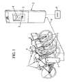
- each cycle 1 may be an electrically assisted cycle comprising a connector 9a (DOCK) on which can be connected a removable and rechargeable electric battery 9 (BATT.) which includes an external electrical connector 9b ( figure 3 ) complementary to said connector 9a.
- DOCK connector 9a
- BATT. removable and rechargeable electric battery 9
- BATT. battery 9b
- Such a battery is rechargeable by the user, usually at home, unlike batteries permanently mounted on the cycle, which recharge on the cycle while it is in storage position.
- the connector 9a is connected in particular to an electronic central unit of the cycle (CPU), for example a controller, microprocessor or the like.
- the battery 9 may optionally comprise a logic unit 9c (CTRL) such as a microcontroller or microprocessor, which may possibly have in memory a unique identifier readable by the central unit 10 via the connector 9a or otherwise, and the unit Central 10 also has a memory (or can access a memory) in which it can store this unique identifier.
- CTRL logic unit 9c
- the unique identifier of the battery if provided, could be stored in a specific identification circuit readable by the CPU 10, or other.
- the battery 9 supplies an electric motor 11 (M), for example a pedal assist electric motor which can be controlled by the central unit 10.
- M electric motor 11
- pedal assist electric motor which can be controlled by the central unit 10.
- the electric motor 11 is connected to one of the wheels of the cycle, for example the front wheel, and it can possibly be of the type that can operate either in motor mode to drive this wheel, or in generator mode to be driven by said wheel and generate an electric current supplying the battery 9.
- the central unit 10 can also be connected to an antitheft control device A, for example a simple button or a key device whose actuation during a temporary stopping of the cycle. , causes the motor 11 to be controlled by the central unit 10 to operate the motor 11 in generator mode in the absence of the battery 9, which makes it almost impossible to use the cycle and therefore is a deterrent against the theft of the cycle .
- an antitheft control device A for example a simple button or a key device whose actuation during a temporary stopping of the cycle.
- the central unit 10 can also also control at least one communication interface 12 (COM) which is adapted to communicate with a similar communication interface 13 (COM) belonging to each locking terminal 7.
- the communication interfaces 12, 13 can be of any known type and operate for example in wired mode, by induction, by radio waves or other.
- the interactive terminal 2 also includes an electronic central unit 19 (CPU) such as a microprocessor, microcontroller or the like, which communicates with the aforementioned devices 3-5 as well as with a communication interface 20 (COM). such as a MODEM communicating by radio or wireline with the aforementioned central server 8.
- CPU central unit
- COM communication interface
- each user preferably has his own removable battery 9, which he keeps with him especially to recharge it when he does not use it on a cycle 1.
- this recharging can be done by means of a dedicated electric charger 26 such as for example that represented on the Figures 3 and 4 , having a connector 27 complementary to the external connector 9b of the battery.
- the charger 26 may for example comprise an electronic central unit 31 (CTRL) adapted to communicate, via the connectors 9b, 27, with the logic unit 9c of a battery 9 connected to said charger.
- CTRL electronic central unit 31
- the electronic central unit 31 of the charger can also control the power supply circuit 28 of the charger, which can be connected to the electrical network via an external cable 29 and an electrical socket 30.
- the logic unit 9c of the battery can be adapted to control the switching device 22 of the battery according to battery control information exchanged between said central unit 31 of the charger and said logic unit 9c of the battery.
- the logic unit 9c of the battery 9 and the central unit 31 of the charger 26 may comprise identical or complementary codes to validate that the battery corresponds to the charger.
- the identifier of the battery 9 can be read by the electronic central unit 31 of the charger, which has in memory identification data corresponding to this identifier, and the central unit 31 of the charger is adapted to send to the logic unit 9c of the battery battery control information to switch the switching device 22 to the state connection, when the identifier read by the central unit 21 of the loader corresponds to said identification information.
- the logic unit 9c of the battery switches the switching device to the connection state, and the charger 26 supplies the battery 9 via the external connector of said battery. Conversely, if this correspondence is not validated, the logic unit 9c of the battery makes the switching device 22 pass or keep in the disconnected state, so that the switching device prevents recharging of the battery. This can prevent the charging of stolen batteries, if the thief could not steal a charger compatible with this battery.
- the device that has just been described operates as follows.
- a user When a user wishes to use a cycle 1 on the cycle storage station, he can identify for example on the interactive terminal 2 (by means of a card read by the card reader 5 of the interactive terminal or by typing a personal code on the keyboard 3 or by any other known means, after which the interactive terminal checks for example with the rental management server 8, that the user has the right to rent a cycle.
- each locking station 7 may comprise a card reader, for example a contactless card reader, on which subscriber users can read a contactless card to identify themselves, after which the locking station in The question communicates with the interactive terminal 2 which requests the authorization of the server as indicated above.
- a card reader for example a contactless card reader, on which subscriber users can read a contactless card to identify themselves, after which the locking station in The question communicates with the interactive terminal 2 which requests the authorization of the server as indicated above.
- a subscriber user can identify himself by means of his removable battery 9, which is personal to him as indicated above and whose identifier is memorized by the server with the other data of the subscriber, in a database of subscribers.
- the user when he arrives at the cycle storage station, to connect his personal battery 9 to the connector 9a of the desired cycle.
- the logic unit 9c of the battery then communicates its identifier to the central unit 10 of the cycle, which itself communicates with the central unit 19 of the interactive terminal 2 via the central unit 14 of the terminal 7 on which is locked the cycle.
- the interactive terminal 2 requests the server 8 to release the cycle 1.
- the server 8 checks whether the user is entitled to rent a cycle and if the battery 9 is not in a list of stolen batteries. If the situation is normal, the server gives the interactive terminal 2 the authorization to release cycle 1 and notes the rental start time. The interactive terminal 2 then controls the release of a cycle 1 of its locking terminal 7, so that the user can take it and use it.
- the server detects that the identifier of the battery 9 corresponds to a stolen battery when it receives a cycle release request subsequent to the connection of the battery 9 on the cycle, it sends to the interactive terminal 2 a battery blocking command, which is relayed by the interactive terminal and then by the central unit of the cycle to the logic unit 9c of the battery 9.
- the central unit 9c of the battery then switches the switching device to the disconnected state and permanently maintains it in this state, except to receive a release command from the server or from a service maintenance service. batteries. It is thus possible to neutralize the stolen batteries, which is an additional deterrent against theft. Note that this battery lock process can be used even if the battery identifier is not used to release the cycle: for example, in this case, the user can be asked to connect his battery 9 on cycle 1 before releasing the cycle, otherwise the cycle is not released.
- the logic unit 9c of the battery detects the connection of the battery either directly or indirectly by the causes the logical unit 9c to start talking with the central unit 10 of the cycle.
- the logic unit 9c controls the switching device 22 so as to switch it over. connection state. More generally, this switching mode switching control of the switching device 22 can be performed according to any control information received by the logic unit 9c (direct connection detection of the battery, dialogue with the central unit of the cycle , Or other).
- this transition in connection mode may be subordinated to the receipt of an order received from the central unit 10 of the cycle.
- the CPU of the cycle can first read the identifier of the battery, check that it is a valid identifier and then give the switch order in connection mode.
- the cycle 1 has been released by the lock terminal 7, the user can freely use it. When it has finished using it it makes the cycle on a cycle storage station (the one where it has borrowed the cycle or another) by engaging the cycle 1 on a free lock terminal 7 of this station.
- the interactive terminal 2 of this station then informs the server 8 that cycle 1 has been returned, and if server confirms that the situation is in order, has cycle 1 locked on the lock terminal 7. The user then resumes his battery 9.
- the logic unit 9c of the battery detects this disconnection as explained above and then commands the switching device 22 so as to switch it to the disconnected state.
- the battery can not be discharged untimely, even if its external connector 9 comes into contact with a conductive medium. This advantage is also valid if the external connector is protected in whole or in part by a shutter or plug or other when disconnected.
Landscapes
- Engineering & Computer Science (AREA)
- Mechanical Engineering (AREA)
- Transportation (AREA)
- Power Engineering (AREA)
- Chemical & Material Sciences (AREA)
- Combustion & Propulsion (AREA)
- Charge And Discharge Circuits For Batteries Or The Like (AREA)
- Lock And Its Accessories (AREA)
- Battery Mounting, Suspending (AREA)
Abstract
Description
La présente invention est relative aux systèmes automatiques de stockage de cycles et aux batteries pour de tels systèmes.The present invention relates to automatic cycle storage systems and batteries for such systems.
Plus particulièrement, l'invention concerne un système automatique de stockage de cycles comprenant :
- une pluralité de cycles électriques comportant chacun un moteur électrique et fonctionnant respectivement avec des batteries électriques rechargeables,
- une infrastructure fixe comportant une pluralité de postes de verrouillage sur lesquels peuvent se verrouiller lesdits cycles électriques et au moins un dispositif de commande externe adapté pour sélectivement autoriser le verrouillage et le déverrouillage des cycles électriques sur lesdits postes de verrouillage.
- a plurality of electric cycles each comprising an electric motor and operating respectively with rechargeable electric batteries,
- a fixed infrastructure comprising a plurality of locking stations on which said electrical cycles can be locked and at least one external control device adapted to selectively allow locking and unlocking of the electrical cycles on said locking stations.
Un système de stockage de cycles tel que décrit ci-dessus peut être utilisé par exemple pour mettre des cycles en libre service à disposition du public, moyennant identification de l'emprunteur du cycle et éventuellement paiement d'une location.A cycle storage system as described above can be used for example to make self-service cycles available to the public, by identifying the borrower of the cycle and possibly payment of a rental.
Le document
La présente invention a notamment pour but de pallier cet inconvénient.The present invention is intended to overcome this disadvantage.
A cet effet, selon l'invention, un système automatique de stockage de cycles du genre en question est caractérisé en ce que les batteries sont amovibles et indépendantes des cycles électriques, chaque batterie comportant un connecteur électrique externe,
en ce que chaque cycle électrique comporte un connecteur électrique de cycle accessible à un utilisateur pour connecter le connecteur électrique externe d'une desdites batteries sur le cycle et alimenter le cycle électrique,
et en ce que la batterie comporte un dispositif de commutation pouvant sélectivement basculer entre un état de connexion et un état de déconnexion adaptés pour respectivement permettre et interdire au connecteur électrique externe de ladite batterie de décharger de l'énergie électrique, et une unité logique commandant le dispositif de commutation de la batterie en fonction d'informations de commande de batterie reçues par ladite unité logique de la batterie.For this purpose, according to the invention, a system automatic storage cycle of the kind in question is characterized in that the batteries are removable and independent of the electrical cycles, each battery having an external electrical connector,
in that each electrical cycle comprises a cycle electrical connector accessible to a user for connecting the external electrical connector of one of said batteries to the cycle and supplying the electric cycle,
and in that the battery comprises a switching device that can selectively switch between a connection state and a disconnect state adapted to respectively allow and prevent the external electrical connector of said battery from discharging electrical energy, and a logic unit controlling the battery switching device according to battery control information received by said logic unit of the battery.
Grâce à ces dispositions, chaque utilisateur peut utiliser sa propre batterie ou en tout cas une batterie dont il maîtrise la charge, ce qui lui permet d'utiliser un cycle avec une batterie bien chargée. De plus, on évite également, de cette façon, que la batterie ne reste au froid en hiver, ce qui permet d'allonger considérablement la durée de vie de ladite batterie. De plus, la commande du dispositif de commutation en fonction d'informations reçues de l'infrastructure fixe, permet d'apporter des fonctionnalités supplémentaires, par exemple une protection supplémentaire contre le vol et/ou une protection de la batterie contre les déchargements intempestifs, ce qui est particulièrement utile dans le cas des batteries amovibles.Thanks to these provisions, each user can use his own battery or at least a battery which he controls the load, which allows him to use a cycle with a well-charged battery. In addition, it also avoids, in this way, that the battery does not stay cold in winter, which allows to significantly extend the life of said battery. Moreover, the control of the switching device according to information received from the fixed infrastructure makes it possible to provide additional functionalities, for example additional protection against theft and / or protection of the battery against untimely discharges, which is particularly useful in the case of removable batteries.
Dans différents modes de réalisation du système automatique de stockage de cycles selon l'invention, on peut éventuellement avoir recours en outre à l'une et/ou à l'autre des dispositions suivantes (utilisables éventuellement indépendamment les unes des autres et indépendamment des dispositions précitées) :
- la batterie comporte un accumulateur électrique et le dispositif de commutation de la batterie est adapté pour sélectivement relier ledit accumulateur au connecteur électrique externe de ladite batterie ;
- l'unité logique de la batterie est adaptée pour détecter si le connecteur électrique externe de la batterie est connecté au connecteur de cycle, et pour commander le dispositif de commutation de la batterie de façon à le faire basculer en état de déconnexion lorsque le connecteur électrique externe de batterie est déconnecté du connecteur de cycle ;
- l'unité logique de la batterie est adaptée pour commander le dispositif de commutation de la batterie de façon le faire basculer en état de connexion lorsque le connecteur électrique externe de la batterie est connecté au connecteur de cycle ;
- l'unité logique de la batterie communique avec une unité centrale électronique appartenant au cycle et les informations de commande de batterie comprennent des données de commande de batterie échangées entre l'unité logique de la batterie et l'unité centrale électronique du cycle ;
- l'unité logique de la batterie communique avec l'infrastructure fixe et est adaptée pour placer le dispositif de commutation en état de déconnexion lorsqu'elle reçoit des informations de blocage de batterie en provenance de ladite infrastructure fixe ;
- l'unité logique de la batterie communique avec l'unité centrale électronique du cycle, laquelle communique avec l'infrastructure fixe ;
- la batterie possède un identifiant et le système comporte des moyens pour transmettre cet identifiant à l'infrastructure fixe, ladite infrastructure fixe est adaptée pour communiquer avec l'unité logique de la batterie pour lui transmettre un ordre de blocage (notamment si l'identifiant de la batterie appartient à une batterie interdite d'utilisation, et ladite unité logique de la batterie est adaptée pour maintenir durablement le dispositif de commutation à l'état de déconnexion lorsqu'elle a reçu ledit ordre de blocage ;
- la batterie possède un identifiant et le système comporte des moyens pour transmettre cet identifiant à l'infrastructure fixe lorsque la batterie est connectée à un cycle électrique verrouillé sur un poste de verrouillage, et ladite infrastructure fixe est adaptée pour sélectivement déverrouiller ou non le cycle en fonction dudit identifiant ;
- l'identifiant de la batterie est lisible par une unité centrale électronique appartenant au cycle électrique, laquelle communique avec l'unité logique de la batterie et avec l'infrastructure fixe ;
- le système comporte également des chargeurs électriques adaptés pour charger les batteries, chaque chargeur comportant une unité centrale électronique adaptée pour communiquer avec l'unité logique d'une batterie connectée audit chargeur, l'unité logique de la batterie étant adaptée pour commander le dispositif de commutation en fonction d'informations de commande de batterie échangées entre ladite unité centrale du chargeur et ladite unité logique de la batterie, et le dispositif de commutation étant adapté pour empêcher aussi bien la recharge que la décharge de la batterie par le connecteur externe de ladite batterie lorsqu'il est à l'état déconnecté : on peut empêcher ainsi la recharge de batteries volées, si le voleur n'a pas pu voler un chargeur compatible avec cette batterie ;
- la batterie possède un identifiant lisible par l'unité centrale électronique du chargeur, lequel a en mémoire des données d'identification correspondant à cet identifiant, et l'unité centrale du chargeur est adaptée pour envoyer à l'unité logique de la batterie des informations de commande de batterie permettant de faire basculer le dispositif de commutation à l'état de connexion, lorsque l'identifiant lu par l'unité centrale du chargeur correspond auxdites informations d'identification.
- the battery comprises an electric accumulator and the battery switching device is adapted to selectively connect said accumulator to the external electrical connector of said battery;
- the logical unit of the battery is adapted to detect whether the external electrical connector of the battery is connected to the cycle connector, and to control the battery switching device so as to switch it to a disconnected state when the electrical connector external battery is disconnected from the cycle connector;
- the logic unit of the battery is adapted to control the battery switching device to switch to the connection state when the external battery electrical connector is connected to the cycle connector;
- the logic unit of the battery communicates with an electronic central unit belonging to the cycle and the battery control information comprises battery control data exchanged between the logical unit of the battery and the electronic central unit of the cycle;
- the logical unit of the battery communicates with the fixed infrastructure and is adapted to place the switching device in the disconnected state when it receives battery blocking information from said fixed infrastructure;
- the logical unit of the battery communicates with the electronic central unit of the cycle, which communicates with the fixed infrastructure;
- the battery has an identifier and the system comprises means for transmitting this identifier to the fixed infrastructure, said fixed infrastructure is adapted to communicate with the logical unit of the battery to transmit a blocking command (especially if the battery identifier belongs to a battery prohibited use, and said logic unit of the battery is adapted to sustainably maintain the switching device in the disconnected state when she received the said blocking order;
- the battery has an identifier and the system comprises means for transmitting this identifier to the fixed infrastructure when the battery is connected to a locked electrical cycle on a locking station, and said fixed infrastructure is adapted to selectively unlock the cycle in function of said identifier;
- the identifier of the battery is readable by an electronic central unit belonging to the electrical cycle, which communicates with the logic unit of the battery and with the fixed infrastructure;
- the system also comprises electric chargers adapted to charge the batteries, each charger comprising an electronic central unit adapted to communicate with the logic unit of a battery connected to said charger, the logic unit of the battery being adapted to control the device of switching according to battery control information exchanged between said charger central unit and said battery logic unit, and the switching device being adapted to prevent both charging and discharging of the battery by the external connector of said battery battery when it is in the disconnected state: one can thus prevent the recharge of stolen batteries, if the thief could not steal a charger compatible with this battery;
- the battery has an identifier readable by the electronic central unit of the charger, which stores in its memory identification data corresponding to this identifier, and the central unit of the charger is adapted to send to the logical unit of the battery battery control information for switching the switching device to the connection state, when the identifier read by the CPU of the loader corresponds to said identification information.
Par ailleurs, l'invention a également pour objet une batterie amovible utilisable dans un système tel que décrit ci-dessus, comportant :
- un connecteur électrique externe,
- un dispositif de commutation pouvant sélectivement basculer entre un état de connexion et un état de déconnexion adaptés pour respectivement permettre ou interdire au connecteur électrique externe de ladite batterie de décharger de l'énergie électrique,
- et une unité logique communiquant avec l'infrastructure fixe et commandant le dispositif de commutation de la batterie en fonction d'informations de commande de batterie reçues par ladite unité logique de la batterie.
- an external electrical connector,
- a switching device that can selectively switch between a connection state and a disconnect state adapted to respectively allow or prevent the external electrical connector of said battery from discharging electrical energy,
- and a logical unit communicating with the fixed infrastructure and controlling the battery switching device according to battery control information received by said logic unit of the battery.
D'autres caractéristiques et avantages de l'invention apparaîtront au cours de la description suivante d'une de ses formes de réalisation, donnée à titre d'exemple non limitatif, en regard des dessins joints.Other features and advantages of the invention will become apparent from the following description of one of its embodiments, given by way of non-limiting example, with reference to the accompanying drawings.
Sur les dessins :
- la
figure 1 est une vue schématique en perspective montrant un système automatique de stockage de cycles selon une forme de réalisation de l'invention, - la
figure 2 est un schéma bloc illustrant les composants électriques principaux du système de stockage de cycles de lafigure 1 , - la
figure 3 est une vue schématique en perspective d'une des batteries utilisables dans le système desfigures 1 et2 , avec son chargeur, - et la
figure 4 est une vue schématique en perspective illustrant la batterie connectée au chargeur.
- the
figure 1 is a schematic perspective view showing an automatic cycle storage system according to one embodiment of the invention, - the
figure 2 is a block diagram illustrating the main electrical components of the cycle storage system of thefigure 1 , - the
figure 3 is a schematic perspective view of one of the batteries usable in the system offigures 1 and2 , with its charger, - and the
figure 4 is a schematic perspective view illustrating the battery connected to the charger.
Sur les différentes figures, les mêmes références désignent des éléments identiques ou similaires.In the different figures, the same references designate identical or similar elements.
Comme représenté sur la
Ce système automatique de stockage de cycles peut comporter plusieurs stations de stockage de cycles, dont une est représentée sur la
La borne interactive 2 communique d'une part, avec le serveur central 8 qui gère les abonnements et les locations de cycles, et d'autre part, avec une pluralité de postes de verrouillage 7 qui permettent de verrouiller les cycles pendant leur stockage et qui peuvent par exemple se présenter sous la forme de bornes de verrouillage fixées au sol sur la voie publique et adaptées pour verrouiller chacune un cycle 1.The interactive terminal 2 communicates, on the one hand, with the central server 8 which manages the subscriptions and the rents of cycles, and on the other hand, with a plurality of locking stations 7 which make it possible to lock the cycles during their storage and which For example, they may be in the form of ground-mounted locking terminals on the public road and adapted to each lock a cycle 1.
Le cycle 1 comporte classiquement un châssis composé d'un cadre porté par la roue arrière et d'une fourche surmontée du guidon et montée sur la roue avant. Comme représenté sur la
Le connecteur 9a est relié notamment à une unité centrale électronique 10 du cycle (CPU), par exemple un contrôleur, microprocesseur ou similaire. La batterie 9 peut éventuellement comporter une unité logique 9c (CTRL) telle qu'un microcontrôleur ou microprocesseur, qui peut éventuellement avoir en mémoire un identifiant unique lisible par l'unité centrale 10 par le biais du connecteur 9a ou autrement, et l'unité centrale 10 possède également une mémoire (ou peut accéder à une mémoire) dans laquelle elle peut stocker cet identifiant unique. Eventuellement, l'identifiant unique de la batterie, s'il est prévu, pourrait être mémorisé dans un circuit d'identification spécifique lisible par l'unité centrale 10, ou autre.The
La batterie comporte en outre :
- un accumulateur électrique 21 relié au connecteur externe 9b par une liaison électrique,
- et un dispositif de commutation électronique 22 disposé sur cette liaison électrique et commandé par l'unité logique 9c en fonction d'informations de commande de batterie reçues par ladite unité logique de la batterie, pour sélectivement basculer entre un état de connexion et un état de déconnexion adaptés pour respectivement permettre et interdire au connecteur électrique externe 9b de ladite batterie de décharger de l'énergie électrique.
Avantageusement, le dispositif de commutation électronique coupe la liaison électrique entre l'accumulateur 21 et le connecteur externe 9b dans l'état de déconnexion, de sorte qu'il interdit alors non seulement la décharge de la batterie, mais également sa recharge.
- an
electric accumulator 21 connected to theexternal connector 9b by an electrical connection, - and an
electronic switching device 22 disposed on this electrical link and controlled by thelogic unit 9c as a function of battery control information received by said logic unit of the battery, for selectively switching between a connection state and a power state. disconnection adapted to respectively allow and prohibit the externalelectrical connector 9b of said battery to discharge electrical energy.
Advantageously, the electronic switching device cuts the electrical connection between theaccumulator 21 and theexternal connector 9b in the disconnected state, so that it then prohibits not only the discharge of the battery, but also its recharging.
L'unité logique 9c peut comporter par exemple :
une sortie 23 vers le dispositif decommutation 22,- au moins une entrée 24 reliée à l'accumulateur 21 pour recevoir par exemple une information de tension ou de charge de cet accumulateur, que ladite unité logique 9c peut mémoriser dans une mémoire interne ou externe (non représentée),
- au moins une entrée/
sortie 25 reliée au connecteur 9b et permettant à l'unité logique 9c de la batterie de dialoguer avec l'unité centrale 10 du cycle par l'intermédiaire des connecteurs 9a, 9b.
- an
output 23 to theswitching device 22, - at least one
input 24 connected to theaccumulator 21 to receive for example a voltage or charge information of this accumulator, that saidlogic unit 9c can store in an internal or external memory (not shown), - at least one input /
output 25 connected to theconnector 9b and allowing thelogic unit 9c of the battery to communicate with the central unit 10 of the cycle via theconnectors
La batterie 9 alimente un moteur électrique 11 (M), par exemple un moteur d'assistance électrique au pédalage qui peut être commandé par l'unité centrale 10.The
Le moteur électrique 11 est relié à une des roues du cycle, par exemple la roue avant, et il peut éventuellement être du type pouvant fonctionner soit en mode moteur pour entraîner cette roue, soit en mode générateur pour se faire entraîner par ladite roue et générer un courant électrique alimentant la batterie 9.The electric motor 11 is connected to one of the wheels of the cycle, for example the front wheel, and it can possibly be of the type that can operate either in motor mode to drive this wheel, or in generator mode to be driven by said wheel and generate an electric current supplying the
En temps normal, le fonctionnement du moteur 11 en mode moteur ou générateur est commandé par l'unité centrale 10, en fonction d'informations qu'elle reçoit de capteurs, notamment :
- un capteur de pédalage P adapté pour détecter ou mesurer la force de pédalage d'un utilisateur sur les pédales du cycle,
- éventuellement, un capteur de freinage adapté pour détecter un actionnement des freins du cycle par l'utilisateur,
- éventuellement un tachymètre (non représenté) mesurant la vitesse du cycle.
- a pedaling sensor P adapted to detect or measure the pedaling force of a user on the pedals of the cycle,
- optionally, a brake sensor adapted to detect an actuation of the brakes of the cycle by the user,
- optionally a tachometer (not shown) measuring the speed of the cycle.
De plus, dans l'exemple considéré ici, l'unité centrale 10 peut également être reliée à un dispositif de commande d'antivol A, par exemple un simple bouton ou un dispositif à clef dont l'actionnement, pendant un arrêt temporaire du cycle, fait commander le moteur 11 par l'unité centrale 10 pour faire fonctionner le moteur 11 en mode générateur en l'absence de la batterie 9, ce qui rend quasiment impossible l'utilisation du cycle et donc est une dissuasion contre le vol du cycle.In addition, in the example considered here, the central unit 10 can also be connected to an antitheft control device A, for example a simple button or a key device whose actuation during a temporary stopping of the cycle. , causes the motor 11 to be controlled by the central unit 10 to operate the motor 11 in generator mode in the absence of the
L'unité centrale 10 peut également commander également au moins une interface de communication 12 (COM) qui est adaptée pour communiquer avec une interface de communication similaire 13 (COM) appartenant à chaque borne de verrouillage 7. Les interfaces de communication 12, 13 peuvent être de tout type connu et fonctionner par exemple en mode filaire, par induction, par ondes radio ou autres.The central unit 10 can also also control at least one communication interface 12 (COM) which is adapted to communicate with a similar communication interface 13 (COM) belonging to each locking terminal 7. The communication interfaces 12, 13 can be of any known type and operate for example in wired mode, by induction, by radio waves or other.
L'interface de communication 13 de la borne de verrouillage 7, quant à elle, communique avec une unité centrale électronique 14 (CPU) propre à la borne de verrouillage 7 (microprocesseur, microcontrôleur ou autre), laquelle unité centrale 14 commande par ailleurs un verrou électrique 15 (LOCK - un exemple d'un tel verrou est donné par exemple dans le document
La borne interactive 2 comporte, quant à elle, également une unité centrale électronique 19 (CPU) telle qu'un microprocesseur, microcontrôleur ou autre, qui communique avec les périphériques 3-5 susmentionnés ainsi qu'avec une interface de communication 20 (COM) telle qu'un MODEM communiquant par radio ou par voie filaire avec le serveur central 8 susmentionné.The interactive terminal 2 also includes an electronic central unit 19 (CPU) such as a microprocessor, microcontroller or the like, which communicates with the aforementioned devices 3-5 as well as with a communication interface 20 (COM). such as a MODEM communicating by radio or wireline with the aforementioned central server 8.
Dans ce système, chaque utilisateur possède de préférence sa propre batterie amovible 9, qu'il conserve avec lui notamment pour la recharger lorsqu'il ne s'en sert pas sur un cycle 1. Avantageusement, cette recharge peut s'effectuer au moyen d'un chargeur électrique 26 dédié tel que par exemple celui représenté sur les
Le chargeur 26 peut par exemple comporter une unité centrale électronique 31 (CTRL) adaptée pour communiquer, par l'intermédiaire des connecteurs 9b, 27, avec l'unité logique 9c d'une batterie 9 connectée audit chargeur.The
L'unité centrale électronique 31 du chargeur peut également commander le circuit d'alimentation électrique 28 du chargeur, qui peut se raccorder au réseau électrique par l'intermédiaire d'un câble externe 29 et d'une prise électrique 30.The electronic
L'unité logique 9c de la batterie peut être adaptée pour commander le dispositif de commutation 22 de la batterie en fonction d'informations de commande de batterie échangées entre ladite unité centrale 31 du chargeur et ladite unité logique 9c de la batterie.The
Par exemple, l'unité logique 9c de la batterie 9 et l'unité centrale 31 du chargeur 26 peuvent comporter des codes identiques ou complémentaires permettant de valider que la batterie correspond au chargeur. Par exemple, l'identifiant de la batterie 9 peut être lu par l'unité centrale électronique 31 du chargeur, laquelle a en mémoire des données d'identification correspondant à cet identifiant, et l'unité centrale 31 du chargeur est adaptée pour envoyer à l'unité logique 9c de la batterie des informations de commande de batterie permettant de faire basculer le dispositif de commutation 22 à l'état de connexion, lorsque l'identifiant lu par l'unité centrale 21 du chargeur correspond auxdites informations d'identification.For example, the
Si cette correspondance est validée, l'unité logique 9c de la batterie fait passer le dispositif de commutation à l'état de connexion, et le chargeur 26 alimente la batterie 9 par le connecteur externe de ladite batterie. Inversement, si cette correspondance n'est pas validée, l'unité logique 9c de la batterie fait passer ou maintient le dispositif de commutation 22 à l'état de déconnexion, de sorte que le dispositif de commutation empêche la recharge de la batterie. On peut empêcher ainsi la recharge de batteries volées, si le voleur n'a pas pu voler un chargeur compatible avec cette batterie.If this correspondence is validated, the
Le dispositif qui vient d'être décrit fonctionne comme suit.The device that has just been described operates as follows.
Lorsqu'un utilisateur souhaite emprunter un cycle 1 sur la station de stockage de cycles, il peut s'identifier par exemple sur la borne interactive 2 (au moyen d'une carte lue par le lecteur de cartes 5 de la borne interactive ou en tapant un code personnel sur le clavier 3 ou par tout autre moyen connu, après quoi la borne interactive vérifie par exemple avec le serveur 8 de gestion de location, que l'utilisateur a le droit de louer un cycle.When a user wishes to use a cycle 1 on the cycle storage station, he can identify for example on the interactive terminal 2 (by means of a card read by the
En variante, chaque poste de verrouillage 7 peut comporter un lecteur de carte, par exemple un lecteur de carte sans contact, sur lequel les utilisateurs abonnés peuvent faire lire une carte sans contact pour s'identifier, après quoi le poste de verrouillage en question communique avec la borne interactive 2 qui demande l'autorisation du serveur comme indiqué ci-dessus.Alternatively, each locking station 7 may comprise a card reader, for example a contactless card reader, on which subscriber users can read a contactless card to identify themselves, after which the locking station in The question communicates with the interactive terminal 2 which requests the authorization of the server as indicated above.
Selon une autre variante particulièrement avantageuse, un utilisateur abonné peut s'identifier au moyen de sa batterie amovible 9, qui lui est personnelle comme indiqué ci-dessus et dont l'identifiant est mémorisé par le serveur avec les autres données de l'abonné, dans une base de données des abonnés. Dans ce cas, il suffit à l'utilisateur, lorsqu'il arrive à la station de stockage de cycles, de connecter sa batterie personnelle 9 sur le connecteur 9a du cycle souhaité. L'unité logique 9c de la batterie communique alors son identifiant à l'unité centrale 10 du cycle, qui elle-même communique avec l'unité centrale 19 de la borne interactive 2 par l'intermédiaire de l'unité centrale 14 de la borne de verrouillage 7 sur laquelle est verrouillé le cycle. Comme expliqué précédemment, la borne interactive 2 demande alors au serveur 8 l'autorisation de libérer le cycle 1.According to another particularly advantageous variant, a subscriber user can identify himself by means of his
Dans tous les cas évoqués ci-dessus, lorsqu'il reçoit une requête de libération d'un cycle, le serveur 8 vérifie si l'utilisateur est en droit de louer un cycle et si la batterie 9 n'est pas dans une liste de batteries volées. Si la situation est normale, le serveur donne à la borne interactive 2 l'autorisation de libérer le cycle 1 et note l'heure de début de location. La borne interactive 2 commande alors la libération d'un cycle 1 de sa borne de verrouillage 7, de façon que l'utilisateur puisse le prendre et l'utiliser.In all the cases mentioned above, when it receives a request to release a cycle, the server 8 checks whether the user is entitled to rent a cycle and if the
A l'inverse, si le serveur détecte que l'identifiant de la batterie 9 correspond à une batterie volée lorsqu'il reçoit une requête de libération de cycle subséquente à la connexion de la batterie 9 sur le cycle, il envoie à la borne interactive 2 un ordre de blocage de batterie, ordre qui est relayé par ladite borne interactive puis par l'unité centrale du cycle vers l'unité logique 9c de la batterie 9. L'unité centrale 9c de la batterie fait alors basculer le dispositif de commutation en état de déconnexion et le maintient définitivement ans cet état, sauf à recevoir un ordre de déblocage venant du serveur ou d'un service de maintenance des batteries. On peut ainsi neutraliser les batteries volées, ce qui est une dissuasion supplémentaire contre le vol. On notera que ce processus de blocage e batterie peut être utilisé même si l'identifiant de la batterie n'est pas utilisé pour libérer le cycle : par exemple, dans ce cas, il peut être demandé à l'utilisateur de connecter sa batterie 9 sur le cycle 1 avant de libérer le cycle, faute de quoi le cycle n'est pas libéré.Conversely, if the server detects that the identifier of the
Lorsque l'utilisateur connecte sa batterie 9 sur le connecteur 9a du cycle, son dispositif de commutation est initialement à l'état de déconnexion, et l'unité logique 9c de la batterie détecte la connexion de la batterie soit directement, soit indirectement par le fait que l'unité logique 9c commence à dialoguer avec l'unité centrale 10 du cycle. Lorsque l'unité logique 9c détecte cette connexion et sous réserve qu'elle n'ait pas reçu un ordre de blocage tel qu'expliqué ci-dessus, l'unité logique 9c commande le dispositif de commutation 22 de façon à le faire basculer en état de connexion. Plus généralement, cette commande de basculement en mode de connexion du dispositif de commutation 22 peut être effectuée en fonction de toute information de commande reçue par l'unité logique 9c (détection directe de connexion de la batterie, dialogue avec l'unité centrale du cycle, ou autre).When the user connects his
Eventuellement, ce passage en mode de connexion peut être subordonné à la réception d'un ordre reçu de l'unité centrale 10 du cycle. Par exemple, l'unité centrale du cycle peut d'abord lire l'identifiant de la batterie, vérifier que c'est un identifiant valide puis donner l'ordre de basculement en mode de connexion.Optionally, this transition in connection mode may be subordinated to the receipt of an order received from the central unit 10 of the cycle. For example, the CPU of the cycle can first read the identifier of the battery, check that it is a valid identifier and then give the switch order in connection mode.
Si le cycle 1 a été libéré par la borne de verrouillage 7, l'utilisateur peut librement l'utiliser. Lorsqu'il a terminé de l'utiliser il rend le cycle sur une station de stockage de cycle (celle où il a emprunté le cycle ou une autre) en engageant le cycle 1 sur une borne de verrouillage libre 7 de cette station. La borne interactive 2 de cette station informe alors le serveur 8 que le cycle 1 a été rendu, puis si serveur confirme que la situation est en ordre, fait verrouiller le cycle 1 sur la borne de verrouillage 7. L'utilisateur reprend alors sa batterie 9.If the cycle 1 has been released by the lock terminal 7, the user can freely use it. When it has finished using it it makes the cycle on a cycle storage station (the one where it has borrowed the cycle or another) by engaging the cycle 1 on a free lock terminal 7 of this station. The interactive terminal 2 of this station then informs the server 8 that cycle 1 has been returned, and if server confirms that the situation is in order, has cycle 1 locked on the lock terminal 7. The user then resumes his
Lorsque l'utilisateur déconnecte sa batterie 9 du connecteur 9a du cycle (en fin d'utilisation ou même lors d'un arrêt temporaire du cycle), l'unité logique 9c de la batterie détecte cette déconnexion comme expliqué ci-dessus et commande alors le dispositif de commutation 22 de façon à le faire basculer en état de déconnexion. La batterie ne peut alors pas se décharger intempestivement, même si son connecteur externe 9 vient en contact avec un milieu conducteur. Cet avantage vaut également si le connecteur externe est protégé en tout ou partie par un volet ou bouchon ou autre lorsqu'il est déconnecté.When the user disconnects his
Claims (13)
caractérisé en ce que les batteries (9) sont amovibles et indépendantes des cycles électriques, chaque batterie comportant un connecteur électrique externe (9b),
en ce que chaque cycle électrique (1) comporte un connecteur électrique de cycle (9a) accessible à un utilisateur pour connecter le connecteur électrique externe (9b) d'une desdites batteries (9) sur le cycle électrique et alimenter le cycle,
et en ce que la batterie comporte un dispositif de commutation (22) pouvant sélectivement basculer entre un état de connexion et un état de déconnexion adaptés pour respectivement permettre et interdire au connecteur électrique externe (9b) de ladite batterie de décharger de l'énergie électrique, et une unité logique (9c) commandant le dispositif de commutation (22) de la batterie en fonction d'informations de commande de batterie reçues par ladite unité logique de la batterie.
characterized in that the batteries (9) are removable and independent of the electric cycles, each battery having an external electrical connector (9b),
in that each electrical cycle (1) comprises a cycle electrical connector (9a) accessible to a user for connecting the external electrical connector (9b) of one of said batteries (9) to the electrical cycle and supplying the cycle,
and in that the battery comprises a switching device (22) that can selectively switch between a connection state and a disconnection state adapted to respectively allow and prevent the external electrical connector (9b) of said battery from discharging electrical energy. , and a logic unit (9c) controlling the battery switching device (22) based on battery control information received by said logic unit of the battery.
Applications Claiming Priority (1)
| Application Number | Priority Date | Filing Date | Title |
|---|---|---|---|
| FR1352536A FR3003535B1 (en) | 2013-03-21 | 2013-03-21 | AUTOMATIC CYCLE STORAGE SYSTEM AND BATTERY FOR SUCH A SYSTEM. |
Publications (1)
| Publication Number | Publication Date |
|---|---|
| EP2781446A1 true EP2781446A1 (en) | 2014-09-24 |
Family
ID=48741345
Family Applications (1)
| Application Number | Title | Priority Date | Filing Date |
|---|---|---|---|
| EP20140160678 Withdrawn EP2781446A1 (en) | 2013-03-21 | 2014-03-19 | Automatic cycle-storage system and battery for such a system |
Country Status (3)
| Country | Link |
|---|---|
| EP (1) | EP2781446A1 (en) |
| JP (1) | JP2014206045A (en) |
| FR (1) | FR3003535B1 (en) |
Cited By (4)
| Publication number | Priority date | Publication date | Assignee | Title |
|---|---|---|---|---|
| ITUB20159774A1 (en) * | 2015-12-30 | 2017-06-30 | Clear Channel Jolly Pubblicita S P A | SYSTEM TO SHARE PUBLIC ELECTRIC BICYCLES PROVIDED WITH AN AUTOMATIC ELECTRONIC SYSTEM TO MANAGE IN REMOTE THE ELECTRIC POWER OF THE SAME BICYCLES |
| CN107086331A (en) * | 2017-04-11 | 2017-08-22 | 李威 | A kind of electric vehicle management system, electric car, electronic vehicle main body and cell apparatus |
| EP3216687A1 (en) * | 2016-03-08 | 2017-09-13 | Intermobility SA | Electric bicycle and method for supplying power to the electric motor thereof |
| US11850969B1 (en) | 2022-08-23 | 2023-12-26 | Intercontinental Mobility Company | Portable motorized vehicles |
Citations (5)
| Publication number | Priority date | Publication date | Assignee | Title |
|---|---|---|---|---|
| JPH05316606A (en) * | 1992-05-13 | 1993-11-26 | Yamaha Motor Co Ltd | Charging system for motor-driven vehicle |
| JP2005196403A (en) * | 2004-01-06 | 2005-07-21 | Yamaha Motor Co Ltd | Lending system |
| EP1820722A1 (en) | 2006-02-21 | 2007-08-22 | Jcdecaux SA | Automatic cycle storage system |
| US20100228405A1 (en) * | 2007-06-13 | 2010-09-09 | Intrago Corporation | Shared vehicle management system |
| US20110148346A1 (en) * | 2009-12-22 | 2011-06-23 | Jcdecaux Sa | Automatic Cycle Storage System, Cycle For Such a System and Docking Structure For Such a Cycle |
Family Cites Families (3)
| Publication number | Priority date | Publication date | Assignee | Title |
|---|---|---|---|---|
| JP4113622B2 (en) * | 1998-09-09 | 2008-07-09 | 本田技研工業株式会社 | Electric vehicle |
| JP5741222B2 (en) * | 2011-05-31 | 2015-07-01 | ソニー株式会社 | Battery device, control method, and electric vehicle |
| FR2978414B1 (en) * | 2011-07-29 | 2016-04-01 | Jcdecaux Sa | AUTOMATIC CYCLE STORAGE SYSTEM AND CYCLE FOR SUCH A SYSTEM. |
-
2013
- 2013-03-21 FR FR1352536A patent/FR3003535B1/en active Active
-
2014
- 2014-03-19 EP EP20140160678 patent/EP2781446A1/en not_active Withdrawn
- 2014-03-20 JP JP2014057939A patent/JP2014206045A/en active Pending
Patent Citations (5)
| Publication number | Priority date | Publication date | Assignee | Title |
|---|---|---|---|---|
| JPH05316606A (en) * | 1992-05-13 | 1993-11-26 | Yamaha Motor Co Ltd | Charging system for motor-driven vehicle |
| JP2005196403A (en) * | 2004-01-06 | 2005-07-21 | Yamaha Motor Co Ltd | Lending system |
| EP1820722A1 (en) | 2006-02-21 | 2007-08-22 | Jcdecaux SA | Automatic cycle storage system |
| US20100228405A1 (en) * | 2007-06-13 | 2010-09-09 | Intrago Corporation | Shared vehicle management system |
| US20110148346A1 (en) * | 2009-12-22 | 2011-06-23 | Jcdecaux Sa | Automatic Cycle Storage System, Cycle For Such a System and Docking Structure For Such a Cycle |
Cited By (5)
| Publication number | Priority date | Publication date | Assignee | Title |
|---|---|---|---|---|
| ITUB20159774A1 (en) * | 2015-12-30 | 2017-06-30 | Clear Channel Jolly Pubblicita S P A | SYSTEM TO SHARE PUBLIC ELECTRIC BICYCLES PROVIDED WITH AN AUTOMATIC ELECTRONIC SYSTEM TO MANAGE IN REMOTE THE ELECTRIC POWER OF THE SAME BICYCLES |
| EP3188141A1 (en) * | 2015-12-30 | 2017-07-05 | Clear Channel Jolly Pubblicita' S.p.A. | Public electric bike sharing system provided with an automatic electronic system for remotely managing the electric supply for the bikes and relative operating method |
| EP3216687A1 (en) * | 2016-03-08 | 2017-09-13 | Intermobility SA | Electric bicycle and method for supplying power to the electric motor thereof |
| CN107086331A (en) * | 2017-04-11 | 2017-08-22 | 李威 | A kind of electric vehicle management system, electric car, electronic vehicle main body and cell apparatus |
| US11850969B1 (en) | 2022-08-23 | 2023-12-26 | Intercontinental Mobility Company | Portable motorized vehicles |
Also Published As
| Publication number | Publication date |
|---|---|
| JP2014206045A (en) | 2014-10-30 |
| FR3003535A1 (en) | 2014-09-26 |
| FR3003535B1 (en) | 2016-03-25 |
Similar Documents
| Publication | Publication Date | Title |
|---|---|---|
| EP2781397B1 (en) | Automatic cycle-storage system and battery for such a system | |
| EP2781440B1 (en) | Automatic cycle-storage system and battery for such a system | |
| US20100228405A1 (en) | Shared vehicle management system | |
| WO2006095092A1 (en) | System for automatically storing cycles and cycle therefor | |
| EP2781446A1 (en) | Automatic cycle-storage system and battery for such a system | |
| FR3014825A1 (en) | AUTOMATIC CYCLE STORAGE SYSTEM AND CYCLE FOR SUCH A SYSTEM. | |
| FR2978414A1 (en) | Automatic storage system for storing cycle, has control device communicated with central unit of host structure, and signaling device sending signal to user when battery of cycle is locked on fixed host structures without removing battery | |
| FR3003537A1 (en) | ELECTRIC ASSISTANCE CYCLE AND AUTOMATIC CYCLE STORAGE SYSTEM COMPRISING SUCH CYCLES. | |
| FR3022672A1 (en) | FLEET MANAGEMENT SYSTEM FOR VEHICLES, IN PARTICULAR ELECTRIC SCOOTERS | |
| WO2010037790A1 (en) | Method of charging with electrical energy a mobile entity implementing a remote mode of payment | |
| EP3216687B1 (en) | Electric bicycle and method for supplying power to the electric motor thereof | |
| EP2793197B1 (en) | Automatic system and method for access control | |
| WO2013001258A2 (en) | Charging terminal for an electrical vehicle, station and system using such a terminal | |
| FR2988068A1 (en) | AUTOMATIC CYCLE STORAGE SYSTEM, CYCLE FOR SUCH A SYSTEM AND USE OF A BATTERY FOR SUCH A CYCLE. | |
| WO2018172674A1 (en) | Automatic system for providing bicycles | |
| FR2978415A1 (en) | Automatic storage system for storing cycles, has signaling device sending warning signal to user when detecting units detect that battery and container are separated from each other by distance greater than predetermined distance | |
| FR2988506A1 (en) | Method for automatic provision of e.g. cycles, in public highway, involves providing alarm with telephone message that is emitted towards mobile communication terminals of users when control device has access to terminals | |
| FR3055302A1 (en) | AUTOMATIC VEHICLE STORAGE SYSTEM AND METHOD FOR SUPERVISION OF SUCH A SYSTEM | |
| WO2019158860A1 (en) | Method for recharging an electrical energy storage device storing electrical energy of a plurality of vehicles | |
| FR2925236A1 (en) | Self-service electric vehicle i.e. electric power-assisted bicycle, charging station, has connection control device for connecting electric supply source to socket after detection of data responding to certain criterion by user of vehicle | |
| FR3036540B1 (en) | BATTERY AND DEVICE AND METHOD FOR RECHARGING AND EXCHANGING SUCH BATTERY | |
| FR3076535A1 (en) | HUMAN PROPULSION VEHICLE WITH COMPACT STORAGE | |
| FR3053952A1 (en) | AUTOMATIC CYCLE STORAGE SYSTEM AND LATCHING STATION FOR SUCH A SYSTEM | |
| EP1460745A2 (en) | Charger for portable electronic devices and method thereof | |
| KR20100092294A (en) | Electric energy reusing system |
Legal Events
| Date | Code | Title | Description |
|---|---|---|---|
| PUAI | Public reference made under article 153(3) epc to a published international application that has entered the european phase |
Free format text: ORIGINAL CODE: 0009012 |
|
| 17P | Request for examination filed |
Effective date: 20140319 |
|
| AK | Designated contracting states |
Kind code of ref document: A1 Designated state(s): AL AT BE BG CH CY CZ DE DK EE ES FI FR GB GR HR HU IE IS IT LI LT LU LV MC MK MT NL NO PL PT RO RS SE SI SK SM TR |
|
| AX | Request for extension of the european patent |
Extension state: BA ME |
|
| R17P | Request for examination filed (corrected) |
Effective date: 20150310 |
|
| RBV | Designated contracting states (corrected) |
Designated state(s): AL AT BE BG CH CY CZ DE DK EE ES FI FR GB GR HR HU IE IS IT LI LT LU LV MC MK MT NL NO PL PT RO RS SE SI SK SM TR |
|
| 17Q | First examination report despatched |
Effective date: 20161006 |
|
| GRAP | Despatch of communication of intention to grant a patent |
Free format text: ORIGINAL CODE: EPIDOSNIGR1 |
|
| INTG | Intention to grant announced |
Effective date: 20181204 |
|
| STAA | Information on the status of an ep patent application or granted ep patent |
Free format text: STATUS: THE APPLICATION IS DEEMED TO BE WITHDRAWN |
|
| 18D | Application deemed to be withdrawn |
Effective date: 20190416 |