EP2781399A1 - Seat reclining apparatus for vehicle - Google Patents
Seat reclining apparatus for vehicle Download PDFInfo
- Publication number
- EP2781399A1 EP2781399A1 EP20140157759 EP14157759A EP2781399A1 EP 2781399 A1 EP2781399 A1 EP 2781399A1 EP 20140157759 EP20140157759 EP 20140157759 EP 14157759 A EP14157759 A EP 14157759A EP 2781399 A1 EP2781399 A1 EP 2781399A1
- Authority
- EP
- European Patent Office
- Prior art keywords
- seatback
- stopper
- turning
- inclining
- cam
- Prior art date
- Legal status (The legal status is an assumption and is not a legal conclusion. Google has not performed a legal analysis and makes no representation as to the accuracy of the status listed.)
- Granted
Links
- 230000007246 mechanism Effects 0.000 claims abstract description 118
- 230000001105 regulatory effect Effects 0.000 claims abstract description 49
- 238000003825 pressing Methods 0.000 claims description 44
- 210000000078 claw Anatomy 0.000 claims description 26
- 230000000903 blocking effect Effects 0.000 claims description 6
- 230000002093 peripheral effect Effects 0.000 description 46
- 239000000463 material Substances 0.000 description 11
- 230000004308 accommodation Effects 0.000 description 10
- 230000006870 function Effects 0.000 description 8
- 230000007935 neutral effect Effects 0.000 description 8
- 230000008859 change Effects 0.000 description 6
- 230000000694 effects Effects 0.000 description 6
- 239000002184 metal Substances 0.000 description 6
- 238000003466 welding Methods 0.000 description 5
- 229910000831 Steel Inorganic materials 0.000 description 4
- 230000001965 increasing effect Effects 0.000 description 4
- 230000006386 memory function Effects 0.000 description 4
- 239000010959 steel Substances 0.000 description 4
- 230000003247 decreasing effect Effects 0.000 description 3
- 230000035515 penetration Effects 0.000 description 3
- 230000000717 retained effect Effects 0.000 description 3
- 238000013459 approach Methods 0.000 description 2
- 230000005489 elastic deformation Effects 0.000 description 2
- 238000005242 forging Methods 0.000 description 2
- 230000007257 malfunction Effects 0.000 description 2
- 238000000034 method Methods 0.000 description 2
- 230000000149 penetrating effect Effects 0.000 description 2
- 230000008569 process Effects 0.000 description 2
- 230000004044 response Effects 0.000 description 2
- 230000002146 bilateral effect Effects 0.000 description 1
- 230000002708 enhancing effect Effects 0.000 description 1
- 230000001747 exhibiting effect Effects 0.000 description 1
- 230000001771 impaired effect Effects 0.000 description 1
- 230000001360 synchronised effect Effects 0.000 description 1
- 238000004804 winding Methods 0.000 description 1
Images








Classifications
-
- B—PERFORMING OPERATIONS; TRANSPORTING
- B60—VEHICLES IN GENERAL
- B60N—SEATS SPECIALLY ADAPTED FOR VEHICLES; VEHICLE PASSENGER ACCOMMODATION NOT OTHERWISE PROVIDED FOR
- B60N2/00—Seats specially adapted for vehicles; Arrangement or mounting of seats in vehicles
- B60N2/02—Seats specially adapted for vehicles; Arrangement or mounting of seats in vehicles the seat or part thereof being movable, e.g. adjustable
- B60N2/22—Seats specially adapted for vehicles; Arrangement or mounting of seats in vehicles the seat or part thereof being movable, e.g. adjustable the back-rest being adjustable
- B60N2/235—Seats specially adapted for vehicles; Arrangement or mounting of seats in vehicles the seat or part thereof being movable, e.g. adjustable the back-rest being adjustable by gear-pawl type mechanisms
- B60N2/2356—Seats specially adapted for vehicles; Arrangement or mounting of seats in vehicles the seat or part thereof being movable, e.g. adjustable the back-rest being adjustable by gear-pawl type mechanisms with internal pawls
-
- B—PERFORMING OPERATIONS; TRANSPORTING
- B60—VEHICLES IN GENERAL
- B60N—SEATS SPECIALLY ADAPTED FOR VEHICLES; VEHICLE PASSENGER ACCOMMODATION NOT OTHERWISE PROVIDED FOR
- B60N2/00—Seats specially adapted for vehicles; Arrangement or mounting of seats in vehicles
- B60N2/02—Seats specially adapted for vehicles; Arrangement or mounting of seats in vehicles the seat or part thereof being movable, e.g. adjustable
- B60N2/22—Seats specially adapted for vehicles; Arrangement or mounting of seats in vehicles the seat or part thereof being movable, e.g. adjustable the back-rest being adjustable
- B60N2/235—Seats specially adapted for vehicles; Arrangement or mounting of seats in vehicles the seat or part thereof being movable, e.g. adjustable the back-rest being adjustable by gear-pawl type mechanisms
- B60N2/2356—Seats specially adapted for vehicles; Arrangement or mounting of seats in vehicles the seat or part thereof being movable, e.g. adjustable the back-rest being adjustable by gear-pawl type mechanisms with internal pawls
- B60N2/2358—Seats specially adapted for vehicles; Arrangement or mounting of seats in vehicles the seat or part thereof being movable, e.g. adjustable the back-rest being adjustable by gear-pawl type mechanisms with internal pawls and provided with memory locks
-
- B—PERFORMING OPERATIONS; TRANSPORTING
- B60—VEHICLES IN GENERAL
- B60N—SEATS SPECIALLY ADAPTED FOR VEHICLES; VEHICLE PASSENGER ACCOMMODATION NOT OTHERWISE PROVIDED FOR
- B60N2/00—Seats specially adapted for vehicles; Arrangement or mounting of seats in vehicles
- B60N2/02—Seats specially adapted for vehicles; Arrangement or mounting of seats in vehicles the seat or part thereof being movable, e.g. adjustable
- B60N2/22—Seats specially adapted for vehicles; Arrangement or mounting of seats in vehicles the seat or part thereof being movable, e.g. adjustable the back-rest being adjustable
- B60N2/235—Seats specially adapted for vehicles; Arrangement or mounting of seats in vehicles the seat or part thereof being movable, e.g. adjustable the back-rest being adjustable by gear-pawl type mechanisms
- B60N2/2356—Seats specially adapted for vehicles; Arrangement or mounting of seats in vehicles the seat or part thereof being movable, e.g. adjustable the back-rest being adjustable by gear-pawl type mechanisms with internal pawls
- B60N2/236—Seats specially adapted for vehicles; Arrangement or mounting of seats in vehicles the seat or part thereof being movable, e.g. adjustable the back-rest being adjustable by gear-pawl type mechanisms with internal pawls linearly movable
Definitions
- This disclosure relates to a seat reclining apparatus for a vehicle.
- JP 2005-313833A discloses a seat reclining apparatus for a vehicle, for example.
- this seat reclining apparatus for a vehicle includes a disk-shaped locking mechanism 200, which selectively switches inclining of a seatback between a permitted state and a regulated state with respect to a seat cushion within a predetermined angle range (ready-for-seating region), together with a first operation member 201 that performs unlocking operation thereof.
- the seat reclining apparatus for a vehicle includes a pole 206, which engages with teeth 202a formed on an outer shape portion of a turning member 202 on a seatback side of the locking mechanism 200, in an upper portion of the locking mechanism 200 of the seatback.
- This pole 206 forms a second locking mechanism 205 that allows the seatback to incline forward to a predetermined forward tilt position exceeding the predetermined angle range (ready-for-seating region) through the unlocking operation of the second operation member (not illustrated).
- this seat reclining apparatus for a vehicle includes the second locking mechanism 205 that causes the seatback to incline forward to a predetermined forward tilt position, in addition to the ordinary locking mechanism 200.
- JP 2005-313833A (Reference 1)
- the second locking mechanism 205 in addition to the ordinary locking mechanism 200 that is disposed around an axis line of the seatback, the second locking mechanism 205 is necessarily disposed in the upper portion of the locking mechanism 200, thereby causing a complicated structure.
- both of the locking mechanisms 200 and 205 need to satisfy strength for holding the seatback, an increase in mass is unavoidable as well.
- the second operation member is operated in a circumstance where a person sitting on a seat leans on the seatback, there is a possibility that the seatback may immediately incline to a limited position (hereinafter, also referred to as "complete tilt position") or in the vicinity thereof within the ready-for-seating region in a rearward inclination direction.
- complete tilt position a limited position
- the second operation member is unlikely to be observed by a person sitting on the seat, if the seatback inclines to the complete tilt position or the like through an operation of the second operation member by a third person, there is a possibility that usability may be impaired.
- An aspect of this disclosure is directed to a seat reclining apparatus for a vehicle including a locking mechanism that is interposed between a seat cushion and a seatback and selectively switches inclining of the seatback between a permitted state and a regulated state with respect to the seat cushion; a first operation member that performs a first unlocking operation which allows the seatback to incline with respect to the seat cushion within a predetermined angle range with respect to the locking mechanism; a second operation member that performs a second unlocking operation which allows the seatback to incline with respect to the seat cushion to a predetermined forward tilt position exceeding the predetermined angle range with respect to the locking mechanism; and a stopper mechanism that regulates a rearward tilt of the seatback at a predetermined regulation angle position included within the predetermined angle range in a state of the second unlocking operation of the second operation member.
- the rearward tilt of the seatback is regulated at the predetermined regulation angle position by the stopper mechanism, and thus, it is possible to prevent the seatback from overly tilting rearward.
- the stopper mechanism includes a stopper link which is pivotally supported by a seat cushion side member; a stopper member which is provided in a seatback side member; a release link which is connected to each of the first operation member and the second operation member and turns to cause the locking mechanism to allow the inclining of the seatback with respect to the seat cushion to a predetermined forward tilt position in the state of the second unlocking operation of the second operation member; a first cam surface which is formed in the release link; a second cam surface which is formed in the stopper link, guides the stopper link so as to open a turning locus of the stopper member corresponding to a rearward inclining direction of the seatback when abutting on the first cam surface in a state where the inclining of the seatback is regulated with respect to the seat cushion by the locking mechanism, and allows the turning of the stopper link toward a side blocking the turning locus of the stopper member corresponding to the rearward inclining direction of the
- the stopper link in which the second cam surface is released from the first cam surface is urged by the elastic member, thereby turning so as to block the turning locus of the stopper member corresponding to the rearward inclining direction of the seatback. Therefore, it is possible to regulate the inclining of the seatback in the rearward inclining direction at an angle position (predetermined regulation angle position) where the stopper member abuts on the stopper link.
- the seat reclining apparatus further includes a cancellation member that stops blocking of the turning locus of the stopper member by the stopper link when the seatback is in a state of being farther inclined in the rearward inclining direction than the regulation angle position.
- a plurality of engagement holes are formed in the stopper member at intervals in a circumferential direction of a center axis of the seatback, and a claw portion which is engaged with any one of the plurality of engagement holes, regulates the inclining of the seatback in the rearward inclining direction, and allows the inclining of the seatback in a forward inclining direction when the stopper link in which the second cam surface is released from the first cam surface in the state of the second unlocking operation of the second operation member is urged to turn by the elastic member is formed in a tip portion of the stopper link.
- the regulation range is relatively elongated if there is one angle position to regulate the inclining of the seatback in the rearward inclining direction.
- a fluctuation of the regulation range can be prevented, and thus, it is possible to improve usability.
- the second cam surface abut on the first cam surface despite a state of the first unlocking operation of the first operation member.
- the release link is mounted on a hinge axis of the locking mechanism to be relatively turnable, and the seat reclining apparatus further includes a reception portion that is provided in the hinge axis; a protrusion piece that is provided in the release link and capable of pressing the reception portion toward the side in which the locking mechanism allows the inclining of the seatback in the state of the second unlocking operation of the second operation member; and a release link urging member that urges the release link in the turning direction corresponding to a side in which the locking mechanism regulates the inclining of the seatback.
- the protrusion piece of the release link presses the reception portion, and thus, it is possible to allow the inclining of the seatback by the locking mechanism.
- the hinge axis turns to a side in which the locking mechanism allows the inclining of the seatback.
- the release link is urgingly held by the release link urging member, and thus, it is possible to prevent following turning thereof. For this reason, it is possible to further lessen a possibility of a malfunction of the stopper mechanism, for example.
- the aspect of this disclosure provides an effect to prevent the seatback in a state inclinable to the forward tilt position in accordance with the operation of the operation member from overly tilting rearward.
- a seat reclining apparatus for a vehicle including a walk-in mechanism will be described.
- a front-back direction, a width direction and an up-down direction are considered to match each of the directions in a vehicle.
- reference characters "L" and "R” may be respectively applied to the reference numerals of the members disposed at left and right facing the front of the vehicle.
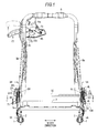
- a pair of lower rails 1 arranged in parallel in the width direction in an aspect of extending in the front-back direction (direction orthogonal to paper surface in Fig. 1 ) are fixed on a floor of a vehicle (not illustrated), and a pair of upper rails 2 are respectively supported by both of these lower rails 1 to be movable in the front-back direction.
- the lower rail 1 and the upper rail 2 configure a seat slide mechanism. In the configuration thereof, a movement of the upper rail 2 in the front-back direction with respect to the lower rail 1 is selectively allowed by a slide locking mechanism (not illustrated).
- An approximately square frame-shaped cushion frame 3 forming a frame of a seat cushion is placed on both of the upper rails 2.
- a pair of lower plates 4L and 4R formed of plate materials are respectively and fixedly attached to an outer side surface of a rear end portion of a pair of cushion side frames 3a configuring both of the side portions thereof in the width direction by welding.
- an approximately square frame-shaped seatback frame 6 forming a frame of a seatback is turnably (inclinably) connected to both of the lower plates 4L and 4R through a pair of locking mechanisms 5L and 5R.
- lower end portions of a pair of backside frames 6a configuring both of the side portions of the seatback frame 6 in the width direction are adjacently disposed on each of inner sides of the rear end portion (lower plates 4L, 4R) of both of the cushion side frames 3a in the width direction.
- a pair of rod-shaped hinge axes 91 L and 91 R having an axis line extended in the width direction respectively penetrate the lower end portions of both of the back side frames 6a together with both of the lower plates 4L and 4R.
- Both of the hinge axes 91 L and 91 R respectively and turnably support members (second member 20L, 20R) on the back side frame 6a of both of the locking mechanism 5L and 5R.
- both of the hinge axes 91 L and 91 R are fixedly attached to a tubular connection shaft 92 coaxially extended therewith in the width direction so as to integrally turn.
- both of the hinge axes 91 L and 91 R connectedly move through the connection shaft 92, thereby turning.
- the seatback frame 6 is connected to be turnable about the axis line of the connection shaft 92 and the like through both of the locking mechanisms 5L and 5R with respect to both of the lower plates 4L and 4R. Accordingly, an angle position (inclined angle) of the seatback is adjustable with respect to the seat cushion.
- fixing flanges 7L and 7R extended outward in the width direction on an upper side of the hinge axes 91 L and 91 R protrude.
- approximately L-shaped movable flanges 8L and 8R extended outward in the width direction on an upper side of the lower plates 4L and 4R and the fixing flanges 7L and 7R are bonded.
- an inner end portion and an outer end portion of a coil spring (not illustrated) are respectively locked. This coil spring urges to turn the seatback in a forward tilt direction with respect to the seat cushion.
- the seatback (seatback frame 6) is configured to be able to incline with respect to the seat cushion (seat cushion frame 3) about the axis line of the hinge axes 91 L and 91 R within a range from a "forward tilt position" which greatly inclines forward to a "complete tilt position” which greatly inclines rearward.
- the angle position of the seatback (seatback frame 6) when the movable flanges 8L and 8R abut on the front side stopper 4a corresponds to the forward tilt position
- the angle position of the seatback (seatback frame 6) when the movable flanges 8L and 8R abut on the rear side stopper 4b corresponds to the complete tilt position.
- the movable flanges 8L and 8R and the front side stopper 4a configure a front side stopper mechanism.
- the inclining range of the seatback with respect to the seat cushion is largely divided into a "forward tilting region" on the forward tilt position side and an “adjustment region” on the complete tilt position side. Then, the seatback is in an erected state in an "upright position” which is an angle position on a border between the forward tilting region and the adjustment region.
- the locking mechanisms 5L and 5R adjust and maintain the angle position of the seatback with respect to the seat cushion mainly within this adjustment region.
- the adjustment region is further divided into a "ready-for-seating region" on the upright position side and a "not-ready-for-seating region” on the complete tilt position side. Then, an angle position on a border between the ready-for-seating region and the not-ready-for-seating region is referred to as a "fixed point restoration position".
- the ready-for-seating region is an inclining range of the seatback suitable for a general seating posture, and for example, when the seatback is inclined from an arbitrary angle position of the ready-for-seating region to the forward tilt position, the seatback is erected to cancel the forward tilt thereafter, and thus, it is possible to be restored to the original angle position immediately before the forward tilt (full memory range).
- the not-ready-for-seating region is an inclining range of the seatback suitable for a special seating posture (for example, nap-taking posture), and for example, when the seatback is inclined from an arbitrary angle position of the not-ready-for-seating region to the forward tilt position, the seatback is erected to cancel the forward tilt thereafter, and thus, it is possible to be positioned in the fixed point restoration position (fixed point restoration range).
- a special seating posture for example, nap-taking posture
- a predetermined angle position of the seatback (seatback frame 6) indicated by a solid line is an angle position in which the seatback is mostly set when a general person to be seated takes a seat (hereinafter, referred to as "neutral position").
- the forward tilt position in the forward tilting region is an angle position of the seatback to enhance convenience of getting on and off a rear seat.
- the above-described slide locking apparatus is released and the like in accordance with the inclining of the seatback to the forward tilt position, and the seat cushion is configured to slide forward with respect to the floor of a vehicle (so-called walk-in function).
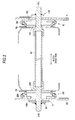
- the locking mechanism 5L includes disk-shaped first and second members 10L and 20L.
- the first member 10L is fixedly attached to an inner side surface (seat cushion side) of the lower plate 4L by welding being concentric with the hinge axis 91 L (connection shaft 92), and the second member 20L is fixedly attached to an outer side surface (seatback side) of a lower end portion of the back side frame 6a by welding being concentric with the hinge axis 91 L (connection shaft 92) in the same manner.
- These first member 10L and second member 20L are retained not to fall out in an axis line direction by a ring-shaped holder 29L formed of a metal plate.
- the first member 10L is molded by half blanking of the metal plate, for example, and has a circular concave portion 11 open toward the second member 20L side.
- the concave portion 11 has an inner peripheral surface 11a about the axis line of the hinge axis 91 L (first member 10L and the second member 20L).
- each of approximately fan-shaped convex portions 12 is disposed on a circumference at intervals of an equivalent angle.
- Each of the convex portions 12 forms guide walls 13 and 14 on both sides thereof in the circumferential direction.
- the guide walls 13 and 14 respectively on the adjacent convex portions 12 facing each other in the circumferential direction are extended in parallel with each other in the radial direction about the axis line, and associated with a bottom surface of the concave portion 11 to form approximately U-shaped groove-like guide grooves 15 extended in the radial direction about the axis line on the circumference at intervals of an equivalent angle.
- These guide grooves 15 communicate with each other in a central portion exhibiting an approximately Y shape in its entirety.
- an approximately circular penetration hole 16 is formed in the central portion where three of the guide grooves 15 of the first member 10L communicate with each other.
- a locking hole 16a is formed in this penetration hole 16 outwardly in a predetermined angle position in the radial direction.
- the second member 20L is molded by half blanking of the metal plate, for example, and has an outer peripheral surface 20a of which an outer diameter is equivalent to an inner diameter of the inner peripheral surface 11a of the first member 10L while having a circular concave portion 21 open toward the first member 10L side.
- Inner teeth 22 are formed across the overall periphery of an inner peripheral surface 21 a about the axis line of the hinge axis 91 L (first member 10L and second member 20L) of the concave portion 21.
- an approximately circular accommodation concave portion 23 is formed to be concentric with the concave portion 21.
- an approximately arc-shaped engagement protrusion portion 24L protruding toward the center at a predetermined angle position is formed on an inner peripheral surface 23a of the accommodation concave portion 23, an approximately arc-shaped engagement protrusion portion 24L protruding toward the center at a predetermined angle position is formed.
- the second member 20L fits into the outer peripheral surface 20a thereof so as to be in slide contact with the inner peripheral surface 11a of the first member 10L.
- outer peripheral portions of the first member 10L and the second member 20L are in a state of being fit by the inner peripheral surface 11a of the first member 10L and the outer peripheral surface 20a of the second member 20L, and the holder 29L is mounted thereon.
- the first member 10L and the second member 20L are retained not fall out in the axis line direction in a state where the relative turning is allowed by this holder 29L.
- first poles 31 L, 32L and 33L are installed between the first member 10L and the second member 20L.
- the first poles 31 L to 33L are mounted on a position between adjacent two guide walls 13 and 14 to be disposed at intervals of an equivalent angle in the circumferential direction about the axis line.
- the first poles 31 L to 33L are made by forging and the like of a steel material and include a first block 41 and a second block 42 which are formed in different levels from each other in the axis line direction.
- the first block 41 in the radial direction, the first block 41 is disposed on the inner peripheral surface 21 a side of the second member 20L, and the second block 42 is disposed on an axial center of the second member 20L. Both width end portions of these first block 41 and the second block 42 match each other and formed to be parallel to each other in straight lines.
- Outer teeth 43 enabled to mesh with the inner teeth 22 of the second member 20L are formed in an arc-shaped outer end (end surface facing inner teeth 22 of second member 20L) of the first block 41.
- a first pole side groove cam portion 44L penetrating in a plate thickness direction is opened in an approximately central portion in the width direction.
- both width end portions of the first poles 31 L to 33L are guided to move in the radial direction about the axis line in an aspect of slide contact with both of the guide walls 13 and 14.
- the first poles 31 L to 33L move back and forth in the radial direction along the both of the guide walls 13 and 14, thereby meshing or releasing (disengaging) the outer teeth 43 with respect to the inner teeth 22.
- inner surface cam portions 45L engaging with an outer peripheral portion of the cam 34L are formed in an inner end (rear surface which is end surface facing opposite to outer end) of the first block 41.
- the inner surface cam portions 45L formed in step difference portions of the first poles 31 L and 33L include three of pole side cam surfaces 45aL, 45bL and 45cL on the central portion of the first poles 31 L and 33L and on both sides thereof in the circumferential direction. These pole side cam surfaces 45aL, 45bL and 45cL face the outer peripheral portion (cam surface 51 L) of the cam 34L.
- the pole side cam surfaces 45aL, 45bL and 45cL are configured to include cam surfaces with an oblique surface which approaches the outer peripheral portion of the cam 34L when locking is in operation in accordance with turning in a counterclockwise turning direction (hereinafter, also referred to as "locking turning direction") as shown in the drawing, of the cam 34L.
- an arc-shaped first pole side engagement protrusion portion 46L protrudes on an outer side of the second block 42 in the radial direction so as to face the accommodation concave portion 23 (inner peripheral surface 23a) in the radial direction.
- the first pole side engagement protrusion portion 46L is disposed on the central portion of the first poles 31 L and 33L in the circumferential direction.
- an inner surface cam portion 47L engaging with the outer peripheral portion of the cam 34L is formed in the inner end (rear surface which is end surface opposite to outer end) of the first block 41.
- the inner surface cam portion 47L formed in the step difference portion of the first pole 32L includes pole side cam surfaces 47aL and 47bL identical to the pole side cam surfaces 45aL and 45bL, and a pole side cam surface 47cL replacing the pole side cam surface 45cL.
- the pole side cam surface 47cL faces the outer peripheral portion (cam surface 51 L) of the cam 34L and is molded to form a wedge-shaped space between itself and the guide wall 13 facing in the circumferential direction. In other words, the guide wall 13 and the pole side cam surface 47cL are molded to have an interval which becomes outwardly narrower in the radial direction.
- an arc-shaped first pole side engagement protrusion portion 48L protrudes on an outer side of the second block 42 in the radial direction so as to face the accommodation concave portion 23 (inner peripheral surface 23a).
- This first pole side engagement protrusion portion 48L is disposed in the portion on a preceding side in a clockwise turning direction of the first pole 32L in the circumferential direction as shown in the drawing.
- the cam 34L is disposed on the inner peripheral sides of the first poles 31 L to 33L which become an inside of the concave portion 21 of the second member 20L to be turnable about the axis line of the second member 20L and the like.
- the cam 34L is made of the plate-shaped steel plate by pressing and the like and basically has a flat plate shape without a step difference. Then, an approximately oval-shaped cam fitting hole 34a penetrated in the plate thickness direction along the axis line is formed in the central portion of the cam 34L.
- the cam 34L is integrally turnable with the hinge axis 91 L and the like on the inner peripheral side of the first poles 31L to 33L (first block 41) by fitting and inserting a tip portion of the hinge axis 91L to the cam fitting hole 34a.
- the cam 34L has three sets of cam surface 51 L on the circumference of the outer peripheral portion thereof at intervals of an equivalent angle.
- Each of the cam surfaces 51 L includes three pressing cam portions 51 aL, 51 bL and 51 cL respectively in the central portion of the circumferential direction and on both sides in the circumferential direction.
- the two pressing cam portions 51 aL and 51 bL among these are enabled to abut on the two pole side cam surfaces 45aL and 45bL facing the first poles 31 L and 33L or the two pole side cam surfaces 47aL and 47bL facing the first pole 32L.
- These two pressing cam portions 51aL and 51bL press the corresponding pole side cam surfaces 45aL, 45bL, 47aL and 47bL when the cam 34L turns in the locking turning direction.
- the one remaining pressing cam portion 51cL among these is enabled to abut on the remaining pole side cam surface 45cL facing the first poles 31 L and 33L, and presses the corresponding pole side cam surface 45cL when the cam 34L turns in the locking turning direction.
- the pressing cam portion 51cL accommodates a sphere-shaped pressing member 36L in the above-described wedge-shaped space formed between the pole side cam surface 47cL and the guide wall 13 of the first pole 32L.
- the pressing member 36L comes into slide contact with the pole side cam surface 47cL and the guide wall 13 and is movable in the radial direction.
- the pressing cam portion 51cL can circumscribe the pressing member 36L and presses the pressing member 36L when the cam 34L turns in the locking turning direction.
- the pressing cam portions 51aL to 51cL are respectively held in an angle position to abut on (be in pressed contact with) the pole side cam surfaces 45aL to 45cL of the first poles 31 L and 33L, and the pole side cam surfaces 47aL and 47bL and the pressing member 36L of the first pole 32L.
- the pressing member 36L comes into pressed contact with each of the guide wall 13 and the pole side cam surface 47cL when pressed by the cam 34L.
- a pressing force of the pressing member 36L is decomposed into a component force of a movement direction component (radial direction component) of the first pole 32L and the component force of a width direction component (circumferential direction component) of the pole which is a direction orthogonal to the movement direction.
- the pressing cam portions 51 aL and 51 bL are separated away from the pole side cam surfaces 45aL and 45bL of the first poles 31 L and 33L or the pole side cam surfaces 47aL and 47bL of the first pole 32L.
- the pressing cam portion 51cL is separated away from the pole side cam surface 45cL of the first poles 31 L and 33L, or separated away from the pressing member 36L.
- a plurality (three) of engagement protrusions 52L are provided to protrude on a side surface of the cam 34L at intervals on the circumference. These engagement protrusions 52L are inserted into the first pole side groove cam portion 44L of the first poles 31 L to 33L to be engaged therewith. The first pole side groove cam portion 44L and the engagement protrusions 52L are operated to move the first poles 31L to 33L inward in the radial direction by the turning of the cam 34L in the unlocking turning direction.
- the first pole side groove cam portion 44L is molded to gradually move outward in the radial direction as it becomes closer to the cam 34L in the unlocking turning direction (clockwise turning direction as shown in the drawing). Accordingly, in accordance with the turning of the cam 34L in the unlocking turning direction, the first poles 31 L to 33L of which the first pole side groove cam portion 44L is pressed by the engagement protrusion 52L are drawn inward in the radial direction.
- the coil spring 35 urges to turn the cam 34L in the locking turning direction so as to cause the first poles 31 L to 33L to engage with the second member 20L in the radial direction and is accommodated inside the penetration hole 16 of the first member 10L.
- the coil spring 35 is formed, for example, by winding an approximately flat rectangular wire rod in a predetermined coil shape and mounted on a position between the first member 10L and the cam 34L. In other words, an outer end portion 35a of the coil spring 35 is locked by the locking hole 16a, and an inner end portion 35b is locked by a locking portion (not illustrated) provided to protrude on an end surface of the cam 34L.
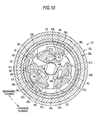
- the cam 34L is urged to turn in the locking turning direction (counterclockwise turning direction in Fig. 5A ) with respect to the first member 10L due to the urging force by the coil spring 35, presses the first poles 31 L to 33L outward in the radial direction through the cam surface 51 L, and causes each of outer teeth 43 to respectively mesh with the inner teeth 22 of the second member 20L.
- the memory ring 60 has a ring shape disconnected at one place and is enabled to contract in diameter by elastically deforming inward in the radial direction while enabled to increase in diameter by elastically deforming outward in the radial direction.
- the memory ring 60 causes its disconnection portion S to be positioned between the first pole side engagement protrusion portions 46L and 48L of the adjacent first poles 31 L and 32L.
- the memory ring 60 is accommodated to be able to slide that is, to be turnable in the circumferential direction with respect to the accommodation concave portion 23 of the second member 20L.
- the memory ring 60 a portion near the first pole 31 L side interposing the disconnection portion S therebetween is relatively contracted in diameter, and arc-shaped outer peripheral surface and inner peripheral surface of the portion form a turning allowance portion 61 and a first unlocking engagement surface 62.
- the memory ring 60 has an arc-shaped fixed point restoration protrusion portion 63 protruding inward in the radial direction from the central portion in the first unlocking engagement surface 62 in the circumferential direction.
- the memory ring 60 forms an engaged portion 64 by causing the end portion near the first pole 32L (first pole side engagement protrusion portion 48L) side to protrude inward in the radial direction interposing the disconnection portion S.
- This engaged portion 64 is set to overlap with the first pole side engagement protrusion portion 48L at a position in the radial direction at all times regardless of a position of the first pole 32L moving along the guide groove 15 in the radial direction.
- An arc-shaped inner peripheral surface interposed between the first unlocking engagement surface 62 and the engaged portion 64 of the memory ring 60 forms a first locking engagement surface 65 with a larger inner diameter than the inner diameter of the first unlocking engagement surface 62.
- a border position (step difference) between the first unlocking engagement surface 62 and the first locking engagement surface 65 is set to overlap with the first pole side engagement protrusion portion 46L, which is positioned on the first locking engagement surface 65, in a position in the radial direction at all times, for example, when the first pole 31 L moves outward in the radial direction along the guide groove 15, that is, when the outer teeth 43 of the first pole 31 L mesh with the inner teeth 22.
- the turning in the counterclockwise turning direction as shown in the drawing with respect to the first pole 31 L that is, the turning in the counterclockwise turning direction as shown in the drawing with respect to the first member 10L is set to be regulated at all times.
- the step difference-shaped border position between the first unlocking engagement surface 62 and the first locking engagement surface 65 forms a regulation surface 66.
- the regulation surface 66 is set to partially overlap with the first pole side engagement protrusion portion 46L which is positioned on the first locking engagement surface 65 in a position in the radial direction at all times.
- the turning in the counterclockwise turning direction as shown in the drawing with respect to the first pole 31 L that is, the turning in the counterclockwise turning direction as shown in the drawing with respect to the first member 10L is set to be regulated at all times by being half-engaged in the radial direction with respect to the first pole side engagement protrusion portion 46L in the regulation surface 66.
- the unlocking operation of the cam 34L in this case is also referred to as a first unlocking operation.
- the turning of the memory ring 60 with respect to the first member 10L is regulated at all times.
- an engagement protrusion portion 24L provided in the second member 20L is disposed in the turning allowance portion 61 in the circumferential direction. Therefore, when the turning of the memory ring 60 with respect to the first member 10L is regulated, the engagement protrusion portion 24L (second member 20L) is allowed to turn within a range of the turning allowance portion 61.
- Fig. 5A and Fig. 6 illustrate a state where the seatback is in the neutral position.
- the second member 20L which turns in the counterclockwise direction as shown in the drawing with respect to the memory ring 60 (and the first member 10L) in a state where the outer teeth 43 and the inner teeth 22 are out of mesh from each other is regulated in its turning by the engagement protrusion portion 24L reaching an end edge of the turning allowance portion 61.
- the turning of the second member 20L with respect to the first member 10L in this case causes the seatback to incline forward with respect to the seat cushion, and hereinafter, it is also referred to as "forward turning". Therefore, the state where the engagement protrusion portion 24L reaches the end edge of the turning allowance portion 61 in the forward turning of the second member 20L denotes that the seatback is in the upright position.
- the second member 20L which turns in the clockwise direction as shown in the drawing with respect to the memory ring 60 (and the first member 10L) in the state where the outer teeth 43 and the inner teeth 22 are out of mesh from each other is regulated in its turning by the engagement protrusion portion 24L reaching an end edge of the turning allowance portion 61.
- the turning of the second member 20L with respect to the first member 10L in this case causes the seatback to incline rearward with respect to the seat cushion, and hereinafter, it is also referred to as "rearward turning". Therefore, the state where the engagement protrusion portion 24L reaches the end edge of the turning allowance portion 61 in the rearward turning of the second member 20L denotes that the seatback is in the complete tilt position.
- the regulation surface 66 is set not to overlap with the first pole side engagement protrusion portion 46L in a position in the radial direction. Therefore, in this case, the memory ring 60 is disengaged from the first pole side engagement protrusion portion 46L in the radial direction on the regulation surface 66, and thus, the turning in the counterclockwise turning direction as shown in the drawing with respect to the first pole 31 L, that is, the turning in the counterclockwise turning direction as shown in the drawing with respect to the first member 10L is set to be allowed. At the same time, the memory ring 60 becomes integrally turnable with the second member 20L by frictionally engaging with the second member 20L due to the elastic deformation of itself.
- the memory ring 60 starts to integrally turn while maintaining the relative positions with the second member 20L. Then, accordingly, the first pole side engagement protrusion portion 46L which is positioned on the regulation surface 66 is mounted on the first unlocking engagement surface 62 from the first locking engagement surface 65.
- the first pole 31 L in a state of being out of mesh from the inner teeth 22 is regulated in moving outward in the radial direction by the first unlocking engagement surface 62 on which the first pole side engagement protrusion portion 46L is mounted, thereby maintaining the out of mesh state.
- the same can be applied to the other first poles 32L and 33L which connectedly move through the cam 34L.
- the unlocking operation of the cam 34L in this case is also referred to as a second unlocking operation.
- the second member 20L turns rearward together with the memory ring 60, and thus, the first pole 31 L is enabled to engage with the inner teeth 22 at the moment the first locking engagement surface 65 reaches the first pole side engagement protrusion portion 46L.
- the same can be applied to the other first poles 32L and 33L which connectedly move through the cam 34L. Then, the first poles 31L to 33L mesh with the inner teeth 22, thereby regulating the rearward turning of the second member 20L as well as the memory ring 60 not to turn therebeyond.
- the turning position of the second member 20L with respect to the first member 10L in this case matches the turning position when the second member 20L starts to turn together with the memory ring 60 in accordance with the second unlocking operation of the cam 34L.
- the angle position in which the rearward inclining of the seatback is regulated matches the original angle position (hereinafter, also referred to as "memory position") in which the seatback starts to incline forward in accordance with the second unlocking operation of the cam 34L.
- the memory ring 60 engages with the first pole side engagement protrusion portion 46L in the radial direction in the fixed point restoration protrusion portion 63, thereby regulating the turning in the counterclockwise turning direction as shown in the drawing with respect to the first pole 31L, that is, the turning in the counterclockwise turning direction as shown in the drawing with respect to the first member 10L again. That is, the turning of the memory ring 60 with respect to the first member 10L is regulated at all times, thereby enabling the turning with respect to the second member 20L. In other words, even if the seatback is in the stage of reaching the forward tilt position, the memory ring 60 still maintains the abutment state between the fixed point restoration protrusion portion 63 and the first pole side engagement protrusion portion 46L.
- the second member 20L turns rearward together with the memory ring 60, and thus, the first pole 31 L is enabled to mesh with the inner teeth 22 at the moment the first locking engagement surface 65 reaches the first pole side engagement protrusion portion 46L.
- the same can be applied to the other first poles 32L and 33L which connectedly move through the cam 34L. Then, the first poles 31L to 33L mesh with the inner teeth 22, thereby regulating the rearward turning of the second member 20L as well as the memory ring 60 not to turn therebeyond.
- the turning amount of the second member 20L with respect to the first member 10L in this case matches a predetermined angle corresponding to an angle between the regulation surface 66 and the fixed point restoration protrusion portion 63. That is, the angle position in which the rearward inclining of the seatback is regulated matches the angle position which is inclined rearward from the forward tilt position by a predetermined angle.
- the above-described fixed point restoration position of the seatback corresponds to the angle position to be restored at this time.
- the seatback is set to the fixed point restoration position when raised up to cancel the forward tilt. In this manner, when the forward inclining is started from the not-ready-for-seating region for a special seating posture, the seatback is stored in the ready-for-seating region in accordance with canceling the forward tilt, thereby enhancing operability.
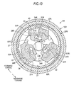
- the locking mechanism 5R includes disk-shaped first and second members 10R and 20R.
- the first member 10R is fixedly attached to an inner side surface (seat cushion side) of the lower plate 4R by welding being concentric with the hinge axis 91 R (connection shaft 92), and the second member 20R is fixedly attached to an outer side surface (seatback side) of a lower end portion of the back side frame 6a by welding being concentric with the hinge axis 91 R (connection shaft 92) in the same manner.
- These first member 10R and second member 20R are retained not to fall out in an axis line direction by a ring-shaped holder 29R formed of a metal plate.
- the first member 10R is molded by the half blanking of the metal plate, for example, and has approximately the same structure as the first member 10L except for being bilaterally symmetric.
- the second member 20R is molded by the half blanking of the metal plate, for example, and has approximately the same structure as the second member 20L except being bilaterally symmetric.
- the second member 20R forms a second unlocking engagement surface 26 on an inner peripheral surface of the engagement protrusion portion 24R and forms a second locking engagement surface 27 on the inner peripheral surface 23a between the adjacent engagement protrusion portion 24R.
- second poles 31 R, 32R and 33R are installed between the first member 10R and the second member 20R.
- the second poles 31 R to 33R are made by forging and the like of the steel material and have approximately the same structures as that of each of the first poles 31 L to 33L except being bilaterally symmetric.
- a second pole side groove cam portion 44R penetrated in the plate thickness direction is opened in an approximately central portion in the width direction.
- an arc-shaped second pole side engagement protrusion portion 46R protrudes on an outer side of the second block 42 in the radial direction so as to face the accommodation concave portion 23 (inner peripheral surface 23a).
- the second pole side engagement protrusion portion 46R is disposed in the central portion of the second poles 31 R to 33R in the circumferential direction.
- inner surface cam portions 45R engaging with an outer peripheral portion of the cam 34R are formed in an inner end (rear surface which is an end surface facing opposite to outer end) of the first block 41.
- the inner surface cam portions 45R formed in step difference portions of the second poles 31 R and 33R include three of pole side cam surfaces 45aR, 45bR and 45cR on the central portion of the second poles 31 R and 33R and on both sides thereof in the circumferential direction. These pole side cam surfaces 45aR, 45bR and 45cR face the outer peripheral portion (cam surface 51 R) of the cam 34R.
- the pole side cam surfaces 45aR, 45bR and 45cR are configured to include cam surfaces with the oblique surface which approaches the outer peripheral portion of the cam 34R when locking is in operation in accordance with turning in a counterclockwise turning direction (hereinafter, also referred to as "locking turning direction") as shown in the drawing, of the cam 34R.
- an inner surface cam portion 47R engaging with the outer peripheral portion of the cam 34R is formed in the inner end (rear surface which is an end surface facing opposite to outer end) of the first block 41.
- the inner surface cam portion 47R formed in the step difference portion of the second pole 32R includes pole side cam surfaces 47aR and 47bR identical to the pole side cam surfaces 45aR and 45bR, and a pole side cam surface 47cR replacing the pole side cam surface 45cR.
- the pole side cam surface 47cR faces the outer peripheral portion (cam surface 51 R) of the cam 34R and is molded to form the wedge-shaped space between itself and the guide wall 13 facing in the circumferential direction. In other words, the guide wall 13 and the pole side cam surface 47cR are molded to have an interval which becomes outwardly narrower in the radial direction.
- the cam 34R is made of the plate-shaped steel plate by pressing and the like and has approximately the same structure as that of the cam 34L except for being bilaterally symmetric.
- the cam 34R is integrally turnable with the hinge axis 91 R and the like on the inner peripheral side of the second poles 31 R to 33R by fitting and inserting a tip portion of the hinge axis 91 R to the cam fitting hole 34a.
- the cams 34L and 34R (locking mechanisms 5L, 5R) on the left and right are connected to each other through the hinge axes 91 L and 91 R and the connection shaft 92 so as to synchronized in operation.
- the cam 34R has three sets of cam surface 51 R on the circumference of the outer peripheral portion thereof at intervals of an equivalent angle.
- Each of the cam surfaces 51 R includes three pressing cam portions 51aR, 51bR and 51cR respectively in the central portion of the circumferential direction and on both sides in the circumferential direction.
- the two pressing cam portions 51 aR and 51 bR among these are enabled to abut on the two pole side cam surfaces 45aR and 45bR facing the second poles 31 R and 33R or the two pole side cam surfaces 47aR and 47bR facing the second pole 32R.
- These two pressing cam portions 51aR and 51bR press the corresponding pole side cam surfaces 45aR, 45bR, 47aR and 47bR when the cam 34R turns in the locking turning direction.
- the one remaining pressing cam portion 51cR among these is enabled to abut on the remaining pole side cam surface 45cR facing the second poles 31 R and 33R, and presses the corresponding pole side cam surface 45cR when the cam 34R turns in the locking turning direction.
- the pressing cam portion 51cR accommodates a sphere-shaped pressing member 36R in the above-described wedge-shaped space formed between the pole side cam surface 47cR of the second pole 32R and the guide wall 13.
- the pressing member 36R comes into slide contact with the pole side cam surface 47cR and the guide wall 13 and is movable in the radial direction.
- the pressing cam portion 51cR can circumscribe the pressing member 36R and presses the pressing member 36R when the cam 34R turns in the locking turning direction.
- the pressing cam portions 51aR to 51cR are respectively held in an angle position to abut on (be in pressed contact with) the pole side cam surfaces 45aR to 45cR of the second poles 31 R and 33R, and the pole side cam surfaces 47aR and 47bR and the pressing member 36R of the second pole 32R.
- the pressing member 36R comes into pressed contact with each of the guide wall 13 and the pole side cam surface 47cR when pressed by the cam 34R.
- a pressing force of the pressing member 36R is decomposed into the component force of the movement direction component (radial direction component) of the second pole 32R and the component force of the width direction component (circumferential direction component) of the pole which is the direction orthogonal to the movement direction.
- a force in the circumferential direction in which the width end portion of the second pole 32R and the guide wall 13 are separated away from each other is generated due to the wedge effect by the pressing component force of the width direction component of this second pole 32R, thereby filling a gap between the width end portion of the second pole 32R and the guide wall 14. Accordingly, rattling of the seatback with respect to the seat cushion is prevented.
- the pressing cam portions 51 aR and 51 bR are separated away from the pole side cam surfaces 45aR and 45bR of the second poles 31 R and 33R or the pole side cam surfaces 47aR and 47bR of the second pole 32R.
- the pressing cam portion 51cR is separated away from the pole side cam surface 45cR of the second poles 31 R and 33R, or separated away from the pressing member 36R.
- a plurality (three) of engagement protrusions 52R protrude on a side surface of the cam 34R at intervals on the circumference. These engagement protrusions 52R are inserted into the second pole side groove cam portion 44R of the second poles 31 R to 33R to be engaged therewith. The second pole side groove cam portion 44R and the engagement protrusions 52R are operated to move the second poles 31 R to 33R inward in the radial direction by the turning of the cam 34R in the unlocking turning direction.
- the second pole side groove cam portion 44R is molded to gradually move outward in the radial direction as being closer to the cam 34R in the unlocking turning direction (clockwise turning direction as shown in the drawing). Accordingly, in accordance with the turning of the cam 34R in the unlocking turning direction, the second poles 31R to 33R of which the second pole side groove cam portion 44R is pressed by the engagement protrusion 52R are drawn inward in the radial direction.
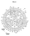
- the cam 34R is urged to turn in the locking turning direction (counterclockwise turning direction in Fig. 12 ) with respect to the first member 10R due to the urging force by the coil spring 35, presses the second poles 31 R to 33R outward in the radial direction by the cam surface 51 R, and causes each of the outer teeth 43 to respectively mesh with the inner teeth 22 of the second member 20R.
- the second pole side engagement protrusion portion 46R is positioned between the adjacent engagement protrusion portions 24R, that is, on the second locking engagement surface 27.
- the second pole side engagement protrusion portion 46R is allowed to relatively turn within a range of the second locking engagement surface 27 with respect to the second member 20R.
- the unlocking operation of the cam 34R in this case is also referred to as the first unlocking operation.
- the second member 20R which turns in the clockwise direction as shown in the drawing with respect to the first member 10R in the state where the outer teeth 43 and the inner teeth 22 are out of mesh from each other is regulated in its turning by the engagement protrusion portion 24R reaching the second pole side engagement protrusion portion 46R.
- the turning of the second member 20R with respect to the first member 10R in this case is the forward turning.
- the second member 20R which turns in the counterclockwise direction as shown in the drawing with respect to the first member 10R in the state where the outer teeth 43 and the inner teeth 22 are out of mesh from each other is regulated in its turning by the engagement protrusion portion 24R reaching the second pole side engagement protrusion portion 46R.
- the turning of the second member 20R with respect to the first member 10R in this case is the rearward turning.
- the engagement protrusion portion 24R is set not to overlap with the second pole side engagement protrusion portion 46R, which is positioned on the second locking engagement surface 27, in a position in the radial direction.
- the second member 20R is disengaged from the second pole side engagement protrusion portion 46R in the radial direction in the engagement protrusion portion 24R, and thus, for example, the turning further in the clockwise turning direction as shown in the drawing with respect to the second poles 31 R to 33R, that is, the turning further in the clockwise turning direction as shown in the drawing with respect to the first member 10R is set to be allowed.
- the second member 20R starts the forward turning with respect to the first member 10R in this state, the second pole side engagement protrusion portion 46R which is positioned on the second locking engagement surface 27 is mounted on the second unlocking engagement surface 26 from the second locking engagement surface 27, accordingly.
- the second poles 31 R to 33R in a state of being out of mesh from the inner teeth 22 are regulated in moving outward in the radial direction by the second unlocking engagement surface 26 on which the second pole side engagement protrusion portion 46R is mounted, thereby maintaining the out of mesh state. Therefore, the forward turning of the second member 20R in this case is allowed until reaching the turning position corresponding to the forward tilt position of the seatback.
- the unlocking operation of the cam 34R in this case is also referred to as the second unlocking operation.
- the second member 20R turns rearward, and thus, the second poles 31 R to 33R are enabled to mesh with the inner teeth 22 at the moment the second locking engagement surface 27 reaches the second pole side engagement protrusion portion 46R.
- the first poles 31 L to 33L which connectedly move on the opposite side through the connection shaft 92 and the like, need to be meshed with the inner teeth 22.
- the operation when the second poles 31 R to 33R mesh with the inner teeth 22 is restricted by the operation of the first poles 31 L to 33L on the opposite side related to the restoration in the memory position and the like.
- the tip portion of the hinge axis 91 R protruding from the lower plate 4R on one side in the axis line direction is linked to a first operation member 71 made of the plate material, for example, and configured to turn on a side in which the cam 34R connected to the hinge axis 91 R is in the first unlocking operation when the tip portion of the first operation member 71 is operated to be lifted up (hereinafter, also referred to as "first unlocking operation").
- first unlocking operation a side in which the cam 34R connected to the hinge axis 91 R is in the first unlocking operation when the tip portion of the first operation member 71 is operated to be lifted up.
- first unlocking operation the cam 34L on the opposite side also turns to the first unlocking operation side through the connection shaft 92 and the hinge axis 91 L.
- an attachment member 6b which spreads out on the corner portion thereof is provided.
- an arm-like second operation member 72 made of the plate material is turnably supported in the vertical direction by an axis 73.
- the second operation member 72 is urged to turn downward by a restoration spring (not illustrated) at all times.
- stoppers 74a and 74b are provided on an upper side and a lower side of the second operation member 72, and the operational range of the second operation member 72 is defined by these stoppers 74a and 74b.
- the tip portion of the hinge axis 91 L protruding from the lower plate 4L on one side in the axis line direction is linked to a release link 100 made of the plate material, for example.
- the tip portion of the release link 100 is connected to an intermediate portion of the second operation member 72 in the longitudinal direction through a cable 75 which is a double tube-type cable with flexibility to be guided inside an outer cylinder T, for example.
- the cam 34L connected to the hinge axis 91 L is configured to turn to the second unlocking operation side.
- the cam 34R on the opposite side also turns to the second unlocking operation side through the connection shaft 92 and the hinge axis 91 R.
- a terminal of the outer cylinder T of the cable 75 is held by a cable holder 6c which is formed in the attachment member 6b while the other terminal is held by a cable holder 104 fixedly attached to the lower plate 4L.
- a cable holder 6c which is formed in the attachment member 6b while the other terminal is held by a cable holder 104 fixedly attached to the lower plate 4L.
- Fig. 1 an intermediate portion of the cable 75 and the outer cylinder T is not illustrated.
- turning angle ⁇ 1 indicates the turning angle ⁇ corresponding to the maximum operating amount when the first operation member 71 is in the first unlocking operation.
- Turning angle ⁇ 2 (> ⁇ 1) indicates the turning angle ⁇ corresponding to the maximum operating amount when the second operation member 72 is in the second unlocking operation. Therefore, the turning angle ⁇ 2 matches the tuning angle ⁇ of the cam 34L corresponding to the operating amount in which the second operation member 72 abuts on the stopper 74a.
- sliding amount S1 indicates changes of the sliding amount SL of the first pole 31 L when the cams 34L and 34R are in the second unlocking operation
- sliding amount S2 indicates the changes of the sliding amount SL of the second pole 31 R when the cams 34L and 34R are in the second unlocking operation.
- Turning angle ⁇ 3 indicates the turning angle ⁇ when the engagement protrusions 52L and 52R abut on the first pole side engagement protrusion portion 46L and the second pole side engagement protrusion portion 46R via an idling section during the unlocking operation of the cams 34L and 34R.
- turning angle ⁇ 4 indicates the turning angle ⁇ corresponding to sliding amount Sr when the outer teeth 43 of the first pole 31 L and the second pole 31 R, and the inner teeth 22 of the second members 20L and 20R are released in tooth tips from each other.
- sliding amount S3 indicates changes of the sliding amount SL of the outer teeth 43 of the first pole 31 L and the second pole 31 R, and the inner teeth 22 of the second members 20L and 20R when these teeth mesh with each other due to the urging force of the coil spring 35.
- the sliding amounts SL are set to identically change with each other.
- the changes of the sliding amount SL in this case are adjusted and set by the cam surfaces 51 L and 51 R of the cams 34L and 34R, and the shapes of the inner cam portions 45L and 45R of the first pole 31 L and the second pole 31 R.
- the sliding amounts S1 and S2 are set to identically change with each other for the sliding amount SL in the beginning when the cams 34L and 34R start the second unlocking operation, and the outer teeth 43 of the first pole 31 L and the second pole 31 R, and the inner teeth 22 of the second members 20L and 20R finish to release the tooth tips from each other.
- the sliding amounts S1 and S2 are set to change differently from each other for the sliding amount SL.
- sliding amount St1 when first pole side engagement protrusion portion 46L of the first pole 31 L is mounted on the first unlocking engagement surface 62 of the memory ring 60 is set to be greater than the sliding amount St2 when the second pole side engagement protrusion portion 46R of the second pole 31 R is mounted on the second unlocking engagement surface 26 of the second member 20R.
- the seatback is prevented from being unable to tilt forward exceeding the predetermined angle range.
- an increasing amount of the sliding amount S1 of the first pole 31 L is set to be greater than the increasing amount of the sliding amount S2 of the second pole 31 R with respect to the increasing amount of the turning angle ⁇ .
- a moving speed at which the first pole 31 L is separated away from the inner teeth 22 in the radial direction is set to be faster than the moving speed at which the second pole 31 R is separated away from the inner teeth 22 in the radial direction.
- the changes of the sliding amount SL when the first pole side engagement protrusion portion 46L of the first pole 31 L is mounted on the first unlocking engagement surface 62 of the memory ring 60, and the changes of the sliding amount SL when the second pole side engagement protrusion portion 46R of the second pole 31 R is mounted on the second unlocking engagement surface 26 of the second member 20R are adjusted and set by the shapes of the first pole side groove cam portion 44L and the second pole side groove cam portion 44R with which the engagement protrusions 52L and 52R of the cams 34L and 34R are engaged.
- the changes of the sliding amount SL when the first pole side engagement protrusion portion 46L of the first pole 31 L is mounted on the first unlocking engagement surface 62 of the memory ring 60 are adjusted and set by the shapes of the first pole side groove cam portion 44L and the second pole side groove cam portion 44R with which the engagement protrusions 52L and 52R of the cams 34L and 34R are engaged.
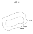
- an inner wall surface 44aL of the first pole side groove cam portion 44L related to the drawing-back of the first pole 31 L in the vicinity where the second pole side engagement protrusion portion 46R of the second pole 31 R is mounted on the second unlocking engagement surface 26 of the second member 20R is raised more outwardly in the radial direction than an inner wall surface 44aR of the second pole side groove cam portion 44R related to the drawing-back of the second pole 31 R in the same manner, as indicated in a dotted-chain line in Fig. 16 . Accordingly, a relative increase in the moving speed for the first pole 31L to be separated away from the inner teeth 22 in the radial direction is realized.
- the first operation member 71 is molded in an approximately bow shape and turnably supported by the tip portion of the hinge axis 91 R.
- the first operation member 71 has a movable stopper 71 a protruding to an upper front side substantially along the radial direction about the hinge axis 91 R from a base end portion thereof.
- This movable stopper 71 a is disposed on a side to proceed in the clockwise turning direction as shown in the drawing about the hinge axis 91 R with respect to the fixed flange 7R and disposed to cause the turning locus thereof to be blocked by the fixed flange 7R.
- the first operation member 71 is urged and held (pulled) in a predetermined initial turning position by a restoration spring 76 extended between the lower plate 4R and itself.
- the maximum turning range when performing a lift up operation (first unlocking operation) with respect to the tip portion of the first operation member 71 is regulated within a range where the movable stopper 71 a abuts on the fixed flange 7R.
- the turning angle ⁇ corresponding to the operating amount of the first operation member 71 in this case matches the turning angle ⁇ 1.
- the tip of the hinge axis 91 R is adjacent to the outside of the first operation member 71 which is a lower side of the fixed flange 7R, and is fit into and fixedly attached to a link member 80 made of the plate material.
- a link member 80 made of the plate material.
- an arc-shaped long hole 81 is formed about the hinge axis 91 R.
- a pin 77 inserted through the long hole 81 to be slidable is fixed.
- the first operation member 71 is turnably supported with respect to the tip portion of the hinge axis 91 R, and urged and held in a predetermined initial turning position by the restoration spring 76.
- the cam 34R which is integrated with the hinge axis 91 R is urged to turn in the turning direction (clockwise turning direction in Fig. 17 ) on a side where locking operation is applied by the coil spring 35 at all times, the link member 80 is normally disposed in a position where an end portion (front end portion) of the long hole 81 is locked by the pin 77 of the first operation member 71 in the initial turning position.
- the link member 80 integrally turns with the first operation member 71 in the counterclockwise turning direction as shown in the drawing as the end portion (front end portion) of the long hole 81 is pressed by the pin 77. Then, in accordance with the turning of the link member 80, the hinge axis 91 R integrally turns therewith in the same direction.
- the cam 34R which is integrated with the hinge axis 91 R performs the first unlocking operation against the urging force of the coil spring 35.
- the release link 100 is molded in an approximately L-shape, and the tip portion of the hinge axis 91 L is fit into and fixedly attached thereto.
- the cam 34L which is integrated with the hinge axis 91 L is urged to turn in the turning direction (counterclockwise turning direction in Fig. 20 ) on the side where locking operation is applied by the coil spring 35 at all times, the release link 100 is normally held in a predetermined initial turning position together therewith.
- an arc-shaped long hole 101 is formed about the hinge axis 91 L.
- a terminal 75a of the cable 75 extending from the second operation member 72 is inserted through the long hole 101 to be slidable. Then, in a state where the release link 100 is held in the initial turning position, the terminal 75a of the cable 75 is positioned in an end portion (lower end portion) of the long hole 101. In the lower end portion of the lower plate 4L, a cable holder 104 which holds a terminal of the outer cylinder T is fixedly attached.
- the release link 100 turns in the clockwise turning direction as shown in the drawing as the one end portion (lower end portion) of the long hole 101 is pressed by the terminal 75a. Then, in accordance with the turning of the release link 100, the hinge axis 91L integrally turns therewith in the same direction. In this case, the cam 34R which is integrated with the hinge axis 91 L performs the second unlocking operation against the urging force of the coil spring 35.
- the release link 100 turns in the clockwise turning direction as shown in the drawing, since the movement of the terminal 75a is allowed inside the long hole 101, the turning of the release link 100 is not transmitted to the cable 75 or the second operation member 72.
- the link member 80 integrally turns therewith. In this case, since the movement of the pin 77 is allowed inside the long hole 81 as described above, the turning of the link member 80 is not transmitted to the first operation member 71.
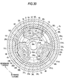
- an approximately bow-shaped switching piece 102 extending upward in the circumferential direction about the hinge axis 91 L is formed.
- An outer peripheral surface of a base end portion of the switching piece 102 forms a operation regulation surface 102a as the circular first cam surface about the hinge axis 91 L.
- an outer peripheral surface of the tip portion of the switching piece 102 forms an approximately linear operation allowance surface 102b facing further inner peripheral side along to the tip than the circle along which the operation regulation surface 102a is formed.
- This switching piece 102 configures a stopper mechanism 110 which regulates the rearward tilt of the seatback in the fixed point restoration position (predetermined regulation angle position) in a case where the second operation member 72 is in the second unlocking operation when the seatback is in the ready-for-seating region.
- the stopper mechanism 110 is configured to include the movable flange 8L, the switching piece 102, a stopper link 112 which is turnably connected to a rear upper portion (that is, in the vicinity of rear side stopper 4b) of the lower plate 4L by a pin 111 to be an upper portion of the switching piece 102, and a stopper link urging member 113.
- the stopper link 112 is made of the plate material, for example, and has an approximately bow-shaped stopper piece 112a extending toward the movable flange 8L substantially along the circumferential direction about the hinge axis 91 L while having an approximately gulf-shaped engagement surface 112b as the second cam surface extending downward toward the releasing link 100 (switching piece 102).
- the engagement surface 112b abuts on the outer peripheral surface of the switching piece 102 when the stopper link 112 turns in the clockwise turning direction around the pin 111 as shown in the drawing, and thus, the stopper link 112 is basically regulated not to turn therebeyond.
- the stopper link urging member 113 is formed of a torsion coil spring, for example, and of which a terminal is locked by the pin 111 fixedly attached to the lower plate 4L while the other terminal is locked by the stopper piece 112a, thereby urging the stopper link 112 to a side turning in the clockwise turning direction around the pin 111 as shown in the drawing.
- the stopper link 112 urged to turn by the stopper link urging member 113 is set to abut on the operation regulation surface 102a of the switching piece 102 in the engagement surface 112b. Therefore, the stopper link 112 causes the stopper piece 112a to be close to the hinge axis 91 L side when the engagement surface 112b is relatively pressed outward in the radial direction about the hinge axis 91 L by the operation regulation surface 102a. Then, the outer peripheral surface of the stopper piece 112a is disposed on a further inner peripheral side than the movable flange 8L substantially along the circumferential direction about the hinge axis 91L.
- the movable flange 8L proceeds further in front of the seat than a front end of the stopper piece 112a and opens upper portion of the stopper piece 112a.
- the operation allowance surface 102b of the switching piece 102 reaches the engagement surface 112b of the stopper link 112, that is, the operation regulation surface 102a of the switching piece 102 releases the engagement surface 112b of the stopper link 112, and thus, the stopper piece 112a of the stopper link 112 which is urged to turn by the stopper link urging member 113 protrudes to block the turning locus of the movable flange 8L.
- the stopper piece 112a protruding to block the turning locus of the movable flange 8L in accordance with the second unlocking operation of the second operation member 72 is pressed again by the operation regulation surface 102a approaching the stopper piece 112a.
- the outer peripheral surface of the stopper piece 112a is disposed on the further inner peripheral side than the movable flange 8L substantially along the circumferential direction about the hinge axis 91 L.
- the urging force of the coil spring 35 which performs the locking operation with respect to the cam 34L is set to be sufficiently greater than the urging force of the stopper link urging member 113.
- the second operation member 72 is in a not-operation state, and the release link 100 is held in the initial turning position.
- the seatback is in the not-ready-for-seating region and relatively leans to the rearward inclining side.
- the movable flange 8L is positioned above the stopper piece 112a and regulates the turning in the clockwise turning direction about the pin 111 of the stopper link 112 as shown in the drawing.
- the release link 100 turns in the clockwise turning direction as shown in the drawing as remaining the stopper link 112 which is regulated not to turn by the movable flange 8L.
- the stopper piece 112a remains as an opening the turning locus of the movable flange 8L, and the seatback tilts rearward until the movable flange 8L abuts on the rear side stopper 4b, that is, until the seatback reaches the complete tilt position.
- the release link 100 turns in the clockwise turning direction as shown in the drawing.
- the operating amount of the first operation member 71 in this case is relatively small, the release link 100 (switching piece 102) comes into slide contact with the engagement surface 112b of the stopper link 112 within a range of the operation regulation surface 102a. Therefore, regardless of the state of the seatback (ready-for-seating region or not-ready-for-seating region), the stopper piece 112a of the stopper link 112 does not block the turning locus of the movable flange 8L. In other words, if the first operation member 71 is in the first unlocking operation state, it is possible to perform the angle adjustment of the seatback within the adjustment region without being hindered by the stopper mechanism 110.
- a relay ring 115 which is turnably interposed between the backside frame 6a and the locking mechanism 5L has a pressed piece 115a extending on a upper front side in the radial direction and has a cable connection portion 115b extending on a rear side in the radial direction.
- the pressed piece 115a is disposed on the turning locus of the movable flange 8L when the seatback inclines forward, thereby integrally turning the relay ring 115 in accordance with the forward tilt of the seatback as the pressed piece 115a is pressed by the movable flange 8L.
- the cable connection portion 115b is connected to the above-described slide locking device through a cable (not illustrated).
- the relay ring 115 turns in accordance with the inclining of the seatback toward the forward tilt position, thereby releasing the slide locking device. Accordingly, the seat cushion slides in front with respect to the vehicle floor.
- a coil spring 116 on a lower right side in Fig. 22 is urged to turn the seatback in the forward inclining direction with respect to the above-described seat cushion.
- An outer end portion 116a thereof is locked by the movable flange 8L, and an inner end portion 116b is locked by the fixed flange 7L.
- the relay ring 115 and the coil spring 116 are also provided on the opposite side of the seat.
- the stopper link 112 of which the engagement surface 112b is released from the operation regulation surface 102a is urged by the stopper link urging member 113, thereby turning to block the turning locus of the movable flange 8L corresponding to the rearward inclining direction of the seatback. Therefore, the inclining of the seatback in the rearward inclining direction is regulated in the angle position (predetermined regulation angle position) in which the movable flange 8L abuts on the stopper link 112, that is, in the fixed point restoration position.
- the rearward tilt of the seatback is regulated in the fixed point restoration position by the stopper mechanism 110, and thus, it is possible to prevent the seatback from overly tilting rearward.
- the operation of the second operation member 72 is performed on the assumption that the seatback is tilted forward to enhance the convenience of getting on and off a rear seat, the regulation in the inclining of the seatback in the rearward inclining direction by the stopper mechanism 110 does not affect the function in the apparatus as a whole.
- the inclining of the seatback is allowed by the stopper mechanism 110, and thus, the adjustment for the angle position of the seatback within the adjustment region is not hindered.
- the rearward tilt of the seatback is regulated in the fixed point restoration position (predetermined regulation angle position) by the stopper mechanism 110, and thus, it is possible to prevent the seatback from overly tilting rearward.
- the stopper link 112 in which the engagement surface 112b is released from the operation regulation surface 102a is urged by the stopper link urging member 113, thereby turning so as to block the turning locus of the movable flange 8L corresponding to the rearward inclining direction of the seatback. Therefore, it is possible to regulate the inclining of the seatback in the rearward inclining direction in the angle position (predetermined regulation angle position) where the movable flange 8L abuts on the stopper link 112, that is, in the fixed point restoration position.
- the engagement surface 112b abuts on the operation regulation surface 102a even if the first operation member 71 is in the first unlocking operation state. Therefore, if the first operation member 71 is in the first unlocking operation state, the stopper link 112 which comes into slide contact with the operation regulation surface 102a in the engagement surface 112b opens the turning locus of the movable flange 8L. Therefore, the inclining of the seatback is not regulated by the stopper link 112, and the adjustment in the angle position of the seatback within the adjustment region is not hindered.
- both the engagement protrusion portion 24L of the second member 20L (accommodation concave portion 23) related in setting the adjustment region of the seatback, and the first pole side engagement protrusion portion 46L of the first pole 31 L related in setting and the like of the memory position are disposed to be overlapped in a position of the memory ring 60 in the axis line direction so as to be able to engage with the memory ring 60 in the radial direction.
- the angle position of the seatback when the seatback is tilted forward from a state of farther rearward tilt (not-ready-for-seating region) than a predetermined angle position to a predetermined forward tilt position, it is possible to set the angle position of the seatback to the fixed point restoration position in accordance with the cancellation of the forward tilt. Therefore, in a state of the second unlocking operation by the second operation member 72, if the seatback is tilted forward from the state of being overly tilted rearward to a predetermined forward tilt position, it is possible to avoid being restored in the state, that is, a state not suitable for a general use by cancelling the forward tilt. In other words, the angle position of the seatback is set to the fixed point restoration position, and thus, it is possible to reduce inconvenience of readjusting the angle position to obtain a suitable state for the general use.
- the first unlocking operation and the second unlocking operation can be alternately and independently performed by the first operation member 71 and the second operation member 72, and thus, it is possible to prevent mal-operation.
- the maximum operating amount of the first operation member 71 is set to be smaller than the operating amount necessary for the second unlocking operation, even if the first operation member 71 is operated to the maximum, it is possible to reduce the possibility of the second unlocking operation to be carried out.
- the moving amount of the first pole 31 L in the radial direction when the first pole side engagement protrusion portion 46L is mounted on the first unlocking engagement surface 62 from the first locking engagement surface 65 is set to be greater than the moving amount of the second poles 31 R to 33R in the radial direction when the second pole side engagement protrusion portion 46R is mounted on the second unlocking engagement surface 26 from the second locking engagement surface 27.
- the operating amount of the second operation member 72 when the first pole side engagement protrusion portion 46L is mounted on the first unlocking engagement surface 62 from the first locking engagement surface 65 may become smaller than the operating amount of the second operation member 72 when the second pole side engagement protrusion portion 46R is mounted on the second unlocking engagement surface 26 from the second locking engagement surface 27 due to, for example, variation of the components or the like. Therefore, in the second unlocking operation state by the second operation member 72, even if the memory ring 60 integrally turns with the second member 20L, that is, even if the setting of the memory position or the like is performed, the seatback is prevented from being disabled to tilt forward exceeding the adjustment region.
- the fixed point restoration protrusion portion 63 is disposed in a portion before the tip (disconnection portion S) of the memory ring 60, and thus, it is possible to easily perform the elastic deformation for decreasing in diameter compared to a case of extending to the tip of the memory ring 60, for example.
- a second embodiment according to the seat reclining apparatus for a vehicle including the walk-in mechanism will be described with reference to Figs. 24 to 27 . Since the second embodiment adopts a configuration which is different from the first embodiment, that is, a stopper mechanism regulating a plurality of predetermined angle positions (predetermined regulation angle position) on the rearward inclining side in accordance with the angle position of the seatback when the second unlocking operation is performed, the detailed description for the similar portions will be omitted.
- a stopper mechanism 130 is configured to include the switching piece 102, the stopper link urging member 113, a stopper link 131 which is turnably connected to the rear upper portion (that is, in the vicinity of rear side stopper 4b) of the lower plate 4L by the pin 111 to be the upper portion of the switching piece 102, and a movable flange 135 replacing the movable flange 8L.
- the stopper link 131 is made of the plate material, for example, and has an approximately bow-shaped stopper piece 131 a extending toward the movable flange 135 substantially along the circumferential direction about the hinge axis 91 L while having an approximately gulf-shaped engagement surface 131b as the second cam surface extending downward to the releasing link 100 (switching piece 102).
- a tip portion of the stopper piece 131 a forms a locking claw 132 as a claw portion which is upwardly sharp.
- This locking claw 132 has a linear line portion 132a substantially along the hinge axis 91 L in the radial direction toward the upper end while having an oblique portion 132b facing the forward inclining direction of the seatback as being closer to the upper end.
- the engagement surface 131 b abuts on the switching piece 102 when the stopper link 131 turns in the clockwise turning direction around the pin 111 as shown in the drawing, and thus, the stopper link 131 is basically regulated not to turn therebeyond.
- the movable flange 135 is molded in an approximately L-shape by the plate material, for example, and molded in an approximately arc shape about the hinge axis 91L. Then, a plurality (four) of locking holes 136 are formed in the movable flange 135 at intervals in an angle in the circumferential direction about the hinge axis 91 L.
- the stopper link 131 urged to turn by the stopper link urging member 113 is set to abut on the operation regulation surface 102a of the switching piece 102 in the engagement surface 131 b. Therefore, the stopper link 131 causes the stopper piece 131 a to be close to the hinge axis 91 L side when the engagement surface 131 b is relatively pressed outward in the radial direction about the hinge axis 91 L by the operation regulation surface 102a.
- the outer peripheral surface of the stopper piece 131 a is disposed at a further inner peripheral side than the movable flange 135 together with the locking claw 132 substantially along the circumferential direction about the hinge axis 91 L.
- the locking hole 136 is open in the rearmost end of the turning locus in the clockwise turning direction as shown in the drawing about the pin 111 of the locking claw 132, as an example.
- the operation allowance surface 102b of the switching piece 102 reaches the engagement surface 131 b of the stopper link 131, that is, the operation regulation surface 102a of the switching piece 102 releases the engagement surface 112b of the stopper link 112, and thus, the locking claw 132 of the stopper link 131 which is urged to turn by the stopper link urging member 113 protrudes to engage with the locking hole 136 of the movable flange 135.
- a c-stopper 136a formed by a front end surface of the locking hole 136 abuts on the linear line portion 132a of the locking claw 132.
- the locking claw 132 engaging with the locking hole 136 with directivity by the linear line portion 132a and the oblique portion 132b allows the movement of the movable flange 135 corresponding to the forward inclining direction of the seatback while regulating the movement of the movable flange 135 corresponding to the rearward inclining direction of the seatback.
- the locking claw 132 engages with the locking hole 136 in front thereamong by causing the seatback to pass through a slight rearward inclining process.
- the movable flange 8L positioned above the stopper piece 112a regulates the turning in the clockwise turning direction as shown in the drawing about the pin 111 of the stopper link 112.
- the stopper piece 112a remains opening the turning locus of the movable flange 8L, and the seatback tilts rearward until the movable flange 8L abuts on the rear side stopper 4b, that is, until reaching the complete tilt position.
- the release link 100 turns in the clockwise turning direction as shown in the drawing.
- the operating amount of the first operation member 71 in this case is relatively small, the switching piece 102 comes into slide contact with the engagement surface 131 b of the stopper link 131 within the range of the operation regulation surface 102a. Therefore, regardless of the state of the seatback (ready-for-seating region or not-ready-for-seating region), the stopper piece 131 a of the stopper link 131 does not block the turning locus of the movable flange 135. In other words, if the first operation member 71 is in the first unlocking operation state, it is possible to perform the angle adjustment of the seatback within the adjustment region without being hindered by the stopper mechanism 130.
- Fig. 27 illustrates a relationship between an angle range of the seatback when the second operation member 72 is in the second unlocking operation and a regulation position of the inclining of the seatback in the rearward inclining direction due to the stopper link 131.
- the adjustment region of the seatback is divided into a range D including the fixed point restoration position, two sections of ranges B and C leaning to the forward inclining to the upright position, two sections of ranges E and F leaning to the rearward inclining, and a range G to the complete tilt position.
- angle positions b, c, d, e and f which respectively become each of the borders of these ranges, B to G are the angle positions of the seatback when linear line portion 132a of the locking claw 132 abuts on the b-stopper 137, a c-stopper 136a, the d-stopper 136b, the e-stopper 136c, and the f-stopper 136d. Therefore, when the second operation member 72 is in the second unlocking operation, if the seatback is in the ranges of B to F, the inclining of the seatback in the rearward inclining direction is respectively regulated in the corresponding angle positions b to f. If the seatback is in the range of G, the inclining of the seatback in the rearward inclining direction is regulated in the complete tilt position.
- the embodiment it is possible to gradually change the angle position (regulation angle position) regulating the inclining of the rearward inclining direction in accordance with the angle position of the seatback when the second operation member 72 is in the second unlocking operation. Therefore, for example, it is possible to prevent the section from overly fluctuating in which the inclining in the rearward inclining direction is regulated in accordance with the angle position of the seatback such as a case of one angle position to be regulated.
- the regulation range is relatively elongated if there is one angle position to regulate the inclining of the seatback in the rearward inclining direction.
- a fluctuation of the regulation range can be prevented, and thus, it is possible to improve usability.
- the embodiment may be changed as follows.
- a release link 140 may be adopted which is mounted on the hinge axis 91 L of the locking mechanism 5L to be relatively turnable.
- this release link 140 a circular bearing hole 141 is formed, and the release link 140 is supported by the bearing hole 141 to be turnable around the hinge axis 91L.
- a protrusion piece 142 raised outward is formed in the lower side portion in the radial direction about the bearing 141 of the release link 140.
- an approximately ring-shaped fixing tool 145 made of, for example, the plate material is fit and fixed to the tip portion penetrating the release link 140 of the hinge axis 91 L.
- a flange-shaped reception portion 146 protrudes in the radial direction preceding the protrusion piece 142 in the turning direction (clockwise turning direction in Fig. 29 ) corresponding to the unlocking operation.
- This reception portion 146 is disposed to be pressed by the protrusion piece 142 when turning in a direction corresponding to the unlocking operation of the release link 140 (cam 34L).
- a release link urging member 147 formed of a torsion coil spring, for example, is wound in which a terminal is locked by the fixing flange 7L and the other terminal is locked by the release link 140.
- This release link urging member 147 urges to turn the release link 140 in a direction corresponding to the locking operation of the release link 140 (cam 34L).
- the release link 140 turns. Then, in accordance with the turning of the release link 140, the fixing tool 145 of which reception portion 146 is pressed by the protrusion piece 142 integrally turns with the hinge axis 91 L. In this case, the cam 34L which is integrated with the hinge axis 91 L performs the second unlocking operation against the urging force of the coil spring 35 together with the release link urging member 147. In other words, in the state of the second operation member 72 in the second unlocking operation, the protrusion piece 142 of the release link 140 presses the reception portion 146, and thus, it is possible to perform the second unlocking operation.
- the first operation member 71 is in the first unlocking operation state, even though the hinge axis 91 L and the fixing tool 145 integrally turn in accordance with the first unlocking operation of the cam 34L, since the release link 140 is urged and held by the release link urging member 147, it is possible to prevent driven turning thereof. Therefore, it is possible to further lessen a possibility of a malfunction of the stopper mechanism 110, for example.
- the regulation angle position of the seatback by the stopper mechanism 110 may be different from the fixed point restoration position, for example, it may be the neutral position and the like.
- the stopper mechanism may regulate the rearward tilt of the seatback in a predetermined regulation angle position.
- the number of the locking holes 136 formed in the movable flange 135 is arbitrary.
- the stopper mechanism may regulate the rearward tilt of the seatback in a predetermined regulation angle position.
- the release links 100 and 140 (switching piece 102), and stopper links 112 and 131 are connected utilizing the cam surface.
- these may also be connected by a link and the like.
- a memory ring 150 may have a first unlocking engagement surface 151 from which the fixed point restoration protrusion portion 63 is omitted.
- the first unlocking engagement surface 151 continues to move with respect to the first pole side engagement protrusion portion 46L until reaching the forward tilt position. Then, if the seatback is raised up to cancel the forward tilt, the memory ring 150 and the second member 20L turn rearward, and thus, at the moment the first locking engagement surface 65 reaches the first pole side engagement protrusion portion 46L, the rearward turning of the memory ring 150 and the second member 20L therebeyond is restricted. In other words, regardless of the angle position when the seatback is tilted forward, it is possible to restore the seatback in the memory position by cancelling the forward tilt.
- the fixed point restoration protrusion portion (63) of the memory ring 60 may extend to the tip (disconnection portion S) of the memory ring 60.
- the memory rings 60 and 150 may be in a connected ring shape without the disconnection portion S as long as they are elastically deformable so as to be decreased in diameter.
- connection structure of the first operation member 71 and the hinge axis 91 R is merely an example, and the first operation member 71 may be directly connected to the hinge axis 91 R, for example.
- connection relationship between the first and second operation members 71 and 72, and the hinge axes 91 R and 91 L may be reversed.
- the adjustment region of the seatback may be set by engaging the engagement protrusion portion 24L of the second member 20L (accommodation concave portion 23) and the first pole side engagement protrusion portion 46L of the first poles 31L to 33L.
- the engagement protrusion portion 24L of the second member 20L (accommodation concave portion 23) related to the setting of the adjustment region of the seatback, and the first pole side engagement protrusion portion 46L of the first pole 31 L related to setting of the memory position and the like may be disposed so as not to overlap in a position of the memory ring 60 in the axis line direction.
- the locking mechanism (5L) equipped with memory function may not have a setting function for the adjustment region of the seatback (engagement protrusion portion 24L and turning allowance portion 61).
- the number of the poles of the locking mechanism 5L may be arbitrary as long as being plural, and the appropriate number may be adopted in accordance with necessary locking strength or a full memory range and the like.
- all of the plurality of poles may have a shape identical with each other, or all may have a shape different from each other.
- the plurality of poles may not be disposed at intervals in equivalent angles, and the movement direction thereof may not completely match in the radial direction of the hinge axis 91 L.
- the number of the poles of the locking mechanism 5R may be arbitrary, and the appropriate number may be adopted in accordance with necessary locking strength and the like.
- all of the plurality of poles may have the shape identical with each other, or all may have the shape different from each other.
- the plurality of poles may not be disposed at intervals in equivalent angles, and the movement direction thereof may not completely match in the radial direction of the hinge axis 91 R.
- one among the plurality of poles may be connected to the cam 34R so as to connectedly move with the unlocking operation, and rest of the poles may connectedly move with the unlocking operation of the cam 34R through the appropriate connection member.
- the adjustment region of the seatback for the single locking mechanism 5R may differ from the adjustment region of the seatback for the single locking mechanism 5L as long as it includes the adjustment region of the seatback for the single locking mechanism 5L. Even in this case, since the locking mechanism 5R is operated following the locking mechanism 5L, it is possible to perform the setting of the memory position or the setting of the adjustment region in the similar manner in the apparatus as a whole. However, when setting the adjustment region, it is further preferable that the locking mechanisms 5L and 5R (engagement protrusion portions 24L and 24R) cooperate with each other in an aspect of strength.
- a bilaterally symmetric structure of the locking mechanism 5R may be provided in place of the locking mechanism 5L.
- the locking mechanism without the memory function to be mounted may be adopted.
- a bilaterally symmetric structure of the locking mechanism 5L may be provided.
- an attached locking mechanism (5L) collectively having the setting function (engagement protrusion portion 24L and turning allowance portion 61) for the adjustment region of the seatback and memory function.
- the lower plates 4L and 4R may be respectively and integrally formed with the first members 10L and 10R.
- both the backside frames 6a may be respectively and integrally formed with the second members 20L and 20R.
- the fixing relationship among the first member 10L and the second member 20L of the locking mechanism 5L, the seat cushion side (lower plate 4L), and the seat cushion side (backside frame 6a) may be reversed.
- the fixing relationship among the first member 10R and the second member 20R of the locking mechanism 5R, the seat cushion side (lower plate 4R), and the seat cushion side (backside frame 6a) may be reversed.
- connection shaft 92 may be integrally formed.
- the second operation member 72 may be disposed in the rear portion (near floor of rear seat) of the seat cushion.
- This disclosure may be realized in a seat reclining apparatus for a vehicle that does not include a walk-in mechanism.
- a seat reclining apparatus for a vehicle a locking mechanism (5L, 5R) that is interposed between a seat cushion and a seatback and selectively switches inclining of the seatback between a permitted state and a regulated state with respect to the seat cushion; a first operation member (71) that performs a first unlocking operation which allows the seatback to incline with respect to the seat cushion within a angle range with respect to the locking mechanism; a second operation member (72) that performs a second unlocking operation which allows the seatback to incline with respect to the seat cushion to a forward tilt position exceeding the angle range with respect to the locking mechanism; and a stopper mechanism (110) that regulates a rearward tilt of the seatback at a regulation angle position included within the angle range in a state of the second unlocking operation.
- a locking mechanism (5L, 5R) that is interposed between a seat cushion and a seatback and selectively switches inclining of the seatback between a permitted state and a regulated state with respect to the seat cushion
Landscapes
- Engineering & Computer Science (AREA)
- Aviation & Aerospace Engineering (AREA)
- Transportation (AREA)
- Mechanical Engineering (AREA)
- Seats For Vehicles (AREA)
- Chairs For Special Purposes, Such As Reclining Chairs (AREA)
Abstract
Description
- This disclosure relates to a seat reclining apparatus for a vehicle.
- In the related art,
JP 2005-313833A Fig. 31 , this seat reclining apparatus for a vehicle includes a disk-shaped locking mechanism 200, which selectively switches inclining of a seatback between a permitted state and a regulated state with respect to a seat cushion within a predetermined angle range (ready-for-seating region), together with afirst operation member 201 that performs unlocking operation thereof. In addition, the seat reclining apparatus for a vehicle includes apole 206, which engages withteeth 202a formed on an outer shape portion of aturning member 202 on a seatback side of thelocking mechanism 200, in an upper portion of thelocking mechanism 200 of the seatback. Thispole 206 forms asecond locking mechanism 205 that allows the seatback to incline forward to a predetermined forward tilt position exceeding the predetermined angle range (ready-for-seating region) through the unlocking operation of the second operation member (not illustrated). - In other words, this seat reclining apparatus for a vehicle includes the
second locking mechanism 205 that causes the seatback to incline forward to a predetermined forward tilt position, in addition to theordinary locking mechanism 200. - Incidentally, in
JP 2005-313833A ordinary locking mechanism 200 that is disposed around an axis line of the seatback, thesecond locking mechanism 205 is necessarily disposed in the upper portion of thelocking mechanism 200, thereby causing a complicated structure. Particularly, since both of thelocking mechanisms - Thus, there has been proposed that a function for causing the seatback to incline forward to the forward tilt position should be built in the ordinary locking mechanism (for example,
Japanese Patent No. 4861412 - Even in such a configuration, for example, if the second operation member is operated in a circumstance where a person sitting on a seat leans on the seatback, there is a possibility that the seatback may immediately incline to a limited position (hereinafter, also referred to as "complete tilt position") or in the vicinity thereof within the ready-for-seating region in a rearward inclination direction. Particularly, since the second operation member is unlikely to be observed by a person sitting on the seat, if the seatback inclines to the complete tilt position or the like through an operation of the second operation member by a third person, there is a possibility that usability may be impaired.
- Thus, a need exists for a seat reclining apparatus for a vehicle in which the seatback is prevented from overly tilting rearward while being in a state inclinable to the forward tilt position in accordance with the operation of the operation member.
- An aspect of this disclosure is directed to a seat reclining apparatus for a vehicle including a locking mechanism that is interposed between a seat cushion and a seatback and selectively switches inclining of the seatback between a permitted state and a regulated state with respect to the seat cushion; a first operation member that performs a first unlocking operation which allows the seatback to incline with respect to the seat cushion within a predetermined angle range with respect to the locking mechanism; a second operation member that performs a second unlocking operation which allows the seatback to incline with respect to the seat cushion to a predetermined forward tilt position exceeding the predetermined angle range with respect to the locking mechanism; and a stopper mechanism that regulates a rearward tilt of the seatback at a predetermined regulation angle position included within the predetermined angle range in a state of the second unlocking operation of the second operation member.
- With this configuration, for example, even if the second operation member is operated in a circumstance where a person sitting on the seat leans on the seatback, the rearward tilt of the seatback is regulated at the predetermined regulation angle position by the stopper mechanism, and thus, it is possible to prevent the seatback from overly tilting rearward.
- Particularly, it is possible to further simplify the structure by accomplishing the inclining of the seatback with respect to the seat cushion within the predetermined angle range and the inclining of the seatback with respect to the seat cushion to the predetermined forward tilt position through the locking mechanism that is disposed around the axis line of the seatback.
- In the seat reclining apparatus for a vehicle described above, it is preferable that the stopper mechanism includes a stopper link which is pivotally supported by a seat cushion side member; a stopper member which is provided in a seatback side member; a release link which is connected to each of the first operation member and the second operation member and turns to cause the locking mechanism to allow the inclining of the seatback with respect to the seat cushion to a predetermined forward tilt position in the state of the second unlocking operation of the second operation member; a first cam surface which is formed in the release link; a second cam surface which is formed in the stopper link, guides the stopper link so as to open a turning locus of the stopper member corresponding to a rearward inclining direction of the seatback when abutting on the first cam surface in a state where the inclining of the seatback is regulated with respect to the seat cushion by the locking mechanism, and allows the turning of the stopper link toward a side blocking the turning locus of the stopper member corresponding to the rearward inclining direction of the seatback while being released from the first cam surface in the state of the second unlocking operation of the second operation member; and an elastic member which urges to turn the stopper link so as to cause the first cam surface and the second cam surface to abut on each other in the state where the inclining of the seatback is regulated with respect to the seat cushion by the locking mechanism and so as to cause the stopper link, in which the second cam surface is released from the first cam surface in the state of the second unlocking operation of the second operation member, to block the turning locus of the stopper member corresponding to the rearward inclining direction of the seatback.
- With this configuration, for example, in the state of the second unlocking operation of the second operation member, the stopper link in which the second cam surface is released from the first cam surface is urged by the elastic member, thereby turning so as to block the turning locus of the stopper member corresponding to the rearward inclining direction of the seatback. Therefore, it is possible to regulate the inclining of the seatback in the rearward inclining direction at an angle position (predetermined regulation angle position) where the stopper member abuts on the stopper link.
- In the seat reclining apparatus for a vehicle described above, it is preferable that the seat reclining apparatus further includes a cancellation member that stops blocking of the turning locus of the stopper member by the stopper link when the seatback is in a state of being farther inclined in the rearward inclining direction than the regulation angle position.
- With this configuration, when the seatback is in the state of being farther inclined in the rearward inclining direction than the regulation angle position, that is, when the seatback is considered to be already in a posture inclined rearward to some extent and can be farther inclined rearward without causing any difficulties, it is possible to stop the stopper link from vainly blocking the turning locus of the stopper member using the cancellation member.
- In the seat reclining apparatus for a vehicle described above, it is preferable that a plurality of engagement holes are formed in the stopper member at intervals in a circumferential direction of a center axis of the seatback, and a claw portion which is engaged with any one of the plurality of engagement holes, regulates the inclining of the seatback in the rearward inclining direction, and allows the inclining of the seatback in a forward inclining direction when the stopper link in which the second cam surface is released from the first cam surface in the state of the second unlocking operation of the second operation member is urged to turn by the elastic member is formed in a tip portion of the stopper link.
- With this configuration, in the state of the second unlocking operation of the second operation member, if the seatback is about to incline in the rearward inclining direction, the claw portion engages with the nearest engagement hole among the plurality of engagement holes, thereby being regulated. In this manner, it is possible to gradually change the angle position (regulation angle position) to regulate the inclining thereof in the rearward inclining direction in response to an angle position of the seatback when the second operation member is in the second unlocking operation, and thus, for example, it is possible to prevent a regulation range for the inclining of the seatback in the rearward inclining direction from overly fluctuating in response to the angle position of the seatback as in a case where the angle position for regulation is provided at one place.
- Particularly, in a case where the angle position of the seatback leans to a forward inclining side when the second operation member is in the second unlocking operation, the regulation range is relatively elongated if there is one angle position to regulate the inclining of the seatback in the rearward inclining direction. However, such a fluctuation of the regulation range can be prevented, and thus, it is possible to improve usability.
- In the state of the second unlocking operation of the second operation member, if the seatback is about to incline in the forward inclining direction, the claw portion engages with the nearest engagement hole among the plurality of engagement holes. However, since the inclining is allowed, the inclining of the seatback to the predetermined forward tilt position is not hindered.
- In the seat reclining apparatus for a vehicle described above, it is preferable that the second cam surface abut on the first cam surface despite a state of the first unlocking operation of the first operation member.
- With this configuration, in the state of the first unlocking operation of the first operation member, it is possible to avoid the stopper link turning so as to block the turning locus of the stopper member corresponding to the rearward inclining direction of the seatback. Then, it is possible to prevent an angle adjustment of the seatback in the rearward inclining direction from being disabled by the stopper link in the state of the first unlocking operation of the first operation member.
- In the seat reclining apparatus for a vehicle described above, it is preferable that the release link is mounted on a hinge axis of the locking mechanism to be relatively turnable, and the seat reclining apparatus further includes a reception portion that is provided in the hinge axis; a protrusion piece that is provided in the release link and capable of pressing the reception portion toward the side in which the locking mechanism allows the inclining of the seatback in the state of the second unlocking operation of the second operation member; and a release link urging member that urges the release link in the turning direction corresponding to a side in which the locking mechanism regulates the inclining of the seatback.
- With this configuration, in the state of the second unlocking operation of the second operation member, the protrusion piece of the release link presses the reception portion, and thus, it is possible to allow the inclining of the seatback by the locking mechanism. Meanwhile, in the state of the first unlocking operation of the first operation member, the hinge axis turns to a side in which the locking mechanism allows the inclining of the seatback. However, the release link is urgingly held by the release link urging member, and thus, it is possible to prevent following turning thereof. For this reason, it is possible to further lessen a possibility of a malfunction of the stopper mechanism, for example.
- The aspect of this disclosure provides an effect to prevent the seatback in a state inclinable to the forward tilt position in accordance with the operation of the operation member from overly tilting rearward.
- The foregoing and additional features and characteristics of this disclosure will become more apparent from the following detailed description considered with the reference to the accompanying drawings, wherein:
-
Fig. 1 is a front view illustrating a seat reclining apparatus for a vehicle to which a first embodiment disclosed here is applied; -
Fig. 2 is a cross-sectional view taken along line II-II inFig. 1 ; -
Fig. 3 is a side view illustrating the seat reclining apparatus for a vehicle and an operation thereof; -
Fig. 4 is an exploded perspective view illustrating a locking mechanism; -
Fig. 5A is a cross-sectional view of a locking mechanism in a locked state taken along line VA-VA inFig. 1 , andFig. 5B is a cross-sectional view taken along line VB-VB inFig.5A ; -
Fig. 6 is a cross-sectional view illustrating a state of a first unlocking operation of the locking mechanism at a neutral position; -
Fig. 7 is another cross-sectional view illustrating a state of the first unlocking operation of the locking mechanism at an upright position; -
Fig. 8 is another cross-sectional view illustrating a state of the first unlocking operation of the locking mechanism at a complete tilt position; -
Fig. 9 is a cross-sectional view illustrating a state of a second unlocking operation of the locking mechanism at the neutral position; -
Fig. 10 is a cross-sectional view illustrating a state of the locking mechanism when tilting forward from the neutral position; -
Fig. 11 is another cross-sectional view illustrating a state of the locking mechanism when tilting forward from the complete tilt position; -
Fig. 12 is another cross-sectional view of the locking mechanism in the locked state taken along line XII-XII inFig. 1 ; -
Fig. 13 is another cross-sectional view illustrating the state of the first unlocking operation of the locking mechanism; -
Fig. 14 is another cross-sectional view illustrating the state of the second unlocking operation of the locking mechanism; -
Fig. 15 is a graph illustrating a relationship between a turning angle of a cam and a sliding amount of a pole; -
Fig. 16 is an explanatory view comparing first and second pole side groove cam portions to be shown; -
Fig. 17 is a side view illustrating a first operation member and a surrounding structure thereof when the first operation member and a second operation member are in a not-operation state; -
Fig. 18 is another side view illustrating the first operation member and the surrounding structure thereof when the first operation member is in the first unlocking operation state; -
Fig. 19 is another side view illustrating the first operation member and the surrounding structure thereof when the second operation member is in the second unlocking operation state; -
Fig. 20 is a side view illustrating a release link and a surrounding structure thereof when the first operation member and the second operation member are in the not-operation state; -
Fig. 21 is another side view illustrating the release link and the surrounding structure thereof when the first operation member is in the first unlocking operation state; -
Fig. 22 is an exploded perspective view illustrating a stopper mechanism; -
Figs. 23A to 23C are explanatory views illustrating operations of the stopper mechanism when a seatback is in a ready-for-seating region; -
Figs. 24A to 24C are other explanatory views illustrating the operations of the stopper mechanism when a seatback is in a not-ready-for-seating region; -
Fig. 25 is another exploded perspective view illustrating the stopper mechanism according to a second embodiment disclosed here; -
Figs. 26A to 26C are other explanatory views illustrating the operations of the stopper mechanism when the seatback is in the ready-for-seating region; -
Fig. 27 is a side view illustrating the seat reclining apparatus for a vehicle and the operation thereof; -
Fig. 28 is an exploded perspective view illustrating a modified embodiment disclosed here; -
Fig. 29 is a side view illustrating the same modified embodiment; -
Fig. 30 is a cross-sectional view illustrating another modified embodiment disclosed here; and -
Fig. 31 is a side view illustrating an embodiment in the related art. - With reference to
Figs. 1 to 24 , a seat reclining apparatus for a vehicle including a walk-in mechanism will be described. In the description below, a front-back direction, a width direction and an up-down direction are considered to match each of the directions in a vehicle. In addition, with respect to a portion of a member provided in a pair on both sides in the width direction, reference characters "L" and "R" may be respectively applied to the reference numerals of the members disposed at left and right facing the front of the vehicle. - As illustrated in
Fig. 1 , a pair oflower rails 1 arranged in parallel in the width direction in an aspect of extending in the front-back direction (direction orthogonal to paper surface inFig. 1 ) are fixed on a floor of a vehicle (not illustrated), and a pair ofupper rails 2 are respectively supported by both of theselower rails 1 to be movable in the front-back direction. Thelower rail 1 and theupper rail 2 configure a seat slide mechanism. In the configuration thereof, a movement of theupper rail 2 in the front-back direction with respect to thelower rail 1 is selectively allowed by a slide locking mechanism (not illustrated). - An approximately square frame-shaped
cushion frame 3 forming a frame of a seat cushion is placed on both of the upper rails 2. In thecushion frame 3, a pair oflower plates cushion side frames 3a configuring both of the side portions thereof in the width direction by welding. Then, an approximately square frame-shapedseatback frame 6 forming a frame of a seatback is turnably (inclinably) connected to both of thelower plates mechanisms - In other words, lower end portions of a pair of
backside frames 6a configuring both of the side portions of theseatback frame 6 in the width direction are adjacently disposed on each of inner sides of the rear end portion (lower plates cushion side frames 3a in the width direction. Then, as collectively illustrated inFig. 2 , a pair of rod-shaped hinge axes 91 L and 91 R having an axis line extended in the width direction respectively penetrate the lower end portions of both of the back side frames 6a together with both of thelower plates second member back side frame 6a of both of thelocking mechanism - In each of the inner side end portions in the width direction, both of the hinge axes 91 L and 91 R are fixedly attached to a
tubular connection shaft 92 coaxially extended therewith in the width direction so as to integrally turn. In other words, both of the hinge axes 91 L and 91 R connectedly move through theconnection shaft 92, thereby turning. As in the above, theseatback frame 6 is connected to be turnable about the axis line of theconnection shaft 92 and the like through both of the lockingmechanisms lower plates - As illustrated in
Fig. 1 , in thelower plates flanges back side frame 6a, approximately L-shapedmovable flanges lower plates flanges flanges movable flanges - As illustrated in
Fig. 3 , the seatback (seatback frame 6) is configured to be able to incline with respect to the seat cushion (seat cushion frame 3) about the axis line of the hinge axes 91 L and 91 R within a range from a "forward tilt position" which greatly inclines forward to a "complete tilt position" which greatly inclines rearward. - In other words, as enlarged and illustrated in
Fig. 3 , in upper portions of thelower plates front side stopper 4a andrear side stopper 4b protrude outward in a radial direction so as to respectively block a turning locus of themovable flanges movable flanges front side stopper 4a or therear side stopper 4b. In other words, the angle position of the seatback (seatback frame 6) when themovable flanges front side stopper 4a corresponds to the forward tilt position, and the angle position of the seatback (seatback frame 6) when themovable flanges rear side stopper 4b corresponds to the complete tilt position. Themovable flanges front side stopper 4a configure a front side stopper mechanism. - In addition, the inclining range of the seatback with respect to the seat cushion is largely divided into a "forward tilting region" on the forward tilt position side and an "adjustment region" on the complete tilt position side. Then, the seatback is in an erected state in an "upright position" which is an angle position on a border between the forward tilting region and the adjustment region. The locking
mechanisms - The adjustment region is further divided into a "ready-for-seating region" on the upright position side and a "not-ready-for-seating region" on the complete tilt position side. Then, an angle position on a border between the ready-for-seating region and the not-ready-for-seating region is referred to as a "fixed point restoration position". The ready-for-seating region is an inclining range of the seatback suitable for a general seating posture, and for example, when the seatback is inclined from an arbitrary angle position of the ready-for-seating region to the forward tilt position, the seatback is erected to cancel the forward tilt thereafter, and thus, it is possible to be restored to the original angle position immediately before the forward tilt (full memory range).
- Meanwhile, the not-ready-for-seating region is an inclining range of the seatback suitable for a special seating posture (for example, nap-taking posture), and for example, when the seatback is inclined from an arbitrary angle position of the not-ready-for-seating region to the forward tilt position, the seatback is erected to cancel the forward tilt thereafter, and thus, it is possible to be positioned in the fixed point restoration position (fixed point restoration range).
- A predetermined angle position of the seatback (seatback frame 6) indicated by a solid line is an angle position in which the seatback is mostly set when a general person to be seated takes a seat (hereinafter, referred to as "neutral position").
- Meanwhile, the forward tilt position in the forward tilting region is an angle position of the seatback to enhance convenience of getting on and off a rear seat. The above-described slide locking apparatus is released and the like in accordance with the inclining of the seatback to the forward tilt position, and the seat cushion is configured to slide forward with respect to the floor of a vehicle (so-called walk-in function).
- Next, the
locking mechanism 5L on one side will be described. - As illustrated in
Fig. 2 , thelocking mechanism 5L includes disk-shaped first andsecond members first member 10L is fixedly attached to an inner side surface (seat cushion side) of thelower plate 4L by welding being concentric with thehinge axis 91 L (connection shaft 92), and thesecond member 20L is fixedly attached to an outer side surface (seatback side) of a lower end portion of theback side frame 6a by welding being concentric with thehinge axis 91 L (connection shaft 92) in the same manner. Thesefirst member 10L andsecond member 20L are retained not to fall out in an axis line direction by a ring-shapedholder 29L formed of a metal plate. - As illustrated in
Fig. 4 andFigs. 5A and 5B , thefirst member 10L is molded by half blanking of the metal plate, for example, and has a circularconcave portion 11 open toward thesecond member 20L side. Theconcave portion 11 has an innerperipheral surface 11a about the axis line of thehinge axis 91 L (first member 10L and thesecond member 20L). - Inside the
concave portion 11 of thefirst member 10L, three of approximately fan-shapedconvex portions 12 are disposed on a circumference at intervals of an equivalent angle. Each of theconvex portions 12 forms guidewalls guide walls convex portions 12 facing each other in the circumferential direction are extended in parallel with each other in the radial direction about the axis line, and associated with a bottom surface of theconcave portion 11 to form approximately U-shaped groove-like guide grooves 15 extended in the radial direction about the axis line on the circumference at intervals of an equivalent angle. These guidegrooves 15 communicate with each other in a central portion exhibiting an approximately Y shape in its entirety. - In addition, an approximately
circular penetration hole 16 is formed in the central portion where three of theguide grooves 15 of thefirst member 10L communicate with each other. A lockinghole 16a is formed in thispenetration hole 16 outwardly in a predetermined angle position in the radial direction. - As illustrated in
Figs. 5A and 5B , thesecond member 20L is molded by half blanking of the metal plate, for example, and has an outerperipheral surface 20a of which an outer diameter is equivalent to an inner diameter of the innerperipheral surface 11a of thefirst member 10L while having a circularconcave portion 21 open toward thefirst member 10L side.Inner teeth 22 are formed across the overall periphery of an innerperipheral surface 21 a about the axis line of thehinge axis 91 L (first member 10L andsecond member 20L) of theconcave portion 21. In addition, on the inner peripheral side of theconcave portion 21, an approximately circular accommodationconcave portion 23 is formed to be concentric with theconcave portion 21. On an innerperipheral surface 23a of the accommodationconcave portion 23, an approximately arc-shapedengagement protrusion portion 24L protruding toward the center at a predetermined angle position is formed. Thesecond member 20L fits into the outerperipheral surface 20a thereof so as to be in slide contact with the innerperipheral surface 11a of thefirst member 10L. - As illustrated in
Fig. 4 , outer peripheral portions of thefirst member 10L and thesecond member 20L are in a state of being fit by the innerperipheral surface 11a of thefirst member 10L and the outerperipheral surface 20a of thesecond member 20L, and theholder 29L is mounted thereon. Thefirst member 10L and thesecond member 20L are retained not fall out in the axis line direction in a state where the relative turning is allowed by thisholder 29L. - In addition, three of
first poles cam 34L; acoil spring 35 as a urging member; apressing member 36L; and amemory ring 60 are installed between thefirst member 10L and thesecond member 20L. - The
first poles 31 L to 33L are mounted on a position between adjacent twoguide walls first poles 31 L to 33L are made by forging and the like of a steel material and include afirst block 41 and asecond block 42 which are formed in different levels from each other in the axis line direction. In thefirst poles 31 L to 33L, in the radial direction thefirst block 41 is disposed on the innerperipheral surface 21 a side of thesecond member 20L, and thesecond block 42 is disposed on an axial center of thesecond member 20L. Both width end portions of thesefirst block 41 and thesecond block 42 match each other and formed to be parallel to each other in straight lines. -
Outer teeth 43 enabled to mesh with theinner teeth 22 of thesecond member 20L are formed in an arc-shaped outer end (end surface facinginner teeth 22 ofsecond member 20L) of thefirst block 41. In thesecond block 42, a first pole sidegroove cam portion 44L penetrating in a plate thickness direction is opened in an approximately central portion in the width direction. - Then, as illustrated in
Fig. 5A , both width end portions of thefirst poles 31 L to 33L are guided to move in the radial direction about the axis line in an aspect of slide contact with both of theguide walls first poles 31 L to 33L move back and forth in the radial direction along the both of theguide walls outer teeth 43 with respect to theinner teeth 22. - Here, in the two
first poles surface cam portions 45L engaging with an outer peripheral portion of thecam 34L are formed in an inner end (rear surface which is end surface facing opposite to outer end) of thefirst block 41. The innersurface cam portions 45L formed in step difference portions of thefirst poles first poles cam surface 51 L) of thecam 34L. The pole side cam surfaces 45aL, 45bL and 45cL are configured to include cam surfaces with an oblique surface which approaches the outer peripheral portion of thecam 34L when locking is in operation in accordance with turning in a counterclockwise turning direction (hereinafter, also referred to as "locking turning direction") as shown in the drawing, of thecam 34L. - In addition, in the
first poles engagement protrusion portion 46L protrudes on an outer side of thesecond block 42 in the radial direction so as to face the accommodation concave portion 23 (innerperipheral surface 23a) in the radial direction. The first pole sideengagement protrusion portion 46L is disposed on the central portion of thefirst poles - Meanwhile, in one remaining
first pole 32L, an innersurface cam portion 47L engaging with the outer peripheral portion of thecam 34L is formed in the inner end (rear surface which is end surface opposite to outer end) of thefirst block 41. The innersurface cam portion 47L formed in the step difference portion of thefirst pole 32L includes pole side cam surfaces 47aL and 47bL identical to the pole side cam surfaces 45aL and 45bL, and a pole side cam surface 47cL replacing the pole side cam surface 45cL. The pole side cam surface 47cL faces the outer peripheral portion (cam surface 51 L) of thecam 34L and is molded to form a wedge-shaped space between itself and theguide wall 13 facing in the circumferential direction. In other words, theguide wall 13 and the pole side cam surface 47cL are molded to have an interval which becomes outwardly narrower in the radial direction. - In addition, in the
first pole 32L, an arc-shaped first pole sideengagement protrusion portion 48L protrudes on an outer side of thesecond block 42 in the radial direction so as to face the accommodation concave portion 23 (innerperipheral surface 23a). This first pole sideengagement protrusion portion 48L is disposed in the portion on a preceding side in a clockwise turning direction of thefirst pole 32L in the circumferential direction as shown in the drawing. - The
cam 34L is disposed on the inner peripheral sides of thefirst poles 31 L to 33L which become an inside of theconcave portion 21 of thesecond member 20L to be turnable about the axis line of thesecond member 20L and the like. In other words, thecam 34L is made of the plate-shaped steel plate by pressing and the like and basically has a flat plate shape without a step difference. Then, an approximately oval-shaped camfitting hole 34a penetrated in the plate thickness direction along the axis line is formed in the central portion of thecam 34L. Thecam 34L is integrally turnable with thehinge axis 91 L and the like on the inner peripheral side of thefirst poles 31L to 33L (first block 41) by fitting and inserting a tip portion of thehinge axis 91L to the camfitting hole 34a. - The
cam 34L has three sets ofcam surface 51 L on the circumference of the outer peripheral portion thereof at intervals of an equivalent angle. Each of the cam surfaces 51 L includes three pressing cam portions 51 aL, 51 bL and 51 cL respectively in the central portion of the circumferential direction and on both sides in the circumferential direction. The two pressing cam portions 51 aL and 51 bL among these are enabled to abut on the two pole side cam surfaces 45aL and 45bL facing thefirst poles first pole 32L. These two pressing cam portions 51aL and 51bL press the corresponding pole side cam surfaces 45aL, 45bL, 47aL and 47bL when thecam 34L turns in the locking turning direction. - Meanwhile, the one remaining pressing cam portion 51cL among these is enabled to abut on the remaining pole side cam surface 45cL facing the
first poles cam 34L turns in the locking turning direction. Otherwise, the pressing cam portion 51cL accommodates a sphere-shapedpressing member 36L in the above-described wedge-shaped space formed between the pole side cam surface 47cL and theguide wall 13 of thefirst pole 32L. Thepressing member 36L comes into slide contact with the pole side cam surface 47cL and theguide wall 13 and is movable in the radial direction. The pressing cam portion 51cL can circumscribe thepressing member 36L and presses thepressing member 36L when thecam 34L turns in the locking turning direction. - In other words, when the
cam 34L turns in the locking turning direction, the pressing cam portions 51aL to 51cL are respectively held in an angle position to abut on (be in pressed contact with) the pole side cam surfaces 45aL to 45cL of thefirst poles pressing member 36L of thefirst pole 32L. - The
pressing member 36L comes into pressed contact with each of theguide wall 13 and the pole side cam surface 47cL when pressed by thecam 34L. In this case, a pressing force of thepressing member 36L is decomposed into a component force of a movement direction component (radial direction component) of thefirst pole 32L and the component force of a width direction component (circumferential direction component) of the pole which is a direction orthogonal to the movement direction. Then, a force in the circumferential direction in which the width end portion of thefirst pole 32L and theguide wall 13 are separated away from each other is generated due to a wedge effect by the pressing component force of the width direction component of thisfirst pole 32L, thereby filling a gap between the width end portion of thefirst pole 32L and theguide wall 14. Accordingly, rattling of the seatback with respect to the seat cushion is prevented. - Meanwhile, when the unlocking is in operation in accordance with the turning in the clockwise turning direction (hereinafter, also referred to as "unlocking turning direction") of the
cam 34L as shown in the drawing, the pressing cam portions 51 aL and 51 bL are separated away from the pole side cam surfaces 45aL and 45bL of thefirst poles first pole 32L. In addition, the pressing cam portion 51cL is separated away from the pole side cam surface 45cL of thefirst poles member 36L. - As illustrated in
Fig. 4 , a plurality (three) ofengagement protrusions 52L are provided to protrude on a side surface of thecam 34L at intervals on the circumference. Theseengagement protrusions 52L are inserted into the first pole sidegroove cam portion 44L of thefirst poles 31 L to 33L to be engaged therewith. The first pole sidegroove cam portion 44L and theengagement protrusions 52L are operated to move thefirst poles 31L to 33L inward in the radial direction by the turning of thecam 34L in the unlocking turning direction. - In other words, as illustrated in
Fig. 5A , basically, the first pole sidegroove cam portion 44L is molded to gradually move outward in the radial direction as it becomes closer to thecam 34L in the unlocking turning direction (clockwise turning direction as shown in the drawing). Accordingly, in accordance with the turning of thecam 34L in the unlocking turning direction, thefirst poles 31 L to 33L of which the first pole sidegroove cam portion 44L is pressed by theengagement protrusion 52L are drawn inward in the radial direction. - As illustrated in
Fig. 4 , thecoil spring 35 urges to turn thecam 34L in the locking turning direction so as to cause thefirst poles 31 L to 33L to engage with thesecond member 20L in the radial direction and is accommodated inside thepenetration hole 16 of thefirst member 10L. Thecoil spring 35 is formed, for example, by winding an approximately flat rectangular wire rod in a predetermined coil shape and mounted on a position between thefirst member 10L and thecam 34L. In other words, anouter end portion 35a of thecoil spring 35 is locked by the lockinghole 16a, and aninner end portion 35b is locked by a locking portion (not illustrated) provided to protrude on an end surface of thecam 34L. - Then, the
cam 34L is urged to turn in the locking turning direction (counterclockwise turning direction inFig. 5A ) with respect to thefirst member 10L due to the urging force by thecoil spring 35, presses thefirst poles 31 L to 33L outward in the radial direction through thecam surface 51 L, and causes each ofouter teeth 43 to respectively mesh with theinner teeth 22 of thesecond member 20L. - As illustrated in
Figs. 5A and 5B , thememory ring 60 has a ring shape disconnected at one place and is enabled to contract in diameter by elastically deforming inward in the radial direction while enabled to increase in diameter by elastically deforming outward in the radial direction. Thememory ring 60 causes its disconnection portion S to be positioned between the first pole sideengagement protrusion portions first poles memory ring 60 is accommodated to be able to slide that is, to be turnable in the circumferential direction with respect to the accommodationconcave portion 23 of thesecond member 20L. - In the
memory ring 60, a portion near thefirst pole 31 L side interposing the disconnection portion S therebetween is relatively contracted in diameter, and arc-shaped outer peripheral surface and inner peripheral surface of the portion form aturning allowance portion 61 and a first unlockingengagement surface 62. In addition, thememory ring 60 has an arc-shaped fixed pointrestoration protrusion portion 63 protruding inward in the radial direction from the central portion in the first unlockingengagement surface 62 in the circumferential direction. - Furthermore, the
memory ring 60 forms an engagedportion 64 by causing the end portion near thefirst pole 32L (first pole sideengagement protrusion portion 48L) side to protrude inward in the radial direction interposing the disconnection portion S. This engagedportion 64 is set to overlap with the first pole sideengagement protrusion portion 48L at a position in the radial direction at all times regardless of a position of thefirst pole 32L moving along theguide groove 15 in the radial direction. Therefore, in thememory ring 60, when the engagedportion 64 is adjacent to the first pole sideengagement protrusion portion 48L, the turning in the clockwise turning direction as shown in the drawing with respect to thefirst pole 32L, that is, the turning in the clockwise turning direction as shown in the drawing with respect to thefirst member 10L is regulated at all times. - An arc-shaped inner peripheral surface interposed between the first unlocking
engagement surface 62 and the engagedportion 64 of thememory ring 60 forms a firstlocking engagement surface 65 with a larger inner diameter than the inner diameter of the first unlockingengagement surface 62. A border position (step difference) between the first unlockingengagement surface 62 and the firstlocking engagement surface 65 is set to overlap with the first pole sideengagement protrusion portion 46L, which is positioned on the firstlocking engagement surface 65, in a position in the radial direction at all times, for example, when thefirst pole 31 L moves outward in the radial direction along theguide groove 15, that is, when theouter teeth 43 of thefirst pole 31 L mesh with theinner teeth 22. Therefore, in this case, in thememory ring 60, the turning in the counterclockwise turning direction as shown in the drawing with respect to thefirst pole 31 L, that is, the turning in the counterclockwise turning direction as shown in the drawing with respect to thefirst member 10L is set to be regulated at all times. The step difference-shaped border position between the first unlockingengagement surface 62 and the firstlocking engagement surface 65 forms aregulation surface 66. - Meanwhile, as illustrated in
Fig. 6 , when thefirst pole 31 L moves inward in the radial direction along theguide groove 15 in accordance with the unlocking operation of thecam 34L, that is, when theouter teeth 43 of thefirst pole 31 L are out of mesh from theinner teeth 22, theregulation surface 66 is set to partially overlap with the first pole sideengagement protrusion portion 46L which is positioned on the firstlocking engagement surface 65 in a position in the radial direction at all times. Therefore, in this case as well, in thememory ring 60, the turning in the counterclockwise turning direction as shown in the drawing with respect to thefirst pole 31 L, that is, the turning in the counterclockwise turning direction as shown in the drawing with respect to thefirst member 10L is set to be regulated at all times by being half-engaged in the radial direction with respect to the first pole sideengagement protrusion portion 46L in theregulation surface 66. The unlocking operation of thecam 34L in this case is also referred to as a first unlocking operation. - In other words, when in a state where the
outer teeth 43 and theinner teeth 22 of thefirst poles 31 L to 33L mesh with each other, or in a state where theouter teeth 43 and theinner teeth 22 of thefirst poles 31 L to 33L are out of mesh from each other in accordance with the first unlocking operation of the cam 34, the turning of thememory ring 60 with respect to thefirst member 10L is regulated at all times. - Here, an
engagement protrusion portion 24L provided in thesecond member 20L is disposed in theturning allowance portion 61 in the circumferential direction. Therefore, when the turning of thememory ring 60 with respect to thefirst member 10L is regulated, theengagement protrusion portion 24L (second member 20L) is allowed to turn within a range of the turningallowance portion 61.Fig. 5A andFig. 6 illustrate a state where the seatback is in the neutral position. - Then, as illustrated in
Fig. 7 , thesecond member 20L which turns in the counterclockwise direction as shown in the drawing with respect to the memory ring 60 (and thefirst member 10L) in a state where theouter teeth 43 and theinner teeth 22 are out of mesh from each other is regulated in its turning by theengagement protrusion portion 24L reaching an end edge of the turningallowance portion 61. The turning of thesecond member 20L with respect to thefirst member 10L in this case causes the seatback to incline forward with respect to the seat cushion, and hereinafter, it is also referred to as "forward turning". Therefore, the state where theengagement protrusion portion 24L reaches the end edge of the turningallowance portion 61 in the forward turning of thesecond member 20L denotes that the seatback is in the upright position. - In addition, as illustrated in
Fig. 8 , thesecond member 20L which turns in the clockwise direction as shown in the drawing with respect to the memory ring 60 (and thefirst member 10L) in the state where theouter teeth 43 and theinner teeth 22 are out of mesh from each other is regulated in its turning by theengagement protrusion portion 24L reaching an end edge of the turningallowance portion 61. The turning of thesecond member 20L with respect to thefirst member 10L in this case causes the seatback to incline rearward with respect to the seat cushion, and hereinafter, it is also referred to as "rearward turning". Therefore, the state where theengagement protrusion portion 24L reaches the end edge of the turningallowance portion 61 in the rearward turning of thesecond member 20L denotes that the seatback is in the complete tilt position. - Meanwhile, as illustrated in
Fig. 9 , when thefirst pole 31 L further moves inward in the radial direction along theguide groove 15 in accordance with the unlocking operation of thecam 34L, theregulation surface 66 is set not to overlap with the first pole sideengagement protrusion portion 46L in a position in the radial direction. Therefore, in this case, thememory ring 60 is disengaged from the first pole sideengagement protrusion portion 46L in the radial direction on theregulation surface 66, and thus, the turning in the counterclockwise turning direction as shown in the drawing with respect to thefirst pole 31 L, that is, the turning in the counterclockwise turning direction as shown in the drawing with respect to thefirst member 10L is set to be allowed. At the same time, thememory ring 60 becomes integrally turnable with thesecond member 20L by frictionally engaging with thesecond member 20L due to the elastic deformation of itself. - Therefore, if the
second member 20L starts the forward turning with respect to thefirst member 10L in this state, thememory ring 60 starts to integrally turn while maintaining the relative positions with thesecond member 20L. Then, accordingly, the first pole sideengagement protrusion portion 46L which is positioned on theregulation surface 66 is mounted on the first unlockingengagement surface 62 from the firstlocking engagement surface 65. In this case, thefirst pole 31 L in a state of being out of mesh from theinner teeth 22 is regulated in moving outward in the radial direction by the first unlockingengagement surface 62 on which the first pole sideengagement protrusion portion 46L is mounted, thereby maintaining the out of mesh state. The same can be applied to the otherfirst poles cam 34L. The unlocking operation of thecam 34L in this case is also referred to as a second unlocking operation. - Here, as illustrated in
Fig. 10 , in a case where thesecond member 20L turns forward together with thememory ring 60 when the seatback is in the neutral position, a turning amount to the turning position corresponding to the forward tilt position of the seatback becomes relatively small. Therefore, in a stage where the first pole sideengagement protrusion portion 46L which is mounted on the first unlockingengagement surface 62 reaches the fixed pointrestoration protrusion portion 63, the seatback is inclined forward passing by the forward tilt position. In other words, in a state where the seatback reaches the forward tilt position, the first pole sideengagement protrusion portion 46L is positioned closer to theregulation surface 66 side than the fixed pointrestoration protrusion portion 63 of the first unlockingengagement surface 62. - Therefore, if the seatback is raised up to cancel the forward tilt, the
second member 20L turns rearward together with thememory ring 60, and thus, thefirst pole 31 L is enabled to engage with theinner teeth 22 at the moment the firstlocking engagement surface 65 reaches the first pole sideengagement protrusion portion 46L. The same can be applied to the otherfirst poles cam 34L. Then, thefirst poles 31L to 33L mesh with theinner teeth 22, thereby regulating the rearward turning of thesecond member 20L as well as thememory ring 60 not to turn therebeyond. The turning position of thesecond member 20L with respect to thefirst member 10L in this case matches the turning position when thesecond member 20L starts to turn together with thememory ring 60 in accordance with the second unlocking operation of thecam 34L. In other words, the angle position in which the rearward inclining of the seatback is regulated matches the original angle position (hereinafter, also referred to as "memory position") in which the seatback starts to incline forward in accordance with the second unlocking operation of thecam 34L. - Meanwhile, as illustrated in
Fig. 11 , in a case where thesecond member 20L turns forward together with thememory ring 60 when the seatback is in the complete tilt position, since the turning amount to the turning position corresponding to the forward tilt position of the seatback becomes relatively greater, the seatback does not reach the forward tilt position even if the first pole sideengagement protrusion portion 46L which is mounted on the first unlockingengagement surface 62 reaches the fixed pointrestoration protrusion portion 63. In this case, thememory ring 60 engages with the first pole sideengagement protrusion portion 46L in the radial direction in the fixed pointrestoration protrusion portion 63, thereby regulating the turning in the counterclockwise turning direction as shown in the drawing with respect to thefirst pole 31L, that is, the turning in the counterclockwise turning direction as shown in the drawing with respect to thefirst member 10L again. That is, the turning of thememory ring 60 with respect to thefirst member 10L is regulated at all times, thereby enabling the turning with respect to thesecond member 20L. In other words, even if the seatback is in the stage of reaching the forward tilt position, thememory ring 60 still maintains the abutment state between the fixed pointrestoration protrusion portion 63 and the first pole sideengagement protrusion portion 46L. - Therefore, if the seatback is raised up to cancel the forward tilt, the
second member 20L turns rearward together with thememory ring 60, and thus, thefirst pole 31 L is enabled to mesh with theinner teeth 22 at the moment the firstlocking engagement surface 65 reaches the first pole sideengagement protrusion portion 46L. The same can be applied to the otherfirst poles cam 34L. Then, thefirst poles 31L to 33L mesh with theinner teeth 22, thereby regulating the rearward turning of thesecond member 20L as well as thememory ring 60 not to turn therebeyond. - The turning amount of the
second member 20L with respect to thefirst member 10L in this case matches a predetermined angle corresponding to an angle between theregulation surface 66 and the fixed pointrestoration protrusion portion 63. That is, the angle position in which the rearward inclining of the seatback is regulated matches the angle position which is inclined rearward from the forward tilt position by a predetermined angle. The above-described fixed point restoration position of the seatback corresponds to the angle position to be restored at this time. In other words, if the turning amount of thesecond member 20L with respect to thefirst member 10L exceeds the predetermined angle when the seatback is inclined forward to the forward tilt position, that is, in a case where the angle position when the seatback starts the forward tilt is within a range from the fixed point restoration position to the complete tilt position and included in not-ready-for-seating region, the seatback is set to the fixed point restoration position when raised up to cancel the forward tilt. In this manner, when the forward inclining is started from the not-ready-for-seating region for a special seating posture, the seatback is stored in the ready-for-seating region in accordance with canceling the forward tilt, thereby enhancing operability. - Next, the
locking mechanism 5R on the opposite side will be described. - As illustrated in
Fig. 2 , thelocking mechanism 5R includes disk-shaped first andsecond members first member 10R is fixedly attached to an inner side surface (seat cushion side) of thelower plate 4R by welding being concentric with thehinge axis 91 R (connection shaft 92), and thesecond member 20R is fixedly attached to an outer side surface (seatback side) of a lower end portion of theback side frame 6a by welding being concentric with thehinge axis 91 R (connection shaft 92) in the same manner. Thesefirst member 10R andsecond member 20R are retained not to fall out in an axis line direction by a ring-shapedholder 29R formed of a metal plate. - As illustrated in
Fig. 12 , thefirst member 10R is molded by the half blanking of the metal plate, for example, and has approximately the same structure as thefirst member 10L except for being bilaterally symmetric. - The
second member 20R is molded by the half blanking of the metal plate, for example, and has approximately the same structure as thesecond member 20L except being bilaterally symmetric. On the innerperipheral surface 23a of the accommodationconcave portion 23, a plurality (three) of approximately arc-shapedengagement protrusion portions 24R disposed at intervals by an equivalent angle protrude toward the center. Thesecond member 20R forms a second unlockingengagement surface 26 on an inner peripheral surface of theengagement protrusion portion 24R and forms a secondlocking engagement surface 27 on the innerperipheral surface 23a between the adjacentengagement protrusion portion 24R. - In addition, three of
second poles cam 34R; apressing member 36R; and thecoil spring 35 are installed between thefirst member 10R and thesecond member 20R. Thesecond poles 31 R to 33R are made by forging and the like of the steel material and have approximately the same structures as that of each of thefirst poles 31 L to 33L except being bilaterally symmetric. Then, in thesecond block 42, a second pole sidegroove cam portion 44R penetrated in the plate thickness direction is opened in an approximately central portion in the width direction. - In addition, in the
second poles 31 R to 33R, an arc-shaped second pole sideengagement protrusion portion 46R protrudes on an outer side of thesecond block 42 in the radial direction so as to face the accommodation concave portion 23 (innerperipheral surface 23a). The second pole sideengagement protrusion portion 46R is disposed in the central portion of thesecond poles 31 R to 33R in the circumferential direction. - Here, in the two
second poles surface cam portions 45R engaging with an outer peripheral portion of thecam 34R are formed in an inner end (rear surface which is an end surface facing opposite to outer end) of thefirst block 41. The innersurface cam portions 45R formed in step difference portions of thesecond poles second poles cam surface 51 R) of thecam 34R. The pole side cam surfaces 45aR, 45bR and 45cR are configured to include cam surfaces with the oblique surface which approaches the outer peripheral portion of thecam 34R when locking is in operation in accordance with turning in a counterclockwise turning direction (hereinafter, also referred to as "locking turning direction") as shown in the drawing, of thecam 34R. - Meanwhile, in the one remaining
second pole 32R, an innersurface cam portion 47R engaging with the outer peripheral portion of thecam 34R is formed in the inner end (rear surface which is an end surface facing opposite to outer end) of thefirst block 41. The innersurface cam portion 47R formed in the step difference portion of thesecond pole 32R includes pole side cam surfaces 47aR and 47bR identical to the pole side cam surfaces 45aR and 45bR, and a pole side cam surface 47cR replacing the pole side cam surface 45cR. The pole side cam surface 47cR faces the outer peripheral portion (cam surface 51 R) of thecam 34R and is molded to form the wedge-shaped space between itself and theguide wall 13 facing in the circumferential direction. In other words, theguide wall 13 and the pole side cam surface 47cR are molded to have an interval which becomes outwardly narrower in the radial direction. - The
cam 34R is made of the plate-shaped steel plate by pressing and the like and has approximately the same structure as that of thecam 34L except for being bilaterally symmetric. Thecam 34R is integrally turnable with thehinge axis 91 R and the like on the inner peripheral side of thesecond poles 31 R to 33R by fitting and inserting a tip portion of thehinge axis 91 R to the camfitting hole 34a. In other words, thecams mechanisms connection shaft 92 so as to synchronized in operation. - The
cam 34R has three sets ofcam surface 51 R on the circumference of the outer peripheral portion thereof at intervals of an equivalent angle. Each of the cam surfaces 51 R includes three pressing cam portions 51aR, 51bR and 51cR respectively in the central portion of the circumferential direction and on both sides in the circumferential direction. The two pressing cam portions 51 aR and 51 bR among these are enabled to abut on the two pole side cam surfaces 45aR and 45bR facing thesecond poles second pole 32R. These two pressing cam portions 51aR and 51bR press the corresponding pole side cam surfaces 45aR, 45bR, 47aR and 47bR when thecam 34R turns in the locking turning direction. - Meanwhile, the one remaining pressing cam portion 51cR among these is enabled to abut on the remaining pole side cam surface 45cR facing the
second poles cam 34R turns in the locking turning direction. Otherwise, the pressing cam portion 51cR accommodates a sphere-shapedpressing member 36R in the above-described wedge-shaped space formed between the pole side cam surface 47cR of thesecond pole 32R and theguide wall 13. Thepressing member 36R comes into slide contact with the pole side cam surface 47cR and theguide wall 13 and is movable in the radial direction. The pressing cam portion 51cR can circumscribe thepressing member 36R and presses thepressing member 36R when thecam 34R turns in the locking turning direction. - In other words, when the
cam 34R turns in the locking turning direction, the pressing cam portions 51aR to 51cR are respectively held in an angle position to abut on (be in pressed contact with) the pole side cam surfaces 45aR to 45cR of thesecond poles pressing member 36R of thesecond pole 32R. - The
pressing member 36R comes into pressed contact with each of theguide wall 13 and the pole side cam surface 47cR when pressed by thecam 34R. In this case, a pressing force of thepressing member 36R is decomposed into the component force of the movement direction component (radial direction component) of thesecond pole 32R and the component force of the width direction component (circumferential direction component) of the pole which is the direction orthogonal to the movement direction. Then, a force in the circumferential direction in which the width end portion of thesecond pole 32R and theguide wall 13 are separated away from each other is generated due to the wedge effect by the pressing component force of the width direction component of thissecond pole 32R, thereby filling a gap between the width end portion of thesecond pole 32R and theguide wall 14. Accordingly, rattling of the seatback with respect to the seat cushion is prevented. - Meanwhile, as illustrated in
Fig. 13 , when the unlocking is in operation in accordance with the turning in the clockwise turning direction (hereinafter, also referred to as "unlocking turning direction") of thecam 34R as shown in the drawing, the pressing cam portions 51 aR and 51 bR are separated away from the pole side cam surfaces 45aR and 45bR of thesecond poles second pole 32R. In addition, the pressing cam portion 51cR is separated away from the pole side cam surface 45cR of thesecond poles member 36R. - As illustrated in
Fig. 12 , a plurality (three) ofengagement protrusions 52R protrude on a side surface of thecam 34R at intervals on the circumference. Theseengagement protrusions 52R are inserted into the second pole sidegroove cam portion 44R of thesecond poles 31 R to 33R to be engaged therewith. The second pole sidegroove cam portion 44R and theengagement protrusions 52R are operated to move thesecond poles 31 R to 33R inward in the radial direction by the turning of thecam 34R in the unlocking turning direction. - In other words, as illustrated in
Fig. 13 , basically, the second pole sidegroove cam portion 44R is molded to gradually move outward in the radial direction as being closer to thecam 34R in the unlocking turning direction (clockwise turning direction as shown in the drawing). Accordingly, in accordance with the turning of thecam 34R in the unlocking turning direction, thesecond poles 31R to 33R of which the second pole sidegroove cam portion 44R is pressed by theengagement protrusion 52R are drawn inward in the radial direction. - Then, the
cam 34R is urged to turn in the locking turning direction (counterclockwise turning direction inFig. 12 ) with respect to thefirst member 10R due to the urging force by thecoil spring 35, presses thesecond poles 31 R to 33R outward in the radial direction by thecam surface 51 R, and causes each of theouter teeth 43 to respectively mesh with theinner teeth 22 of thesecond member 20R. - Here, when the
second poles 31 R to 33R move outward in the radial direction along theguide groove 15, that is, when theouter teeth 43 of thesecond poles 31 R to 33R mesh with theinner teeth 22, the second pole sideengagement protrusion portion 46R is positioned between the adjacentengagement protrusion portions 24R, that is, on the secondlocking engagement surface 27. - Then, as illustrated in
Fig. 13 , when thesecond poles 31R to 33R move inwardly in the radial direction along theguide groove 15 in accordance with the unlocking operation of thecam 34R, that is, when theouter teeth 43 of thesecond poles 31 R to 33R are out of mesh from theinner teeth 22, theengagement protrusion portion 24R is set to partially overlap with the second pole sideengagement protrusion portion 46R which is positioned on the secondlocking engagement surface 27 in a position in the radial direction at all times. - Therefore, the second pole side
engagement protrusion portion 46R is allowed to relatively turn within a range of the secondlocking engagement surface 27 with respect to thesecond member 20R. The unlocking operation of thecam 34R in this case is also referred to as the first unlocking operation. - The
second member 20R which turns in the clockwise direction as shown in the drawing with respect to thefirst member 10R in the state where theouter teeth 43 and theinner teeth 22 are out of mesh from each other is regulated in its turning by theengagement protrusion portion 24R reaching the second pole sideengagement protrusion portion 46R. The turning of thesecond member 20R with respect to thefirst member 10R in this case is the forward turning. - In addition, the
second member 20R which turns in the counterclockwise direction as shown in the drawing with respect to thefirst member 10R in the state where theouter teeth 43 and theinner teeth 22 are out of mesh from each other is regulated in its turning by theengagement protrusion portion 24R reaching the second pole sideengagement protrusion portion 46R. The turning of thesecond member 20R with respect to thefirst member 10R in this case is the rearward turning. - Meanwhile, as illustrated in
Fig. 14 , when thesecond poles 31 R to 33R move further inward in the radial direction along theguide groove 15 in accordance with the unlocking operation of thecam 34R, that is, when theouter teeth 43 of thesecond poles 31 R to 33R are out of mesh from theinner teeth 22, theengagement protrusion portion 24R is set not to overlap with the second pole sideengagement protrusion portion 46R, which is positioned on the secondlocking engagement surface 27, in a position in the radial direction. - Therefore, in this case, the
second member 20R is disengaged from the second pole sideengagement protrusion portion 46R in the radial direction in theengagement protrusion portion 24R, and thus, for example, the turning further in the clockwise turning direction as shown in the drawing with respect to thesecond poles 31 R to 33R, that is, the turning further in the clockwise turning direction as shown in the drawing with respect to thefirst member 10R is set to be allowed. - Therefore, if the
second member 20R starts the forward turning with respect to thefirst member 10R in this state, the second pole sideengagement protrusion portion 46R which is positioned on the secondlocking engagement surface 27 is mounted on the second unlockingengagement surface 26 from the secondlocking engagement surface 27, accordingly. In this case, thesecond poles 31 R to 33R in a state of being out of mesh from theinner teeth 22 are regulated in moving outward in the radial direction by the second unlockingengagement surface 26 on which the second pole sideengagement protrusion portion 46R is mounted, thereby maintaining the out of mesh state. Therefore, the forward turning of thesecond member 20R in this case is allowed until reaching the turning position corresponding to the forward tilt position of the seatback. The unlocking operation of thecam 34R in this case is also referred to as the second unlocking operation. - Therefore, if the seatback is raised up to cancel the forward tilt, the
second member 20R turns rearward, and thus, thesecond poles 31 R to 33R are enabled to mesh with theinner teeth 22 at the moment the secondlocking engagement surface 27 reaches the second pole sideengagement protrusion portion 46R. However, in order to mesh thesecond poles 31 R to 33R with theinner teeth 22, thefirst poles 31 L to 33L, which connectedly move on the opposite side through theconnection shaft 92 and the like, need to be meshed with theinner teeth 22. In other words, the operation when thesecond poles 31 R to 33R mesh with theinner teeth 22 is restricted by the operation of thefirst poles 31 L to 33L on the opposite side related to the restoration in the memory position and the like. In other words, even if a function related to the restoration in the memory position or the like is provided in thelocking mechanism 5L on only one side in the configuration, the function is still effective in the apparatus as a whole. Then, thesecond poles 31 R to 33R together with thefirst poles 31 L to 33L mesh with theinner teeth 22, thereby regulating the rearward turning of thesecond member 20R not to turn therebeyond. It is needless to say that the turning position of thesecond member 20R with respect to thefirst member 10R in this case matches the turning position corresponding to the memory position or the fixed point restoration position of the seatback. - Here, as illustrated in
Fig. 1 , the tip portion of thehinge axis 91 R protruding from thelower plate 4R on one side in the axis line direction is linked to afirst operation member 71 made of the plate material, for example, and configured to turn on a side in which thecam 34R connected to thehinge axis 91 R is in the first unlocking operation when the tip portion of thefirst operation member 71 is operated to be lifted up (hereinafter, also referred to as "first unlocking operation"). In this case, thecam 34L on the opposite side also turns to the first unlocking operation side through theconnection shaft 92 and thehinge axis 91 L. - Meanwhile, in a shoulder portion of an upper left portion of the
seatback frame 6 as shown in the drawing, anattachment member 6b which spreads out on the corner portion thereof is provided. Then, in thisattachment member 6b, for example, an arm-likesecond operation member 72 made of the plate material is turnably supported in the vertical direction by anaxis 73. Thesecond operation member 72 is urged to turn downward by a restoration spring (not illustrated) at all times. In addition, in theattachment member 6b,stoppers second operation member 72, and the operational range of thesecond operation member 72 is defined by thesestoppers - In addition, the tip portion of the
hinge axis 91 L protruding from thelower plate 4L on one side in the axis line direction is linked to arelease link 100 made of the plate material, for example. The tip portion of therelease link 100 is connected to an intermediate portion of thesecond operation member 72 in the longitudinal direction through acable 75 which is a double tube-type cable with flexibility to be guided inside an outer cylinder T, for example. Then, when the tip portion of thesecond operation member 72 is operated to be lifted up (hereinafter, also referred to as "second unlocking operation"), thecam 34L connected to thehinge axis 91 L is configured to turn to the second unlocking operation side. In this case, thecam 34R on the opposite side also turns to the second unlocking operation side through theconnection shaft 92 and thehinge axis 91 R. - A terminal of the outer cylinder T of the
cable 75 is held by acable holder 6c which is formed in theattachment member 6b while the other terminal is held by acable holder 104 fixedly attached to thelower plate 4L. InFig. 1 , an intermediate portion of thecable 75 and the outer cylinder T is not illustrated. - Here, with reference to
Fig. 15 , descriptions will be given regarding a relationship between turning angle θ of thecams cams outer teeth 43 of thefirst pole 31 L and thesecond pole 31 R, and theinner teeth 22 of thesecond members coil spring 35; and a sliding amount SL which is a moving amount of thefirst pole 31 L and thesecond pole 31 R which are separated away from theinner teeth 22 in the radial direction, corresponding to the turning angle θ. Regarding the other poles, since thefirst poles second poles first pole 31 L and thesecond pole 31 R respectively, the description thereof will be omitted. - In
Fig. 15 , turning angle θ1 indicates the turning angle θ corresponding to the maximum operating amount when thefirst operation member 71 is in the first unlocking operation. Turning angle θ2 (> θ1) indicates the turning angle θ corresponding to the maximum operating amount when thesecond operation member 72 is in the second unlocking operation. Therefore, the turning angle θ2 matches the tuning angle θ of thecam 34L corresponding to the operating amount in which thesecond operation member 72 abuts on thestopper 74a. In addition, sliding amount S1 indicates changes of the sliding amount SL of thefirst pole 31 L when thecams second pole 31 R when thecams - Turning angle θ3 indicates the turning angle θ when the
engagement protrusions engagement protrusion portion 46L and the second pole sideengagement protrusion portion 46R via an idling section during the unlocking operation of thecams outer teeth 43 of thefirst pole 31 L and thesecond pole 31 R, and theinner teeth 22 of thesecond members - Meanwhile, sliding amount S3 indicates changes of the sliding amount SL of the
outer teeth 43 of thefirst pole 31 L and thesecond pole 31 R, and theinner teeth 22 of thesecond members coil spring 35. In other words, when theouter teeth 43 of thefirst pole 31 L and thesecond pole 31 R, and theinner teeth 22 of thesecond members cams inner cam portions first pole 31 L and thesecond pole 31 R. - As is obvious through the drawing, the sliding amounts S1 and S2 are set to identically change with each other for the sliding amount SL in the beginning when the
cams outer teeth 43 of thefirst pole 31 L and thesecond pole 31 R, and theinner teeth 22 of thesecond members - Then, in the vicinity where the second pole side
engagement protrusion portion 46R of thesecond pole 31 R is mounted on the second unlockingengagement surface 26 of thesecond member 20R, the sliding amounts S1 and S2 are set to change differently from each other for the sliding amount SL. - In other words, sliding amount St1 when first pole side
engagement protrusion portion 46L of thefirst pole 31 L is mounted on the first unlockingengagement surface 62 of thememory ring 60 is set to be greater than the sliding amount St2 when the second pole sideengagement protrusion portion 46R of thesecond pole 31 R is mounted on the second unlockingengagement surface 26 of thesecond member 20R. This is to reduce the possibility that the turning angle θ (operating amount of the first operation member 71) when the first pole sideengagement protrusion portion 46L of thefirst pole 31 L is mounted on the first unlockingengagement surface 62 of thememory ring 60 may become smaller than the turning angle θ (operating amount of the second operation member 72) when the second pole sideengagement protrusion portion 46R of thesecond pole 31 R is mounted on the second unlockingengagement surface 26 of thesecond member 20R due to, for example, the variation of the components. Accordingly, for example, in the second unlocking operation state, even if thememory ring 60 integrally turns with thesecond member 20L, that is, even if the setting of the memory position or the like is performed, the seatback is prevented from being unable to tilt forward exceeding the predetermined angle range. - In addition, from the range in the vicinity of the turning angle θ when the second pole side
engagement protrusion portion 46R of thesecond pole 31 R is mounted on the second unlockingengagement surface 26 of thesecond member 20R, an increasing amount of the sliding amount S1 of thefirst pole 31 L is set to be greater than the increasing amount of the sliding amount S2 of thesecond pole 31 R with respect to the increasing amount of the turning angle θ. In other words, a moving speed at which thefirst pole 31 L is separated away from theinner teeth 22 in the radial direction is set to be faster than the moving speed at which thesecond pole 31 R is separated away from theinner teeth 22 in the radial direction. This is to prevent timing deviation thereof by difference between both of the movement speeds of thefirst pole 31 L and thesecond pole 31 R, although the sliding amount St1 when the first pole sideengagement protrusion portion 46L of thefirst pole 31 L is mounted on the first unlockingengagement surface 62 of thememory ring 60 is set to be greater than the sliding amount St2 when the second pole sideengagement protrusion portion 46R of thesecond pole 31 R is mounted on the second unlockingengagement surface 26 of thesecond member 20R. Accordingly, in the second unlocking operation state, even if the seatback is tilted forward exceeding the predetermined angle range, thememory ring 60 is prevented from being unable to integrally turn with thesecond member 20L, that is, the memory position is prevented from being unable to be set and the like. - As illustrated in
Fig. 16 , the changes of the sliding amount SL when the first pole sideengagement protrusion portion 46L of thefirst pole 31 L is mounted on the first unlockingengagement surface 62 of thememory ring 60, and the changes of the sliding amount SL when the second pole sideengagement protrusion portion 46R of thesecond pole 31 R is mounted on the second unlockingengagement surface 26 of thesecond member 20R are adjusted and set by the shapes of the first pole sidegroove cam portion 44L and the second pole sidegroove cam portion 44R with which theengagement protrusions cams Fig. 16 , an inner wall surface 44aL of the first pole sidegroove cam portion 44L related to the drawing-back of thefirst pole 31 L in the vicinity where the second pole sideengagement protrusion portion 46R of thesecond pole 31 R is mounted on the second unlockingengagement surface 26 of thesecond member 20R is raised more outwardly in the radial direction than an inner wall surface 44aR of the second pole sidegroove cam portion 44R related to the drawing-back of thesecond pole 31 R in the same manner, as indicated in a dotted-chain line inFig. 16 . Accordingly, a relative increase in the moving speed for thefirst pole 31L to be separated away from theinner teeth 22 in the radial direction is realized. - Next, the
first operation member 71 and the surrounding structure thereof will be described. - As illustrated in
Fig. 17 , thefirst operation member 71 is molded in an approximately bow shape and turnably supported by the tip portion of thehinge axis 91 R. Thefirst operation member 71 has amovable stopper 71 a protruding to an upper front side substantially along the radial direction about thehinge axis 91 R from a base end portion thereof. Thismovable stopper 71 a is disposed on a side to proceed in the clockwise turning direction as shown in the drawing about thehinge axis 91 R with respect to the fixedflange 7R and disposed to cause the turning locus thereof to be blocked by the fixedflange 7R. In addition, thefirst operation member 71 is urged and held (pulled) in a predetermined initial turning position by arestoration spring 76 extended between thelower plate 4R and itself. - Therefore, as illustrated in
Fig. 18 , the maximum turning range when performing a lift up operation (first unlocking operation) with respect to the tip portion of thefirst operation member 71 is regulated within a range where themovable stopper 71 a abuts on the fixedflange 7R. The turning angle θ corresponding to the operating amount of thefirst operation member 71 in this case matches the turning angle θ1. - In addition, as illustrated in
Fig. 17 , the tip of thehinge axis 91 R is adjacent to the outside of thefirst operation member 71 which is a lower side of the fixedflange 7R, and is fit into and fixedly attached to alink member 80 made of the plate material. In the tip portion of thelink member 80, an arc-shapedlong hole 81 is formed about the hinge axis 91 R. Meanwhile, in thefirst operation member 71, apin 77 inserted through thelong hole 81 to be slidable is fixed. - As described above, the
first operation member 71 is turnably supported with respect to the tip portion of thehinge axis 91 R, and urged and held in a predetermined initial turning position by therestoration spring 76. Meanwhile, since thecam 34R which is integrated with thehinge axis 91 R is urged to turn in the turning direction (clockwise turning direction inFig. 17 ) on a side where locking operation is applied by thecoil spring 35 at all times, thelink member 80 is normally disposed in a position where an end portion (front end portion) of thelong hole 81 is locked by thepin 77 of thefirst operation member 71 in the initial turning position. - Therefore, as illustrated in
Fig. 18 , if thefirst operation member 71 is in the first unlocking operation state, thelink member 80 integrally turns with thefirst operation member 71 in the counterclockwise turning direction as shown in the drawing as the end portion (front end portion) of thelong hole 81 is pressed by thepin 77. Then, in accordance with the turning of thelink member 80, thehinge axis 91 R integrally turns therewith in the same direction. In this case, thecam 34R which is integrated with thehinge axis 91 R performs the first unlocking operation against the urging force of thecoil spring 35. - On the contrary, in a state illustrated in
Fig. 17 , when thelink member 80 turns in the counterclockwise turning direction as shown in the drawing, as illustrated inFig. 19 , since movement of thepin 77 is allowed inside thelong hole 81, the turning of thelink member 80 is not transmitted to thefirst operation member 71. - Next, the
release link 100 and the surrounding structure thereof will be described. - As illustrated in
Fig. 20 , therelease link 100 is molded in an approximately L-shape, and the tip portion of thehinge axis 91 L is fit into and fixedly attached thereto. In other words, since thecam 34L which is integrated with thehinge axis 91 L is urged to turn in the turning direction (counterclockwise turning direction inFig. 20 ) on the side where locking operation is applied by thecoil spring 35 at all times, therelease link 100 is normally held in a predetermined initial turning position together therewith. In addition, in the tip portion of therelease link 100, an arc-shapedlong hole 101 is formed about the hinge axis 91 L. Meanwhile, a terminal 75a of thecable 75 extending from thesecond operation member 72 is inserted through thelong hole 101 to be slidable. Then, in a state where therelease link 100 is held in the initial turning position, the terminal 75a of thecable 75 is positioned in an end portion (lower end portion) of thelong hole 101. In the lower end portion of thelower plate 4L, acable holder 104 which holds a terminal of the outer cylinder T is fixedly attached. - Here, if the
second operation member 72 is in the second unlocking operation state, since thecable 75 is pulled downward, therelease link 100 turns in the clockwise turning direction as shown in the drawing as the one end portion (lower end portion) of thelong hole 101 is pressed by the terminal 75a. Then, in accordance with the turning of therelease link 100, thehinge axis 91L integrally turns therewith in the same direction. In this case, thecam 34R which is integrated with thehinge axis 91 L performs the second unlocking operation against the urging force of thecoil spring 35. On the contrary, when therelease link 100 turns in the clockwise turning direction as shown in the drawing, since the movement of the terminal 75a is allowed inside thelong hole 101, the turning of therelease link 100 is not transmitted to thecable 75 or thesecond operation member 72. - In other words, when the
hinge axis 91 R, theconnection shaft 92 and thehinge axis 91 L turn together with thelink member 80 in accordance with the first unlocking operation of thefirst operation member 71, therelease link 100 integrally turns therewith. In this case, since the movement of the terminal 75a is allowed inside thelong hole 101 as described above, the turning of therelease link 100 is not transmitted to thesecond operation member 72. - In addition, when the
hinge axis 91 L, theconnection shaft 92 and thehinge axis 91 R turn together with therelease link 100 in accordance with the second unlocking operation of thesecond operation member 72, thelink member 80 integrally turns therewith. In this case, since the movement of thepin 77 is allowed inside thelong hole 81 as described above, the turning of thelink member 80 is not transmitted to thefirst operation member 71. - As above, since one of the first and
second operation members second operation members - In an intermediate portion of the
release link 100 in the longitudinal direction, an approximately bow-shapedswitching piece 102 extending upward in the circumferential direction about thehinge axis 91 L is formed. An outer peripheral surface of a base end portion of theswitching piece 102 forms aoperation regulation surface 102a as the circular first cam surface about the hinge axis 91 L. In addition, an outer peripheral surface of the tip portion of theswitching piece 102 forms an approximately linearoperation allowance surface 102b facing further inner peripheral side along to the tip than the circle along which theoperation regulation surface 102a is formed. Thisswitching piece 102 configures astopper mechanism 110 which regulates the rearward tilt of the seatback in the fixed point restoration position (predetermined regulation angle position) in a case where thesecond operation member 72 is in the second unlocking operation when the seatback is in the ready-for-seating region. - In other words, as collectively illustrated in
Fig. 22 , thestopper mechanism 110 is configured to include themovable flange 8L, theswitching piece 102, astopper link 112 which is turnably connected to a rear upper portion (that is, in the vicinity ofrear side stopper 4b) of thelower plate 4L by apin 111 to be an upper portion of theswitching piece 102, and a stopperlink urging member 113. - The
stopper link 112 is made of the plate material, for example, and has an approximately bow-shapedstopper piece 112a extending toward themovable flange 8L substantially along the circumferential direction about thehinge axis 91 L while having an approximately gulf-shapedengagement surface 112b as the second cam surface extending downward toward the releasing link 100 (switching piece 102). Theengagement surface 112b abuts on the outer peripheral surface of theswitching piece 102 when thestopper link 112 turns in the clockwise turning direction around thepin 111 as shown in the drawing, and thus, thestopper link 112 is basically regulated not to turn therebeyond. - The stopper
link urging member 113 is formed of a torsion coil spring, for example, and of which a terminal is locked by thepin 111 fixedly attached to thelower plate 4L while the other terminal is locked by thestopper piece 112a, thereby urging thestopper link 112 to a side turning in the clockwise turning direction around thepin 111 as shown in the drawing. - Here, an operation of the
stopper mechanism 110 will be described. - As illustrated in
Fig. 23A , it is considered that thesecond operation member 72 is in not-operation state, and therelease link 100 is held in the initial turning position. In addition, it is considered that the seatback is in the ready-for-seating region and relatively leans to the forward inclining side. In this case, thestopper link 112 urged to turn by the stopperlink urging member 113 is set to abut on theoperation regulation surface 102a of theswitching piece 102 in theengagement surface 112b. Therefore, thestopper link 112 causes thestopper piece 112a to be close to thehinge axis 91 L side when theengagement surface 112b is relatively pressed outward in the radial direction about thehinge axis 91 L by theoperation regulation surface 102a. Then, the outer peripheral surface of thestopper piece 112a is disposed on a further inner peripheral side than themovable flange 8L substantially along the circumferential direction about thehinge axis 91L. - Furthermore, the
movable flange 8L proceeds further in front of the seat than a front end of thestopper piece 112a and opens upper portion of thestopper piece 112a. - Then, as illustrated in
Fig. 23B , if thesecond operation member 72 is in the second unlocking operation state, in accordance with the turning of therelease link 100 in the clockwise turning direction as shown in the drawing, theoperation allowance surface 102b of theswitching piece 102 reaches theengagement surface 112b of thestopper link 112, that is, theoperation regulation surface 102a of theswitching piece 102 releases theengagement surface 112b of thestopper link 112, and thus, thestopper piece 112a of thestopper link 112 which is urged to turn by the stopperlink urging member 113 protrudes to block the turning locus of themovable flange 8L. - Therefore, as illustrated in
Fig. 23C , even if the seatback tends to tilt rearward in this state, the inclining is regulated at the moment themovable flange 8L abuts on thestopper piece 112a. In this case, the seatback is set in the fixed point restoration position. - As the releasing
link 100 turns in the counterclockwise turning direction as shown in the drawing in accordance with the release of thesecond operation member 72, thestopper piece 112a protruding to block the turning locus of themovable flange 8L in accordance with the second unlocking operation of thesecond operation member 72 is pressed again by theoperation regulation surface 102a approaching thestopper piece 112a. Accordingly, the outer peripheral surface of thestopper piece 112a is disposed on the further inner peripheral side than themovable flange 8L substantially along the circumferential direction about the hinge axis 91 L. In other words, the urging force of thecoil spring 35 which performs the locking operation with respect to thecam 34L is set to be sufficiently greater than the urging force of the stopperlink urging member 113. - Meanwhile, as illustrated in
Fig. 24A , it is considered that thesecond operation member 72 is in a not-operation state, and therelease link 100 is held in the initial turning position. In addition, it is considered that the seatback is in the not-ready-for-seating region and relatively leans to the rearward inclining side. In this case, themovable flange 8L is positioned above thestopper piece 112a and regulates the turning in the clockwise turning direction about thepin 111 of thestopper link 112 as shown in the drawing. - Then, as illustrated in
Fig. 24B , if thesecond operation member 72 is in the second unlocking operation state, therelease link 100 turns in the clockwise turning direction as shown in the drawing as remaining thestopper link 112 which is regulated not to turn by themovable flange 8L. - Therefore, as illustrated in
Fig. 24C , thestopper piece 112a remains as an opening the turning locus of themovable flange 8L, and the seatback tilts rearward until themovable flange 8L abuts on therear side stopper 4b, that is, until the seatback reaches the complete tilt position. - Incidentally, as illustrated in
Fig. 21 , even when thefirst operation member 71 is in the first unlocking operation state, therelease link 100 turns in the clockwise turning direction as shown in the drawing. However, the operating amount of thefirst operation member 71 in this case is relatively small, the release link 100 (switching piece 102) comes into slide contact with theengagement surface 112b of thestopper link 112 within a range of theoperation regulation surface 102a. Therefore, regardless of the state of the seatback (ready-for-seating region or not-ready-for-seating region), thestopper piece 112a of thestopper link 112 does not block the turning locus of themovable flange 8L. In other words, if thefirst operation member 71 is in the first unlocking operation state, it is possible to perform the angle adjustment of the seatback within the adjustment region without being hindered by thestopper mechanism 110. - In
Fig. 22 , arelay ring 115 which is turnably interposed between thebackside frame 6a and thelocking mechanism 5L has a pressedpiece 115a extending on a upper front side in the radial direction and has acable connection portion 115b extending on a rear side in the radial direction. - The pressed
piece 115a is disposed on the turning locus of themovable flange 8L when the seatback inclines forward, thereby integrally turning therelay ring 115 in accordance with the forward tilt of the seatback as the pressedpiece 115a is pressed by themovable flange 8L. Meanwhile, thecable connection portion 115b is connected to the above-described slide locking device through a cable (not illustrated). Therelay ring 115 turns in accordance with the inclining of the seatback toward the forward tilt position, thereby releasing the slide locking device. Accordingly, the seat cushion slides in front with respect to the vehicle floor. - In addition, a
coil spring 116 on a lower right side inFig. 22 is urged to turn the seatback in the forward inclining direction with respect to the above-described seat cushion. Anouter end portion 116a thereof is locked by themovable flange 8L, and aninner end portion 116b is locked by the fixedflange 7L. - The
relay ring 115 and thecoil spring 116 are also provided on the opposite side of the seat. - Next, an operation according to the embodiment will be described.
- For example, if the
second operation member 72 is in the second unlocking operation state, thestopper link 112 of which theengagement surface 112b is released from theoperation regulation surface 102a is urged by the stopperlink urging member 113, thereby turning to block the turning locus of themovable flange 8L corresponding to the rearward inclining direction of the seatback. Therefore, the inclining of the seatback in the rearward inclining direction is regulated in the angle position (predetermined regulation angle position) in which themovable flange 8L abuts on thestopper link 112, that is, in the fixed point restoration position. Therefore, for example, even if thesecond operation member 72 is operated in a circumstance where a person sitting on a seat leans on the seatback, the rearward tilt of the seatback is regulated in the fixed point restoration position by thestopper mechanism 110, and thus, it is possible to prevent the seatback from overly tilting rearward. - Since the operation of the
second operation member 72 is performed on the assumption that the seatback is tilted forward to enhance the convenience of getting on and off a rear seat, the regulation in the inclining of the seatback in the rearward inclining direction by thestopper mechanism 110 does not affect the function in the apparatus as a whole. - Meanwhile, when the
first operation member 71 is operated, the inclining of the seatback is allowed by thestopper mechanism 110, and thus, the adjustment for the angle position of the seatback within the adjustment region is not hindered. - As described above, according to the embodiment, it is possible to achieve the below-described effects.
- (1) According to the embodiment, for example, even if the
second operation member 72 is operated in a circumstance where a person sitting on a seat leans on the seatback, the rearward tilt of the seatback is regulated in the fixed point restoration position (predetermined regulation angle position) by thestopper mechanism 110, and thus, it is possible to prevent the seatback from overly tilting rearward. - In addition, it is possible to further simplify the structure by accomplishing the inclining of the seatback with respect to the seat cushion within the adjustment range and the inclining of the seatback with respect to the seat cushion to the predetermined forward tilt position through the locking
mechanisms - (2) According to the embodiment, for example, in the state of the second unlocking operation of the
second operation member 72, thestopper link 112 in which theengagement surface 112b is released from theoperation regulation surface 102a is urged by the stopperlink urging member 113, thereby turning so as to block the turning locus of themovable flange 8L corresponding to the rearward inclining direction of the seatback. Therefore, it is possible to regulate the inclining of the seatback in the rearward inclining direction in the angle position (predetermined regulation angle position) where themovable flange 8L abuts on thestopper link 112, that is, in the fixed point restoration position. - (3) According to the embodiment, when the seatback is in the not-ready-for-seating region (state of inclining farther in rearward inclining direction than regulation angle position), that is, when the seatback is considered to be already in a posture inclined rearward to some extent and can be inclined farther rearward without causing any difficulties, it is possible to stop the
stopper link 112 unnecessarily blocking the turning locus of themovable flange 8L using themovable flange 8L. - (4) According to the embodiment, the
engagement surface 112b abuts on theoperation regulation surface 102a even if thefirst operation member 71 is in the first unlocking operation state. Therefore, if thefirst operation member 71 is in the first unlocking operation state, thestopper link 112 which comes into slide contact with theoperation regulation surface 102a in theengagement surface 112b opens the turning locus of themovable flange 8L. Therefore, the inclining of the seatback is not regulated by thestopper link 112, and the adjustment in the angle position of the seatback within the adjustment region is not hindered. - (5) According to the embodiment, even if the switching piece (102) is formed in the
link member 80, it is possible to configure the similar stopper mechanism (110). In other words, whether or not the memory function of the locking mechanism is present, it is possible to configure the stopper mechanism by sharing thestopper link 112 and the like. - (6) As illustrated in
Fig. 5B , according to the embodiment, at least a portion of both theengagement protrusion portion 24L of thesecond member 20L (accommodation concave portion 23) related in setting the adjustment region of the seatback, and the first pole sideengagement protrusion portion 46L of thefirst pole 31 L related in setting and the like of the memory position are disposed to be overlapped in a position of thememory ring 60 in the axis line direction so as to be able to engage with thememory ring 60 in the radial direction. Therefore, for example, compared to a case where theengagement protrusion portion 24L of thesecond member 20L is deviated from a position of thememory ring 60 in the axis line direction to set the adjustment region of the seatback being independent of thememory ring 60, it is possible to be prevented from being increased in size in the axis line direction. - (7) According to the embodiment, when the seatback is tilted forward from a state of farther rearward tilt (not-ready-for-seating region) than a predetermined angle position to a predetermined forward tilt position, it is possible to set the angle position of the seatback to the fixed point restoration position in accordance with the cancellation of the forward tilt. Therefore, in a state of the second unlocking operation by the
second operation member 72, if the seatback is tilted forward from the state of being overly tilted rearward to a predetermined forward tilt position, it is possible to avoid being restored in the state, that is, a state not suitable for a general use by cancelling the forward tilt. In other words, the angle position of the seatback is set to the fixed point restoration position, and thus, it is possible to reduce inconvenience of readjusting the angle position to obtain a suitable state for the general use. - (8) According to the embodiment, the first unlocking operation and the second unlocking operation can be alternately and independently performed by the
first operation member 71 and thesecond operation member 72, and thus, it is possible to prevent mal-operation. Particularly, since the maximum operating amount of thefirst operation member 71 is set to be smaller than the operating amount necessary for the second unlocking operation, even if thefirst operation member 71 is operated to the maximum, it is possible to reduce the possibility of the second unlocking operation to be carried out. - (9) According to the embodiment, in a case of tilting forward to a predetermined forward tilt position when the seatback is in the ready-for-seating region, it is possible to restore the seatback in the memory position by cancelling the forward tilt.
- (10) According to the embodiment, for example, even if the operating amount of the
second operation member 72 when the first pole sideengagement protrusion portion 46L is mounted on the first unlockingengagement surface 62 from the firstlocking engagement surface 65 becomes greater than the operating amount of thesecond operation member 72 when the second pole sideengagement protrusion portion 46R is mounted on the second unlockingengagement surface 26 from the secondlocking engagement surface 27 due to, for example, variation of the components or the like, it is possible to prevent timing deviation thereof by difference between both of the movement speeds of thefirst pole 31 L and thesecond poles 31 R to 33R. Then, in the second unlocking operation state by thesecond operation member 72, even if the seatback is tilted forward exceeding the adjustment region, it is possible to prevent thememory ring 60 from being unable to integrally turn with thesecond member 20L, that is, to be unable in setting the memory position. - (11) According to the embodiment, in the second unlocking operation state by the
second operation member 72, the moving amount of thefirst pole 31 L in the radial direction when the first pole sideengagement protrusion portion 46L is mounted on the first unlockingengagement surface 62 from the firstlocking engagement surface 65 is set to be greater than the moving amount of thesecond poles 31 R to 33R in the radial direction when the second pole sideengagement protrusion portion 46R is mounted on the second unlockingengagement surface 26 from the secondlocking engagement surface 27. Therefore, for example, it is possible to reduce the possibility that the operating amount of thesecond operation member 72 when the first pole sideengagement protrusion portion 46L is mounted on the first unlockingengagement surface 62 from the firstlocking engagement surface 65 may become smaller than the operating amount of thesecond operation member 72 when the second pole sideengagement protrusion portion 46R is mounted on the second unlockingengagement surface 26 from the secondlocking engagement surface 27 due to, for example, variation of the components or the like. Therefore, in the second unlocking operation state by thesecond operation member 72, even if thememory ring 60 integrally turns with thesecond member 20L, that is, even if the setting of the memory position or the like is performed, the seatback is prevented from being disabled to tilt forward exceeding the adjustment region. - (12) According to the embodiment, it is possible to perform the setting for the change of the operation of the
first pole 31 L (32L, 33L) and thesecond poles 31 R to 33R in the second unlocking operation state by thesecond operation member 72 using a very simple structure through the shapes of the first pole sidegroove cam portion 44L (inner wall surface 44aL) and the second pole sidegroove cam portion 44R (inner wall surface 44aR). - (13) According to the embodiment, the fixed point
restoration protrusion portion 63 is disposed in a portion before the tip (disconnection portion S) of thememory ring 60, and thus, it is possible to easily perform the elastic deformation for decreasing in diameter compared to a case of extending to the tip of thememory ring 60, for example. - A second embodiment according to the seat reclining apparatus for a vehicle including the walk-in mechanism will be described with reference to
Figs. 24 to 27 . Since the second embodiment adopts a configuration which is different from the first embodiment, that is, a stopper mechanism regulating a plurality of predetermined angle positions (predetermined regulation angle position) on the rearward inclining side in accordance with the angle position of the seatback when the second unlocking operation is performed, the detailed description for the similar portions will be omitted. - As illustrated in
Figs. 25 , and26A to 26C , astopper mechanism 130 is configured to include theswitching piece 102, the stopperlink urging member 113, astopper link 131 which is turnably connected to the rear upper portion (that is, in the vicinity ofrear side stopper 4b) of thelower plate 4L by thepin 111 to be the upper portion of theswitching piece 102, and amovable flange 135 replacing themovable flange 8L. - The
stopper link 131 is made of the plate material, for example, and has an approximately bow-shapedstopper piece 131 a extending toward themovable flange 135 substantially along the circumferential direction about thehinge axis 91 L while having an approximately gulf-shapedengagement surface 131b as the second cam surface extending downward to the releasing link 100 (switching piece 102). A tip portion of thestopper piece 131 a forms a lockingclaw 132 as a claw portion which is upwardly sharp. This lockingclaw 132 has alinear line portion 132a substantially along thehinge axis 91 L in the radial direction toward the upper end while having anoblique portion 132b facing the forward inclining direction of the seatback as being closer to the upper end. Theengagement surface 131 b abuts on theswitching piece 102 when thestopper link 131 turns in the clockwise turning direction around thepin 111 as shown in the drawing, and thus, thestopper link 131 is basically regulated not to turn therebeyond. - Meanwhile, the
movable flange 135 is molded in an approximately L-shape by the plate material, for example, and molded in an approximately arc shape about thehinge axis 91L. Then, a plurality (four) of lockingholes 136 are formed in themovable flange 135 at intervals in an angle in the circumferential direction about thehinge axis 91 L. - Here, an operation of the
stopper mechanism 130 will be described. - As illustrated in
Fig. 26A , it is considered that thesecond operation member 72 is in the not-operation state, and therelease link 100 is held in the initial turning position. In this case, thestopper link 131 urged to turn by the stopperlink urging member 113 is set to abut on theoperation regulation surface 102a of theswitching piece 102 in theengagement surface 131 b. Therefore, thestopper link 131 causes thestopper piece 131 a to be close to thehinge axis 91 L side when theengagement surface 131 b is relatively pressed outward in the radial direction about thehinge axis 91 L by theoperation regulation surface 102a. In this case, the outer peripheral surface of thestopper piece 131 a is disposed at a further inner peripheral side than themovable flange 135 together with the lockingclaw 132 substantially along the circumferential direction about thehinge axis 91 L. - In addition, in the angle position of the seatback (
backside frame 6a) in this case, the lockinghole 136 is open in the rearmost end of the turning locus in the clockwise turning direction as shown in the drawing about thepin 111 of the lockingclaw 132, as an example. - Then, as illustrated in
Fig. 26B , if thesecond operation member 72 is in the second unlocking operation state, in accordance with the turning of therelease link 100 in the clockwise turning direction as shown in the drawing, theoperation allowance surface 102b of theswitching piece 102 reaches theengagement surface 131 b of thestopper link 131, that is, theoperation regulation surface 102a of theswitching piece 102 releases theengagement surface 112b of thestopper link 112, and thus, the lockingclaw 132 of thestopper link 131 which is urged to turn by the stopperlink urging member 113 protrudes to engage with thelocking hole 136 of themovable flange 135. - Thereafter, as illustrated in
Fig. 26C , if the seatback tilts rearward, a c-stopper 136a formed by a front end surface of thelocking hole 136 abuts on thelinear line portion 132a of the lockingclaw 132. In this case, the lockingclaw 132 engaging with thelocking hole 136 with directivity by thelinear line portion 132a and theoblique portion 132b allows the movement of themovable flange 135 corresponding to the forward inclining direction of the seatback while regulating the movement of themovable flange 135 corresponding to the rearward inclining direction of the seatback. - When a portion between the locking
hole 136 and the rear end of themovable flange 135 is positioned on the turning locus in the clockwise turning direction as shown in the drawing about thepin 111 of the lockingclaw 132, the lockingclaw 132 engages with thelocking hole 136 by causing the seatback to pass through a slight rearward inclining process. - The same can be applied to the
other locking hole 136. In other words, when the lockingclaw 132 of thestopper link 131 engages with thelocking hole 136 which is in the second rearmost end, if the seatback tilts rearward, a d-stopper 136b formed by the front end surface of thelocking hole 136 abuts on thelinear line portion 132a of the lockingclaw 132, thereby regulating the movement of themovable flange 135 corresponding to the rearward inclining direction of the seatback. Otherwise, when the lockingclaw 132 of thestopper link 131 engages with thelocking hole 136 which is in the second foremost end, if the seatback tilts rearward, an e-stopper 136c formed by the front end surface of thelocking hole 136 abuts on thelinear line portion 132a of the lockingclaw 132, thereby regulating the movement of themovable flange 135 corresponding to the rearward inclining direction of the seatback. Otherwise, when the lockingclaw 132 of thestopper link 131 engages with thelocking hole 136 which is in the foremost end, if the seatback tilts rearward, an f-stopper 136d formed by the front end surface of thelocking hole 136 abuts on thelinear line portion 132a of the lockingclaw 132, thereby regulating the movement of themovable flange 135 corresponding to the rearward inclining direction of the seatback. - In addition, when a border portion between the two adjacent locking holes 136 is positioned on the turning locus in the clockwise turning direction as shown in the drawing about the
pin 111 of the lockingclaw 132, the lockingclaw 132 engages with thelocking hole 136 in front thereamong by causing the seatback to pass through a slight rearward inclining process. - When the
movable flange 135 proceeds in further front of the seat than a front end (linear line portion 132a) of thestopper piece 131 a, and thestopper piece 131 a is open upward, thelinear line portion 132a of the lockingclaw 132 protruding upward blocks the turning locus of themovable flange 8L. In this case, if the seatback tilts rearward, a b-stopper 137 formed by the rear end surface of themovable flange 135 abuts on thelinear line portion 132a of the lockingclaw 132, thereby regulating the movement of themovable flange 135 corresponding to the rearward inclining direction of the seatback. - Meanwhile, if the seatback leans to the rearward inclining side, the
movable flange 8L positioned above thestopper piece 112a regulates the turning in the clockwise turning direction as shown in the drawing about thepin 111 of thestopper link 112. In this case, even if thesecond operation member 72 is in the second unlocking operation state, thestopper piece 112a remains opening the turning locus of themovable flange 8L, and the seatback tilts rearward until themovable flange 8L abuts on therear side stopper 4b, that is, until reaching the complete tilt position. - Incidentally, in
Fig. 26A , even if thefirst operation member 71 is in the first unlocking operation state, therelease link 100 turns in the clockwise turning direction as shown in the drawing. However, the operating amount of thefirst operation member 71 in this case is relatively small, theswitching piece 102 comes into slide contact with theengagement surface 131 b of thestopper link 131 within the range of theoperation regulation surface 102a. Therefore, regardless of the state of the seatback (ready-for-seating region or not-ready-for-seating region), thestopper piece 131 a of thestopper link 131 does not block the turning locus of themovable flange 135. In other words, if thefirst operation member 71 is in the first unlocking operation state, it is possible to perform the angle adjustment of the seatback within the adjustment region without being hindered by thestopper mechanism 130. -
Fig. 27 illustrates a relationship between an angle range of the seatback when thesecond operation member 72 is in the second unlocking operation and a regulation position of the inclining of the seatback in the rearward inclining direction due to thestopper link 131. As illustrated in the same drawing, the adjustment region of the seatback is divided into a range D including the fixed point restoration position, two sections of ranges B and C leaning to the forward inclining to the upright position, two sections of ranges E and F leaning to the rearward inclining, and a range G to the complete tilt position. Then, angle positions b, c, d, e and f which respectively become each of the borders of these ranges, B to G are the angle positions of the seatback whenlinear line portion 132a of the lockingclaw 132 abuts on the b-stopper 137, a c-stopper 136a, the d-stopper 136b, the e-stopper 136c, and the f-stopper 136d. Therefore, when thesecond operation member 72 is in the second unlocking operation, if the seatback is in the ranges of B to F, the inclining of the seatback in the rearward inclining direction is respectively regulated in the corresponding angle positions b to f. If the seatback is in the range of G, the inclining of the seatback in the rearward inclining direction is regulated in the complete tilt position. - As described above in detail, according to the embodiment, it is possible to achieve the below-described effects in addition to the similar effect according to the first embodiment.
- (1) According to the embodiment, it is possible to gradually change the angle position (regulation angle position) regulating the inclining of the rearward inclining direction in accordance with the angle position of the seatback when the
second operation member 72 is in the second unlocking operation. Therefore, for example, it is possible to prevent the section from overly fluctuating in which the inclining in the rearward inclining direction is regulated in accordance with the angle position of the seatback such as a case of one angle position to be regulated. - Particularly, in a case where the angle position of the seatback leans to a forward inclining side when the
second operation member 72 is in the second unlocking operation, the regulation range is relatively elongated if there is one angle position to regulate the inclining of the seatback in the rearward inclining direction. However, such a fluctuation of the regulation range can be prevented, and thus, it is possible to improve usability. - When the
second operation member 72 is in the second unlocking operation state, if the seatback is about to incline in the forward inclining direction, the lockingclaw 132 engages with thenearest locking hole 136. However, since the inclining is allowed, the inclining of the seatback to a predetermined forward tilt position is not hindered. - The embodiment may be changed as follows.
- As illustrated in
Figs. 28 and29 , in place of therelease link 100, arelease link 140 may be adopted which is mounted on thehinge axis 91 L of thelocking mechanism 5L to be relatively turnable. In other words, in thisrelease link 140, acircular bearing hole 141 is formed, and therelease link 140 is supported by thebearing hole 141 to be turnable around thehinge axis 91L. In the lower side portion in the radial direction about the bearing 141 of therelease link 140, aprotrusion piece 142 raised outward (front side orthogonal to the sheet surface inFig. 29 ) is formed. - Meanwhile, an approximately ring-shaped
fixing tool 145 made of, for example, the plate material is fit and fixed to the tip portion penetrating therelease link 140 of the hinge axis 91 L. In thisfixing tool 145, a flange-shapedreception portion 146 protrudes in the radial direction preceding theprotrusion piece 142 in the turning direction (clockwise turning direction inFig. 29 ) corresponding to the unlocking operation. Thisreception portion 146 is disposed to be pressed by theprotrusion piece 142 when turning in a direction corresponding to the unlocking operation of the release link 140 (cam 34L). - In addition, in the
hinge axis 91 L, a releaselink urging member 147 formed of a torsion coil spring, for example, is wound in which a terminal is locked by the fixingflange 7L and the other terminal is locked by therelease link 140. This releaselink urging member 147 urges to turn therelease link 140 in a direction corresponding to the locking operation of the release link 140 (cam 34L). - Then, if the
second operation member 72 is in the second unlocking operation state, since thecable 75 is pulled downward, therelease link 140 turns. Then, in accordance with the turning of therelease link 140, the fixingtool 145 of whichreception portion 146 is pressed by theprotrusion piece 142 integrally turns with the hinge axis 91 L. In this case, thecam 34L which is integrated with thehinge axis 91 L performs the second unlocking operation against the urging force of thecoil spring 35 together with the releaselink urging member 147. In other words, in the state of thesecond operation member 72 in the second unlocking operation, theprotrusion piece 142 of therelease link 140 presses thereception portion 146, and thus, it is possible to perform the second unlocking operation. - Meanwhile, if the
first operation member 71 is in the first unlocking operation state, even though thehinge axis 91 L and thefixing tool 145 integrally turn in accordance with the first unlocking operation of thecam 34L, since therelease link 140 is urged and held by the releaselink urging member 147, it is possible to prevent driven turning thereof. Therefore, it is possible to further lessen a possibility of a malfunction of thestopper mechanism 110, for example. - • In the first embodiment, the regulation angle position of the seatback by the
stopper mechanism 110 may be different from the fixed point restoration position, for example, it may be the neutral position and the like. - • In the first embodiment, even if the seatback is in the not-ready-for-seating region, the stopper mechanism may regulate the rearward tilt of the seatback in a predetermined regulation angle position.
- • In the second embodiment, the number of the locking holes 136 formed in the
movable flange 135 is arbitrary. - • In the second embodiment, even if the seatback is in the range G, the stopper mechanism may regulate the rearward tilt of the seatback in a predetermined regulation angle position.
- • In each of the embodiments, the release links 100 and 140 (switching piece 102), and
stopper links - • As illustrated in
Fig. 30 , amemory ring 150 may have a first unlockingengagement surface 151 from which the fixed pointrestoration protrusion portion 63 is omitted. In this case, regardless of the angle position when the seatback is tilted forward, the first unlockingengagement surface 151 continues to move with respect to the first pole sideengagement protrusion portion 46L until reaching the forward tilt position. Then, if the seatback is raised up to cancel the forward tilt, thememory ring 150 and thesecond member 20L turn rearward, and thus, at the moment the firstlocking engagement surface 65 reaches the first pole sideengagement protrusion portion 46L, the rearward turning of thememory ring 150 and thesecond member 20L therebeyond is restricted. In other words, regardless of the angle position when the seatback is tilted forward, it is possible to restore the seatback in the memory position by cancelling the forward tilt. - • In each of the embodiments, it is possible to arbitrarily set the fixed point restoration position of the
memory ring 60 by the fixed pointrestoration protrusion portion 63 by changing the disposition thereof. However, if the angle position of the seatback is positioned at a further rearward inclining side than the fixed restoration position, the setting of the memory position and the like may not function, and thus, it is preferable to set further rearward inclining side than the neutral position, for example. - • In each of the embodiments, the fixed point restoration protrusion portion (63) of the
memory ring 60 may extend to the tip (disconnection portion S) of thememory ring 60. - • In each of the embodiments, the memory rings 60 and 150 may be in a connected ring shape without the disconnection portion S as long as they are elastically deformable so as to be decreased in diameter.
- • In each of the embodiments, the connection structure of the
first operation member 71 and thehinge axis 91 R is merely an example, and thefirst operation member 71 may be directly connected to thehinge axis 91 R, for example. - • In each of the embodiments, the connection relationship between the first and
second operation members - • In each of the embodiments, the adjustment region of the seatback may be set by engaging the
engagement protrusion portion 24L of thesecond member 20L (accommodation concave portion 23) and the first pole sideengagement protrusion portion 46L of thefirst poles 31L to 33L. In other words, theengagement protrusion portion 24L of thesecond member 20L (accommodation concave portion 23) related to the setting of the adjustment region of the seatback, and the first pole sideengagement protrusion portion 46L of thefirst pole 31 L related to setting of the memory position and the like may be disposed so as not to overlap in a position of thememory ring 60 in the axis line direction. - Otherwise, the locking mechanism (5L) equipped with memory function may not have a setting function for the adjustment region of the seatback (
engagement protrusion portion 24L and turning allowance portion 61). - • In each of the embodiments, the number of the poles of the
locking mechanism 5L may be arbitrary as long as being plural, and the appropriate number may be adopted in accordance with necessary locking strength or a full memory range and the like. In addition, all of the plurality of poles may have a shape identical with each other, or all may have a shape different from each other. Furthermore, the plurality of poles may not be disposed at intervals in equivalent angles, and the movement direction thereof may not completely match in the radial direction of thehinge axis 91 L. - • In each of the embodiments, the number of the poles of the
locking mechanism 5R may be arbitrary, and the appropriate number may be adopted in accordance with necessary locking strength and the like. In addition, all of the plurality of poles may have the shape identical with each other, or all may have the shape different from each other. Furthermore, the plurality of poles may not be disposed at intervals in equivalent angles, and the movement direction thereof may not completely match in the radial direction of thehinge axis 91 R. - In addition, one among the plurality of poles may be connected to the
cam 34R so as to connectedly move with the unlocking operation, and rest of the poles may connectedly move with the unlocking operation of thecam 34R through the appropriate connection member. - • In each of the embodiments, the adjustment region of the seatback for the
single locking mechanism 5R may differ from the adjustment region of the seatback for thesingle locking mechanism 5L as long as it includes the adjustment region of the seatback for thesingle locking mechanism 5L. Even in this case, since thelocking mechanism 5R is operated following thelocking mechanism 5L, it is possible to perform the setting of the memory position or the setting of the adjustment region in the similar manner in the apparatus as a whole. However, when setting the adjustment region, it is further preferable that the lockingmechanisms engagement protrusion portions - • In each of the embodiments, in place of the
locking mechanism 5L, a bilaterally symmetric structure of thelocking mechanism 5R may be provided. In other words, the locking mechanism without the memory function to be mounted may be adopted. - • In each of the embodiments, in place of the
locking mechanism 5R, a bilaterally symmetric structure of thelocking mechanism 5L may be provided. In other words, as the bilateral locking mechanism, an attached locking mechanism (5L) collectively having the setting function (engagement protrusion portion 24L and turning allowance portion 61) for the adjustment region of the seatback and memory function. - • In each of the embodiments, the
lower plates first members second members - • In each of the embodiments, the fixing relationship among the
first member 10L and thesecond member 20L of thelocking mechanism 5L, the seat cushion side (lower plate 4L), and the seat cushion side (backside frame 6a) may be reversed. Similarly, the fixing relationship among thefirst member 10R and thesecond member 20R of thelocking mechanism 5R, the seat cushion side (lower plate 4R), and the seat cushion side (backside frame 6a) may be reversed. - • In each of the embodiments, at least one of both of the hinge axes 91 L and 91 R, and the
connection shaft 92 may be integrally formed. - • In each of the embodiments, the
second operation member 72 may be disposed in the rear portion (near floor of rear seat) of the seat cushion. - • This disclosure may be realized in a seat reclining apparatus for a vehicle that does not include a walk-in mechanism.
- The principles, preferred embodiment and mode of operation of the present invention have been described in the foregoing specification. However, the invention which is intended to be protected is not to be construed as limited to the particular embodiments disclosed. Further, the embodiments described herein are to be regarded as illustrative rather than restrictive. Variations and changes may be made by others, and equivalents employed, without departing from the spirit of the present invention. Accordingly, it is expressly intended that all such variations, changes and equivalents which fall within the spirit and scope of the present invention as defined in the claims, be embraced thereby.
- A seat reclining apparatus for a vehicle : a locking mechanism (5L, 5R) that is interposed between a seat cushion and a seatback and selectively switches inclining of the seatback between a permitted state and a regulated state with respect to the seat cushion; a first operation member (71) that performs a first unlocking operation which allows the seatback to incline with respect to the seat cushion within a angle range with respect to the locking mechanism; a second operation member (72) that performs a second unlocking operation which allows the seatback to incline with respect to the seat cushion to a forward tilt position exceeding the angle range with respect to the locking mechanism; and a stopper mechanism (110) that regulates a rearward tilt of the seatback at a regulation angle position included within the angle range in a state of the second unlocking operation.
Claims (6)
- A seat reclining apparatus for a vehicle comprising:a locking mechanism (5L, 5R) that is interposed between a seat cushion and a seatback and selectively switches inclining of the seatback between a permitted state and a regulated state with respect to the seat cushion;a first operation member (71) that performs a first unlocking operation which allows the seatback to incline with respect to the seat cushion within a predetermined angle range with respect to the locking mechanism;a second operation member (72) that performs a second unlocking operation which allows the seatback to incline with respect to the seat cushion to a predetermined forward tilt position exceeding the predetermined angle range with respect to the locking mechanism; anda stopper mechanism (110) that regulates a rearward tilt of the seatback at a predetermined regulation angle position included within the predetermined angle range in a state of the second unlocking operation of the second operation member.
- The seat reclining apparatus for a vehicle according to Claim 1,
wherein the stopper mechanism includesa stopper link (112) which is pivotally supported by a seat cushion side member;a stopper member (4a, 4b) which is provided in a seatback side member;a release link (100) which is connected to each of the first operation member and the second operation member and turns to cause the locking mechanism to allow the inclining of the seatback with respect to the seat cushion to a predetermined forward tilt position in the state of the second unlocking operation of the second operation member;a first cam surface which is formed in the release link;a second cam surface which is formed in the stopper link, guides the stopper link so as to open a turning locus of the stopper member corresponding to a rearward inclining direction of the seatback when abutting on the first cam surface in a state where the inclining of the seatback is regulated with respect to the seat cushion by the locking mechanism, and allows the turning of the stopper link toward a side blocking the turning locus of the stopper member corresponding to the rearward inclining direction of the seatback while being released from the first cam surface in the state of the second unlocking operation of the second operation member; andan elastic member which urges to turn the stopper link so as to cause the first cam surface and the second cam surface to abut on each other in the state where the inclining of the seatback is regulated with respect to the seat cushion by the locking mechanism and so as to cause the stopper link, in which the second cam surface is released from the first cam surface in the state of the second unlocking operation of the second operation member, to block the turning locus of the stopper member corresponding to the rearward inclining direction of the seatback. - The seat reclining apparatus for a vehicle according to Claim 2, further comprising:a cancellation member that stops blocking of the turning locus of the stopper member by the stopper link when the seatback is in a state of being farther inclined in the rearward inclining direction than the regulation angle position.
- The seat reclining apparatus for a vehicle according to Claim 2 or 3,
wherein a plurality of engagement holes (136) are formed in the stopper member at intervals in a circumferential direction of a center axis of the seatback, and
a claw portion (132) which is engaged with any one of the plurality of engagement holes, regulates the inclining of the seatback in the rearward inclining direction, and allows the inclining of the seatback in a forward inclining direction when the stopper link in which the second cam surface is released from the first cam surface in the state of the second unlocking operation of the second operation member is urged to turn by the elastic member is formed in a tip portion of the stopper link. - The seat reclining apparatus for a vehicle according to any one of Claims 2 to 4,
wherein the second cam surface abuts on the first cam surface despite a state of the first unlocking operation of the first operation member. - The seat reclining apparatus for a vehicle according to any one of Claims 2 to 5,
wherein the release link is mounted on a hinge axis (91 L, 91 R) of the locking mechanism to be relatively turnable, and the seat reclining apparatus further comprises:a reception portion (146) that is provided in the hinge axis;a protrusion piece (142) that is provided in the release link and capable of pressing the reception portion toward the side in which the locking mechanism allows the inclining of the seatback in the state of the second unlocking operation of the second operation member; anda release link urging member (147) that urges the release link in a turning direction corresponding to a side in which the locking mechanism regulates the inclining of the seatback.
Applications Claiming Priority (1)
| Application Number | Priority Date | Filing Date | Title |
|---|---|---|---|
| JP2013059886A JP6089848B2 (en) | 2013-03-22 | 2013-03-22 | Vehicle seat reclining device |
Publications (2)
| Publication Number | Publication Date |
|---|---|
| EP2781399A1 true EP2781399A1 (en) | 2014-09-24 |
| EP2781399B1 EP2781399B1 (en) | 2015-12-09 |
Family
ID=50193348
Family Applications (1)
| Application Number | Title | Priority Date | Filing Date |
|---|---|---|---|
| EP14157759.3A Not-in-force EP2781399B1 (en) | 2013-03-22 | 2014-03-05 | Seat reclining apparatus for vehicle |
Country Status (4)
| Country | Link |
|---|---|
| US (1) | US9457692B2 (en) |
| EP (1) | EP2781399B1 (en) |
| JP (1) | JP6089848B2 (en) |
| CN (1) | CN203766554U (en) |
Families Citing this family (13)
| Publication number | Priority date | Publication date | Assignee | Title |
|---|---|---|---|---|
| DE102010049328A1 (en) * | 2010-10-19 | 2012-04-19 | Keiper Gmbh & Co. Kg | Vehicle seat, in particular motor vehicle seat |
| EP2977257B1 (en) * | 2013-03-22 | 2017-04-19 | Aisin Seiki Kabushiki Kaisha | Seat reclining device for vehicles |
| JP6237325B2 (en) * | 2014-02-24 | 2017-11-29 | アイシン精機株式会社 | Seat reclining device |
| KR101705609B1 (en) * | 2015-07-16 | 2017-02-13 | 현대다이모스(주) | Apparatus for reclining seat |
| US10104966B2 (en) * | 2016-07-29 | 2018-10-23 | L&P Property Management Company | Glider recline linkage with double blocker cams |
| US11266245B2 (en) | 2016-07-29 | 2022-03-08 | Leggett & Platt, Inc. | Rocker/glider recliner linkage with projected back pivot point |
| DE102016115267B4 (en) * | 2016-08-17 | 2023-07-06 | Grammer Aktiengesellschaft | Device for adjusting a seat back inclination and method of assembling the device |
| DE102016225834B4 (en) * | 2016-10-04 | 2020-01-09 | Adient Luxembourg Holding S.À R.L. | VEHICLE SEAT, IN PARTICULAR MOTOR VEHICLE SEAT |
| KR101893977B1 (en) * | 2017-07-10 | 2018-08-31 | 대원정밀공업(주) | Recliner for vehicle seat having auto standard positioning |
| KR102011089B1 (en) * | 2017-12-26 | 2019-08-14 | 현대트랜시스(주) | Seat recliner for vehicle and method for producing the same |
| KR102070021B1 (en) * | 2018-05-02 | 2020-01-29 | 현대트랜시스(주) | Seat recliner for vehicle |
| CN111692271B (en) * | 2020-06-11 | 2021-10-15 | 武汉华兴达土地咨询有限公司 | A novel measuring equipment for land reconnaissance |
| US20240001815A1 (en) * | 2022-07-01 | 2024-01-04 | Camaco, LLC | Locking assembly for recliner |
Citations (5)
| Publication number | Priority date | Publication date | Assignee | Title |
|---|---|---|---|---|
| FR2772318A1 (en) * | 1997-12-15 | 1999-06-18 | Faure Bertrand Equipements Sa | Vehicle seat, with articulated back |
| DE19915863A1 (en) * | 1998-04-09 | 1999-10-14 | Faure Bertrand Equipements Sa | Vehicle seat with joint and memory mechanism |
| JP2005313833A (en) | 2004-04-30 | 2005-11-10 | Shiroki Corp | Seat reclining device |
| WO2008032808A1 (en) * | 2006-09-13 | 2008-03-20 | Ts Tech Co., Ltd. | Vehicle seat |
| JP4861412B2 (en) | 2005-06-13 | 2012-01-25 | インティア オートモーティブ インコーポレイテッド | Disk reclining device with memory |
Family Cites Families (29)
| Publication number | Priority date | Publication date | Assignee | Title |
|---|---|---|---|---|
| JPS5551310Y2 (en) * | 1976-11-01 | 1980-11-29 | ||
| JPS6130535Y2 (en) * | 1980-05-16 | 1986-09-06 | ||
| JPS589836U (en) * | 1981-07-15 | 1983-01-22 | アイシン精機株式会社 | Two-step folding mechanism for vehicle seats |
| CA2080758C (en) * | 1992-10-16 | 1999-05-04 | Gulam Premji | Manual seat back latch for vehicles and method of assembly |
| FR2777837B1 (en) * | 1998-04-27 | 2000-07-07 | Faure Bertrand Equipements Sa | ARTICULATION MECHANISM FOR VEHICLE SEAT, AND VEHICLE SEAT HAVING SUCH A MECHANISM |
| US6139104A (en) * | 1999-01-29 | 2000-10-31 | Johnson Controls Technology Company | Multiple function seat back adjusting mechanism |
| US6533357B2 (en) * | 2001-04-03 | 2003-03-18 | Fisher Dynamics Corporation | Dual-cam seat-hinge assembly |
| FR2825955B1 (en) * | 2001-06-15 | 2005-10-14 | Faurecia Automotive Seating Ca | IMPROVED VEHICLE SEAT JOINT MECHANISM |
| US6601921B1 (en) * | 2001-08-29 | 2003-08-05 | Fisher Dynamics Corporation | Seatback latch release mechanism with safety capture |
| US6869143B2 (en) * | 2003-04-01 | 2005-03-22 | Bae Industries, Inc. | Recliner clutch mechanism for vehicle seat |
| US6910739B2 (en) * | 2003-08-27 | 2005-06-28 | Bae Industries, Inc. | Seat recliner mechanism incorporating rotatable seatback slaved to a floor latch release |
| FR2860192B1 (en) * | 2003-09-25 | 2005-11-25 | Antolin Grupo Ing Sa | SEAT ADJUSTING DEVICE UNDER PREDETERMINED ANGULAR RANGES |
| US7255398B2 (en) * | 2004-10-26 | 2007-08-14 | Fujikiko Kabushiki Kaisha | Seat reclining apparatus |
| US7306286B2 (en) * | 2005-02-10 | 2007-12-11 | Chrysler Llc | Hold-open assembly for a recliner seat locking mechanism |
| DE102005050222B4 (en) * | 2005-03-15 | 2017-06-01 | Johnson Controls Metals and Mechanisms GmbH & Co. KG | Articulated fitting for a backrest joint of a motor vehicle seat |
| DE202005012733U1 (en) * | 2005-08-12 | 2006-12-28 | Brose Fahrzeugteile Gmbh & Co. Kommanditgesellschaft, Coburg | Lehnenklappung |
| JP4770389B2 (en) * | 2005-10-21 | 2011-09-14 | アイシン精機株式会社 | Vehicle seat device |
| KR100601809B1 (en) * | 2005-12-21 | 2006-07-19 | 주식회사 오스템 | Folding recliner of car seat |
| US7819479B2 (en) * | 2007-10-10 | 2010-10-26 | Lear Corporation | Vehicle seat assembly having walk-in and fold-flat features |
| US8449034B2 (en) * | 2008-01-24 | 2013-05-28 | Magna Seating Inc. | Full memory I-disk |
| US7871128B2 (en) * | 2008-11-18 | 2011-01-18 | Faurecia Automotive Seating, Inc. | Seat recliner wtih single-position-memory dump mechanism |
| KR100895956B1 (en) * | 2008-11-18 | 2009-05-08 | 주식회사 오스템 | Seat adjustment for vehicle |
| EP2428393B1 (en) * | 2010-09-10 | 2019-11-13 | Faurecia Automotive Seating, Inc. | Easy-entry seat-back release system for vehicle seat |
| JP5505317B2 (en) * | 2011-01-14 | 2014-05-28 | アイシン精機株式会社 | Vehicle seat device |
| FR2975052B1 (en) * | 2011-05-11 | 2014-02-07 | Faurecia Sieges Automobile | JOINT ASSEMBLY FOR VEHICLE SEAT AND VEHICLE SEAT COMPRISING THE JOINT ASSEMBLY |
| EP2565070B1 (en) * | 2011-08-01 | 2020-09-23 | Faurecia Automotive Seating, Inc. | Power fold with lock for vehicle seat |
| US20130270884A1 (en) * | 2012-04-11 | 2013-10-17 | Fisher & Company, Incorporated | Recliner mechanism with dump feature |
| JP5895811B2 (en) * | 2012-10-23 | 2016-03-30 | トヨタ紡織株式会社 | Seat frame structure |
| FR2998523B1 (en) * | 2012-11-27 | 2016-05-20 | Faurecia Sieges Automobile | VEHICLE SEAT |
-
2013
- 2013-03-22 JP JP2013059886A patent/JP6089848B2/en not_active Expired - Fee Related
-
2014
- 2014-03-05 EP EP14157759.3A patent/EP2781399B1/en not_active Not-in-force
- 2014-03-18 US US14/217,778 patent/US9457692B2/en not_active Expired - Fee Related
- 2014-03-24 CN CN201420134975.9U patent/CN203766554U/en not_active Expired - Fee Related
Patent Citations (5)
| Publication number | Priority date | Publication date | Assignee | Title |
|---|---|---|---|---|
| FR2772318A1 (en) * | 1997-12-15 | 1999-06-18 | Faure Bertrand Equipements Sa | Vehicle seat, with articulated back |
| DE19915863A1 (en) * | 1998-04-09 | 1999-10-14 | Faure Bertrand Equipements Sa | Vehicle seat with joint and memory mechanism |
| JP2005313833A (en) | 2004-04-30 | 2005-11-10 | Shiroki Corp | Seat reclining device |
| JP4861412B2 (en) | 2005-06-13 | 2012-01-25 | インティア オートモーティブ インコーポレイテッド | Disk reclining device with memory |
| WO2008032808A1 (en) * | 2006-09-13 | 2008-03-20 | Ts Tech Co., Ltd. | Vehicle seat |
Also Published As
| Publication number | Publication date |
|---|---|
| EP2781399B1 (en) | 2015-12-09 |
| JP6089848B2 (en) | 2017-03-08 |
| US20140284984A1 (en) | 2014-09-25 |
| JP2014184783A (en) | 2014-10-02 |
| CN203766554U (en) | 2014-08-13 |
| US9457692B2 (en) | 2016-10-04 |
Similar Documents
| Publication | Publication Date | Title |
|---|---|---|
| EP2781399B1 (en) | Seat reclining apparatus for vehicle | |
| JP6115224B2 (en) | Vehicle seat operating device | |
| EP2977257B1 (en) | Seat reclining device for vehicles | |
| JP4224069B2 (en) | Sheet | |
| JP4505028B2 (en) | Sheet | |
| CN103978913A (en) | Vehicle seat and seatback-associated ottoman device | |
| US9056566B2 (en) | Vehicle seat reclining apparatus | |
| JP2007196897A (en) | Sheet | |
| WO2007086468A1 (en) | Seat | |
| JP2010233840A (en) | Seat reclining device | |
| US20120161488A1 (en) | Reclining apparatus | |
| JP5641227B2 (en) | Seat reclining device and seat device | |
| JP5710831B1 (en) | Headrest tilting device and headrest | |
| US10232746B2 (en) | Vehicle seat | |
| JP5974947B2 (en) | Vehicle seat reclining device | |
| JP2020199970A (en) | Seat sliding device | |
| KR20200056032A (en) | Recliner of seat for vehicle | |
| JP5974948B2 (en) | Vehicle seat reclining device | |
| JP2018083451A (en) | Vehicle seat | |
| JP5691774B2 (en) | Vehicle seat | |
| JP6154238B2 (en) | Reclining mechanism | |
| JP6154233B2 (en) | Reclining mechanism | |
| JP2018079860A (en) | Vehicle seat | |
| JP4795809B2 (en) | Seat reclining device | |
| JP2012218676A (en) | Vehicle seat |
Legal Events
| Date | Code | Title | Description |
|---|---|---|---|
| PUAI | Public reference made under article 153(3) epc to a published international application that has entered the european phase |
Free format text: ORIGINAL CODE: 0009012 |
|
| 17P | Request for examination filed |
Effective date: 20140305 |
|
| AK | Designated contracting states |
Kind code of ref document: A1 Designated state(s): AL AT BE BG CH CY CZ DE DK EE ES FI FR GB GR HR HU IE IS IT LI LT LU LV MC MK MT NL NO PL PT RO RS SE SI SK SM TR |
|
| AX | Request for extension of the european patent |
Extension state: BA ME |
|
| R17P | Request for examination filed (corrected) |
Effective date: 20150311 |
|
| RBV | Designated contracting states (corrected) |
Designated state(s): AL AT BE BG CH CY CZ DE DK EE ES FI FR GB GR HR HU IE IS IT LI LT LU LV MC MK MT NL NO PL PT RO RS SE SI SK SM TR |
|
| GRAP | Despatch of communication of intention to grant a patent |
Free format text: ORIGINAL CODE: EPIDOSNIGR1 |
|
| INTG | Intention to grant announced |
Effective date: 20150611 |
|
| GRAS | Grant fee paid |
Free format text: ORIGINAL CODE: EPIDOSNIGR3 |
|
| GRAA | (expected) grant |
Free format text: ORIGINAL CODE: 0009210 |
|
| AK | Designated contracting states |
Kind code of ref document: B1 Designated state(s): AL AT BE BG CH CY CZ DE DK EE ES FI FR GB GR HR HU IE IS IT LI LT LU LV MC MK MT NL NO PL PT RO RS SE SI SK SM TR |
|
| REG | Reference to a national code |
Ref country code: GB Ref legal event code: FG4D |
|
| REG | Reference to a national code |
Ref country code: AT Ref legal event code: REF Ref document number: 764410 Country of ref document: AT Kind code of ref document: T Effective date: 20151215 Ref country code: CH Ref legal event code: EP |
|
| REG | Reference to a national code |
Ref country code: IE Ref legal event code: FG4D |
|
| REG | Reference to a national code |
Ref country code: DE Ref legal event code: R096 Ref document number: 602014000538 Country of ref document: DE |
|
| REG | Reference to a national code |
Ref country code: FR Ref legal event code: PLFP Year of fee payment: 3 |
|
| REG | Reference to a national code |
Ref country code: LT Ref legal event code: MG4D |
|
| REG | Reference to a national code |
Ref country code: NL Ref legal event code: MP Effective date: 20151209 |
|
| PG25 | Lapsed in a contracting state [announced via postgrant information from national office to epo] |
Ref country code: NO Free format text: LAPSE BECAUSE OF FAILURE TO SUBMIT A TRANSLATION OF THE DESCRIPTION OR TO PAY THE FEE WITHIN THE PRESCRIBED TIME-LIMIT Effective date: 20160309 Ref country code: ES Free format text: LAPSE BECAUSE OF FAILURE TO SUBMIT A TRANSLATION OF THE DESCRIPTION OR TO PAY THE FEE WITHIN THE PRESCRIBED TIME-LIMIT Effective date: 20151209 Ref country code: LT Free format text: LAPSE BECAUSE OF FAILURE TO SUBMIT A TRANSLATION OF THE DESCRIPTION OR TO PAY THE FEE WITHIN THE PRESCRIBED TIME-LIMIT Effective date: 20151209 |
|
| REG | Reference to a national code |
Ref country code: AT Ref legal event code: MK05 Ref document number: 764410 Country of ref document: AT Kind code of ref document: T Effective date: 20151209 |
|
| PG25 | Lapsed in a contracting state [announced via postgrant information from national office to epo] |
Ref country code: NL Free format text: LAPSE BECAUSE OF FAILURE TO SUBMIT A TRANSLATION OF THE DESCRIPTION OR TO PAY THE FEE WITHIN THE PRESCRIBED TIME-LIMIT Effective date: 20151209 Ref country code: FI Free format text: LAPSE BECAUSE OF FAILURE TO SUBMIT A TRANSLATION OF THE DESCRIPTION OR TO PAY THE FEE WITHIN THE PRESCRIBED TIME-LIMIT Effective date: 20151209 Ref country code: SE Free format text: LAPSE BECAUSE OF FAILURE TO SUBMIT A TRANSLATION OF THE DESCRIPTION OR TO PAY THE FEE WITHIN THE PRESCRIBED TIME-LIMIT Effective date: 20151209 Ref country code: GR Free format text: LAPSE BECAUSE OF FAILURE TO SUBMIT A TRANSLATION OF THE DESCRIPTION OR TO PAY THE FEE WITHIN THE PRESCRIBED TIME-LIMIT Effective date: 20160310 Ref country code: LV Free format text: LAPSE BECAUSE OF FAILURE TO SUBMIT A TRANSLATION OF THE DESCRIPTION OR TO PAY THE FEE WITHIN THE PRESCRIBED TIME-LIMIT Effective date: 20151209 Ref country code: RS Free format text: LAPSE BECAUSE OF FAILURE TO SUBMIT A TRANSLATION OF THE DESCRIPTION OR TO PAY THE FEE WITHIN THE PRESCRIBED TIME-LIMIT Effective date: 20151209 |
|
| PG25 | Lapsed in a contracting state [announced via postgrant information from national office to epo] |
Ref country code: IS Free format text: LAPSE BECAUSE OF FAILURE TO SUBMIT A TRANSLATION OF THE DESCRIPTION OR TO PAY THE FEE WITHIN THE PRESCRIBED TIME-LIMIT Effective date: 20151209 |
|
| PG25 | Lapsed in a contracting state [announced via postgrant information from national office to epo] |
Ref country code: CZ Free format text: LAPSE BECAUSE OF FAILURE TO SUBMIT A TRANSLATION OF THE DESCRIPTION OR TO PAY THE FEE WITHIN THE PRESCRIBED TIME-LIMIT Effective date: 20151209 Ref country code: IT Free format text: LAPSE BECAUSE OF FAILURE TO SUBMIT A TRANSLATION OF THE DESCRIPTION OR TO PAY THE FEE WITHIN THE PRESCRIBED TIME-LIMIT Effective date: 20151209 |
|
| PG25 | Lapsed in a contracting state [announced via postgrant information from national office to epo] |
Ref country code: BE Free format text: LAPSE BECAUSE OF NON-PAYMENT OF DUE FEES Effective date: 20160331 Ref country code: SM Free format text: LAPSE BECAUSE OF FAILURE TO SUBMIT A TRANSLATION OF THE DESCRIPTION OR TO PAY THE FEE WITHIN THE PRESCRIBED TIME-LIMIT Effective date: 20151209 Ref country code: RO Free format text: LAPSE BECAUSE OF FAILURE TO SUBMIT A TRANSLATION OF THE DESCRIPTION OR TO PAY THE FEE WITHIN THE PRESCRIBED TIME-LIMIT Effective date: 20151209 Ref country code: PT Free format text: LAPSE BECAUSE OF FAILURE TO SUBMIT A TRANSLATION OF THE DESCRIPTION OR TO PAY THE FEE WITHIN THE PRESCRIBED TIME-LIMIT Effective date: 20160411 Ref country code: IS Free format text: LAPSE BECAUSE OF FAILURE TO SUBMIT A TRANSLATION OF THE DESCRIPTION OR TO PAY THE FEE WITHIN THE PRESCRIBED TIME-LIMIT Effective date: 20160409 Ref country code: EE Free format text: LAPSE BECAUSE OF FAILURE TO SUBMIT A TRANSLATION OF THE DESCRIPTION OR TO PAY THE FEE WITHIN THE PRESCRIBED TIME-LIMIT Effective date: 20151209 Ref country code: SK Free format text: LAPSE BECAUSE OF FAILURE TO SUBMIT A TRANSLATION OF THE DESCRIPTION OR TO PAY THE FEE WITHIN THE PRESCRIBED TIME-LIMIT Effective date: 20151209 Ref country code: AT Free format text: LAPSE BECAUSE OF FAILURE TO SUBMIT A TRANSLATION OF THE DESCRIPTION OR TO PAY THE FEE WITHIN THE PRESCRIBED TIME-LIMIT Effective date: 20151209 |
|
| REG | Reference to a national code |
Ref country code: DE Ref legal event code: R097 Ref document number: 602014000538 Country of ref document: DE |
|
| REG | Reference to a national code |
Ref country code: FR Ref legal event code: PLFP Year of fee payment: 4 |
|
| PLBE | No opposition filed within time limit |
Free format text: ORIGINAL CODE: 0009261 |
|
| STAA | Information on the status of an ep patent application or granted ep patent |
Free format text: STATUS: NO OPPOSITION FILED WITHIN TIME LIMIT |
|
| PG25 | Lapsed in a contracting state [announced via postgrant information from national office to epo] |
Ref country code: MC Free format text: LAPSE BECAUSE OF FAILURE TO SUBMIT A TRANSLATION OF THE DESCRIPTION OR TO PAY THE FEE WITHIN THE PRESCRIBED TIME-LIMIT Effective date: 20151209 Ref country code: LU Free format text: LAPSE BECAUSE OF FAILURE TO SUBMIT A TRANSLATION OF THE DESCRIPTION OR TO PAY THE FEE WITHIN THE PRESCRIBED TIME-LIMIT Effective date: 20160305 Ref country code: DK Free format text: LAPSE BECAUSE OF FAILURE TO SUBMIT A TRANSLATION OF THE DESCRIPTION OR TO PAY THE FEE WITHIN THE PRESCRIBED TIME-LIMIT Effective date: 20151209 Ref country code: PL Free format text: LAPSE BECAUSE OF FAILURE TO SUBMIT A TRANSLATION OF THE DESCRIPTION OR TO PAY THE FEE WITHIN THE PRESCRIBED TIME-LIMIT Effective date: 20151209 |
|
| 26N | No opposition filed |
Effective date: 20160912 |
|
| PG25 | Lapsed in a contracting state [announced via postgrant information from national office to epo] |
Ref country code: SI Free format text: LAPSE BECAUSE OF FAILURE TO SUBMIT A TRANSLATION OF THE DESCRIPTION OR TO PAY THE FEE WITHIN THE PRESCRIBED TIME-LIMIT Effective date: 20151209 |
|
| REG | Reference to a national code |
Ref country code: IE Ref legal event code: MM4A |
|
| PG25 | Lapsed in a contracting state [announced via postgrant information from national office to epo] |
Ref country code: BE Free format text: LAPSE BECAUSE OF FAILURE TO SUBMIT A TRANSLATION OF THE DESCRIPTION OR TO PAY THE FEE WITHIN THE PRESCRIBED TIME-LIMIT Effective date: 20151209 |
|
| PG25 | Lapsed in a contracting state [announced via postgrant information from national office to epo] |
Ref country code: IE Free format text: LAPSE BECAUSE OF NON-PAYMENT OF DUE FEES Effective date: 20160305 |
|
| PG25 | Lapsed in a contracting state [announced via postgrant information from national office to epo] |
Ref country code: MT Free format text: LAPSE BECAUSE OF FAILURE TO SUBMIT A TRANSLATION OF THE DESCRIPTION OR TO PAY THE FEE WITHIN THE PRESCRIBED TIME-LIMIT Effective date: 20151209 |
|
| REG | Reference to a national code |
Ref country code: CH Ref legal event code: PL |
|
| REG | Reference to a national code |
Ref country code: FR Ref legal event code: PLFP Year of fee payment: 5 |
|
| PG25 | Lapsed in a contracting state [announced via postgrant information from national office to epo] |
Ref country code: LI Free format text: LAPSE BECAUSE OF NON-PAYMENT OF DUE FEES Effective date: 20170331 Ref country code: CH Free format text: LAPSE BECAUSE OF NON-PAYMENT OF DUE FEES Effective date: 20170331 |
|
| PG25 | Lapsed in a contracting state [announced via postgrant information from national office to epo] |
Ref country code: HU Free format text: LAPSE BECAUSE OF FAILURE TO SUBMIT A TRANSLATION OF THE DESCRIPTION OR TO PAY THE FEE WITHIN THE PRESCRIBED TIME-LIMIT; INVALID AB INITIO Effective date: 20140305 |
|
| PG25 | Lapsed in a contracting state [announced via postgrant information from national office to epo] |
Ref country code: MT Free format text: LAPSE BECAUSE OF FAILURE TO SUBMIT A TRANSLATION OF THE DESCRIPTION OR TO PAY THE FEE WITHIN THE PRESCRIBED TIME-LIMIT Effective date: 20160331 Ref country code: TR Free format text: LAPSE BECAUSE OF FAILURE TO SUBMIT A TRANSLATION OF THE DESCRIPTION OR TO PAY THE FEE WITHIN THE PRESCRIBED TIME-LIMIT Effective date: 20151209 Ref country code: HR Free format text: LAPSE BECAUSE OF FAILURE TO SUBMIT A TRANSLATION OF THE DESCRIPTION OR TO PAY THE FEE WITHIN THE PRESCRIBED TIME-LIMIT Effective date: 20151209 Ref country code: MK Free format text: LAPSE BECAUSE OF FAILURE TO SUBMIT A TRANSLATION OF THE DESCRIPTION OR TO PAY THE FEE WITHIN THE PRESCRIBED TIME-LIMIT Effective date: 20151209 Ref country code: CY Free format text: LAPSE BECAUSE OF FAILURE TO SUBMIT A TRANSLATION OF THE DESCRIPTION OR TO PAY THE FEE WITHIN THE PRESCRIBED TIME-LIMIT Effective date: 20151209 |
|
| PG25 | Lapsed in a contracting state [announced via postgrant information from national office to epo] |
Ref country code: BG Free format text: LAPSE BECAUSE OF FAILURE TO SUBMIT A TRANSLATION OF THE DESCRIPTION OR TO PAY THE FEE WITHIN THE PRESCRIBED TIME-LIMIT Effective date: 20151209 |
|
| PG25 | Lapsed in a contracting state [announced via postgrant information from national office to epo] |
Ref country code: AL Free format text: LAPSE BECAUSE OF FAILURE TO SUBMIT A TRANSLATION OF THE DESCRIPTION OR TO PAY THE FEE WITHIN THE PRESCRIBED TIME-LIMIT Effective date: 20151209 |
|
| GBPC | Gb: european patent ceased through non-payment of renewal fee |
Effective date: 20180305 |
|
| PG25 | Lapsed in a contracting state [announced via postgrant information from national office to epo] |
Ref country code: GB Free format text: LAPSE BECAUSE OF NON-PAYMENT OF DUE FEES Effective date: 20180305 |
|
| PGFP | Annual fee paid to national office [announced via postgrant information from national office to epo] |
Ref country code: DE Payment date: 20200218 Year of fee payment: 7 |
|
| PGFP | Annual fee paid to national office [announced via postgrant information from national office to epo] |
Ref country code: FR Payment date: 20210210 Year of fee payment: 8 |
|
| REG | Reference to a national code |
Ref country code: DE Ref legal event code: R119 Ref document number: 602014000538 Country of ref document: DE |
|
| PG25 | Lapsed in a contracting state [announced via postgrant information from national office to epo] |
Ref country code: DE Free format text: LAPSE BECAUSE OF NON-PAYMENT OF DUE FEES Effective date: 20211001 |
|
| PG25 | Lapsed in a contracting state [announced via postgrant information from national office to epo] |
Ref country code: FR Free format text: LAPSE BECAUSE OF NON-PAYMENT OF DUE FEES Effective date: 20220331 |