EP2781307A1 - An actuation lockout for a fastener-driving tool - Google Patents
An actuation lockout for a fastener-driving tool Download PDFInfo
- Publication number
- EP2781307A1 EP2781307A1 EP14157638.9A EP14157638A EP2781307A1 EP 2781307 A1 EP2781307 A1 EP 2781307A1 EP 14157638 A EP14157638 A EP 14157638A EP 2781307 A1 EP2781307 A1 EP 2781307A1
- Authority
- EP
- European Patent Office
- Prior art keywords
- tool
- collation
- nose
- contact element
- lever
- Prior art date
- Legal status (The legal status is an assumption and is not a legal conclusion. Google has not performed a legal analysis and makes no representation as to the accuracy of the status listed.)
- Granted
Links
Images


Classifications
-
- B—PERFORMING OPERATIONS; TRANSPORTING
- B25—HAND TOOLS; PORTABLE POWER-DRIVEN TOOLS; MANIPULATORS
- B25C—HAND-HELD NAILING OR STAPLING TOOLS; MANUALLY OPERATED PORTABLE STAPLING TOOLS
- B25C1/00—Hand-held nailing tools; Nail feeding devices
- B25C1/008—Safety devices
Definitions
- the present disclosure relates generally to powered, fastener-driving tools, wherein the tools may be electrically powered, pneumatically powered, combustion powered, or powder activated, and more particularly to a lockout mechanism for a fastener-driving tool that prevents actuation of the tool when there are no fasteners remaining in a collation in the tool magazine.
- Powered, fastener-driving tools typically include a housing, a power source, a supply of fasteners held in a collation, a trigger mechanism for initiating the actuation of the tool, and a workpiece-contact element (also referred to herein as a "workpiece contacting-element" or "WCE").
- the workpiece-contact element is configured for engaging or contacting a workpiece, and is operatively connected to the trigger mechanism.
- the trigger mechanism When the workpiece-contacting element is in contact with the workpiece, and depressed or moved inwardly a predetermined amount with respect to the tool housing, as a result of the tool being pressed against or moved toward the workpiece a predetermined amount, the trigger mechanism will be enabled to initiate fastener driving.
- a piston including a driver blade is driven through a cylinder in the housing and into a drive channel loaded with a fastener. The driver blade contacts and drives the fastener into the workpiece.
- fastener-driving tools include depth of drive adjustment mechanisms that adjust the depth in which the fasteners are driven into the workpiece.
- fasteners may be driven into a workpiece so that the heads of the fasteners are flush with the outer surface of the workpiece.
- the depth of drive mechanism is adjustable so that the fasteners are recessed or driven to a designated distance in the workpiece and the heads of the fasteners are a designated distance below the outer surface of the workpiece. Recessing the fasteners is preferred in some circumstances, such as when attaching drywall to wood studs or other supports, so that the fastener heads can be covered and hidden with a drywall patching or joint compound, or other suitable setting compound.
- the present invention relates generally to powered, fastener-driving tools, wherein the tools may be electrically powered, pneumatically powered, combustion powered, or powder activated, and more particularly to an actuation lockout mechanism for a fastener-driving tool that prevents actuation of the tool when there are no fasteners remaining in the tool magazine.
- a fastener-driving tool where the tool includes a housing, a power source associated with the housing and including a reciprocating driver blade, a tool nose connected to the housing and configured for receiving the driver blade for driving fasteners fed into the nose for each actuation of the tool, a magazine configured to house a collation including a plurality of the fasteners, and a workpiece contact element movably connected to the nose.
- the workpiece contact element is movable between a rest position and an actuated position. When the workpiece contact element is pressed against a workpiece, the workpiece contact element moves to the actuated position.
- a lockout mechanism is operatively associated with the workpiece contact element and the magazine, and is movable between a first position and a second position where the lockout mechanism is biased to the second position.
- the lockout mechanism is in contact with the collation in the first position when fasteners are in the magazine, and moves to the second position when a last one of the fasteners in the collation has been driven by the driver blade.
- the actuation lockout mechanism is in the second position, the lockout mechanism blocks the movement of the workpiece contact element to the actuated position.
- a fastener-driving tool in another embodiment, includes a housing, a power source associated with the housing and including a reciprocating driver blade, a tool nose connected to the housing and configured for receiving the driver blade for driving fasteners fed into the nose for each actuation of the tool, a magazine configured to house a collation including a plurality of the fasteners and disposed for sequentially feeding fasteners to the nose, a workpiece contact element movably connected to the nose, the workpiece contact element being movable between a rest position and an actuated position, when the workpiece contact element is pressed against a workpiece, and a trigger movably connected to the housing and being movable between a rest position and an activated position.
- Actuation of the tool is enabled when the workpiece contact element is moved to the actuated position and the trigger is moved to the activated position.
- a lockout lever is pivotably connected to the housing and is movable between a first position and a second position, where the lockout lever is biased to the second position.
- the lever In operation, the lever is in contact with the collation in the first position during each actuation of the tool and moves to the second position when a last one of the fasteners in the collation has been driven by the driver blade. Also, in the second position, the lever blocks movement of the workpiece contact element to the actuated position and thereby prevents subsequent actuations of the tool when the trigger is moved to the activated position.
- a fastener driving tool of the type suitable with the present actuation lockout mechanism is generally designated 20 and is depicted as a pnuematic-powered tool.
- the general principles of operation of such tools are known in the art, examples of which is described in U.S. Patent Application Publication No. 2012/0223120-A1 .
- the present actuation lockout mechanism is applicable to fastener driver tools powered by other power sources that employ a reciprocating driver blade for driving fasteners into a workpiece, such as electrically powered, combustion powered, or powder activated fastener driving tools.
- the pneumatic fastener driving tool 20 includes a housing 22 connected to a nose or nosepiece 23, the housing including a generally vertically extending head or forward portion and a rearwardly extending hollow handle 24 having a cavity defining a fluid reservoir 26. Pressurized fluid, such as compressed air, is supplied to the fluid reservoir 26 of the tool by a suitable flexible line (not shown).
- the drive system for the tool 20 includes a main or power cylinder 28 mounted within the head portion of the housing 22 and having an open upper end 30 that is configured to be selectively connected to the reservoir 26 as is known in the art (see FIGs. 2 and 3 ).
- a fastener driving assembly 32 is slidably and reciprocably mounted in the cylinder 28 and includes a main or drive piston 34 and a driver blade 36 connected to and depending from the piston.
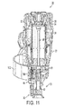
- a workpiece contact element 38 is initially pressed against a workpiece 40. More specifically, the workpiece contact element 38 includes a lower element 42 configured to be disposed on contact with the workpiece 40, and an upper linkage member 44 connected to the lower element and slidably mounted in a reciprocal manner in a channel 45 ( FIG. 11 ) in the nosepiece 23.
- a guide member 46 is fixedly mounted upon the housing 22 to guide an upper free end distal portion 48 of the upper linkage member 44 during its movement with respect to the housing.
- a control valve assembly 50 is mounted upon the tool housing 22 as is well known in the art to initiate actuation of the fastener-driving tool 20 when the control valve assembly is actuated as described below.
- the control valve assembly 50 includes a valve member 52 having a valve stem 54 that is seated upon a valve seat 56 and biased to a closed position by a spring 58.
- the valve stem 54 is configured to be engaged by an actuation lever 60 of a trigger assembly 62 to initiate actuation of the tool 20.
- the actuation lever 60 is movably connected to the trigger assembly 62 and moves between a first position or rest position ( FIG. 2 ) and a second position or activated position ( FIG. 3 ).
- a bias member, such as coil spring 64 is preferably attached between the actuation lever 60 and the trigger assembly 62 and biases the actuation lever to the rest position.
- the trigger assembly 62 includes a trigger 66 which has a hollow housing structure 68 with a pair of oppositely disposed side walls 70 ( FIG. 4 ) for accommodating the actuation lever 60 and the coil spring 64.
- the sidewalls 70 have connecting holes 72 that are aligned with holes on the housing 22 and are joined by a trigger pivot pin 76 that is secured to the housing by a lock washer 77 for pivotably connecting the trigger 66 to the housing.
- the sidewalls 70 further include openings or holes 74 that are aligned with an opening on the actuation lever 60 and receive a lever pivot pin 79 for pivotably mounting the actuation lever to the trigger 66.
- the feeder mechanism 82 Upon actuation, as the trigger 66 causes opening of the control valve 52, the piston 34 and the driver blade 36 are driven through the cylinder 28 to drive a fastener 78 fed into a drive channel 80 in the nosepiece 23 by a feeder mechanism 82.
- the feeder mechanism 82 sequentially feeds fasteners 78, which are held in a fastener support such as collation 84, to the drive channel 80.
- the feeder mechanism 82 includes a cylindrical wall 90 configured to receive a conduit or tube (not shown) for providing compressed air to a feed cylinder 92.
- the conduit diverts power source gas, i.e., pressurized air, from the drive cylinder 28, into the feed cylinder 92 and against a feed piston 96 to move the feed piston, an associated piston rod 98, and a feed pawl 100 from an advanced position ( FIG. 5 ) to a retracted position ( FIG. 6 ).
- power source gas i.e., pressurized air
- the feeder mechanism 82 also includes a fastener magazine 102, which in the illustrated embodiment is a coil-type magazine, including a fixed portion 104 and a pivotable portion 106 as described in U.S. Patent No. 8,276,798 . It should be appreciated that the feeder mechanism may be any suitable feeder mechanism used with powered-fastener driving tools.
- the fixed portion 104 is fixed to the housing 22, typically the handle 24, via an arm 108. Further, an arm 110 ( FIG.
- the feeder mechanism 82 includes the feed cylinder 92, which has the cylindrical wall 90, an end 114, and an annular O-ring 116 fixed within the cylindrical wall 90 at an outer, apertured end 118 of the feed cylinder.
- the feed piston 96 is movable within the cylindrical wall 90 between the retracted position ( FIG. 6 ) and the advanced position ( FIG. 5 ), and is provided with the piston rod 98. Sealed by the O-ring 116 and guided by the apertured end 118, the piston rod 98 moves commonly with the feed piston 96.
- a return spring 120 which is seated against the end 114 as will be described in greater detail below, and which biases the feed piston 96 toward the advanced position ( FIG. 5 ).
- An O-ring 122 is seated in a peripheral groove 124 of the feed piston 96 and seals against the cylindrical wall 90 as the feed piston 96 reciprocates within the feed cylinder 92.
- the feed pawl 100 which is mounted to the piston rod 98, is commonly movable with the piston rod 98 and the feed piston 96 between the retracted and advanced positions.
- the fasteners 78 are pre-mounted individually in fastener compartments 130 of the collation 84 having upper tabs 132 and lower tabs 134 that are movably or hingedly connected to an elongated support wall 136. Both the upper and lower tabs 132, 134 are movable between a ([-shaped) support position, in which the upper and lower tabs extend transversely from the support wall 136, and a release position in which at least one of the upper and lower tabs are generally aligned with the support wall 136.
- each of the upper and lower tabs 132, 134 respectively include pairs of upper and lower arms 138 and 140 where each of the pairs of upper and lower arms define upper and lower fastener slots 142 and 144 therebetween.
- the upper fastener slots 142 defined between the upper arms 138 and the lower fastener slots 144 defined between the lower arms 140 are aligned with each other along a longitudinal axis so that the fasteners 78 can be readily inserted, mounted in, and restrained by the aligned upper and lower fastener slots.
- the fasteners 78 are mounted in the coil-type collation 84 that includes a plurality of fasteners to be fed into the drive channel 80 of the tool 20.
- the feed pawl 100 of the feeder mechanism 82 sequentially indexes the collation 84 until the nearest lower tab 134 of the next fastener compartment 130 contacts an inner, vertical surface 25 ( FIGs. 5 and 6 ) of the nosepiece 23 to stop further movement of the collation.
- the fastener 78 in the fastener compartment 130 is driven through the nosepiece 23, the lower tabs 134 of the fastener compartment 130 are pushed downwardly by the fastener 78 and moved to the release position (see FIGs. 2 and 3 ). This allows the empty fastener compartment to pass through a drive slot 27 ( FIG. 8 ) in the nosepiece 23 to index the collation to the next fastener compartment 130 as described above.
- the feed pawl 100 has a protruding end 146 ( FIG. 5 ), which is configured for engaging a groove 148 ( FIG. 3 ) defined between adjacent fastener compartments 130 in the collation 84 when the feed pawl is in the operative position and for advancing the collation when the feed piston 96, the piston rod 98, and the feed pawl 100 are moved by spring pressure from the retracted position ( FIG. 6 ) to the advanced position ( FIG. 5 ). To allow the feed pawl 100 to move or slide over an outer surface 150 ( FIGs.
- the end 146 of the feed pawl includes an angled camming surface 152 configured for camming or sliding over the outer surface 150 of the collation 84 to the next groove 148 when the feed pawl 100 moves from the advanced position to the retracted position.
- the collation 84 should remain generally in contact with an inner wall 154 of the feed track 156 of the magazine 102 as shown in FIG. 5 so that the feed pawl 100 can engage the grooves 148 and sequence or index the collation.
- a fastener tensioning mechanism such as backup pawl 158 is mounted on an opposing side 160 of the collation 84 from the feeder mechanism 82.
- the backup pawl 158 includes a housing 162 and a tensioning post 164 movably connected to the housing 162 where the post is movable between an extended position and a retracted position.
- the tensioning post 164 includes an annular groove 166 and a spring 168 positioned in the groove 166 for biasing the post to the extended position.
- An outer end 170 of the post 164 has a rounded shape and is configured for engaging adjacent upper arms 138 of the fastener compartments 130 in the collation 84 to apply pressure to the arms 138 and press a rear surface 172 ( FIG. 8 ) of the support wall 136 of the collation against the inner wall 154 of the feed track 156 of the magazine 102 to maintain sufficient contact between the collation 84 and the feed pawl 100.
- the present tool 20 is actuated by initially pressing the workpiece contact element 38 against the workpiece 40. such as a sheet of drywall, which causes the workpiece contact element to move upwardly along the nosepiece 23 and contact and move the actuation lever 60 in the trigger 66 to the actuated position.
- the trigger 66 is depressed i.e., moved from the rest position to the actuated position, causing the actuation lever 60 to move or pivot and contact and move the valve stem 54 to the activated position.
- the tool 20 When the valve stem 54 moves to the activated position, the tool 20 is activated, and a designated amount of the compressed fluid (pressurized air) from the reservoir 26 enters the upper end of the housing 22 and pushes against the cylinder 28 to drive the fastener driving assembly, and more specifically, the piston 34 and the driver blade 36 downwardly through the cylinder and into engagement with a fastener 78 in the drive track or drive channel 80 of the nosepiece 23.
- the piston 34 returns to the top of the cylinder 28 and the feeder mechanism 82 feeds the next fastener into the drive track 80 and the above steps are repeated.
- the operator maintains the trigger in the actuated position, and fasteners are driven each time the workpiece contact element 38 contacts the workpiece.
- a tool operator In the field, a tool operator typically drives fasteners into a workpiece at a rapid pace to quickly secure the workpiece, such as a drywall sheet, in position on an underlying frame. The operator therefore continues to actuate the powered fastener tool and drive fasteners into the dywall sheet until there are no fasteners remaining in the magazine. Because it is too time consuming to constantly check the fastener magazine to see how many fasteners remain in the magazine, the operator typically initially discovers that the magazine is empty when they actuate the tool without any fasteners remaining in the magazine, commonly known as "dry-firing" or “mis-firing" the tool. As a result, a fastener is not driven into the drywall sheet.
- the driver blade is configured to extend past the end of the nosepiece of to tool to recess the fasteners.
- the present tool 20 includes an actuation lock-out mechanism 176 that is positioned adjacent to the magazine 102, is associated with the workpiece contact element 38 and the magazine 102, and is movably connected to the nosepiece 23.
- the actuation lock-out mechanism 176 includes a generally planar lever 178 including a first end 180 and an opposing second end 182.
- the first end 178 includes a first post 184 that is integrally formed with the lever 178 and protrudes from a side of the lever.
- the second end 182 includes a second post 186 and a stop arm 188, where the second post extends from a common side of the lever as the first post 184, and the stop arm 188 extends transversely from the second post 186. Also, the posts 184, 186 extend along parallel axes. In between the first post 184 and the second post 186 is a through-hole 190 configured to receive a pivot pin 192 that is inserted through the through-hole and secured in a pair of spaced ears (not shown) each having a corresponding opening 194 in the nosepiece 23. The lever 178 moves or pivots about the pivot pin 192 as best shown in FIGs. 8 and 13 .
- a bias member such as coil spring 196 ( FIG. 9 ) is positioned between the nosepiece 23 and the first post 184 to bias the lever 178 from a first, collating position to a second, blocking position.
- the coil spring 196 has a size and shape that corresponds to the size and shape of the first post 184 such that the first post is inserted at least partially into a central through-hole 198 defined by the coil spring 196 to seat the spring in place.
- the second post 186 has a generally rounded outer, camming surface 200 that extends through a corresponding opening 194 in the nosepiece 23 and contacts the outer surface 150 of the collation 84.
- the second post 186 moves or slides along the outer surface 150 of the collation until the last fastener compartment 130 passes the opening 202.
- the backup pawl 158 no longer engages the collation 84 to hold it against the inner wall 174 of the magazine 102.
- the force of the coil spring 196 on the first end 180 of the lever 178 overcomes the negligible force of the collation 84 against the second post 186.
- the movement of the lever 178 from the collating position to the blocking position simultaneously moves the stop arm 188 into the channel 45 ( FIG. 14 ) through which a linkage portion of the workpiece contact element 38 moves relative to the housing 22.
- the stop arm 188 now blocks or stops the upward movement of the workpiece contact element 38 when it is pressed against the workpiece 40.
- the workpiece contact element 38 cannot contact the actuation lever 60 as described above to move the actuation lever into a position to engage the valve stem 54 when the trigger 66 is depressed, thereby preventing actuation of the tool 20 when no fasteners 78 remain in the magazine 102.
- the tool 20 will not actuate and drive a fastener 78 until another fastener collation 84 is loaded into the magazine 102, regardless of the number of times that the operator depresses or activates the trigger 66.
- the operator loads another collation 84 having fasteners 78 into the magazine 102 so that the front end of the collation contacts the camming surface 200 of the second post 186 and pushes the second post inwardly against the force of the spring 196 to the collating position as shown in FIGs. 8 and 9 .
- the operator may now use the fastener driving tool 20 again as described above to drive fasteners 78 into workpieces such as the drywall sheet until there are no fasteners remaining in the collation 84.
Abstract
Description
- The present disclosure relates generally to powered, fastener-driving tools, wherein the tools may be electrically powered, pneumatically powered, combustion powered, or powder activated, and more particularly to a lockout mechanism for a fastener-driving tool that prevents actuation of the tool when there are no fasteners remaining in a collation in the tool magazine.
- Powered, fastener-driving tools, of the type used to drive various fasteners, such as, for example, staples, nails, and the like, typically include a housing, a power source, a supply of fasteners held in a collation, a trigger mechanism for initiating the actuation of the tool, and a workpiece-contact element (also referred to herein as a "workpiece contacting-element" or "WCE"). The workpiece-contact element is configured for engaging or contacting a workpiece, and is operatively connected to the trigger mechanism. When the workpiece-contacting element is in contact with the workpiece, and depressed or moved inwardly a predetermined amount with respect to the tool housing, as a result of the tool being pressed against or moved toward the workpiece a predetermined amount, the trigger mechanism will be enabled to initiate fastener driving. Upon actuation of the tool, a piston including a driver blade is driven through a cylinder in the housing and into a drive channel loaded with a fastener. The driver blade contacts and drives the fastener into the workpiece.
- Many fastener-driving tools include depth of drive adjustment mechanisms that adjust the depth in which the fasteners are driven into the workpiece. For example, fasteners may be driven into a workpiece so that the heads of the fasteners are flush with the outer surface of the workpiece. Alternatively, the depth of drive mechanism is adjustable so that the fasteners are recessed or driven to a designated distance in the workpiece and the heads of the fasteners are a designated distance below the outer surface of the workpiece. Recessing the fasteners is preferred in some circumstances, such as when attaching drywall to wood studs or other supports, so that the fastener heads can be covered and hidden with a drywall patching or joint compound, or other suitable setting compound.
- On a job site, it is often difficult to tell when the fastener magazine is empty or near empty. Typically, a user finds out that the tool magazine is empty when the tool is "dry fired," i.e., actuated without a fastener loaded in the fastener drive channel. This is particularly a problem when attaching drywall, because the driver blade extends outwardly from the end of the workpiece contact element to recess the fasteners in the drywall, and thereby makes a mark or hole in the drywall when the tool is dry-fired. As a result, extra time and materials are needed to repair the inadvertent holes and damage to the drywall.
- Accordingly, there is a need for a fastener-driving tool designed to prevent actuation of the tool when there are no fasteners remaining in the magazine.
- The present invention relates generally to powered, fastener-driving tools, wherein the tools may be electrically powered, pneumatically powered, combustion powered, or powder activated, and more particularly to an actuation lockout mechanism for a fastener-driving tool that prevents actuation of the tool when there are no fasteners remaining in the tool magazine.
- In an embodiment, a fastener-driving tool is provided where the tool includes a housing, a power source associated with the housing and including a reciprocating driver blade, a tool nose connected to the housing and configured for receiving the driver blade for driving fasteners fed into the nose for each actuation of the tool, a magazine configured to house a collation including a plurality of the fasteners, and a workpiece contact element movably connected to the nose. The workpiece contact element is movable between a rest position and an actuated position. When the workpiece contact element is pressed against a workpiece, the workpiece contact element moves to the actuated position. A lockout mechanism is operatively associated with the workpiece contact element and the magazine, and is movable between a first position and a second position where the lockout mechanism is biased to the second position. In operation, the lockout mechanism is in contact with the collation in the first position when fasteners are in the magazine, and moves to the second position when a last one of the fasteners in the collation has been driven by the driver blade. Also, when the actuation lockout mechanism is in the second position, the lockout mechanism blocks the movement of the workpiece contact element to the actuated position.
- In another embodiment, a fastener-driving tool is provided and includes a housing, a power source associated with the housing and including a reciprocating driver blade, a tool nose connected to the housing and configured for receiving the driver blade for driving fasteners fed into the nose for each actuation of the tool, a magazine configured to house a collation including a plurality of the fasteners and disposed for sequentially feeding fasteners to the nose, a workpiece contact element movably connected to the nose, the workpiece contact element being movable between a rest position and an actuated position, when the workpiece contact element is pressed against a workpiece, and a trigger movably connected to the housing and being movable between a rest position and an activated position. Actuation of the tool is enabled when the workpiece contact element is moved to the actuated position and the trigger is moved to the activated position. A lockout lever is pivotably connected to the housing and is movable between a first position and a second position, where the lockout lever is biased to the second position. In operation, the lever is in contact with the collation in the first position during each actuation of the tool and moves to the second position when a last one of the fasteners in the collation has been driven by the driver blade. Also, in the second position, the lever blocks movement of the workpiece contact element to the actuated position and thereby prevents subsequent actuations of the tool when the trigger is moved to the activated position.
- Any one of the embodiments mentioned above may comprise one, two or more of the following features:
- the tool further comprises a feeder mechanism movably connected to said housing and positioned on a first side of the collation, said feeder mechanism being configured for sequentially feeding each of said fasteners into said nose;
- the tool further comprises a backup mechanism movably connected to said housing and positioned on an opposing second side of said collation, said backup mechanism being biased against the collation;
- said lockout mechanism includes a lever pivotably connected to said housing and including a first end and a second end, said first end having a first post and a blocking member and said second end having a second post, wherein said blocking member blocks said workpiece contact element from moving to said actuating position when said lever is in said second position;
- the tool further comprises a spring positioned between said second post and said nose for biasing said lever to said second position;
- said tool comprises an actuation lever movably connected to said trigger and positioned adjacent to an end of said workpiece contact element, said actuation lever being movable from a rest position to an activated position when said workpiece contact element contacts said actuation lever upon depression of said workpiece contact element on a workpiece;
- the tool further comprises a control valve including an actuating pin, said actuating pin being activated when said actuation lever moves to said activated position and engages said actuating pin in each actuation of the tool;
- the tool further comprises a feeder mechanism movably connected to said nose and positioned on a first side of said collation, said feeder mechanism being configured for sequentially feeding each of said fasteners into said nose;
- said feeder mechanism includes a feed pawl and a reciprocating feed cylinder connected to said feed pawl, said feed cylinder causing said feed pawl to move between a retracted position and an advanced position;
- the tool further comprises a backup mechanism movably connected to said nose and positioned on an opposing second side of said collation, said backup mechanism being biased against said collation;
- said lockout mechanism includes a lever pivotably connected to said nose and including a first end and a second end, said first end having a first post and a blocking member and said second end having a second post, wherein said blocking member blocks said workpiece contact element from moving to said actuating position when said lever is in said second position;
- the tool further comprises a spring positioned between said second post and said housing for biasing said lever to said second position;
- said first post and said second post are on a common side of said lever;
- said magazine is a coil magazine.
-
-
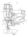
FIG. 1 is a perspective view of the present fastener driving tool including an actuation lockout mechanism; -
FIG. 2 is a vertical cross-sectional view of the fastener driving tool ofFIG. 1 , where the workpiece contact element has been depressed against a workpiece and the trigger has not been depressed or actuated; -
FIG. 3 is a cross-sectional view of the fastener driving tool ofFIG. 1 , where the workpiece contact element has been depressed against a workpiece and the trigger has been depressed or actuated by a user; -
FIG. 4 is an enlarged, fragmentary view of the workpiece contact element assembly and the trigger assembly of the fastener driving tool ofFIG. 1 ; -
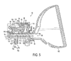
FIG. 5 is a cross-sectional view taken along the line 5-5 ofFIG. 1 in the direction generally indicated, where the feed pawl is in an extended state for feeding a fastener into the drive channel of the nosepiece; -
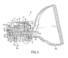
FIG. 6 is a cross-sectional view similar toFIG. 5 where the feed pawl is in a retracted state for indexing the collation in the feed track; -
FIG. 7A is a perspective view of the lever of the present actuation lockout mechanism; -
FIG. 7B is a bottom view of the lever of the actuation lockout mechanism ofFIG. 7A ; -
FIG. 7C is a rear view of the lever of the actuation lockout mechanism ofFIG. 7A ; -
FIG. 7D is a top view of the lever of the actuation lockout mechanism ofFIG. 7A ; -
FIG. 7E is a front view of the lever of the actuation lockout mechanism ofFIG. 7A ; -
FIG. 7F is a left side view of the lever of the actuation lockout mechanism ofFIG. 7A ; -
FIG. 7G is a right side view of the lever of the actuation lockout mechanism ofFIG. 7A ; -
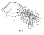
FIG. 8 is a perspective cross-sectional view taken along the line 8-8 ofFIG. 1 ; -
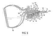
FIG. 9 is a top cross-sectional view of the feeder mechanism ofFIG. 8 where the collation includes a plurality of fasteners; -
FIG. 10 is a top cross-sectional view of the feeder mechanism ofFIG. 8 , where there is only one fastener remaining in the collation; -
FIG. 11 is a front cross-section taken along the line 11-11 ofFIG. 1 and in the direction generally indicated, where the present actuation lockout mechanism is in a not in the lock out position; -
FIG. 12 is a top cross-sectional view of the feeder mechanism ofFIG. 8 where there are no fasteners remaining in the collation; -
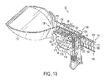
FIG. 13 is a top perspective cross-sectional view of the feeder mechanism ofFIG. 12 ; and -
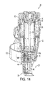
FIG. 14 is a front cross-section taken along the line 11-11 ofFIG. 1 and in the direction generally indicated, where the present actuation lockout mechanism is in the lock out position. - Referring now to
FIGs. 1-14 , a fastener driving tool of the type suitable with the present actuation lockout mechanism is generally designated 20 and is depicted as a pnuematic-powered tool. The general principles of operation of such tools are known in the art, examples of which is described inU.S. Patent Application Publication No. 2012/0223120-A1 . However, it is contemplated that the present actuation lockout mechanism is applicable to fastener driver tools powered by other power sources that employ a reciprocating driver blade for driving fasteners into a workpiece, such as electrically powered, combustion powered, or powder activated fastener driving tools. - Referring now to
FIGs. 1-4 , the pneumaticfastener driving tool 20 includes ahousing 22 connected to a nose ornosepiece 23, the housing including a generally vertically extending head or forward portion and a rearwardly extendinghollow handle 24 having a cavity defining afluid reservoir 26. Pressurized fluid, such as compressed air, is supplied to thefluid reservoir 26 of the tool by a suitable flexible line (not shown). The drive system for thetool 20 includes a main orpower cylinder 28 mounted within the head portion of thehousing 22 and having an openupper end 30 that is configured to be selectively connected to thereservoir 26 as is known in the art (seeFIGs. 2 and3 ). Afastener driving assembly 32 is slidably and reciprocably mounted in thecylinder 28 and includes a main or drivepiston 34 and adriver blade 36 connected to and depending from the piston. - To initiate an actuation of the tool, 20, a
workpiece contact element 38 is initially pressed against aworkpiece 40. More specifically, theworkpiece contact element 38 includes alower element 42 configured to be disposed on contact with theworkpiece 40, and anupper linkage member 44 connected to the lower element and slidably mounted in a reciprocal manner in a channel 45 (FIG. 11 ) in thenosepiece 23. Aguide member 46 is fixedly mounted upon thehousing 22 to guide an upper free enddistal portion 48 of theupper linkage member 44 during its movement with respect to the housing. - A
control valve assembly 50 is mounted upon thetool housing 22 as is well known in the art to initiate actuation of the fastener-drivingtool 20 when the control valve assembly is actuated as described below. As shown inFIGs. 2 and3 , thecontrol valve assembly 50 includes avalve member 52 having avalve stem 54 that is seated upon avalve seat 56 and biased to a closed position by aspring 58. The valve stem 54 is configured to be engaged by anactuation lever 60 of atrigger assembly 62 to initiate actuation of thetool 20. Specifically, theactuation lever 60 is movably connected to thetrigger assembly 62 and moves between a first position or rest position (FIG. 2 ) and a second position or activated position (FIG. 3 ). A bias member, such ascoil spring 64, is preferably attached between theactuation lever 60 and thetrigger assembly 62 and biases the actuation lever to the rest position. - Referring now to
FIGs. 2-4 , thetrigger assembly 62 includes atrigger 66 which has ahollow housing structure 68 with a pair of oppositely disposed side walls 70 (FIG. 4 ) for accommodating theactuation lever 60 and thecoil spring 64. Thesidewalls 70 have connectingholes 72 that are aligned with holes on thehousing 22 and are joined by atrigger pivot pin 76 that is secured to the housing by alock washer 77 for pivotably connecting thetrigger 66 to the housing. Thesidewalls 70 further include openings or holes 74 that are aligned with an opening on theactuation lever 60 and receive alever pivot pin 79 for pivotably mounting the actuation lever to thetrigger 66. - Upon actuation, as the
trigger 66 causes opening of thecontrol valve 52, thepiston 34 and thedriver blade 36 are driven through thecylinder 28 to drive afastener 78 fed into adrive channel 80 in thenosepiece 23 by afeeder mechanism 82. Thefeeder mechanism 82 sequentiallyfeeds fasteners 78, which are held in a fastener support such ascollation 84, to thedrive channel 80. Referring now toFIGs. 5 ,6 and8-10 , thefeeder mechanism 82 includes acylindrical wall 90 configured to receive a conduit or tube (not shown) for providing compressed air to afeed cylinder 92. Specifically, the conduit diverts power source gas, i.e., pressurized air, from thedrive cylinder 28, into thefeed cylinder 92 and against afeed piston 96 to move the feed piston, an associatedpiston rod 98, and afeed pawl 100 from an advanced position (FIG. 5 ) to a retracted position (FIG. 6 ). - Referring now to
FIGs. 1-3 , thefeeder mechanism 82 also includes afastener magazine 102, which in the illustrated embodiment is a coil-type magazine, including a fixedportion 104 and apivotable portion 106 as described inU.S. Patent No. 8,276,798 . It should be appreciated that the feeder mechanism may be any suitable feeder mechanism used with powered-fastener driving tools. The fixedportion 104 is fixed to thehousing 22, typically thehandle 24, via anarm 108. Further, an arm 110 (FIG. 1 ) pivotably connects thepivotable portion 106 to the fixedportion 104 where thearm 110 is hinged to the fixed portion via ahinge 112 or other suitable pivoting connector, and is pivotable between an opened position (not shown) for loading fasteners, and a closed position (seeFIG. 1 ). - In
FIGs. 1 ,5 and6 , thefeeder mechanism 82 includes thefeed cylinder 92, which has thecylindrical wall 90, anend 114, and an annular O-ring 116 fixed within thecylindrical wall 90 at an outer,apertured end 118 of the feed cylinder. Thefeed piston 96 is movable within thecylindrical wall 90 between the retracted position (FIG. 6 ) and the advanced position (FIG. 5 ), and is provided with thepiston rod 98. Sealed by the O-ring 116 and guided by theapertured end 118, thepiston rod 98 moves commonly with thefeed piston 96. - Inside the
feed cylinder 92 is areturn spring 120 which is seated against theend 114 as will be described in greater detail below, and which biases thefeed piston 96 toward the advanced position (FIG. 5 ). An O-ring 122 is seated in aperipheral groove 124 of thefeed piston 96 and seals against thecylindrical wall 90 as thefeed piston 96 reciprocates within thefeed cylinder 92. Thefeed pawl 100, which is mounted to thepiston rod 98, is commonly movable with thepiston rod 98 and thefeed piston 96 between the retracted and advanced positions. - Referring to
FIGs. 2 ,3 ,5 and6 , thefasteners 78 are pre-mounted individually infastener compartments 130 of thecollation 84 havingupper tabs 132 andlower tabs 134 that are movably or hingedly connected to anelongated support wall 136. Both the upper andlower tabs support wall 136, and a release position in which at least one of the upper and lower tabs are generally aligned with thesupport wall 136. - As shown in
FIG. 2 , each of the upper andlower tabs lower arms lower fastener slots upper fastener slots 142 defined between theupper arms 138 and thelower fastener slots 144 defined between thelower arms 140 are aligned with each other along a longitudinal axis so that thefasteners 78 can be readily inserted, mounted in, and restrained by the aligned upper and lower fastener slots. - In the illustrated embodiment, the
fasteners 78 are mounted in the coil-type collation 84 that includes a plurality of fasteners to be fed into thedrive channel 80 of thetool 20. As described below, after each actuation of thetool 20, thefeed pawl 100 of thefeeder mechanism 82 sequentially indexes thecollation 84 until the nearestlower tab 134 of thenext fastener compartment 130 contacts an inner, vertical surface 25 (FIGs. 5 and6 ) of thenosepiece 23 to stop further movement of the collation. When thefastener 78 in thefastener compartment 130 is driven through thenosepiece 23, thelower tabs 134 of thefastener compartment 130 are pushed downwardly by thefastener 78 and moved to the release position (seeFIGs. 2 and3 ). This allows the empty fastener compartment to pass through a drive slot 27 (FIG. 8 ) in thenosepiece 23 to index the collation to thenext fastener compartment 130 as described above. - More specifically, the
feed pawl 100 has a protruding end 146 (FIG. 5 ), which is configured for engaging a groove 148 (FIG. 3 ) defined betweenadjacent fastener compartments 130 in thecollation 84 when the feed pawl is in the operative position and for advancing the collation when thefeed piston 96, thepiston rod 98, and thefeed pawl 100 are moved by spring pressure from the retracted position (FIG. 6 ) to the advanced position (FIG. 5 ). To allow thefeed pawl 100 to move or slide over an outer surface 150 (FIGs. 8 and9 ) of thecollation 84, theend 146 of the feed pawl includes anangled camming surface 152 configured for camming or sliding over theouter surface 150 of thecollation 84 to thenext groove 148 when thefeed pawl 100 moves from the advanced position to the retracted position. - The
collation 84 should remain generally in contact with aninner wall 154 of thefeed track 156 of themagazine 102 as shown inFIG. 5 so that thefeed pawl 100 can engage thegrooves 148 and sequence or index the collation. Thus, a fastener tensioning mechanism such asbackup pawl 158 is mounted on anopposing side 160 of thecollation 84 from thefeeder mechanism 82. Thebackup pawl 158 includes ahousing 162 and atensioning post 164 movably connected to thehousing 162 where the post is movable between an extended position and a retracted position. - As shown in
FIGs. 5 and6 , thetensioning post 164 includes anannular groove 166 and aspring 168 positioned in thegroove 166 for biasing the post to the extended position. Anouter end 170 of thepost 164 has a rounded shape and is configured for engaging adjacentupper arms 138 of the fastener compartments 130 in thecollation 84 to apply pressure to thearms 138 and press a rear surface 172 (FIG. 8 ) of thesupport wall 136 of the collation against theinner wall 154 of thefeed track 156 of themagazine 102 to maintain sufficient contact between thecollation 84 and thefeed pawl 100. - As is the case with conventional fastener driving tools, the
present tool 20 is actuated by initially pressing theworkpiece contact element 38 against theworkpiece 40. such as a sheet of drywall, which causes the workpiece contact element to move upwardly along thenosepiece 23 and contact and move theactuation lever 60 in thetrigger 66 to the actuated position. In a sequential mode of operation, thetrigger 66 is depressed i.e., moved from the rest position to the actuated position, causing theactuation lever 60 to move or pivot and contact and move thevalve stem 54 to the activated position. When thevalve stem 54 moves to the activated position, thetool 20 is activated, and a designated amount of the compressed fluid (pressurized air) from thereservoir 26 enters the upper end of thehousing 22 and pushes against thecylinder 28 to drive the fastener driving assembly, and more specifically, thepiston 34 and thedriver blade 36 downwardly through the cylinder and into engagement with afastener 78 in the drive track or drivechannel 80 of thenosepiece 23. After the actuation of thetool 20, thepiston 34 returns to the top of thecylinder 28 and thefeeder mechanism 82 feeds the next fastener into thedrive track 80 and the above steps are repeated. In an alternative repetitive mode of operation, the operator maintains the trigger in the actuated position, and fasteners are driven each time theworkpiece contact element 38 contacts the workpiece. - In the field, a tool operator typically drives fasteners into a workpiece at a rapid pace to quickly secure the workpiece, such as a drywall sheet, in position on an underlying frame. The operator therefore continues to actuate the powered fastener tool and drive fasteners into the dywall sheet until there are no fasteners remaining in the magazine. Because it is too time consuming to constantly check the fastener magazine to see how many fasteners remain in the magazine, the operator typically initially discovers that the magazine is empty when they actuate the tool without any fasteners remaining in the magazine, commonly known as "dry-firing" or "mis-firing" the tool. As a result, a fastener is not driven into the drywall sheet. Because heads of fasteners driven into drywall sheets are recessed from the outer surface of the drywall sheet so that the fasteners can be sufficiently covered with a drywall patching joint compound, the driver blade is configured to extend past the end of the nosepiece of to tool to recess the fasteners. Thus, when the magazine is empty and the operator dry-fires the tool, the tool still drivers the driver blade through the drive track and into the drywall sheet thereby forming a hole and damaging the drywall sheet.
- Referring now to
FIGs. 7A-7G and8-14 , to overcome this problem, thepresent tool 20 includes an actuation lock-outmechanism 176 that is positioned adjacent to themagazine 102, is associated with theworkpiece contact element 38 and themagazine 102, and is movably connected to thenosepiece 23. The actuation lock-outmechanism 176 includes a generallyplanar lever 178 including afirst end 180 and an opposingsecond end 182. Thefirst end 178 includes afirst post 184 that is integrally formed with thelever 178 and protrudes from a side of the lever. Thesecond end 182 includes asecond post 186 and astop arm 188, where the second post extends from a common side of the lever as thefirst post 184, and thestop arm 188 extends transversely from thesecond post 186. Also, theposts first post 184 and thesecond post 186 is a through-hole 190 configured to receive apivot pin 192 that is inserted through the through-hole and secured in a pair of spaced ears (not shown) each having acorresponding opening 194 in thenosepiece 23. Thelever 178 moves or pivots about thepivot pin 192 as best shown inFIGs. 8 and13 . - A bias member such as coil spring 196 (
FIG. 9 ) is positioned between thenosepiece 23 and thefirst post 184 to bias thelever 178 from a first, collating position to a second, blocking position. As shown inFIG. 10 , thecoil spring 196 has a size and shape that corresponds to the size and shape of thefirst post 184 such that the first post is inserted at least partially into a central through-hole 198 defined by thecoil spring 196 to seat the spring in place. - Referring now to
FIGs. 7F and9 , and thesecond post 186 has a generally rounded outer,camming surface 200 that extends through acorresponding opening 194 in thenosepiece 23 and contacts theouter surface 150 of thecollation 84. During the indexing of thecollation 84, thesecond post 186 moves or slides along theouter surface 150 of the collation until thelast fastener compartment 130 passes the opening 202. At this point, thebackup pawl 158 no longer engages thecollation 84 to hold it against the inner wall 174 of themagazine 102. Thus, the force of thecoil spring 196 on thefirst end 180 of thelever 178 overcomes the negligible force of thecollation 84 against thesecond post 186. At this point, thecollation 84 is not tensioned and therefore falls away from the tool, and thelever 178 is now able to move or pivot from the collating position to the blocking position and causes thesecond post 186 to move through theopening 194 and into themagazine 102 as shown inFIGs. 12-14 . - Referring now to
FIGS. 13 and14 , the movement of thelever 178 from the collating position to the blocking position simultaneously moves thestop arm 188 into the channel 45 (FIG. 14 ) through which a linkage portion of theworkpiece contact element 38 moves relative to thehousing 22. Once it extends into the channel, thestop arm 188 now blocks or stops the upward movement of theworkpiece contact element 38 when it is pressed against theworkpiece 40. As a result, theworkpiece contact element 38 cannot contact theactuation lever 60 as described above to move the actuation lever into a position to engage thevalve stem 54 when thetrigger 66 is depressed, thereby preventing actuation of thetool 20 when nofasteners 78 remain in themagazine 102. Subsequently, thetool 20 will not actuate and drive afastener 78 until anotherfastener collation 84 is loaded into themagazine 102, regardless of the number of times that the operator depresses or activates thetrigger 66. - To enable actuation of the
tool 20 after themagazine 102 is empty, i.e., thefasteners 78 in thecollation 84 are used up, the operator loads anothercollation 84 havingfasteners 78 into themagazine 102 so that the front end of the collation contacts thecamming surface 200 of thesecond post 186 and pushes the second post inwardly against the force of thespring 196 to the collating position as shown inFIGs. 8 and9 . The operator may now use thefastener driving tool 20 again as described above to drivefasteners 78 into workpieces such as the drywall sheet until there are no fasteners remaining in thecollation 84. - While a particular embodiment of the present actuation lockout mechanism for a powered fastener-driving tool has been described herein, it will be appreciated by those skilled in the art that changes and modifications may be made thereto without departing from the invention in its broader aspects and as set forth in the following claims.
Claims (15)
- A fastener-driving tool (20) comprising:a housing (22);a power source associated with said housing and including a reciprocating driver blade (36);a tool nose (23) connected to said housing and configured for receiving said driver blade for driving fasteners (78) fed into said nose for each actuation of the tool;a magazine (102) configured to house a collation (84) including a plurality of the fasteners;a workpiece contact element (38) movably connected to said nose, said workpiece contact element being movable between a rest position and an actuated position, upon engagement against a workpiece (40); anda lockout mechanism (176) is operatively associated with the workpiece nose contact element and the magazine and is movable between a first position and a second position, said lockout mechanism being biased to said second position, wherein said lockout mechanism is in contact with the collation in said first position when fasteners are in the magazine and moves to said second position when a last one of the fasteners in the collation has been driven by said driver blade, and wherein in said second position, said lockout mechanism blocks said workpiece contact element to prevent said workpiece contact element from moving to said actuated position.
- The tool (20) of claim 1, further comprising a feeder mechanism (82) movably connected to said housing (22) and positioned on a first side of the collation (84), said feeder mechanism being configured for sequentially feeding each of said fasteners (78) into said nose.
- The tool (20) of claim 1 or 2, further comprising a backup mechanism (158) movably connected to said housing (22) and positioned on an opposing second side of said collation (84), said backup mechanism being biased against the collation.
- The tool (20) of any one of claims 1 to 3, wherein said lockout mechanism (176) includes a lever (178) pivotably connected to said housing (22) and including a first end (180) and a second end (182), said first end having a first post (184) and a blocking member and said second end having a second post (186), wherein said blocking member blocks said workpiece contact element (38) from moving to said actuating position when said lever is in said second position.
- The tool of claim 4, further comprising a spring (196) positioned between said second post (182) and said nose (23) for biasing said lever (178) to said second position.
- A fastener-driving tool (20) comprising:a housing (22);a power source associated with said housing and including a reciprocating driver blade (36);a tool nose (23) connected to said housing and configured for receiving said driver blade for driving fasteners (78) fed into said nose for each actuation of the tool;a magazine (102) configured to house a collation (84) including a plurality of the fasteners and disposed for sequentially feeding fasteners to the nose;a workpiece contact element (38) movably connected to said nose, said being movable between a rest position and an actuated position, when said workpiece contact element is pressed against a workpiece (40);a trigger (66) movably connected to said housing and being movable between a rest position and an activated position wherein actuation of the tool occurs when said workpiece contact element is moved to said actuated position and said trigger is moved to said activated position; anda lockout lever (178) pivotably connected to said nose (23) and being movable between a first position and a second position, said lockout lever being biased to said second position, wherein said lever is in contact with the collation in said first position when the fasteners are in said nose, and moves to said second position when a last one of the fasteners in the collation has been driven by said driver blade, and wherein in said second position, said lever blocks movement of said workpiece contact element to said actuated position and thereby prevents subsequent actuations of the tool when said trigger is moved to said activated position.
- The tool (20) of claim 6, further comprising an actuation lever (60) movably connected to said trigger (66) and positioned adjacent to an end of said workpiece contact element (38), said actuation lever being movable from a rest position to an activated position when said workpiece contact element contacts said actuation lever upon depression of said workpiece contact element on a workpiece (40).
- The tool (20) of claim 7, further comprising a control valve (50) including an actuating pin, said actuating pin being activated when said actuation lever (60) moves to said activated position and engages said actuating pin in each actuation of the tool.
- The tool (20) of any one of claims 6 to 8, further comprising a feeder mechanism (82) movably connected to said nose (23) and positioned on a first side of said collation (84), said feeder mechanism being configured for sequentially feeding each of said fasteners (78) into said nose (23).
- The tool (20) of claim 9, further comprising a backup mechanism movably connected to said nose (23) and positioned on an opposing second side of said collation (84), said backup mechanism being biased against said collation.
- The tool (20) of any one of claims 6 to 10, wherein said lockout lever (178) is pivotably connected to said nose (23) and includes a first end (180) and a second end (182), said first end having a first post (184) and a blocking member and said second end having a second post (186). wherein said blocking member blocks said workpiece contact element (38) from moving to said actuating position when said lever is in said second position.
- The tool (20) of claim 11, further comprising a spring (196) positioned between said second post (182) and said housing (22) for biasing said lever (178) to said second position.
- The tool (20) of claim 2, 9 or 10, wherein said feeder mechanism (82) includes a feed pawl (100) and a reciprocating feed cylinder (92) connected to said feed pawl, said feed cylinder causing said feed pawl to move between a retracted position and an advanced position.
- The tool (20) of claim 4, 5, 11 or 12, wherein said first post (180) and said second post (182) are on a common side of said lever (178).
- The tool (20) of any one claims 1 to 14, wherein said magazine (102) is a coil magazine.
Applications Claiming Priority (1)
| Application Number | Priority Date | Filing Date | Title |
|---|---|---|---|
| US13/792,783 US9636811B2 (en) | 2013-03-11 | 2013-03-11 | Actuation lockout for a fastener-driving tool |
Publications (2)
| Publication Number | Publication Date |
|---|---|
| EP2781307A1 true EP2781307A1 (en) | 2014-09-24 |
| EP2781307B1 EP2781307B1 (en) | 2016-06-01 |
Family
ID=50238170
Family Applications (1)
| Application Number | Title | Priority Date | Filing Date |
|---|---|---|---|
| EP14157638.9A Active EP2781307B1 (en) | 2013-03-11 | 2014-03-04 | An actuation lockout for a fastener-driving tool |
Country Status (3)
| Country | Link |
|---|---|
| US (1) | US9636811B2 (en) |
| EP (1) | EP2781307B1 (en) |
| CA (1) | CA2842933C (en) |
Cited By (2)
| Publication number | Priority date | Publication date | Assignee | Title |
|---|---|---|---|---|
| WO2016115705A1 (en) * | 2015-01-22 | 2016-07-28 | Techtronic Industries Company Limited | Power tools containing locking mechanisms and method of engaging such locking mechanisms |
| WO2021236940A1 (en) * | 2020-05-22 | 2021-11-25 | Milwaukee Electric Tool Corporation | Dry-fire lockout and last fastener retention mechanism for powered fastener driver |
Families Citing this family (9)
| Publication number | Priority date | Publication date | Assignee | Title |
|---|---|---|---|---|
| TWI481482B (en) * | 2013-10-07 | 2015-04-21 | Basso Ind Corp | A nail is not a nail |
| US11400572B2 (en) * | 2016-06-30 | 2022-08-02 | Black & Decker, Inc. | Dry-fire bypass for a fastening tool |
| US11141845B2 (en) | 2017-02-02 | 2021-10-12 | Illinois Tool Works Inc. | Combustion-powered tool with sleeve-retaining lockout device |
| EP3600779A2 (en) | 2017-05-03 | 2020-02-05 | Signode Industrial Group LLC | Electrically driven staple device |
| US11407094B2 (en) * | 2018-04-06 | 2022-08-09 | Black & Decker, Inc. | Fastening tool having a low nail, lockout mechanism |
| US20190329390A1 (en) * | 2018-04-30 | 2019-10-31 | Everwin Pneumatic Corporation | Nail gun with dry fire prevention device |
| EP4126460A4 (en) | 2020-03-27 | 2023-12-06 | Milwaukee Electric Tool Corporation | Powered fastener driver |
| EP4126462A1 (en) | 2020-03-31 | 2023-02-08 | Milwaukee Electric Tool Corporation | Powered fastener driver |
| US11794323B2 (en) | 2021-03-11 | 2023-10-24 | Illinois Tool Works Inc. | Fastener-driving tool with chamber member retaining assembly |
Citations (5)
| Publication number | Priority date | Publication date | Assignee | Title |
|---|---|---|---|---|
| US20050023323A1 (en) * | 2003-07-30 | 2005-02-03 | Jalbert David B. | Integrated check pawl, last nail-retaining, and dry fire lock-out mechanism for fastener-driving tool |
| EP1693160A1 (en) * | 2003-10-16 | 2006-08-23 | Max Co., Ltd. | Nailing device and magazine |
| EP1862262A1 (en) * | 2006-05-30 | 2007-12-05 | HILTI Aktiengesellschaft | Handheld fastening tool |
| US20120223120A1 (en) | 2011-03-01 | 2012-09-06 | Illinois Tool Works Inc. | Valve cap for pneumatic nailer |
| US8276798B2 (en) | 2007-06-21 | 2012-10-02 | Illinois Tool Works Inc. | Feeder mechanism retention device for fastener driving tool |
Family Cites Families (17)
| Publication number | Priority date | Publication date | Assignee | Title |
|---|---|---|---|---|
| US3543987A (en) * | 1968-06-12 | 1970-12-01 | Fastener Corp | Fastener driving tool |
| US3638532A (en) | 1969-06-30 | 1972-02-01 | Fastener Corp | Fastener driving tool |
| US4784308A (en) * | 1986-04-03 | 1988-11-15 | Duo-Fast Corporation | Fastener driving tool |
| DE4032200C2 (en) * | 1990-10-11 | 2000-01-20 | Hilti Ag | Setting tool for fasteners |
| JP3272750B2 (en) * | 1991-09-21 | 2002-04-08 | 株式会社マキタ | Nail guide device for nailing machine |
| AU667162B2 (en) | 1993-05-13 | 1996-03-07 | Stanley-Bostitch, Inc. | Fastener driving device particularly suited for use as a roofing nailer |
| US5626274A (en) * | 1996-02-05 | 1997-05-06 | Illinois Tool Works Inc. | Nail strip magazine with spring leaf to bias feeding member and to separate nail strips |
| DE19642295A1 (en) * | 1996-10-14 | 1998-04-16 | Hilti Ag | Powder-powered setting tool with magazine for fasteners |
| IT1299814B1 (en) * | 1998-01-09 | 2000-04-04 | Fasco Spa | COMPRESSED AIR FIXING MACHINE. |
| US6371348B1 (en) | 1999-08-06 | 2002-04-16 | Stanley Fastening Systems, Lp | Fastener driving device with enhanced sequential actuation |
| US6170730B1 (en) * | 2000-06-28 | 2001-01-09 | Basso Industry Corp. | Nail engaging device for engaging nails connected by wires and plastic plate |
| USD501383S1 (en) | 2003-05-22 | 2005-02-01 | Stanley Fastening Systems, L.P. | Nailer |
| DE10351419B4 (en) * | 2003-11-04 | 2006-04-27 | Hilti Ag | setting tool |
| JP5034177B2 (en) * | 2005-05-25 | 2012-09-26 | マックス株式会社 | Driving tool safety device |
| DE102006000064A1 (en) * | 2006-02-14 | 2007-08-16 | Hilti Ag | setting tool |
| EP2012976B1 (en) * | 2006-04-20 | 2015-09-09 | Illinois Tool Works Inc. | Fastener-driving tool having trigger control mechanism for alternatively permitting bump firing and sequential firing modes of operation |
| TW201026449A (en) * | 2009-01-05 | 2010-07-16 | Basso Ind Corp | Nail gun with safe firing mechanism |
-
2013
- 2013-03-11 US US13/792,783 patent/US9636811B2/en active Active
-
2014
- 2014-02-14 CA CA2842933A patent/CA2842933C/en active Active
- 2014-03-04 EP EP14157638.9A patent/EP2781307B1/en active Active
Patent Citations (5)
| Publication number | Priority date | Publication date | Assignee | Title |
|---|---|---|---|---|
| US20050023323A1 (en) * | 2003-07-30 | 2005-02-03 | Jalbert David B. | Integrated check pawl, last nail-retaining, and dry fire lock-out mechanism for fastener-driving tool |
| EP1693160A1 (en) * | 2003-10-16 | 2006-08-23 | Max Co., Ltd. | Nailing device and magazine |
| EP1862262A1 (en) * | 2006-05-30 | 2007-12-05 | HILTI Aktiengesellschaft | Handheld fastening tool |
| US8276798B2 (en) | 2007-06-21 | 2012-10-02 | Illinois Tool Works Inc. | Feeder mechanism retention device for fastener driving tool |
| US20120223120A1 (en) | 2011-03-01 | 2012-09-06 | Illinois Tool Works Inc. | Valve cap for pneumatic nailer |
Cited By (5)
| Publication number | Priority date | Publication date | Assignee | Title |
|---|---|---|---|---|
| WO2016115705A1 (en) * | 2015-01-22 | 2016-07-28 | Techtronic Industries Company Limited | Power tools containing locking mechanisms and method of engaging such locking mechanisms |
| CN107206580A (en) * | 2015-01-22 | 2017-09-26 | 创科实业有限公司 | Power tool including locking mechanism and the method for engaging the locking mechanism |
| AU2015378403B2 (en) * | 2015-01-22 | 2018-12-06 | Techtronic Industries Company Limited | Power tools containing locking mechanisms and method of engaging such locking mechanisms |
| WO2021236940A1 (en) * | 2020-05-22 | 2021-11-25 | Milwaukee Electric Tool Corporation | Dry-fire lockout and last fastener retention mechanism for powered fastener driver |
| US11376721B2 (en) | 2020-05-22 | 2022-07-05 | Milwaukee Electric Tool Corporation | Dry-fire lockout and last fastener retention mechanism for powered fastener driver |
Also Published As
| Publication number | Publication date |
|---|---|
| US20140252060A1 (en) | 2014-09-11 |
| CA2842933A1 (en) | 2014-09-11 |
| CA2842933C (en) | 2016-09-13 |
| US9636811B2 (en) | 2017-05-02 |
| EP2781307B1 (en) | 2016-06-01 |
Similar Documents
| Publication | Publication Date | Title |
|---|---|---|
| EP2781307B1 (en) | An actuation lockout for a fastener-driving tool | |
| US7513403B2 (en) | Idle driving operation preventing devices for fastener driving tools, and fastener driving tools having such devices | |
| USRE41265E1 (en) | Depth of drive adjustment for a fastener driving tool with removable contact member and method of exchanging contact members | |
| US6543664B2 (en) | Selectable trigger | |
| TWI239881B (en) | Fastener driving tool having contact arm in contact with workpiece | |
| US5803338A (en) | Fastener driving tool for locating a pre-existing hole in a first workpiece and driving a fastener therethrough into a second workpiece | |
| US8931676B2 (en) | Nailer having mechanism for pre-positioning nail | |
| US7455207B2 (en) | Magazine for wired-collated fasteners with automatic loading | |
| EP0591671A1 (en) | Positioning mechanism for powered fastener-driving tool | |
| EP1882557A1 (en) | Pusher bearing and pusher block for magazine feeder | |
| AU4051200A (en) | Safety trip assembly and trip lock mechanism for a fastener driving tool | |
| US20080041913A1 (en) | Pneumatic hand tool for inserting t-nuts | |
| ITBO980005A1 (en) | COMPRESSED AIR FIXING MACHINE. | |
| US7866521B2 (en) | Magazine for wired-collated fasteners with automatic loading | |
| US3858782A (en) | Pneumatic fastener driving tool | |
| US2714208A (en) | Stapling implement | |
| US2801417A (en) | Magazine closure for stapling implements | |
| JPH0616669Y2 (en) | Safety mechanism in nailer | |
| KR100722208B1 (en) | Stapler | |
| JPH0546853Y2 (en) | ||
| US20070251971A1 (en) | Nailing Machine and Magazine of Nailing Machine | |
| JP2015142954A (en) | Placing tool | |
| JP2006000987A (en) | Magazine unit for nailing machine | |
| JPH0760660A (en) | Nose mechanism for fixing tool driver | |
| JPH06198575A (en) | Nail feeder of compressed air type nailing machine |
Legal Events
| Date | Code | Title | Description |
|---|---|---|---|
| PUAI | Public reference made under article 153(3) epc to a published international application that has entered the european phase |
Free format text: ORIGINAL CODE: 0009012 |
|
| 17P | Request for examination filed |
Effective date: 20140304 |
|
| AK | Designated contracting states |
Kind code of ref document: A1 Designated state(s): AL AT BE BG CH CY CZ DE DK EE ES FI FR GB GR HR HU IE IS IT LI LT LU LV MC MK MT NL NO PL PT RO RS SE SI SK SM TR |
|
| AX | Request for extension of the european patent |
Extension state: BA ME |
|
| R17P | Request for examination filed (corrected) |
Effective date: 20150324 |
|
| RBV | Designated contracting states (corrected) |
Designated state(s): AL AT BE BG CH CY CZ DE DK EE ES FI FR GB GR HR HU IE IS IT LI LT LU LV MC MK MT NL NO PL PT RO RS SE SI SK SM TR |
|
| GRAP | Despatch of communication of intention to grant a patent |
Free format text: ORIGINAL CODE: EPIDOSNIGR1 |
|
| INTG | Intention to grant announced |
Effective date: 20151113 |
|
| GRAS | Grant fee paid |
Free format text: ORIGINAL CODE: EPIDOSNIGR3 |
|
| GRAA | (expected) grant |
Free format text: ORIGINAL CODE: 0009210 |
|
| AK | Designated contracting states |
Kind code of ref document: B1 Designated state(s): AL AT BE BG CH CY CZ DE DK EE ES FI FR GB GR HR HU IE IS IT LI LT LU LV MC MK MT NL NO PL PT RO RS SE SI SK SM TR |
|
| REG | Reference to a national code |
Ref country code: GB Ref legal event code: FG4D |
|
| REG | Reference to a national code |
Ref country code: CH Ref legal event code: EP Ref country code: AT Ref legal event code: REF Ref document number: 803579 Country of ref document: AT Kind code of ref document: T Effective date: 20160615 |
|
| REG | Reference to a national code |
Ref country code: IE Ref legal event code: FG4D |
|
| REG | Reference to a national code |
Ref country code: DE Ref legal event code: R096 Ref document number: 602014002152 Country of ref document: DE |
|
| REG | Reference to a national code |
Ref country code: SE Ref legal event code: TRGR |
|
| REG | Reference to a national code |
Ref country code: LT Ref legal event code: MG4D |
|
| REG | Reference to a national code |
Ref country code: NL Ref legal event code: MP Effective date: 20160601 |
|
| PG25 | Lapsed in a contracting state [announced via postgrant information from national office to epo] |
Ref country code: LT Free format text: LAPSE BECAUSE OF FAILURE TO SUBMIT A TRANSLATION OF THE DESCRIPTION OR TO PAY THE FEE WITHIN THE PRESCRIBED TIME-LIMIT Effective date: 20160601 Ref country code: NO Free format text: LAPSE BECAUSE OF FAILURE TO SUBMIT A TRANSLATION OF THE DESCRIPTION OR TO PAY THE FEE WITHIN THE PRESCRIBED TIME-LIMIT Effective date: 20160901 |
|
| REG | Reference to a national code |
Ref country code: AT Ref legal event code: MK05 Ref document number: 803579 Country of ref document: AT Kind code of ref document: T Effective date: 20160601 |
|
| PG25 | Lapsed in a contracting state [announced via postgrant information from national office to epo] |
Ref country code: LV Free format text: LAPSE BECAUSE OF FAILURE TO SUBMIT A TRANSLATION OF THE DESCRIPTION OR TO PAY THE FEE WITHIN THE PRESCRIBED TIME-LIMIT Effective date: 20160601 Ref country code: HR Free format text: LAPSE BECAUSE OF FAILURE TO SUBMIT A TRANSLATION OF THE DESCRIPTION OR TO PAY THE FEE WITHIN THE PRESCRIBED TIME-LIMIT Effective date: 20160601 Ref country code: NL Free format text: LAPSE BECAUSE OF FAILURE TO SUBMIT A TRANSLATION OF THE DESCRIPTION OR TO PAY THE FEE WITHIN THE PRESCRIBED TIME-LIMIT Effective date: 20160601 Ref country code: RS Free format text: LAPSE BECAUSE OF FAILURE TO SUBMIT A TRANSLATION OF THE DESCRIPTION OR TO PAY THE FEE WITHIN THE PRESCRIBED TIME-LIMIT Effective date: 20160601 Ref country code: GR Free format text: LAPSE BECAUSE OF FAILURE TO SUBMIT A TRANSLATION OF THE DESCRIPTION OR TO PAY THE FEE WITHIN THE PRESCRIBED TIME-LIMIT Effective date: 20160902 Ref country code: ES Free format text: LAPSE BECAUSE OF FAILURE TO SUBMIT A TRANSLATION OF THE DESCRIPTION OR TO PAY THE FEE WITHIN THE PRESCRIBED TIME-LIMIT Effective date: 20160601 |
|
| PG25 | Lapsed in a contracting state [announced via postgrant information from national office to epo] |
Ref country code: RO Free format text: LAPSE BECAUSE OF FAILURE TO SUBMIT A TRANSLATION OF THE DESCRIPTION OR TO PAY THE FEE WITHIN THE PRESCRIBED TIME-LIMIT Effective date: 20160601 Ref country code: IS Free format text: LAPSE BECAUSE OF FAILURE TO SUBMIT A TRANSLATION OF THE DESCRIPTION OR TO PAY THE FEE WITHIN THE PRESCRIBED TIME-LIMIT Effective date: 20161001 Ref country code: EE Free format text: LAPSE BECAUSE OF FAILURE TO SUBMIT A TRANSLATION OF THE DESCRIPTION OR TO PAY THE FEE WITHIN THE PRESCRIBED TIME-LIMIT Effective date: 20160601 Ref country code: CZ Free format text: LAPSE BECAUSE OF FAILURE TO SUBMIT A TRANSLATION OF THE DESCRIPTION OR TO PAY THE FEE WITHIN THE PRESCRIBED TIME-LIMIT Effective date: 20160601 Ref country code: IT Free format text: LAPSE BECAUSE OF FAILURE TO SUBMIT A TRANSLATION OF THE DESCRIPTION OR TO PAY THE FEE WITHIN THE PRESCRIBED TIME-LIMIT Effective date: 20160601 Ref country code: SK Free format text: LAPSE BECAUSE OF FAILURE TO SUBMIT A TRANSLATION OF THE DESCRIPTION OR TO PAY THE FEE WITHIN THE PRESCRIBED TIME-LIMIT Effective date: 20160601 |
|
| PG25 | Lapsed in a contracting state [announced via postgrant information from national office to epo] |
Ref country code: AT Free format text: LAPSE BECAUSE OF FAILURE TO SUBMIT A TRANSLATION OF THE DESCRIPTION OR TO PAY THE FEE WITHIN THE PRESCRIBED TIME-LIMIT Effective date: 20160601 Ref country code: PT Free format text: LAPSE BECAUSE OF FAILURE TO SUBMIT A TRANSLATION OF THE DESCRIPTION OR TO PAY THE FEE WITHIN THE PRESCRIBED TIME-LIMIT Effective date: 20161003 Ref country code: PL Free format text: LAPSE BECAUSE OF FAILURE TO SUBMIT A TRANSLATION OF THE DESCRIPTION OR TO PAY THE FEE WITHIN THE PRESCRIBED TIME-LIMIT Effective date: 20160601 Ref country code: SM Free format text: LAPSE BECAUSE OF FAILURE TO SUBMIT A TRANSLATION OF THE DESCRIPTION OR TO PAY THE FEE WITHIN THE PRESCRIBED TIME-LIMIT Effective date: 20160601 |
|
| REG | Reference to a national code |
Ref country code: DE Ref legal event code: R097 Ref document number: 602014002152 Country of ref document: DE |
|
| REG | Reference to a national code |
Ref country code: FR Ref legal event code: PLFP Year of fee payment: 4 |
|
| PLBE | No opposition filed within time limit |
Free format text: ORIGINAL CODE: 0009261 |
|
| STAA | Information on the status of an ep patent application or granted ep patent |
Free format text: STATUS: NO OPPOSITION FILED WITHIN TIME LIMIT |
|
| 26N | No opposition filed |
Effective date: 20170302 |
|
| PG25 | Lapsed in a contracting state [announced via postgrant information from national office to epo] |
Ref country code: DK Free format text: LAPSE BECAUSE OF FAILURE TO SUBMIT A TRANSLATION OF THE DESCRIPTION OR TO PAY THE FEE WITHIN THE PRESCRIBED TIME-LIMIT Effective date: 20160601 Ref country code: SI Free format text: LAPSE BECAUSE OF FAILURE TO SUBMIT A TRANSLATION OF THE DESCRIPTION OR TO PAY THE FEE WITHIN THE PRESCRIBED TIME-LIMIT Effective date: 20160601 |
|
| PG25 | Lapsed in a contracting state [announced via postgrant information from national office to epo] |
Ref country code: MC Free format text: LAPSE BECAUSE OF FAILURE TO SUBMIT A TRANSLATION OF THE DESCRIPTION OR TO PAY THE FEE WITHIN THE PRESCRIBED TIME-LIMIT Effective date: 20160601 |
|
| REG | Reference to a national code |
Ref country code: IE Ref legal event code: MM4A |
|
| PG25 | Lapsed in a contracting state [announced via postgrant information from national office to epo] |
Ref country code: LU Free format text: LAPSE BECAUSE OF NON-PAYMENT OF DUE FEES Effective date: 20170304 |
|
| PG25 | Lapsed in a contracting state [announced via postgrant information from national office to epo] |
Ref country code: IE Free format text: LAPSE BECAUSE OF NON-PAYMENT OF DUE FEES Effective date: 20170304 |
|
| REG | Reference to a national code |
Ref country code: FR Ref legal event code: PLFP Year of fee payment: 5 |
|
| PG25 | Lapsed in a contracting state [announced via postgrant information from national office to epo] |
Ref country code: MT Free format text: LAPSE BECAUSE OF NON-PAYMENT OF DUE FEES Effective date: 20170304 |
|
| PG25 | Lapsed in a contracting state [announced via postgrant information from national office to epo] |
Ref country code: AL Free format text: LAPSE BECAUSE OF FAILURE TO SUBMIT A TRANSLATION OF THE DESCRIPTION OR TO PAY THE FEE WITHIN THE PRESCRIBED TIME-LIMIT Effective date: 20160601 |
|
| PG25 | Lapsed in a contracting state [announced via postgrant information from national office to epo] |
Ref country code: HU Free format text: LAPSE BECAUSE OF FAILURE TO SUBMIT A TRANSLATION OF THE DESCRIPTION OR TO PAY THE FEE WITHIN THE PRESCRIBED TIME-LIMIT; INVALID AB INITIO Effective date: 20140304 |
|
| PG25 | Lapsed in a contracting state [announced via postgrant information from national office to epo] |
Ref country code: BG Free format text: LAPSE BECAUSE OF FAILURE TO SUBMIT A TRANSLATION OF THE DESCRIPTION OR TO PAY THE FEE WITHIN THE PRESCRIBED TIME-LIMIT Effective date: 20160601 |
|
| PG25 | Lapsed in a contracting state [announced via postgrant information from national office to epo] |
Ref country code: CY Free format text: LAPSE BECAUSE OF NON-PAYMENT OF DUE FEES Effective date: 20160601 |
|
| PG25 | Lapsed in a contracting state [announced via postgrant information from national office to epo] |
Ref country code: MK Free format text: LAPSE BECAUSE OF FAILURE TO SUBMIT A TRANSLATION OF THE DESCRIPTION OR TO PAY THE FEE WITHIN THE PRESCRIBED TIME-LIMIT Effective date: 20160601 |
|
| PG25 | Lapsed in a contracting state [announced via postgrant information from national office to epo] |
Ref country code: TR Free format text: LAPSE BECAUSE OF FAILURE TO SUBMIT A TRANSLATION OF THE DESCRIPTION OR TO PAY THE FEE WITHIN THE PRESCRIBED TIME-LIMIT Effective date: 20160601 |
|
| PGFP | Annual fee paid to national office [announced via postgrant information from national office to epo] |
Ref country code: FR Payment date: 20230328 Year of fee payment: 10 Ref country code: FI Payment date: 20230327 Year of fee payment: 10 |
|
| PGFP | Annual fee paid to national office [announced via postgrant information from national office to epo] |
Ref country code: SE Payment date: 20230315 Year of fee payment: 10 Ref country code: GB Payment date: 20230327 Year of fee payment: 10 Ref country code: DE Payment date: 20230329 Year of fee payment: 10 Ref country code: BE Payment date: 20230327 Year of fee payment: 10 |
|
| P01 | Opt-out of the competence of the unified patent court (upc) registered |
Effective date: 20230606 |
|
| PGFP | Annual fee paid to national office [announced via postgrant information from national office to epo] |
Ref country code: CH Payment date: 20230402 Year of fee payment: 10 |