EP2781289A2 - Wire electric discharge machine having function for discriminating state in work tank - Google Patents
Wire electric discharge machine having function for discriminating state in work tank Download PDFInfo
- Publication number
- EP2781289A2 EP2781289A2 EP14160487.6A EP14160487A EP2781289A2 EP 2781289 A2 EP2781289 A2 EP 2781289A2 EP 14160487 A EP14160487 A EP 14160487A EP 2781289 A2 EP2781289 A2 EP 2781289A2
- Authority
- EP
- European Patent Office
- Prior art keywords
- machining
- working fluid
- fluid level
- electric discharge
- submerged
- Prior art date
- Legal status (The legal status is an assumption and is not a legal conclusion. Google has not performed a legal analysis and makes no representation as to the accuracy of the status listed.)
- Ceased
Links
Images

Classifications
-
- B—PERFORMING OPERATIONS; TRANSPORTING
- B23—MACHINE TOOLS; METAL-WORKING NOT OTHERWISE PROVIDED FOR
- B23H—WORKING OF METAL BY THE ACTION OF A HIGH CONCENTRATION OF ELECTRIC CURRENT ON A WORKPIECE USING AN ELECTRODE WHICH TAKES THE PLACE OF A TOOL; SUCH WORKING COMBINED WITH OTHER FORMS OF WORKING OF METAL
- B23H1/00—Electrical discharge machining, i.e. removing metal with a series of rapidly recurring electrical discharges between an electrode and a workpiece in the presence of a fluid dielectric
- B23H1/02—Electric circuits specially adapted therefor, e.g. power supply, control, preventing short circuits or other abnormal discharges
- B23H1/024—Detection of, and response to, abnormal gap conditions, e.g. short circuits
-
- B—PERFORMING OPERATIONS; TRANSPORTING
- B23—MACHINE TOOLS; METAL-WORKING NOT OTHERWISE PROVIDED FOR
- B23H—WORKING OF METAL BY THE ACTION OF A HIGH CONCENTRATION OF ELECTRIC CURRENT ON A WORKPIECE USING AN ELECTRODE WHICH TAKES THE PLACE OF A TOOL; SUCH WORKING COMBINED WITH OTHER FORMS OF WORKING OF METAL
- B23H1/00—Electrical discharge machining, i.e. removing metal with a series of rapidly recurring electrical discharges between an electrode and a workpiece in the presence of a fluid dielectric
- B23H1/02—Electric circuits specially adapted therefor, e.g. power supply, control, preventing short circuits or other abnormal discharges
-
- B—PERFORMING OPERATIONS; TRANSPORTING
- B23—MACHINE TOOLS; METAL-WORKING NOT OTHERWISE PROVIDED FOR
- B23H—WORKING OF METAL BY THE ACTION OF A HIGH CONCENTRATION OF ELECTRIC CURRENT ON A WORKPIECE USING AN ELECTRODE WHICH TAKES THE PLACE OF A TOOL; SUCH WORKING COMBINED WITH OTHER FORMS OF WORKING OF METAL
- B23H1/00—Electrical discharge machining, i.e. removing metal with a series of rapidly recurring electrical discharges between an electrode and a workpiece in the presence of a fluid dielectric
- B23H1/10—Supply or regeneration of working media
-
- B—PERFORMING OPERATIONS; TRANSPORTING
- B23—MACHINE TOOLS; METAL-WORKING NOT OTHERWISE PROVIDED FOR
- B23H—WORKING OF METAL BY THE ACTION OF A HIGH CONCENTRATION OF ELECTRIC CURRENT ON A WORKPIECE USING AN ELECTRODE WHICH TAKES THE PLACE OF A TOOL; SUCH WORKING COMBINED WITH OTHER FORMS OF WORKING OF METAL
- B23H7/00—Processes or apparatus applicable to both electrical discharge machining and electrochemical machining
- B23H7/36—Supply or regeneration of working media
-
- B—PERFORMING OPERATIONS; TRANSPORTING
- B23—MACHINE TOOLS; METAL-WORKING NOT OTHERWISE PROVIDED FOR
- B23H—WORKING OF METAL BY THE ACTION OF A HIGH CONCENTRATION OF ELECTRIC CURRENT ON A WORKPIECE USING AN ELECTRODE WHICH TAKES THE PLACE OF A TOOL; SUCH WORKING COMBINED WITH OTHER FORMS OF WORKING OF METAL
- B23H7/00—Processes or apparatus applicable to both electrical discharge machining and electrochemical machining
- B23H7/02—Wire-cutting
-
- B—PERFORMING OPERATIONS; TRANSPORTING
- B23—MACHINE TOOLS; METAL-WORKING NOT OTHERWISE PROVIDED FOR
- B23H—WORKING OF METAL BY THE ACTION OF A HIGH CONCENTRATION OF ELECTRIC CURRENT ON A WORKPIECE USING AN ELECTRODE WHICH TAKES THE PLACE OF A TOOL; SUCH WORKING COMBINED WITH OTHER FORMS OF WORKING OF METAL
- B23H7/00—Processes or apparatus applicable to both electrical discharge machining and electrochemical machining
- B23H7/14—Electric circuits specially adapted therefor, e.g. power supply
- B23H7/20—Electric circuits specially adapted therefor, e.g. power supply for program control, e.g. adaptive
Definitions
- the present invention relates to a wire electric discharge machine having a function for discriminating a state in a work tank.
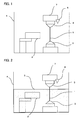
- FIG. 1 is a schematic diagram showing the configuration of a general wire electric discharge machine.
- Working fluid is not stored in a work tank 4.
- the wire electric discharge machine applies a voltage between a wire electrode 1 and a workpiece 2 and performs machining of the workpiece 2 while spraying the working fluid between the wire electrode 1 and the workpiece 2 from working fluid spray nozzles 3 respectively arranged in upper and lower parts.
- the entire wire electric discharge machine is arranged in the work tank 4 to be capable of collecting the working fluid used for the machining and machining sludge generated during the machining.
- wire electric discharge machining there are a method of machining a workpiece in a state in which working fluid is stored in a work tank and a wire electrode and the workpiece are submerged in the working fluid, which is called submerged machining, and a method of machining a workpiece only by spraying working fluid without submergence a wire electrode and the workpiece in the working fluid, which is called flushing machining.
- a normal wire electric discharge machine can operate in both the machining methods.
- the submerged machining is performed, at a point of machining start, after preparing for machining to, for example, place a workpiece and thread a wire electrode, an operator confirms that the wire electrode 1 and the workpiece 2 are in a completely submerged state in working fluid 5 as shown in FIG. 3 . Then, the operator turns on a machining power supply for applying a voltage between the wire electrode 1 and the workpiece 2 and sprays the working fluid 5 between the wire electrode 1 and the workpiece 2 to start machining.
- the conventional wire electric discharge machine can perform both of the submerged machining and the flushing machining as explained above, it is possible to start machining even if the wire electrode and the workpiece are not in a submerged state in the submerged machining. Therefore, if the machining is started when the working fluid is not stored at all as shown in FIG. 1 or when the fluid level of the working fluid is lower than predetermined height as shown in FIG. 2 , an electric shock due to contact with the wire electrode 1 and machining parts of the workpiece 2 and scattering of working fluid to the air are likely to occur.
- the technique disclosed in Japanese Patent Application Laid-Open No. 5-345230 is a technique for adjusting a supply amount of the working fluid to be stored in the work tank and controlling the supply amount to an appropriate amount of the working fluid.
- electric discharge machining is not prohibited even when the supply amount is not the appropriate amount of the working fluid, an electric shock due to contact with the wire electrode 1 and machining parts of the workpiece 2 and scattering of working fluid to the air are still likely to occur.
- the technique disclosed in Japanese Patent Application Laid-Open No. 59-232743 is a technique for detecting an abnormality during the machining by the electric discharge machine and eliminating the abnormality. Therefore, depending on the length of a time lag from occurrence to detection of an abnormality, an abnormal state such as fire is likely to occur.
- a wire electric discharge machine includes a work tank and a wire electrode arranged in the work tank.
- the wire electric discharge machine applies a voltage between a workpiece placed in the work tank and the wire electrode and performs machining of the workpiece while spraying working fluid between the wire electrode and the workpiece.
- the wire electric discharge machine further includes: a fluid level detecting unit configured to detect a fluid level of the working fluid in the work tank; a machining type discriminating unit configured to discriminate whether a type of the machining is submerged machining for performing the machining in a state in which the wire electrode and the workpiece are submerged in the working fluid or flushing machining for performing the machining in a state in which the wire electrode and the workpiece are not submerged in the working fluid; and a machining power application prohibiting unit configured to prohibit a machining power from being applied if a discrimination result by the machining type discriminating unit indicates that the machining type is the submerged machining and a detection result by the fluid level detecting unit indicates that the fluid level is lower than a predetermined position.
- the wire electric discharge machine in case where the type of the machining is the submerged machining, if it is detected by the fluid level detecting unit that the working fluid does not reach a predetermined fluid level and the working fluid is not in the submerged state, it is possible to prevent, by prohibiting a machining power from being applied, an electric shock due to contact with the wire electrode and machining parts of the workpiece and scattering of working fluid to the air, thereby improving safety.
- the wire electric discharge machine can further include a working fluid spray prohibiting unit configured to prohibit the working fluid from being sprayed between the wire electrode and the workpiece if the discrimination result by the machining type discriminating unit indicates that the machining type is the submerged machining and the detection result by the fluid level detecting unit indicates that the fluid level is lower than the predetermined position.
- the wire electric discharge machine can further include: a machining power application prohibiting unit configured to instruct application of a machining power for applying a voltage between the wire electrode and the workpiece; and a warning displaying unit configured to display a warning when an instruction of application of machining power is issued by the machining power application prohibiting unit if the discrimination result by the machining type discriminating unit indicates that the machining type is the submerged machining and the detection result by the fluid level detecting unit indicates that the fluid level is lower than the predetermined position.
- a machining power application prohibiting unit configured to instruct application of a machining power for applying a voltage between the wire electrode and the workpiece
- a warning displaying unit configured to display a warning when an instruction of application of machining power is issued by the machining power application prohibiting unit if the discrimination result by the machining type discriminating unit indicates that the machining type is the submerged machining and the detection result by the fluid level detecting unit indicates that the fluid level is lower than the predetermined position.
- the detection result by the fluid level detecting unit indicates that the fluid level is lower than the predetermined position so that it is inappropriate to perform submerged machining, it is possible to display a warning by the warning displaying unit and inform an operator that it is inappropriate to perform submerged machining when the instruction of application of machining power is issued by the machining power application prohibiting unit.
- the wire electric discharge machine can further include: a working fluid spray instructing unit configured to instruct spraying of the working fluid between the wire electrode and the workpiece; and a warning displaying unit configured to display a warning when a working fluid spray instruction is issued by the working fluid spray instructing unit if the discrimination result by the machining type discriminating unit indicates that the machining type is the submerged machining and the detection result by the fluid level detecting unit indicates that the fluid level is lower than the predetermined position.
- a working fluid spray instructing unit configured to instruct spraying of the working fluid between the wire electrode and the workpiece
- a warning displaying unit configured to display a warning when a working fluid spray instruction is issued by the working fluid spray instructing unit if the discrimination result by the machining type discriminating unit indicates that the machining type is the submerged machining and the detection result by the fluid level detecting unit indicates that the fluid level is lower than the predetermined position.
- the detection result by the fluid level detecting unit indicates that the fluid level is lower than the predetermined position so that it is inappropriate to perform submerged machining
- the wire electric discharge machine can further include: a machining power application prohibiting unit configured to instruct application of machining power for applying a voltage between the wire electrode and the workpiece; and a working fluid supplying unit configured to supply the working fluid to increase the working fluid in the work tank to a predetermined fluid level when an instruction of application of machining power is issued by the machining power application prohibiting unit if the discrimination result by the machining type discriminating unit indicates that the machining type is the submerged machining and the detection result by the fluid level detecting unit indicates that the fluid level is lower than the predetermined position.
- the working fluid is supplied to increase the working fluid to the predetermined fluid level by the working fluid supplying unit when the instruction of application of machining power is issued by the machining power application prohibiting unit. Consequently, even if the operator does not supply the working fluid, the working fluid is automatically supplied, bringing a state that allows discharge machining to be carried out in an appropriate manner.
- the wire electric discharge machine can further include: a working fluid spray instructing unit configured to instruct spraying of the working fluid between the wire electrode and the workpiece; and a working fluid supplying unit configured to supply the working fluid to increase the working fluid in the work tank to a predetermined fluid level when a working fluid spray instruction is issued by the working fluid spray instructing unit if the discrimination result by the machining type discriminating unit indicates that the machining type is the submerged machining and the detection result by the fluid level detecting unit indicates that the fluid level is lower than the predetermined position.
- a working fluid spray instructing unit configured to instruct spraying of the working fluid between the wire electrode and the workpiece
- a working fluid supplying unit configured to supply the working fluid to increase the working fluid in the work tank to a predetermined fluid level when a working fluid spray instruction is issued by the working fluid spray instructing unit if the discrimination result by the machining type discriminating unit indicates that the machining type is the submerged machining and the detection result by the fluid level detecting unit indicates that the fluid level is lower than the pre
- the working fluid is supplied to increase the working fluid to the predetermined fluid level by the working fluid supplying unit when instruction of spraying of the working fluid is issued by the working fluid spray instructing unit. Consequently, even if the operator does not supply the working fluid, the working fluid is automatically supplied, bringing a state that allows discharge machining to be carried out in an appropriate manner.
- a wire electric discharge machine that can detect that working fluid stored in a work tank is at predetermined height and attain improvement of safety and prevention of scattering of the working fluid.
- machining by a wire electric discharge machine there are a method of machining a workpiece 2 in a state in which a wire electrode 1 and a workpiece 2 are submerged in a working fluid 5 (submerged machining) and another method of machining a workpiece 2 only by spraying working fluid 5 in a state in which a wire electrode 1 and a workpiece 2 are not submerged in a working fluid 5 (flushing machining).
- An operator may set any one of those two machining methods that is to be carried out by means of a switch or the like.
- the wire electric discharge machine detects using a fluid level sensor 6 whether a fluid level of the working fluid 5 reaches a predetermined position. If a detection result of the fluid level sensor 6 indicates that the fluid level of the working fluid 5 does not reach the predetermined position, the wire electric discharge machine prohibits a machining power from applied for applying a voltage between the wire electrode 1 and the workpiece 2. In addition to prohibiting a machining power from being applied, it is also possible to prohibit the working fluid 5 from being sprayed between the wire electrode 1 and the workpiece 2.
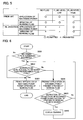
- FIG. 4 is a flowchart for explaining state discrimination processing in a work tank of a wire electric discharge machine according to a first embodiment of the present invention. The flowchart is explained below step by step.
- FIG. 5 is a table showing a state of permission or prohibition of operations according to a difference in level height of the working fluid 5, comparing the wire electric discharge machine according to the first embodiment of the present invention with conventional wire electric discharge machines.
- FIG. 6 is a flowchart for explaining state discrimination processing in a work tank of a wire electric discharge machine according to a second embodiment of the present invention.
- a function for displaying a warning when an instruction of application of machining power or an instruction of spraying of the working fluid 5 is issued if a fluid level of the working fluid 5 is lower than a predetermined fluid level is added to the state discrimination processing in the work tank according to the first embodiment.
- the flowchart is explained step by step.
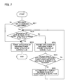
- FIG. 7 is a flowchart for explaining state discrimination processing in a work tank of a wire electric discharge machine according to a third embodiment of the present invention.
- a function for automatically supplying working fluid 5 when an instruction of application of machining power or an instruction of spraying of the working fluid 5 is issued if a fluid level of the working fluid 5 is lower than a predetermined fluid level is added to the state discrimination processing in the work tank according to the first embodiment.
- the flowchart is explained step by step.
- an operator operates switching of machining method to the submerged machining or the flushing machining in the wire electric discharge machine.
- a method of switching the machining method is not limited to this method.
- Other methods such as a method of instructing the machining method in a machining program may be used, for example.
- a sensor fixed to a guide block 7 on the upper side is used as the fluid level sensor 6.
- sensors of other types such as a float switch can also be used as the fluid level sensor 6.
- warning is displayed when an instruction of application of machining power or an instruction of spraying of the working fluid 5 is issued if the fluid level of the working fluid 5 is lower than the predetermined fluid level.
- the working fluid 5 is automatically supplied when an instruction of application of machining power or an instruction of spraying of the working fluid 5 is issued if the fluid level of the working fluid 5 is lower than the predetermined fluid level.
- the wire electric discharge machine may be configured to display the warning simultaneously with automatically supplying the working fluid 5.
Landscapes
- Engineering & Computer Science (AREA)
- Mechanical Engineering (AREA)
- Chemical & Material Sciences (AREA)
- Chemical Kinetics & Catalysis (AREA)
- Electrochemistry (AREA)
- Electrical Discharge Machining, Electrochemical Machining, And Combined Machining (AREA)
Abstract
Description
- The present invention relates to a wire electric discharge machine having a function for discriminating a state in a work tank.
-
FIG. 1 is a schematic diagram showing the configuration of a general wire electric discharge machine. Working fluid is not stored in awork tank 4. The wire electric discharge machine applies a voltage between awire electrode 1 and aworkpiece 2 and performs machining of theworkpiece 2 while spraying the working fluid between thewire electrode 1 and theworkpiece 2 from workingfluid spray nozzles 3 respectively arranged in upper and lower parts. As shown inFIG. 1 , the entire wire electric discharge machine is arranged in thework tank 4 to be capable of collecting the working fluid used for the machining and machining sludge generated during the machining. - In wire electric discharge machining, there are a method of machining a workpiece in a state in which working fluid is stored in a work tank and a wire electrode and the workpiece are submerged in the working fluid, which is called submerged machining, and a method of machining a workpiece only by spraying working fluid without submergence a wire electrode and the workpiece in the working fluid, which is called flushing machining. A normal wire electric discharge machine can operate in both the machining methods.
- When the submerged machining is performed, at a point of machining start, after preparing for machining to, for example, place a workpiece and thread a wire electrode, an operator confirms that the
wire electrode 1 and theworkpiece 2 are in a completely submerged state in workingfluid 5 as shown inFIG. 3 . Then, the operator turns on a machining power supply for applying a voltage between thewire electrode 1 and theworkpiece 2 and sprays the workingfluid 5 between thewire electrode 1 and theworkpiece 2 to start machining. - The wire electric discharge machine employing the submerged machining is disclosed in the following patent documents.
- (1) Japanese Patent Application Laid-Open No.
5-345230 - (2) Japanese Patent Application Laid-Open No.
59-232743 - Since the conventional wire electric discharge machine can perform both of the submerged machining and the flushing machining as explained above, it is possible to start machining even if the wire electrode and the workpiece are not in a submerged state in the submerged machining. Therefore, if the machining is started when the working fluid is not stored at all as shown in
FIG. 1 or when the fluid level of the working fluid is lower than predetermined height as shown inFIG. 2 , an electric shock due to contact with thewire electrode 1 and machining parts of theworkpiece 2 and scattering of working fluid to the air are likely to occur. - The technique disclosed in Japanese Patent Application Laid-Open No.
5-345230 wire electrode 1 and machining parts of theworkpiece 2 and scattering of working fluid to the air are still likely to occur. - Further, the technique disclosed in Japanese Patent Application Laid-Open No.
59-232743 - Therefore, it is an object of the present invention to provide a wire electric discharge machine that can detect that working fluid stored in a work tank is at predetermined height and attain improvement of safety and prevention of scattering of the working fluid.
- A wire electric discharge machine according to the present invention includes a work tank and a wire electrode arranged in the work tank. The wire electric discharge machine applies a voltage between a workpiece placed in the work tank and the wire electrode and performs machining of the workpiece while spraying working fluid between the wire electrode and the workpiece. The wire electric discharge machine further includes: a fluid level detecting unit configured to detect a fluid level of the working fluid in the work tank; a machining type discriminating unit configured to discriminate whether a type of the machining is submerged machining for performing the machining in a state in which the wire electrode and the workpiece are submerged in the working fluid or flushing machining for performing the machining in a state in which the wire electrode and the workpiece are not submerged in the working fluid; and a machining power application prohibiting unit configured to prohibit a machining power from being applied if a discrimination result by the machining type discriminating unit indicates that the machining type is the submerged machining and a detection result by the fluid level detecting unit indicates that the fluid level is lower than a predetermined position.
- In the wire electric discharge machine according to the present invention, in case where the type of the machining is the submerged machining, if it is detected by the fluid level detecting unit that the working fluid does not reach a predetermined fluid level and the working fluid is not in the submerged state, it is possible to prevent, by prohibiting a machining power from being applied, an electric shock due to contact with the wire electrode and machining parts of the workpiece and scattering of working fluid to the air, thereby improving safety.
- The wire electric discharge machine can further include a working fluid spray prohibiting unit configured to prohibit the working fluid from being sprayed between the wire electrode and the workpiece if the discrimination result by the machining type discriminating unit indicates that the machining type is the submerged machining and the detection result by the fluid level detecting unit indicates that the fluid level is lower than the predetermined position.
- In this embodiment, in addition to prohibiting a machining power from being applied, it is possible to further prevent, by prohibiting the working fluid from being sprayed between the wire electrode and the workpiece, the working fluid from scattering to the air, thereby further improving safety.
- The wire electric discharge machine can further include: a machining power application prohibiting unit configured to instruct application of a machining power for applying a voltage between the wire electrode and the workpiece; and a warning displaying unit configured to display a warning when an instruction of application of machining power is issued by the machining power application prohibiting unit if the discrimination result by the machining type discriminating unit indicates that the machining type is the submerged machining and the detection result by the fluid level detecting unit indicates that the fluid level is lower than the predetermined position.
- In this embodiment, if the detection result by the fluid level detecting unit indicates that the fluid level is lower than the predetermined position so that it is inappropriate to perform submerged machining, it is possible to display a warning by the warning displaying unit and inform an operator that it is inappropriate to perform submerged machining when the instruction of application of machining power is issued by the machining power application prohibiting unit.
- The wire electric discharge machine can further include: a working fluid spray instructing unit configured to instruct spraying of the working fluid between the wire electrode and the workpiece; and a warning displaying unit configured to display a warning when a working fluid spray instruction is issued by the working fluid spray instructing unit if the discrimination result by the machining type discriminating unit indicates that the machining type is the submerged machining and the detection result by the fluid level detecting unit indicates that the fluid level is lower than the predetermined position.
- In this embodiment, if the detection result by the fluid level detecting unit indicates that the fluid level is lower than the predetermined position so that it is inappropriate to perform submerged machining, it is possible to display a warning by the warning displaying unit and inform the operator that it is inappropriate to perform submerged machining when instruction of spraying of the working fluid is issued by the working fluid spray instructing unit.
- The wire electric discharge machine can further include: a machining power application prohibiting unit configured to instruct application of machining power for applying a voltage between the wire electrode and the workpiece; and a working fluid supplying unit configured to supply the working fluid to increase the working fluid in the work tank to a predetermined fluid level when an instruction of application of machining power is issued by the machining power application prohibiting unit if the discrimination result by the machining type discriminating unit indicates that the machining type is the submerged machining and the detection result by the fluid level detecting unit indicates that the fluid level is lower than the predetermined position.
- In this embodiment, if the detection result by the fluid level detecting unit indicates that the fluid level is lower than the predetermined position so that it is inappropriate to perform submerged machining, the working fluid is supplied to increase the working fluid to the predetermined fluid level by the working fluid supplying unit when the instruction of application of machining power is issued by the machining power application prohibiting unit. Consequently, even if the operator does not supply the working fluid, the working fluid is automatically supplied, bringing a state that allows discharge machining to be carried out in an appropriate manner.
- The wire electric discharge machine can further include: a working fluid spray instructing unit configured to instruct spraying of the working fluid between the wire electrode and the workpiece; and a working fluid supplying unit configured to supply the working fluid to increase the working fluid in the work tank to a predetermined fluid level when a working fluid spray instruction is issued by the working fluid spray instructing unit if the discrimination result by the machining type discriminating unit indicates that the machining type is the submerged machining and the detection result by the fluid level detecting unit indicates that the fluid level is lower than the predetermined position.
- In this embodiment, if the detection result by the fluid level detecting unit indicates that the fluid level is lower than the predetermined position so that it is inappropriate to perform submerged machining, the working fluid is supplied to increase the working fluid to the predetermined fluid level by the working fluid supplying unit when instruction of spraying of the working fluid is issued by the working fluid spray instructing unit. Consequently, even if the operator does not supply the working fluid, the working fluid is automatically supplied, bringing a state that allows discharge machining to be carried out in an appropriate manner.
- According to the present invention, it is possible to provide a wire electric discharge machine that can detect that working fluid stored in a work tank is at predetermined height and attain improvement of safety and prevention of scattering of the working fluid.
- The object and the characteristics explained above and other objects and characteristics of the present invention will be made apparent from the following explanation of embodiments with reference to the accompanying drawings, wherein:
-
FIG. 1 is a schematic diagram showing the configuration of a wire electric discharge machine and shows a state in which no working fluid is stored in a work tank; -
FIG. 2 is a schematic diagram showing the configuration of the wire electric discharge machine and shows a state in which a fluid level of working fluid in the work tank is lower than predetermine height; -
FIG. 3 is a schematic diagram showing the configuration of the wire electric discharge machine and shows a state in which the fluid level of the working fluid in the work tank has the predetermined height; -
FIG. 4 is a flowchart for explaining state discrimination processing in a work tank of a wire electric discharge machine according to a first embodiment of the present invention; -
FIG. 5 is a table showing a state of permission or prohibition of operations according to a difference in level height of working fluid while comparing the present invention and the related art; -
FIG. 6 is a flowchart for explaining state discrimination processing in a work tank of a wire electric discharge machine according to a second embodiment of the present invention; and -
FIG. 7 is a flowchart for explaining state discrimination processing in a work tank of a wire electric discharge machine according to a third embodiment of the present invention. - In machining by a wire electric discharge machine, as explained above, there are a method of machining a
workpiece 2 in a state in which awire electrode 1 and aworkpiece 2 are submerged in a working fluid 5 (submerged machining) and another method of machining aworkpiece 2 only by spraying workingfluid 5 in a state in which awire electrode 1 and aworkpiece 2 are not submerged in a working fluid 5 (flushing machining). An operator may set any one of those two machining methods that is to be carried out by means of a switch or the like. - When the machining is set to the submerged machining, the wire electric discharge machine detects using a
fluid level sensor 6 whether a fluid level of the workingfluid 5 reaches a predetermined position. If a detection result of thefluid level sensor 6 indicates that the fluid level of theworking fluid 5 does not reach the predetermined position, the wire electric discharge machine prohibits a machining power from applied for applying a voltage between thewire electrode 1 and theworkpiece 2. In addition to prohibiting a machining power from being applied, it is also possible to prohibit the workingfluid 5 from being sprayed between thewire electrode 1 and theworkpiece 2. -
FIG. 4 is a flowchart for explaining state discrimination processing in a work tank of a wire electric discharge machine according to a first embodiment of the present invention. The flowchart is explained below step by step. - (Step SA1) It is determined whether a machining type of machining by a wire electric discharge machine is the submerged machining or not. If the machining type is the submerged machining (YES), the processing proceeds to step SA2. If the machining type is a machining other than the submerged machining, such as the flushing machining (NO), the processing proceeds to step SA3.
- (Step SA2) A fluid level of the working
fluid 5 is detected by thefluid level sensor 6 and it is determined whether the fluid level of the workingfluid 5 is equal to or higher than a predetermined fluid level. If the fluid level is equal to or higher than the predetermined fluid level (YES), the processing proceeds to step SA3. If the fluid level is lower than the predetermined fluid level (NO), the processing proceeds to step SA4. - (Step SA3) Application of power is permitted and spraying of the working
fluid 5 is permitted, and the processing is ended. - (Step SA4) Application of power is prohibited and spraying of the working
fluid 5 is prohibited, and the processing returns to step SA2. -
FIG. 5 is a table showing a state of permission or prohibition of operations according to a difference in level height of the workingfluid 5, comparing the wire electric discharge machine according to the first embodiment of the present invention with conventional wire electric discharge machines. - As apparent from the table of
FIG. 5 , in the case of the prior art, application of machining power and spraying of working fluid are permitted even when workingfluid 5 is not stored, even when the level of the workingfluid 5 is lower than the predetermine level height (at a low fluid level), or when the workingfluid 5 reaches the predetermined level height (at a high fluid level). In the case of the embodiment, on the other hand, application of machining power and spraying of the working fluid are prohibited when the workingfluid 5 is not stored or when the level of the workingfluid 5 is lower than the predetermined fluid height (at a low fluid level). Application of machining power and spraying of the working fluid are permitted only when the workingfluid 5 reaches the predetermined level height (at a high fluid level). Therefore, in this embodiment, it is possible to attain improvement of safety and prevent the workingfluid 5 from scattering. -
FIG. 6 is a flowchart for explaining state discrimination processing in a work tank of a wire electric discharge machine according to a second embodiment of the present invention. In the state discrimination processing in the work tank according to this embodiment, a function for displaying a warning when an instruction of application of machining power or an instruction of spraying of the workingfluid 5 is issued if a fluid level of the workingfluid 5 is lower than a predetermined fluid level is added to the state discrimination processing in the work tank according to the first embodiment. In the following explanation, the flowchart is explained step by step. - (Step SB1) It is determined whether a machining type of machining by a wire electric discharge machine is the submerged machining or not. If the machining type is the submerged machining (YES), the processing proceeds to step SB2. If the machining type is a machining other than the submerged machining, such as the flushing machining (NO), the processing proceeds to step SB3.
- (Step SB2) A fluid level of the working
fluid 5 is detected by thefluid level sensor 6 and it is determined whether the fluid level of the workingfluid 5 is equal to or higher than a predetermined fluid level. If the fluid level of the workingfluid 5 is equal to or higher than the predetermined fluid level (YES), the processing proceeds to step SB3. If the fluid level of the workingfluid 5 is lower than the predetermined fluid level (NO), the processing proceeds to step SB4. - (Step SB3) Application of power is permitted and spraying of the working
fluid 5 is permitted, and the processing is ended. - (Step SB4) Application of power is prohibited and spraying of the working
fluid 5 is prohibited. - (Step SB5) It is determined whether an instruction of application of machining power or an instruction of spraying of the working
fluid 5 is issued or not. If the instruction is issued (YES), the processing proceeds to step SB6. On the other hand, if the instruction is not issued (NO), the processing returns to step SB2. - (Step SB6) Warning is displayed and the processing returns to step SB2.
-
FIG. 7 is a flowchart for explaining state discrimination processing in a work tank of a wire electric discharge machine according to a third embodiment of the present invention. In the state discrimination processing in the work tank according to this embodiment, a function for automatically supplying workingfluid 5 when an instruction of application of machining power or an instruction of spraying of the workingfluid 5 is issued if a fluid level of the workingfluid 5 is lower than a predetermined fluid level is added to the state discrimination processing in the work tank according to the first embodiment. In the following explanation, the flowchart is explained step by step. - (Step SC1) It is determined whether a machining type of machining by a wire electric discharge machine is the submerged machining or not. If the machining type is the submerged machining (YES), the processing proceeds to step SC2. If the machining type is a machining other than the submerged machining, such as the flushing machining (NO), the processing proceeds to step SC3.
- (Step SC2) A fluid level of the working
fluid 5 is detected by thefluid level sensor 6 and it is determined whether the fluid level of the workingfluid 5 is equal to or higher than a predetermined fluid level. If the fluid level is equal to or higher than the predetermined fluid level (YES), the processing proceeds to step SC3. If the fluid level is lower than the predetermined fluid level (NO), the processing proceeds to step SC4. - (Step SC3) Application of power is permitted and spraying of the working
fluid 5 is permitted, and the processing is ended. - (Step SC4) Application of power is prohibited and spraying of the working
fluid 5 is prohibited. - (Step SC5) It is determined whether an instruction of application of machining power or an instruction of spraying of the working
fluid 5 is issued or not. If the instruction is issued (YES), the processing proceeds to step SC6. On the other hand, if the instruction is not issued (NO), the processing returns to step SC2. - (Step SC6) The working
fluid 5 is automatically supplied for submerged in the work tank, and the processing returns to step SC2. - In the embodiments, an operator operates switching of machining method to the submerged machining or the flushing machining in the wire electric discharge machine. However, a method of switching the machining method is not limited to this method. Other methods such as a method of instructing the machining method in a machining program may be used, for example.
- In the embodiments, a sensor fixed to a
guide block 7 on the upper side is used as thefluid level sensor 6. However, sensors of other types such as a float switch can also be used as thefluid level sensor 6. - Further, in the second embodiment (the flowchart of
FIG. 6 ), warning is displayed when an instruction of application of machining power or an instruction of spraying of the workingfluid 5 is issued if the fluid level of the workingfluid 5 is lower than the predetermined fluid level. In the third embodiment (the flowchart ofFIG. 7 ), the workingfluid 5 is automatically supplied when an instruction of application of machining power or an instruction of spraying of the workingfluid 5 is issued if the fluid level of the workingfluid 5 is lower than the predetermined fluid level. However, the wire electric discharge machine may be configured to display the warning simultaneously with automatically supplying the workingfluid 5.
Claims (6)
- A wire electric discharge machine comprising:a work tank; anda wire electrode arranged in the work tank,the wire electric discharge machine applying a voltage between a workpiece placed in the work tank and the wire electrode and performing machining of the workpiece while spraying working fluid between the wire electrode and the workpiece,the wire electric discharge machine further comprising:a fluid level detecting unit configured to detect a fluid level of the working fluid in the work tank;a machining type discriminating unit configured to discriminate whether a type of the machining is submerged machining for performing the machining in a state in which the wire electrode and the workpiece are submerged in the working fluid or flushing machining for performing the machining in a state in which the wire electrode and the workpiece are not submerged in the working fluid; anda machining power application prohibiting unit configured to prohibit a machining power from being applied if a discrimination result by the machining type discriminating unit indicates that the machining type is the submerged machining and a detection result by the fluid level detecting unit indicates that the fluid level is lower than a predetermined position.
- The wire electric discharge machine according to claim 1, further comprising a working fluid spray prohibiting unit configured to prohibit the working fluid from being sprayed between the wire electrode and the workpiece if the discrimination result by the machining type discriminating unit indicates that the machining type is the submerged machining and the detection result by the fluid level detecting unit indicates that the fluid level is lower than the predetermined position.
- The wire electric discharge machine according to claim 1 or 2, further comprising:a machining power application prohibiting unit configured to instruct application of machining power for applying a voltage between the wire electrode and the workpiece; anda warning displaying unit configured to display a warning when an instruction of application of machining power is issued by the machining power application prohibiting unit if the discrimination result by the machining type discriminating unit indicates that the machining type is the submerged machining and the detection result by the fluid level detecting unit indicates that the fluid level is lower than the predetermined position.
- The wire electric discharge machine according to claim 1 or 2, further comprising:a working fluid spray instructing unit configured to instruct spraying of the working fluid between the wire electrode and the workpiece; anda warning displaying unit configured to display a warning when a working fluid spray instruction is issued by the working fluid spray instructing unit if the discrimination result by the machining type discriminating unit indicates that the machining type is the submerged machining and the detection result by the fluid level detecting unit indicates that the fluid level is lower than the predetermined position.
- The wire electric discharge machine according to claim 1 or 2, further comprising:a machining power application prohibiting unit configured to instruct application of machining power for applying a voltage between the wire electrode and the workpiece; anda working fluid supplying unit configured to supply the working fluid to increase the working fluid in the work tank to a predetermined fluid level when an instruction of application of machining power is issued by the machining power application prohibiting unit if the discrimination result by the machining type discriminating unit indicates that the machining type is the submerged machining and the detection result by the fluid level detecting unit indicates that the fluid level is lower than the predetermined position.
- The wire electric discharge machine according to claim 1 or 2, further comprising:a working fluid spray instructing unit configured to instruct spraying of the working fluid between the wire electrode and the workpiece; anda working fluid supplying unit configured to supply the working fluid to increase the working fluid in the work tank to a predetermined fluid level when a working fluid spray instruction is issued by the working fluid spray instructing unit if the discrimination result by the machining type discriminating unit indicates that the machining type is the submerged machining and the detection result by the fluid level detecting unit indicates that the fluid level is lower than the predetermined position.
Applications Claiming Priority (1)
| Application Number | Priority Date | Filing Date | Title |
|---|---|---|---|
| JP2013057317A JP5661840B2 (en) | 2013-03-19 | 2013-03-19 | Wire electric discharge machine having a function of discriminating the state in a processing tank |
Publications (2)
| Publication Number | Publication Date |
|---|---|
| EP2781289A2 true EP2781289A2 (en) | 2014-09-24 |
| EP2781289A3 EP2781289A3 (en) | 2014-12-10 |
Family
ID=50343634
Family Applications (1)
| Application Number | Title | Priority Date | Filing Date |
|---|---|---|---|
| EP14160487.6A Ceased EP2781289A3 (en) | 2013-03-19 | 2014-03-18 | Wire electric discharge machine having function for discriminating state in work tank |
Country Status (4)
| Country | Link |
|---|---|
| US (1) | US20140284311A1 (en) |
| EP (1) | EP2781289A3 (en) |
| JP (1) | JP5661840B2 (en) |
| CN (1) | CN104057166A (en) |
Families Citing this family (6)
| Publication number | Priority date | Publication date | Assignee | Title |
|---|---|---|---|---|
| JP6219785B2 (en) * | 2014-06-23 | 2017-10-25 | ファナック株式会社 | Wire electric discharge machine equipped with disconnection repair means |
| JP6567853B2 (en) | 2015-03-30 | 2019-08-28 | ファナック株式会社 | Electric discharge machine to change axis feed characteristics |
| JP2017121679A (en) * | 2016-01-06 | 2017-07-13 | ファナック株式会社 | Wire electric discharge machine |
| JP6321703B2 (en) * | 2016-03-04 | 2018-05-09 | ファナック株式会社 | Wire electrical discharge machine inspection system |
| JP6360212B1 (en) * | 2017-01-31 | 2018-07-18 | ファナック株式会社 | Wire electric discharge machine |
| JP6647468B1 (en) * | 2019-04-05 | 2020-02-14 | 三菱電機株式会社 | Wire electric discharge machine |
Citations (2)
| Publication number | Priority date | Publication date | Assignee | Title |
|---|---|---|---|---|
| JPS59232743A (en) | 1983-06-17 | 1984-12-27 | Inoue Japax Res Inc | Automatic fire-extinguishing device for machine tool |
| JPH05345230A (en) | 1992-04-15 | 1993-12-27 | Mitsubishi Electric Corp | Electric discharge machine |
Family Cites Families (11)
| Publication number | Priority date | Publication date | Assignee | Title |
|---|---|---|---|---|
| JPH04300123A (en) * | 1990-07-05 | 1992-10-23 | Mitsubishi Electric Corp | Wire cut electric discharge machining device |
| JP3335711B2 (en) * | 1993-05-18 | 2002-10-21 | 株式会社ソディック | Wire cut electric discharge machine |
| JP3519150B2 (en) * | 1994-12-22 | 2004-04-12 | 株式会社ソディック | Circuit device for electric discharge machining and electric discharge machine |
| JP4004666B2 (en) * | 1998-10-12 | 2007-11-07 | 株式会社ソディック | Wire cut electric discharge machine |
| CN1121295C (en) * | 1999-11-17 | 2003-09-17 | 沙迪克株式会社 | Liquid feeder for electrodischarge machining |
| JP4678703B2 (en) * | 2001-03-26 | 2011-04-27 | 株式会社ソディック | Wire electrical discharge machining method |
| JP3779289B2 (en) * | 2003-07-31 | 2006-05-24 | ファナック株式会社 | Processing fluid processing equipment for electrical discharge machining |
| JP4550615B2 (en) * | 2005-02-22 | 2010-09-22 | 株式会社ソディック | Automatic wire electrode connection method |
| JP4347251B2 (en) * | 2005-04-01 | 2009-10-21 | ファナック株式会社 | Machining fluid level detector for wire-cut electrical discharge machine |
| JP4422180B2 (en) * | 2007-12-13 | 2010-02-24 | ファナック株式会社 | Wire cut electrical discharge machine with water level abnormality detection function and method for identifying cause of water level abnormality alarm |
| JP5226839B2 (en) * | 2011-08-17 | 2013-07-03 | ファナック株式会社 | Wire electrical discharge machine with positioning accuracy correction function |
-
2013
- 2013-03-19 JP JP2013057317A patent/JP5661840B2/en not_active Expired - Fee Related
-
2014
- 2014-03-18 US US14/218,867 patent/US20140284311A1/en not_active Abandoned
- 2014-03-18 CN CN201410100460.1A patent/CN104057166A/en active Pending
- 2014-03-18 EP EP14160487.6A patent/EP2781289A3/en not_active Ceased
Patent Citations (2)
| Publication number | Priority date | Publication date | Assignee | Title |
|---|---|---|---|---|
| JPS59232743A (en) | 1983-06-17 | 1984-12-27 | Inoue Japax Res Inc | Automatic fire-extinguishing device for machine tool |
| JPH05345230A (en) | 1992-04-15 | 1993-12-27 | Mitsubishi Electric Corp | Electric discharge machine |
Also Published As
| Publication number | Publication date |
|---|---|
| JP5661840B2 (en) | 2015-01-28 |
| EP2781289A3 (en) | 2014-12-10 |
| JP2014180734A (en) | 2014-09-29 |
| US20140284311A1 (en) | 2014-09-25 |
| CN104057166A (en) | 2014-09-24 |
Similar Documents
| Publication | Publication Date | Title |
|---|---|---|
| US20140284311A1 (en) | Wire electric discharge machine having function for discriminating state in work tank | |
| US9069347B2 (en) | Machine tool comprising a device for collision monitoring | |
| EP2926935B1 (en) | Wire electric discharge machine | |
| KR101462312B1 (en) | Tool monitoring system of machine tools and method thereof | |
| KR20040060741A (en) | A Tool Error Detecting Unit of CNC and Method Thereof | |
| CN106925886B (en) | The laser cutting method and laser cutting machine of beam are turned off at the end of cutting | |
| KR101626458B1 (en) | Apparatus for detecting malfunction of tool for machine tool | |
| CN106903385B (en) | Wire EDM | |
| JP2017080865A (en) | Monitoring device of machine tool | |
| JPWO2009128156A1 (en) | Collision detection device and collision detection method in processing machine | |
| US20160259320A1 (en) | Numerical controller capable of avoiding overheat of spindle | |
| JP6567853B2 (en) | Electric discharge machine to change axis feed characteristics | |
| EP3377263B1 (en) | Method and device for detecting an impending incomplete cut or an incomplete cut which has already occurred when thermally separating a workpiece | |
| KR101777476B1 (en) | Electric discharge machine | |
| JP5722290B2 (en) | Wire electric discharge machine with axis feed control method discrimination function | |
| KR20230073333A (en) | Wire electric discharge machine, and control method of wire electric discharge machine | |
| JP2006021322A (en) | Safety device for automatic machine system | |
| KR20150087651A (en) | Apparatus and method for detecting a workpiece | |
| JP4864960B2 (en) | Wire electrical discharge machine | |
| KR20100133048A (en) | Injection nozzle device that transmits alarm by judging whether there is a defect during operation of machine tool | |
| US9278400B2 (en) | Electric-discharge machining device | |
| WO2014087457A1 (en) | Electrical discharge machining device | |
| JP4390981B2 (en) | Machine tool operating area monitoring device | |
| JP6454313B2 (en) | Method and apparatus for drilling concrete structures | |
| KR101368012B1 (en) | Apparatus for detecting of abnormality of tool |
Legal Events
| Date | Code | Title | Description |
|---|---|---|---|
| PUAI | Public reference made under article 153(3) epc to a published international application that has entered the european phase |
Free format text: ORIGINAL CODE: 0009012 |
|
| 17P | Request for examination filed |
Effective date: 20140318 |
|
| AK | Designated contracting states |
Kind code of ref document: A2 Designated state(s): AL AT BE BG CH CY CZ DE DK EE ES FI FR GB GR HR HU IE IS IT LI LT LU LV MC MK MT NL NO PL PT RO RS SE SI SK SM TR |
|
| AX | Request for extension of the european patent |
Extension state: BA ME |
|
| PUAL | Search report despatched |
Free format text: ORIGINAL CODE: 0009013 |
|
| AK | Designated contracting states |
Kind code of ref document: A3 Designated state(s): AL AT BE BG CH CY CZ DE DK EE ES FI FR GB GR HR HU IE IS IT LI LT LU LV MC MK MT NL NO PL PT RO RS SE SI SK SM TR |
|
| AX | Request for extension of the european patent |
Extension state: BA ME |
|
| RIC1 | Information provided on ipc code assigned before grant |
Ipc: B23H 1/08 20060101ALI20141105BHEP Ipc: B23H 1/02 20060101AFI20141105BHEP Ipc: B23H 7/20 20060101ALN20141105BHEP Ipc: B23H 7/36 20060101ALI20141105BHEP Ipc: B23H 1/10 20060101ALI20141105BHEP Ipc: B23H 7/02 20060101ALN20141105BHEP |
|
| R17P | Request for examination filed (corrected) |
Effective date: 20150521 |
|
| RBV | Designated contracting states (corrected) |
Designated state(s): AL AT BE BG CH CY CZ DE DK EE ES FI FR GB GR HR HU IE IS IT LI LT LU LV MC MK MT NL NO PL PT RO RS SE SI SK SM TR |
|
| 17Q | First examination report despatched |
Effective date: 20161109 |
|
| 18R | Application refused |
Effective date: 20180406 |