EP2780699B1 - Verfahren zur rekonstruktion der geometrie einer oberfläche eines objekts durch echoloten, entsprechendes computerprogramm und vorrichtung zur ultraschallprüfung - Google Patents
Verfahren zur rekonstruktion der geometrie einer oberfläche eines objekts durch echoloten, entsprechendes computerprogramm und vorrichtung zur ultraschallprüfung Download PDFInfo
- Publication number
- EP2780699B1 EP2780699B1 EP12794408.0A EP12794408A EP2780699B1 EP 2780699 B1 EP2780699 B1 EP 2780699B1 EP 12794408 A EP12794408 A EP 12794408A EP 2780699 B1 EP2780699 B1 EP 2780699B1
- Authority
- EP
- European Patent Office
- Prior art keywords
- transducers
- transducer
- geometry
- reconstructing
- probe
- Prior art date
- Legal status (The legal status is an assumption and is not a legal conclusion. Google has not performed a legal analysis and makes no representation as to the accuracy of the status listed.)
- Active
Links
- 238000000034 method Methods 0.000 title claims description 63
- 238000004590 computer program Methods 0.000 title claims description 19
- 230000001934 delay Effects 0.000 claims description 84
- 239000000523 sample Substances 0.000 claims description 56
- 238000005259 measurement Methods 0.000 claims description 39
- 230000005540 biological transmission Effects 0.000 claims description 36
- 238000012545 processing Methods 0.000 claims description 24
- 238000002604 ultrasonography Methods 0.000 claims description 24
- 238000002592 echocardiography Methods 0.000 claims description 11
- 239000011159 matrix material Substances 0.000 claims description 8
- 238000012360 testing method Methods 0.000 claims description 8
- 238000004891 communication Methods 0.000 claims description 2
- 239000002131 composite material Substances 0.000 description 17
- 239000011324 bead Substances 0.000 description 13
- 230000007547 defect Effects 0.000 description 12
- 238000009659 non-destructive testing Methods 0.000 description 11
- 230000000295 complement effect Effects 0.000 description 10
- 230000008569 process Effects 0.000 description 9
- 238000001514 detection method Methods 0.000 description 7
- 238000004364 calculation method Methods 0.000 description 6
- 238000006073 displacement reaction Methods 0.000 description 5
- 238000007689 inspection Methods 0.000 description 5
- 238000005516 engineering process Methods 0.000 description 4
- 230000006870 function Effects 0.000 description 4
- 238000003384 imaging method Methods 0.000 description 4
- XLYOFNOQVPJJNP-UHFFFAOYSA-N water Substances O XLYOFNOQVPJJNP-UHFFFAOYSA-N 0.000 description 4
- 238000003491 array Methods 0.000 description 3
- 230000032798 delamination Effects 0.000 description 3
- 238000011156 evaluation Methods 0.000 description 3
- 239000000463 material Substances 0.000 description 3
- 239000002184 metal Substances 0.000 description 3
- 238000013508 migration Methods 0.000 description 3
- 230000005012 migration Effects 0.000 description 3
- 238000004441 surface measurement Methods 0.000 description 3
- 238000011282 treatment Methods 0.000 description 3
- 238000012512 characterization method Methods 0.000 description 2
- 230000001066 destructive effect Effects 0.000 description 2
- 239000007788 liquid Substances 0.000 description 2
- 238000012805 post-processing Methods 0.000 description 2
- 238000012552 review Methods 0.000 description 2
- 229920000049 Carbon (fiber) Polymers 0.000 description 1
- 229920000297 Rayon Polymers 0.000 description 1
- 230000003044 adaptive effect Effects 0.000 description 1
- 238000004458 analytical method Methods 0.000 description 1
- 230000008901 benefit Effects 0.000 description 1
- 229910052799 carbon Inorganic materials 0.000 description 1
- 239000004917 carbon fiber Substances 0.000 description 1
- 230000015556 catabolic process Effects 0.000 description 1
- 238000012937 correction Methods 0.000 description 1
- 230000001186 cumulative effect Effects 0.000 description 1
- 238000006731 degradation reaction Methods 0.000 description 1
- 238000010586 diagram Methods 0.000 description 1
- 239000004744 fabric Substances 0.000 description 1
- 238000009472 formulation Methods 0.000 description 1
- 238000007654 immersion Methods 0.000 description 1
- 230000004807 localization Effects 0.000 description 1
- VNWKTOKETHGBQD-UHFFFAOYSA-N methane Chemical compound C VNWKTOKETHGBQD-UHFFFAOYSA-N 0.000 description 1
- 239000000203 mixture Substances 0.000 description 1
- 238000012986 modification Methods 0.000 description 1
- 230000004048 modification Effects 0.000 description 1
- 230000001902 propagating effect Effects 0.000 description 1
- 239000002964 rayon Substances 0.000 description 1
- 238000011897 real-time detection Methods 0.000 description 1
- 239000011347 resin Substances 0.000 description 1
- 229920005989 resin Polymers 0.000 description 1
- 230000004044 response Effects 0.000 description 1
- 230000001360 synchronised effect Effects 0.000 description 1
- 230000009466 transformation Effects 0.000 description 1
- 238000012285 ultrasound imaging Methods 0.000 description 1
- 238000003466 welding Methods 0.000 description 1
Images


Classifications
-
- G—PHYSICS
- G01—MEASURING; TESTING
- G01B—MEASURING LENGTH, THICKNESS OR SIMILAR LINEAR DIMENSIONS; MEASURING ANGLES; MEASURING AREAS; MEASURING IRREGULARITIES OF SURFACES OR CONTOURS
- G01B17/00—Measuring arrangements characterised by the use of infrasonic, sonic or ultrasonic vibrations
- G01B17/06—Measuring arrangements characterised by the use of infrasonic, sonic or ultrasonic vibrations for measuring contours or curvatures
-
- A—HUMAN NECESSITIES
- A61—MEDICAL OR VETERINARY SCIENCE; HYGIENE
- A61B—DIAGNOSIS; SURGERY; IDENTIFICATION
- A61B8/00—Diagnosis using ultrasonic, sonic or infrasonic waves
- A61B8/52—Devices using data or image processing specially adapted for diagnosis using ultrasonic, sonic or infrasonic waves
- A61B8/5207—Devices using data or image processing specially adapted for diagnosis using ultrasonic, sonic or infrasonic waves involving processing of raw data to produce diagnostic data, e.g. for generating an image
-
- A—HUMAN NECESSITIES
- A61—MEDICAL OR VETERINARY SCIENCE; HYGIENE
- A61B—DIAGNOSIS; SURGERY; IDENTIFICATION
- A61B8/00—Diagnosis using ultrasonic, sonic or infrasonic waves
- A61B8/13—Tomography
- A61B8/14—Echo-tomography
- A61B8/145—Echo-tomography characterised by scanning multiple planes
-
- A—HUMAN NECESSITIES
- A61—MEDICAL OR VETERINARY SCIENCE; HYGIENE
- A61B—DIAGNOSIS; SURGERY; IDENTIFICATION
- A61B8/00—Diagnosis using ultrasonic, sonic or infrasonic waves
- A61B8/44—Constructional features of the ultrasonic, sonic or infrasonic diagnostic device
- A61B8/4444—Constructional features of the ultrasonic, sonic or infrasonic diagnostic device related to the probe
-
- A—HUMAN NECESSITIES
- A61—MEDICAL OR VETERINARY SCIENCE; HYGIENE
- A61B—DIAGNOSIS; SURGERY; IDENTIFICATION
- A61B8/00—Diagnosis using ultrasonic, sonic or infrasonic waves
- A61B8/54—Control of the diagnostic device
-
- G—PHYSICS
- G01—MEASURING; TESTING
- G01N—INVESTIGATING OR ANALYSING MATERIALS BY DETERMINING THEIR CHEMICAL OR PHYSICAL PROPERTIES
- G01N29/00—Investigating or analysing materials by the use of ultrasonic, sonic or infrasonic waves; Visualisation of the interior of objects by transmitting ultrasonic or sonic waves through the object
- G01N29/04—Analysing solids
- G01N29/06—Visualisation of the interior, e.g. acoustic microscopy
- G01N29/0654—Imaging
-
- G—PHYSICS
- G01—MEASURING; TESTING
- G01N—INVESTIGATING OR ANALYSING MATERIALS BY DETERMINING THEIR CHEMICAL OR PHYSICAL PROPERTIES
- G01N29/00—Investigating or analysing materials by the use of ultrasonic, sonic or infrasonic waves; Visualisation of the interior of objects by transmitting ultrasonic or sonic waves through the object
- G01N29/22—Details, e.g. general constructional or apparatus details
- G01N29/26—Arrangements for orientation or scanning by relative movement of the head and the sensor
- G01N29/262—Arrangements for orientation or scanning by relative movement of the head and the sensor by electronic orientation or focusing, e.g. with phased arrays
-
- G—PHYSICS
- G01—MEASURING; TESTING
- G01N—INVESTIGATING OR ANALYSING MATERIALS BY DETERMINING THEIR CHEMICAL OR PHYSICAL PROPERTIES
- G01N29/00—Investigating or analysing materials by the use of ultrasonic, sonic or infrasonic waves; Visualisation of the interior of objects by transmitting ultrasonic or sonic waves through the object
- G01N29/44—Processing the detected response signal, e.g. electronic circuits specially adapted therefor
-
- A—HUMAN NECESSITIES
- A61—MEDICAL OR VETERINARY SCIENCE; HYGIENE
- A61B—DIAGNOSIS; SURGERY; IDENTIFICATION
- A61B8/00—Diagnosis using ultrasonic, sonic or infrasonic waves
- A61B8/44—Constructional features of the ultrasonic, sonic or infrasonic diagnostic device
- A61B8/4483—Constructional features of the ultrasonic, sonic or infrasonic diagnostic device characterised by features of the ultrasound transducer
- A61B8/4494—Constructional features of the ultrasonic, sonic or infrasonic diagnostic device characterised by features of the ultrasound transducer characterised by the arrangement of the transducer elements
-
- G—PHYSICS
- G01—MEASURING; TESTING
- G01N—INVESTIGATING OR ANALYSING MATERIALS BY DETERMINING THEIR CHEMICAL OR PHYSICAL PROPERTIES
- G01N2291/00—Indexing codes associated with group G01N29/00
- G01N2291/01—Indexing codes associated with the measuring variable
- G01N2291/011—Velocity or travel time
-
- G—PHYSICS
- G01—MEASURING; TESTING
- G01N—INVESTIGATING OR ANALYSING MATERIALS BY DETERMINING THEIR CHEMICAL OR PHYSICAL PROPERTIES
- G01N2291/00—Indexing codes associated with group G01N29/00
- G01N2291/10—Number of transducers
- G01N2291/106—Number of transducers one or more transducer arrays
-
- G—PHYSICS
- G01—MEASURING; TESTING
- G01N—INVESTIGATING OR ANALYSING MATERIALS BY DETERMINING THEIR CHEMICAL OR PHYSICAL PROPERTIES
- G01N2291/00—Indexing codes associated with group G01N29/00
- G01N2291/26—Scanned objects
- G01N2291/263—Surfaces
Definitions
- the present invention relates to a method of reconstructing the geometry of a surface of an object by ultrasound sounding using an ultrasonic probe provided with a plurality of transducers. It also relates to a computer program and an ultrasound probe for implementing this method.
- the invention applies in particular to the field of non-destructive testing of mechanical parts having a complex shape, in particular during an immersion test, in which a mechanical part is immersed in a liquid to be probed remotely, for example in the aeronautical sector. But it can also be applied during a direct contact control between the probe and the mechanical part to be probed when it is desired to determine a complex surface of the bottom of this part. More generally, it relates to various fields of application and can be used when it is desired to reconstruct the geometry of an object or an interface using ultrasonic waves and a transducer probe. multiple. Examples include the medical field, underwater acoustics, sonars, etc.
- Scanning electron survey methods are known to finely determine the area a priori unknown object.
- these methods being based on a stress of successive and independent treatments performed by the transducers of the probe, each transducer having to wait, before emitting a signal, that the previous transducer has processed the echo of its own signal, the treatment overall surface is long. These methods are therefore not suitable for embedded systems for high speed controls.
- these methods are based on the processing of signals from a single transducer each time, the surface echoes returned during an ultrasound sounding may be of insufficient amplitude to make reliable or complete measurements.
- this document describes a method in which the loop is executed only once and according to which the step of correcting the initial transmission delays from the intermediate measurement signals consists of proceeding in two steps: firstly, an estimate of the unknown surface of the object is calculated explicitly from the intermediate measurement signals obtained on the occasion of a first shot; then a law of delays is calculated from this contour and applied on the occasion of a second shot.
- the initial transmission delays are zero delays. On the second shot, there is therefore no explicit correction of the initial emission delays but the direct application of the delay law established from the estimated surface of the object.
- This "real-time” process has been developed for the control of complex composite laminate structures, ie an organic resin matrix reinforced with carbon fiber fabrics, and is particularly applicable to the detection of delamination type defects of almost parallel orientation to the surface of the room. It makes it possible to form an incident wavefront of the same curvature as the surface of the room. The wave is then transmitted in the room at normal incidence in all points of the surface, which optimizes the detection of defects with respect to an ultrasound emission not adapted to the geometry of the room. Detection and localization of the defects is carried out by analyzing the B-scan obtained (cumulative representation of the N final measurement signals received by the N transducers of the probe).
- This method is particularly suitable for laminated composite materials for which the plies have an orientation that is almost parallel to the surface and, in fact, contribute to the degradation of the transmitted ultrasonic wave if it is not adapted to the geometry of the surface. 'object.
- this principle is well suited to this problem because the desired defects are delamination between plies of the composite and therefore have geometries almost parallel to the surface of the object.
- this method is not restricted to this type of material, it can also be applied for the control of other materials, for example metallic.
- this method has been generalized to control objects having more complex geometries and, in particular, to adapt to any type of surface, be it concave, convex or plane with a high inclination.
- the surface to be determined of the object has significant variations in geometry, strong interference between the waves emitted by the transducers and reflected by the object remain and further alter the B-scan, even after application of the method described in the patent application US 2006/0195273 A1 .
- this B-scan gives a deformed representation of the object being probed, in particular of the surface simultaneously attained by the wavefront since this one then presents itself logically under a flat shape.
- the raw representation of the acquisition results in the form of a B-scan is not sufficient to locate and characterize a fault accurately. To do this, the method must include knowledge of the surface of the object.
- specular flight time between a transducer and the surface of the object is meant the minimum time put by a signal emitted by this transducer to return in the form of echo following reflection against the surface of the object.
- specular flight time is then significant of the shortest distance separating the transducer from the surface of the object, that is to say the line segment normal to this surface and connecting it to the transducer.
- the calculation of the coordinates of points of said surface is based on the assumption that said surface is tangential to a set of spheres respectively centered on the respective transducers and radii corresponding to the determined distances.
- the transducers are arranged linearly and the geometric reconstruction of said surface comprises the reconstruction of a profile of this surface in the control plane of the probe.
- probe control plane which is a terminology known in the field of non-destructive testing, is meant the main plane of emission of the transducers.
- the transducers are bidimensionally arrayed and the geometric reconstruction of said surface comprises a three-dimensional reconstruction of this surface.
- the geometrical reconstruction of said surface is done by linear or bilinear interpolation between said points.
- the invention also relates to a computer program downloadable from a communication network and / or recorded on a computer readable medium and / or executable by a processor, comprising instructions for performing the steps of a method of reconstruction of the geometry of a surface of an object by ultrasound sounding according to the invention, when said program is executed on a computer.
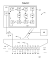
- a device 100 for probing an object 102 comprises an articulated arm 104, an ultrasound probe 106 attached to the articulated arm 104 and arm control means 108 articulated arm adapted to control the articulated arm 104 so that the latter moves the probe 106 relative to the object 102.
- the object 102 is, for example, a mechanical part that it is desired to examine by non-destructive testing or, in a medical context, a part of a human body that it is desired to control in a non-invasive manner.
- the object 102 is immersed in a liquid, such as water 110, and the probe 106 is kept at a distance from the object 102 so that the water 110 separates them.
- the probe 106 firstly comprises a housing 112, that is to say a non-deformable structure element which serves as a reference attached to the probe 106.
- the probe 106 further comprises N transducers 114 1 , ..., 114 N arranged linearly in the housing 112 and attached thereto.
- the transducers 114 1 , ..., 114 N are designed to emit ultrasonic waves towards the object 102 in response to control signals identified under the general reference C, in principal directions parallel to each other, indicated by dashed arrows on the figure 1 , and in a main plane which is that of the figure.
- the transducers 114 1 , ..., 114 N are furthermore designed to detect echoes of the ultrasonic waves reflected on and in the object 102 and to provide measurement signals identified under the general reference M and corresponding to these echoes.
- the probing device 100 further comprises an electronic circuit 116 for controlling the transducers 114 1 , ... 114 N of the probe 106 and for processing the measurement signals M.
- the electronic circuit 116 is connected to the probe 106 in order to transmit the control signals C and receive the measurement signals M.
- the electronic circuit 116 is for example that of a computer.
- the electronic circuit 116 has a central processing unit 118, such as a microprocessor designed to transmit the control signals C to the probe 106 and to receive from the probe 106 the measurement signals M, and a memory 120 in which is recorded a computer program 122.
- the computer program 122 includes an instruction loop 124 to 138 that may be executed one or more times.
- an iteration rank p will be used to distinguish the different iterations of the instruction loop 124 to 138.
- the initial execution of the loop corresponds to p equal to zero (first iteration), while each repetition of the loop corresponds to the value of p : p is equal to one for the first repetition (ie the second iteration), two for the second repetition (ie the third iteration), and so on.
- the computer program 122 first includes instructions 124 designed to determine transmission delays.
- the initial delays E 0 are predefined in the computer program 122. It is for example zero delays (no delay between the transducers 114 1 , ..., 114 N ), especially in the case where no information, even approximate, is known on the geometry of the object 102.
- the initial delays E 0 may be non-zero, and generate for example a wavefront partially adapted to the geometry of the object 102 in first approximation. This variant is for example used in the case where the geometry of the object 102 is already at least partially known.
- the computer program 122 further comprises instructions 126 designed to control the transducers 114 1 , ..., 114 N so that they emit to the object 102 ultrasonic waves having emission delays L p, some by compared to others.
- control signals C p are designed so that the transducers 114 1 ,..., 114 N each emit a pulsed ultrasonic wave of pseudo-time period T , the pulses being thus offset in time with respect to each other from the delays.
- emission L p The emission delays L p are intended to compensate for the differences between the distances separating each transducer from the object 102 for the outward path, so that the Ultrasonic waves emitted by the transducers 114 1 ,..., 114 N reach at the same time the object 102.
- the computer program 122 further comprises instructions 128 designed to receive, at the ith iteration, from the transducers, measured measurement signals M.
- M p M 1 p , ... , M NOT p , or M not p is the measurement signal provided by the transducer 114 n , in particular measuring the echoes due to the reflections of the ultrasonic waves on the object 102.
- the instructions 128 are further designed to record the measurement signals M p .
- instructions 128 are designed to record the measurement signal M not p of each transducer 114 n on a time gate of predetermined duration and beginner, for example, when the command signal VS not p of this transducer 114 n is emitted.
- the control signals C p including the transmission delays L p , the records EN p of the measurement signals M p also include these transmission delays.
- the computer program 122 further includes instructions 130 designed to determine reception offsets.
- R p R 1 p , ... , R NOT p records p , from emission delays L p , R not p being the offset of reception of the recording IN not p .
- reception delays R p The purpose of the reception delays R p is to compensate for the differences between the distances separating each transducer from the object for the return path, so that the ultrasonic waves, which are supposed to be reflected at the same moment on the surface of the object 102 thanks to the emission delays L p , are synchronized and therefore considered in the recording as reaching at the same time the transducers 114 1 , ..., 114 N.
- the computer program 122 therefore comprises instructions 132 designed to shift the records EN p of the measurement signals M p as a function of the reception offsets R p .
- the computer program 122 further includes instructions 134 designed to determine round-trip times.
- t p t 1 p , ... , t NOT p , or t not p is the round-trip time determined from the off-set recording IN not p corresponding to the transducer 114 n .
- the round trip times t p take into account the transmission delays L p and the reception delays R p .
- the round-trip time t not p for each transducer 114 n is determined by detecting, for example, the maximum of the envelope of the corresponding measurement signal M not p , recorded in the offbeat recording IN not p .
- the computer program 122 further comprises instructions 136 designed to determine additional complementary transmission delays E p +1 from the round trip times t p .
- the computer program 122 further comprises instructions 138 designed to evaluate a stopping test, in order to exit the instruction loop 124 to 138 if the stopping test is verified or to continue with a new iteration in the opposite case.
- the instructions 138 are designed to return to the instructions 124 to cause a new iteration of the instruction loop 124 to 138, with the new complementary transmission delays E p +1 , so that the set additional transmission delays includes the p +1 additional emission delays E 1 , ..., E p +1 .
- the index p is incremented by one unit, so that the set of complementary emission delays is at this moment noted E 1 ,..., E p , in accordance with the description of the instructions 124.
- this test means that, if the maximum difference between the round-trip times t p determined by instructions 134 is less than / 4 ⁇ v ⁇ , then it can be considered as a first approximation that these flight times are equal and that the surface of the object 102 has been reached simultaneously by all the waves emitted.
- the instructions 138 may be designed to exit the instruction loop 124 to 138 after a predetermined number of executions of the loop, for example four or five, or p equal to three or four.
- the instructions 138 are designed to pass to instructions 140 for analyzing the last round-robin times calculated by the instructions 134. These last return flight times are then noted t f .
- Tc is the first approximation value of the round-trip times t f considered to be all equal at the output of instruction loop 124 to 138.
- the specular flight time t n between the center of the transducer 114 n and the surface of the object 102 is the minimum time put by a signal emitted by this transducer to return in the form of an echo following a reflection against the surface of the object. It is then significant of the shortest distance separating the transducer 114 n from the surface of the object 102, that is to say the line segment normal to this surface and connecting it to the transducer 114 n : this segment will be qualified in the specular path sequence.
- the computer program 122 further comprises instructions 142 designed to calculate, in a reference (O, x, y) linked to the housing 112 of the probe and defining its control plane, the coordinates (x n , y n ) of the points P n of the surface of the object 102 at the ends of the specular paths associated with the transducers 114 n .
- points P n are defined as part of the surface of the object 102 (more precisely of its intersection with the control plane) and circles (as intersections of spheres with the control plane) respectively centered on the transducers and radii d n : in other words, the surface of the object 102 as represented in the probe control plane is naturally defined as being a curve tangential to the set of respective circles of centers C n (ie the point centers of each transducer 114 n ) and radii d n , or in other words as the envelope of these circles.
- a method of solving this purely geometrical problem is for example given in the document by F.
- the computer program 122 further includes instructions 144 designed to geometrically reconstruct the surface to be detected by linear interpolation. This approximation is valid for objects with no abrupt surface variations between two successive transducers of the probe, which is true in most applications where the controlled surfaces are slowly variable.
- the linear interpolation may be replaced by polynomial interpolation. In the case of a probe with N transducers arranged linearly, it is a profile of the surface of the object 102 in the control plane of the probe is thus obtained.
- the instructions 142 and 144 can be easily adapted to a matrix probe in which the transducers are arranged two-dimensionally in a matrix.
- the principle of geometric reconstruction of the surface of the object 102 is more generally to calculate the tangential surface to a family of spheres of rays d i and whose centers Ci are the transducer centers of the matrix.
- the processing unit 118 executing the instructions 126 controls each transducer 114 n so that it emits ultrasonic waves towards the object 102, the ultrasonic waves emitted by the transducers 114 1 , ..., 114 N having the emission delays L p relative to each other.
- the processing unit 118 executing the instructions 126 transmits each signal control VS not p to the corresponding transducer 114 n , the control signals C p including the transmission delays L p .
- the processing unit 118 executing instructions 128 begins, following the transmission of each control signal VS not p to the corresponding transducer 114 n , the recording of the measurement signal M not p provided by this transducer 114 n .
- each transducer 114 1 ,..., 114 N emits, following the reception of its control signal, a pulsed ultrasonic wave of central frequency f.
- the pulses are time-shifted relative to one another by the emission delays L p .
- each transducer 114 n receives the echoes of the ultrasonic waves reflected on and in the object 102.
- each transducer 114 n provides its measurement signal M not p , in particular measuring the echoes of the ultrasonic waves on the surface of the object 102.
- the processing unit 118 executing the instructions 128 receives this signal M not p and save it in the recording IN not p .
- the processing unit 118 executing the instructions 128 stops recording IN not p signal M not p of the transducer 114 n .
- the processing unit 118 executing the instructions 130 determines the reception offsets R p from the transmission delays L p .
- the processing unit 118 executing the instructions 132 shifts the records EN p of the measurement signals M p as a function of the reception shifts R p , in order to obtain the shifted records EN p .
- the processing unit 118 executing the instructions 136 determines new complementary transmission delays E p +1 from the round trip times t p .
- steps 216 to 222 make it possible to determine complementary transmission delays E p +1 from the measurement signals M p .
- the processing unit 118 executing the instructions 138 determines the stop or the continuation of the instruction loop 124 to 138, and, in the latter case, increments p by one unit before return to step 202.
- step 226 the processing unit 118 executes the instructions 140 to determine the specular flight time t n associated with each transducer 114 n .
- the processing unit 118 executing the instructions 140 determines from each specular flight time t n , each distance d n which separates each transducer 114 n from the surface of the object 102.
- the processing unit 118 executing the instructions 142 determines N-1 points P 1 , ..., P N-1 of the surface of the object 102.
- the processing unit 118 executing the instructions 144 geometrically reconstructs the surface of the object 102 by interpolation, in particular by linear interpolation.
- Steps 226 to 232 perform simple and therefore fast treatments which do not add significant complexity to the entire process of the process. figure 2 .
- the invention provides a "real-time" method of detecting the surface, even complex, of an object whose surface state is not known beforehand. We can therefore qualify this process adaptive for real-time imaging.
- the object 102 is a metal part whose complex geometry is representative of a weld bead 302 that the probe 106 of the sounding device 100 is for probing.
- ultrasonic waves are emitted at steps 208 1 to 208 N by the transducers with emission delays.
- Offset records EN p are then obtained at step 218.
- the amplitude of the envelope of the shifted signals EN p is determined in step 220. They are represented on the figure 4 , in which the vertical axis corresponds to the time, the horizontal axis to the transducers and the amplitude of the envelope to the gray level of the points. This representation is known, as indicated previously, under the name of "B-scan". On this B-scan representation, the round trip distance t not 0 for each transducer 114 n is determined to be the distance separating the time origin from the maximum of the envelope amplitude, i.e., the darkest point on the vertical line corresponding to the transducer 114 n .
- the B-scan representation can be modified by applying a sliding average processing to the measurement signals recorded in the off- axis recordings EN p .
- the complementary emission delays E 1 are then determined in step 222, and the continuation of the execution of the program is decided in step 224 so that a first repetition (second iteration) of the steps is performed ( p is incremented to 1).
- each transducer detects an echo which is the product of the interference between the echo resulting from its own emission of ultrasonic waves and the echoes resulting from the ultrasonic waves emitted by the neighboring transducers. Nevertheless it is possible to adapt the probe apparatus 100 to very complex geometries, such as the weld bead 302, by iterating the steps of the method 200 of the figure 2 .
- the surface of the probed object is substantially horizontal in this last figure, indicating that the probing apparatus 100 is adapted to the geometry of the object 102, that is to say that the wavefront ultrasound formed by the set of waves generated by all the transducers 114 1 ... 114 N has the same curvature as the surface of the weld bead 302. In this last step, all round-trip times can be considered as equal to the same value Tc.
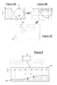
- the Figures 8A, 8B and 8C illustrate the course of steps 226 and 228 on the execution of instructions 140.
- the last transmission delays L f applied to the N transducers and the last reception offsets R f applied to the recordings are represented.
- the Figure 8B are represented the resulting specular flight times, calculated in step 226, for a Tc value of 20 ⁇ s.
- the distances d n which separate each transducer 114 n from the surface of the object 102, that is to say the lengths of the specular paths as calculated in step 228.
- the figure 9 illustrates the result of steps 230 and 232 on the execution of instructions 142 and 144.
- the surface of the object 102 is geometrically reconstructed by linear interpolation from the points P n themselves determined from the positions c n of the transducers 114 n and distances d n .
- the first application of the previously detailed method is the ultrasound imaging of metal parts in real time by focusing at different points.
- This application is illustrated on the figure 10 with an S-scan image obtained by focusing at different angles and at constant depth.
- This technology relies on a constant control of the depth and focusing angle of the ultrasound beam by defining a set of delay laws (a law of delays for each focusing point) evolving over time and applied. to all transducers of the probe.
- this technology requires a perfect knowledge of the geometry of the probed object to be able to adapt the laws of delays accordingly.
- the control would require to reconstruct the surface of the object for each position of the probe in order to adapt the laws of delays to the geometry encountered and to control a constant beam all along the displacement and what whatever the surface state of the probed object.
- a set of delay laws LR is calculated according to this reconstituted surface to focus at different angles and at constant depth.
- An S-scan is obtained, allowing in particular the detection of possible defects D.
- the use of this method thus makes it possible to reconstitute the surface of the object at each position of the probe and to adapt accordingly the laws of delays to control a real-time S-scan image being moved.
- the second application of the previously detailed process relates to a family of applications according to which the ultrasound images are obtained by applying delay laws to focus in the room after reflection on the background.
- This requires a prior knowledge of the geometry of the surface but also the bottom of the object to be inspected, as for example mentioned in the article of A.
- Bazulin et al entitled “Algorithms and software development for automated ultrasonic inspection basing on phased arrays", published following the 10th European Conference on Non-Destructive Testing, June 7-11, 2010, Mosc or, or in the article by A. Fidahoussen et al previously cited.
- the multi-transducer probe is intended to be in contact with the probed object 102, only the bottom surface of the object 102 needs to be reconstituted.
- this bottom surface can be geometrically reconstituted relative to the surface that is in contact with the transducers, the only difference being the velocity of the ultrasonic waves which, in contact, becomes that of the longitudinal waves propagating in the material of the object probe.
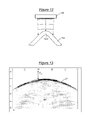
- the figure 11 illustrates in particular the case where the multi-transducer probe is in contact with the object using the technology described in the French patent published under the number FR 2 786 651 .
- the transducers are movably attached to the housing in order to match the geometry of the surface of the object to be probed. It is then provided means for determining the positions of the transducers, and thus the geometry of the surface of the object.
- the strict application of the process of figure 2 then allows, from the knowledge of the surface, to deduce the geometry of the part background.
- the object, referenced 102 ' is a piece having a composite radius 1202 of high angle that the probe 106 of the sounding device 100 is for probing.
- ultrasonic waves are emitted at steps 208 1 to 208 N by the transducers with emission delays.
- Offset records EN p are then obtained at step 218.
- the amplitude of the envelope of the shifted signals EN p is determined in step 220 and reproduced in the corresponding B-scan.
- the appearance of a dark surface line LF, corresponding to the surface echo of the composite radius 1202, is observed, followed by a large noise of structure BF which in no way makes it possible to reveal the presence of a possible defect. in the object 102 '.
- the complementary emission delays E 1 are then determined in step 222, and the continuation of the execution of the program is decided in step 224 so that a first repetition (second iteration) of the steps is performed ( p is incremented to 1).
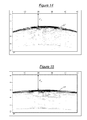
- the dark line LF is substantially horizontal in this last figure, indicating that the ultrasonic wave front formed by the set of waves generated by all the transducers 114 1 ... 114 N has the same curvature as the surface of the radius of composite 1202.
- the internal noise disappeared, leaving appear the actual structure of the object 102 ', in particular a clear line LC indicating the bottom of the object.
- any defect in the object 102 'becomes apparent thanks to a multiple repetition of the previously described loop of steps. In particular, delamination type defects are better detected.
- This third application consists of reconstructing an ultrasound image from the B-scan of the figure 16 .
- This B-scan is shown on the left side of the figure 17 with a fault D detected in the object 102 '.
- the right part is an ultrasound image in which the pixels of the left B-scan are repositioned in the (O, x, y) frame thanks to the knowledge of the geometry of the detected surface and by comparison with its linear shape in the B-scan. Thanks to this transformation, not only the defect D is detected, but moreover it can be located and accurately measured in the reconstructed ultrasound image.
- the computer program instructions could be replaced by electronic circuits dedicated to the functions performed during the execution of these instructions.
- the method according to the invention can be implemented with a mechanical displacement of the probe or by proceeding with a displacement. electronic sub-opening along the total opening of the sensor where the transducers are located.
Landscapes
- Health & Medical Sciences (AREA)
- Life Sciences & Earth Sciences (AREA)
- Physics & Mathematics (AREA)
- General Health & Medical Sciences (AREA)
- Pathology (AREA)
- General Physics & Mathematics (AREA)
- Engineering & Computer Science (AREA)
- Chemical & Material Sciences (AREA)
- Immunology (AREA)
- Biochemistry (AREA)
- Analytical Chemistry (AREA)
- Surgery (AREA)
- Biophysics (AREA)
- Animal Behavior & Ethology (AREA)
- Nuclear Medicine, Radiotherapy & Molecular Imaging (AREA)
- Public Health (AREA)
- Veterinary Medicine (AREA)
- Molecular Biology (AREA)
- Medical Informatics (AREA)
- Heart & Thoracic Surgery (AREA)
- Radiology & Medical Imaging (AREA)
- Biomedical Technology (AREA)
- Signal Processing (AREA)
- Acoustics & Sound (AREA)
- Computer Vision & Pattern Recognition (AREA)
- Investigating Or Analyzing Materials By The Use Of Ultrasonic Waves (AREA)
- Length Measuring Devices Characterised By Use Of Acoustic Means (AREA)
- Gynecology & Obstetrics (AREA)
Claims (10)
- Verfahren zur Rekonstruktion der Geometrie einer Oberfläche (S; LF) eines Objekts (102; 102') durch Echoloten mit einer Ultraschallsonde (106), die mit mehreren Schallgebern (1141, ..., 114N) versehen ist, das die folgenden Schritte umfasst:- Steuern (2041, ..., 204N) der Schallgeber (1141, ..., 114N), damit sie zu der Oberfläche (S; LF) des Objekts Ultraschallwellen senden, die anfängliche Sendeverzögerungen (L0) zueinander aufweisen,- Ausführen mindestens einer darauf folgenden Schleife von Schritten derart, dass nach mindestens einer Iteration eine Wellenfront, die gleichzeitig auf der Oberfläche empfangen wird, erhalten wird:-- Empfangen (2121,..., 212N) von den Schallgebern (1141, ..., 114N) der Zwischenmesssignale (M), die insbesondere Echos aufgrund von Reflexionen der Ultraschallwellen auf der Oberfläche (S; LF) des Objekts zurückzuführen sind,-- Korrigieren (202) der Sendeverzögerungen der Schallgeber (1141, ..., 114N) mit Hilfe der Zwischenmesssignale (M) und Steuern (2041, ..., 204N) der Schallgeber (1141, ..., 114N), damit sie zu der Oberfläche (S; LF) des Objekts Ultraschallwellen senden, die zueinander korrigierte Sendeverzögerungen (Lp) aufweisen,- Empfangen (2121,... 212N) von den Schallgebern (1141, ..., 114N) der abschließenden Messsignale (M), die aus der Reflexion einer Wellenfront resultieren, die gleichzeitig auf der Oberfläche (S; LF) des Objekts empfangen wird,dadurch gekennzeichnet, dass es außerdem die folgenden Schritte umfasst:- Bestimmen (226) der Flugzeiten, Spiegelungsflugzeiten genannt, und die jeweils der Mindestzeit entsprechen, die ein von dem Schallgeber gesendetes Signal braucht, um zu diesem Schallgeber in Form eines Echos im Anschluss an eine Reflexion an der Oberfläche des Objekts zurückzukehren, zwischen jedem Schallgeber (1141, ..., 114N) und der Oberfläche (S; LF) des Objekts ausgehend von den abschließenden Messsignalen (M) und den korrigierten Sendeverzögerungen (Lf), und- geometrische Rekonstitution (228, 230, 232) der Oberfläche (S; LF) des Objekts ausgehend von den bestimmten Spiegelungsflugzeiten.
- Verfahren zur Rekonstruktion einer Oberflächengeometrie (S; LF) nach Anspruch 1, wobei das Bestimmen (226) der Spiegelungsflugzeiten Folgendes umfasst:- Bestimmen einer Hin- Rückflugzeit, die alle Schallgeber (1141, ..., 114N) gemeinsam haben, der Wellenfront, die gleichzeitig auf der Oberfläche (S; LF) des Objekts empfangen wird, und- Berechnung der Spiegelungsflugzeiten ausgehend von dieser Hin- und Rückflugzeit der korrigierten Sendeverzögerungen (Lf) und der an die Schallgeber angewandten Empfangsversätze (Rf).
- Verfahren zur Rekonstruktion einer Oberflächengeometrie (S; LF) nach Anspruch 1 oder 2, wobei die geometrische Rekonstitution (228, 230, 232) der Oberfläche (S; LF) Folgendes umfasst:- Bestimmen (228) von Entfernungen (dn), die jeden Schallgeber (1141, ..., 114N) von der Oberfläche (S; LF) trennen, ausgehend von den bestimmten Spiegelungsflugzeiten,- Berechnung (230) von Koordinaten von Punkten (Pn) der Oberfläche (S; LF) in Abhängigkeit von Koordinaten (cn) der Schallgeber (1141, ..., 114N) und den bestimmten Entfernungen (dn), und- geometrische Rekonstitution (233) der Oberfläche (S; LF) durch Interpolation zwischen diesen Punkten (Pn).
- Verfahren zur Rekonstruktion einer Oberflächengeometrie (S; LF) nach Anspruch 3, wobei die Berechnung (230) der Koordinaten von Punkten (Pn) der Oberfläche (S; LF) auf der Annahme basiert, dass die Oberfläche zu einer Einheit von Kugeln tangential ist, die jeweils auf den Schallgebern (1141, ..., 114N) zentriert sind, und die jeweilige Strahlen, die den bestimmten Entfernungen (dn) entsprechen, haben.
- Verfahren zur Rekonstruktion einer Oberflächengeometrie (S; LF) nach Anspruch 3 oder 4, wobei die Schallgeber (1141, ..., 114N) linear angeordnet sind, und die geometrische Rekonstitution (228, 230, 232) der Oberfläche (S; LF) die Rekonstitution eines Profils dieser Oberfläche in der Prüfebene der Sonde umfasst.
- Verfahren zur Rekonstruktion einer Oberflächengeometrie (S; LF) nach Anspruch 5, wobei N Schallgeber (1141, ..., 114N) linear angeordnet sind, wobei die Koordinaten ihrer Mitten in der Form (cn, 0) in einer Markierung (O, x, y), die mit der Sonde (106) verbunden ist, ausgedrückt werden kann, und wobei die Koordinaten (xn, Yn) der Punkte (Pn) der Oberfläche (S; LF) anhand der folgenden Gleichung berechnet werden:∀n, 1≤N-1,


- Verfahren zur Rekonstruktion einer Oberflächengeometrie (S; LF) nach Anspruch 3 oder 4, wobei die Schallgeber (1141, ..., 114N) zweidimensional als Matrix angeordnet sind und die geometrische Rekonstitution (228, 230, 232) der Oberfläche (S; LF) eine dreidimensionale Rekonstitution dieser Oberfläche umfasst.
- Verfahren zur Rekonstruktion einer Oberflächengeometrie (S; LF) nach einem der Ansprüche 3 bis 7, wobei die geometrische Rekonstitution (228, 230, 232) der Oberfläche (S; LF) durch lineare oder bilineare Interpolation zwischen den Punkten (Pn) erfolgt.
- Computerprogramm (122), das von einem Kommunikationsnetz downloadbar und/oder auf einem von einem Computer lesbaren Medium (120) aufgezeichnet ist und/oder von einem Prozessor (118) ausgeführt werden kann, dadurch gekennzeichnet, dass es Anweisungen zur Ausführung der Schritte eines Verfahrens zur Rekonstruktion der Geometrie einer Oberfläche eines Objekts (102; 102') durch Echoloten nach einem der Ansprüche 1 bis 8 umfasst, wenn das Programm auf einem Computer ausgeführt wird.
- Echolotvorrichtung, die eine Sonde (106) umfasst, die ein Gehäuse (112) und mehrere Schallgeber (1141, ..., 114N) mit Ultraschall umfasst, die an dem Gehäuse (112) befestigt sind, und Mittel zum Steuern und Verarbeiten (116), die konzipiert sind, um:- die Schallgeber (1141, ..., 114N) zu steuern, damit sie zu der Oberfläche (S; LF) des Objekts Ultraschallwellen senden, die anfängliche Sendeverzögerungen (L0) zueinander aufweisen,- mindestens einmal die folgende Schleife von Schritten derart auszuführen, dass nach mindestens einer Iteration eine Wellenfront erhalten wird, die gleichzeitig auf der Oberfläche empfangen wird:dadurch gekennzeichnet, dass die Steuer- und Verarbeitungsmittel (116) außerdem Folgendes umfassen:-- Empfangen von den Schallgebern (1141, ..., 114N) der Signale von zwischen Messungen (M), die insbesondere Echos messen, die auf Reflexionen der Ultraschallwellen auf der Oberfläche (S; LF) des Objekts zurückzuführen sind,-- Korrigieren der Sendeverzögerungen der Schallgeber (1141, ..., 114N) mit Hilfe der Signale von Zwischenmesssignalen (M) und Steuern der Schallgeber (1141, ..., 114N), damit sie zu der Oberfläche (S; LF) des Objekts Ultraschallwellen senden, die zueinander korrigierte Sendeverzögerungen (Lp) aufweisen,- Empfangen von den Schallgebern (1141, ..., 114N) der abschließenden Messsignale (M), die aus der Reflexion einer Wellenfront resultieren, die gleichzeitig auf der Oberfläche (S; LF) des Objekts empfangen wird,- Mittel zum Bestimmen der Flugzeiten, Spiegelungsflugzeiten genannt, und die jeweils der Mindestzeit entsprechen, die ein von einem Schallgeber gesendetes Signal braucht, um zu diesem Schallgeber in Form eines Echos im Anschluss an eine Reflexion an der Oberfläche des Objekts zurückzukehren, zwischen jedem Schallgeber (1141, ..., 114N) und der Oberfläche (S; LF) des Objekts ausgehend von den abschließenden Messsignalen (M) und den korrigierten Sendeverzögerungen (Lf), und- Mittel zur geometrischen Rekonstitution der Oberfläche (S; LF) des Objekts ausgehend von den bestimmten Spiegelungsflugzeiten.
Applications Claiming Priority (2)
| Application Number | Priority Date | Filing Date | Title |
|---|---|---|---|
| FR1160399A FR2982671A1 (fr) | 2011-11-15 | 2011-11-15 | Procede de determination d'une surface d'un objet par sondage echographique, programme d'ordinateur correspondant et dispositif de sondage a ultrasons |
| PCT/FR2012/052507 WO2013072593A1 (fr) | 2011-11-15 | 2012-10-30 | Procede de reconstruction de la geometrie d'une surface d'un objet par sondage echographique, programme d'ordinateur correspondant et dispositif de sondage a ultrasons |
Publications (2)
| Publication Number | Publication Date |
|---|---|
| EP2780699A1 EP2780699A1 (de) | 2014-09-24 |
| EP2780699B1 true EP2780699B1 (de) | 2015-10-14 |
Family
ID=47263443
Family Applications (1)
| Application Number | Title | Priority Date | Filing Date |
|---|---|---|---|
| EP12794408.0A Active EP2780699B1 (de) | 2011-11-15 | 2012-10-30 | Verfahren zur rekonstruktion der geometrie einer oberfläche eines objekts durch echoloten, entsprechendes computerprogramm und vorrichtung zur ultraschallprüfung |
Country Status (7)
| Country | Link |
|---|---|
| US (1) | US9730673B2 (de) |
| EP (1) | EP2780699B1 (de) |
| JP (1) | JP6159730B2 (de) |
| CA (1) | CA2854875A1 (de) |
| ES (1) | ES2559047T3 (de) |
| FR (1) | FR2982671A1 (de) |
| WO (1) | WO2013072593A1 (de) |
Families Citing this family (10)
| Publication number | Priority date | Publication date | Assignee | Title |
|---|---|---|---|---|
| EP2887060A1 (de) | 2013-12-20 | 2015-06-24 | Nederlandse Organisatie voor toegepast- natuurwetenschappelijk onderzoek TNO | Ultraschall-Leitungsprüfungssystem und -verfahren |
| FR3022634B1 (fr) * | 2014-06-19 | 2016-07-15 | Commissariat Energie Atomique | Procede de controle non destructif et sans contact d'un objet par sondage, programme d'ordinateur et dispositif de sondage correspondants |
| FR3057357B1 (fr) * | 2016-10-12 | 2019-04-19 | Commissariat A L'energie Atomique Et Aux Energies Alternatives | Procede et dispositif de detection et de caracterisation d'un element reflecteur dans un objet |
| WO2020028802A1 (en) * | 2018-08-02 | 2020-02-06 | Dexter Stamping Company, Llc | Systems and methods for detecting weld bead conformity |
| DE102018119206A1 (de) * | 2018-08-07 | 2020-02-13 | Salzgitter Mannesmann Forschung Gmbh | Verfahren zum Erfassen der Geometrie eines Bereichs eines Gegenstandes mittels Ultraschall |
| DE202020005983U1 (de) | 2019-04-09 | 2023-12-21 | Dune Labs Inc. | Ultraschall-Durchflussmessung |
| US11143625B2 (en) * | 2019-11-14 | 2021-10-12 | The Boeing Company | Ultrasonic inspection of parts |
| JP7199338B2 (ja) * | 2019-11-21 | 2023-01-05 | 株式会社東芝 | 処理装置、検査システム、処理方法、プログラム、及び記憶媒体 |
| GB2597995A (en) * | 2020-08-14 | 2022-02-16 | Dolphitech As | Ultrasound scanning system with adaptive gating |
| US11933766B2 (en) * | 2021-02-05 | 2024-03-19 | Evident Canada, Inc. | Material profiling for improved sizing accuracy |
Family Cites Families (16)
| Publication number | Priority date | Publication date | Assignee | Title |
|---|---|---|---|---|
| DE69025328T2 (de) * | 1989-08-07 | 1996-09-05 | Hitachi Construction Machinery | Ultraschall-prüfvorrichtung |
| US5750895A (en) * | 1995-07-12 | 1998-05-12 | The United States Of America As Represented By The Administrator Of The National Aeronautics And Space Administration | Method and apparatus for dual amplitude dual time-of-flight ultrasonic imaging |
| FR2786651B1 (fr) | 1998-11-27 | 2002-10-25 | Commissariat Energie Atomique | Transducteur ultrasonore de contact, a elements multiples |
| FR2815723B1 (fr) * | 2000-10-24 | 2004-04-30 | Thomson Csf | Procede systeme et sonde pour l'obtention d'images par l'intermediaire d'ondes emises par une antenne apres reflexion de ces ondes au niveau d'un ensemble servant de cible |
| FR2839157A1 (fr) * | 2002-04-30 | 2003-10-31 | Koninkl Philips Electronics Nv | Systeme d'imagerie ultrasonore a haute resolution laterale |
| CN1326089C (zh) * | 2002-08-21 | 2007-07-11 | 皇家飞利浦电子股份有限公司 | 利用可适配的空间图像组合的超声成像设备 |
| DE10334902B3 (de) * | 2003-07-29 | 2004-12-09 | Nutronik Gmbh | Verfahren und Schaltungsanordnung zur Verarbeitung von Signalen, die bei der zerstörungsfreien Prüfung von Gegenständen durch Reflexion von Ultraschallwellen erzeugt werden |
| JP2008051645A (ja) * | 2006-08-24 | 2008-03-06 | Toshiba Corp | 超音波探傷装置 |
| JP5283888B2 (ja) * | 2006-11-02 | 2013-09-04 | 株式会社東芝 | 超音波診断装置 |
| US20070161904A1 (en) * | 2006-11-10 | 2007-07-12 | Penrith Corporation | Transducer array imaging system |
| WO2009088306A2 (en) * | 2008-01-09 | 2009-07-16 | Angelsen Bjoern A J | Nonlinear elastic imaging with two-frequency elastic pulse complexes |
| US8550998B2 (en) * | 2008-01-09 | 2013-10-08 | Bjørn A. J. Angelsen | Nonlinear elastic wave measurement and imaging with two-frequency elastic wave pulse complexes |
| JP5428249B2 (ja) * | 2008-02-19 | 2014-02-26 | Jfeスチール株式会社 | 管体の肉厚形状測定装置、その方法および管体の製造方法 |
| US9117439B2 (en) * | 2008-03-13 | 2015-08-25 | Supersonic Imagine | Method and apparatus for ultrasound synthetic imagining |
| US8215173B2 (en) * | 2008-08-05 | 2012-07-10 | Roger Spencer | UT method of identifying a stuck joint |
| FR2963443B1 (fr) | 2010-07-28 | 2012-08-17 | Commissariat Energie Atomique | Procede de commande de transducteurs d'une sonde a ultrasons, programme d'ordinateur correspondant et dispositif de sondage a ultrasons |
-
2011
- 2011-11-15 FR FR1160399A patent/FR2982671A1/fr not_active Withdrawn
-
2012
- 2012-10-30 WO PCT/FR2012/052507 patent/WO2013072593A1/fr active Application Filing
- 2012-10-30 EP EP12794408.0A patent/EP2780699B1/de active Active
- 2012-10-30 US US14/358,539 patent/US9730673B2/en not_active Expired - Fee Related
- 2012-10-30 ES ES12794408.0T patent/ES2559047T3/es active Active
- 2012-10-30 CA CA2854875A patent/CA2854875A1/fr not_active Abandoned
- 2012-10-30 JP JP2014541728A patent/JP6159730B2/ja not_active Expired - Fee Related
Also Published As
| Publication number | Publication date |
|---|---|
| JP2014533370A (ja) | 2014-12-11 |
| US20140330127A1 (en) | 2014-11-06 |
| ES2559047T3 (es) | 2016-02-10 |
| JP6159730B2 (ja) | 2017-07-05 |
| US9730673B2 (en) | 2017-08-15 |
| WO2013072593A1 (fr) | 2013-05-23 |
| CA2854875A1 (fr) | 2013-05-23 |
| EP2780699A1 (de) | 2014-09-24 |
| FR2982671A1 (fr) | 2013-05-17 |
Similar Documents
| Publication | Publication Date | Title |
|---|---|---|
| EP2780699B1 (de) | Verfahren zur rekonstruktion der geometrie einer oberfläche eines objekts durch echoloten, entsprechendes computerprogramm und vorrichtung zur ultraschallprüfung | |
| EP2872884B1 (de) | Verfahren zur verarbeitung von ultraschalltestdaten, computerprogramm und entsprechende ultraschalltestvorrichtung | |
| EP2598871B1 (de) | Verfahren zur steuerung einer ultraschallsondenvorrichtung, entsprechendes computerprogramm und ultraschallsondenvorrichtung | |
| EP3084416B1 (de) | Verfahren zur verarbeitung von signalen aus einer ultraschallsondenerfassung, entsprechendes computerprogramm und ultraschallsondenvorrichtung | |
| EP2342582B1 (de) | Verfahren und vorrichtung für sondierung mittels wellenausbreitung | |
| EP3899523B1 (de) | Verfahren zur ultraschallbildgebung mittels zweidimensionaler fourier-transformation, zugehörige ultraschallsondenvorrichtung und computerprogramm | |
| EP3526597B1 (de) | Verfahren und vorrichtung zum erfassen und charakterisieren eines reflektierenden elements in einem objekt | |
| EP1998175B1 (de) | Ultraschallvorhersage über die Deformation eines Werkstücks | |
| WO2016087315A1 (fr) | Procede et dispositif d'imagerie par ultrasons avec filtrage des artefacts dus aux echos de geometrie | |
| FR2907901A1 (fr) | Procede de controle non destructif par ultrasons et sonde de mesure pour la mise en oeuvre du procede | |
| WO2015193604A1 (fr) | Procede de controle non destructif et sans contact d'un objet ayant une surface complexe par sondage, programme d'ordinateur et dispositif de sondage correspondants | |
| FR3140439A1 (fr) | Procédé d’imagerie ultrasonore par transformée de Fourier multidimensionnelle à l’aide de deux transducteurs multiéléments distincts | |
| EP4007914A1 (de) | Verfahren und system zur nichtinvasiven charakterisierung eines heterogenen mediums mittels ultraschall | |
| EP3877758A1 (de) | Verfahren zur rekonstruktion einer dreidimensionalen oberfläche unter verwendung eines ultraschallmatrixsensors | |
| FR3098302A1 (fr) | Dispositif d’imagerie par ondes de surface | |
| FR2855271A1 (fr) | Procede pour l'exploitation et l'analyse d'une structure volumique |
Legal Events
| Date | Code | Title | Description |
|---|---|---|---|
| PUAI | Public reference made under article 153(3) epc to a published international application that has entered the european phase |
Free format text: ORIGINAL CODE: 0009012 |
|
| 17P | Request for examination filed |
Effective date: 20140506 |
|
| AK | Designated contracting states |
Kind code of ref document: A1 Designated state(s): AL AT BE BG CH CY CZ DE DK EE ES FI FR GB GR HR HU IE IS IT LI LT LU LV MC MK MT NL NO PL PT RO RS SE SI SK SM TR |
|
| RIN1 | Information on inventor provided before grant (corrected) |
Inventor name: IAKOVLEVA, EKATERINA Inventor name: ROBERT, SEBASTIEN Inventor name: CASULA, OLIVIER |
|
| DAX | Request for extension of the european patent (deleted) | ||
| GRAP | Despatch of communication of intention to grant a patent |
Free format text: ORIGINAL CODE: EPIDOSNIGR1 |
|
| INTG | Intention to grant announced |
Effective date: 20150511 |
|
| GRAS | Grant fee paid |
Free format text: ORIGINAL CODE: EPIDOSNIGR3 |
|
| GRAA | (expected) grant |
Free format text: ORIGINAL CODE: 0009210 |
|
| AK | Designated contracting states |
Kind code of ref document: B1 Designated state(s): AL AT BE BG CH CY CZ DE DK EE ES FI FR GB GR HR HU IE IS IT LI LT LU LV MC MK MT NL NO PL PT RO RS SE SI SK SM TR |
|
| REG | Reference to a national code |
Ref country code: GB Ref legal event code: FG4D Free format text: NOT ENGLISH |
|
| REG | Reference to a national code |
Ref country code: AT Ref legal event code: REF Ref document number: 755522 Country of ref document: AT Kind code of ref document: T Effective date: 20151015 Ref country code: CH Ref legal event code: EP Ref country code: FR Ref legal event code: PLFP Year of fee payment: 4 |
|
| REG | Reference to a national code |
Ref country code: NL Ref legal event code: MP Effective date: 20151014 |
|
| REG | Reference to a national code |
Ref country code: IE Ref legal event code: FG4D Free format text: LANGUAGE OF EP DOCUMENT: FRENCH |
|
| REG | Reference to a national code |
Ref country code: DE Ref legal event code: R096 Ref document number: 602012011643 Country of ref document: DE |
|
| REG | Reference to a national code |
Ref country code: ES Ref legal event code: FG2A Ref document number: 2559047 Country of ref document: ES Kind code of ref document: T3 Effective date: 20160210 |
|
| REG | Reference to a national code |
Ref country code: LT Ref legal event code: MG4D |
|
| REG | Reference to a national code |
Ref country code: AT Ref legal event code: MK05 Ref document number: 755522 Country of ref document: AT Kind code of ref document: T Effective date: 20151014 |
|
| PG25 | Lapsed in a contracting state [announced via postgrant information from national office to epo] |
Ref country code: IS Free format text: LAPSE BECAUSE OF FAILURE TO SUBMIT A TRANSLATION OF THE DESCRIPTION OR TO PAY THE FEE WITHIN THE PRESCRIBED TIME-LIMIT Effective date: 20160214 Ref country code: NL Free format text: LAPSE BECAUSE OF FAILURE TO SUBMIT A TRANSLATION OF THE DESCRIPTION OR TO PAY THE FEE WITHIN THE PRESCRIBED TIME-LIMIT Effective date: 20151014 Ref country code: NO Free format text: LAPSE BECAUSE OF FAILURE TO SUBMIT A TRANSLATION OF THE DESCRIPTION OR TO PAY THE FEE WITHIN THE PRESCRIBED TIME-LIMIT Effective date: 20160114 Ref country code: LT Free format text: LAPSE BECAUSE OF FAILURE TO SUBMIT A TRANSLATION OF THE DESCRIPTION OR TO PAY THE FEE WITHIN THE PRESCRIBED TIME-LIMIT Effective date: 20151014 Ref country code: HR Free format text: LAPSE BECAUSE OF FAILURE TO SUBMIT A TRANSLATION OF THE DESCRIPTION OR TO PAY THE FEE WITHIN THE PRESCRIBED TIME-LIMIT Effective date: 20151014 |
|
| PG25 | Lapsed in a contracting state [announced via postgrant information from national office to epo] |
Ref country code: FI Free format text: LAPSE BECAUSE OF FAILURE TO SUBMIT A TRANSLATION OF THE DESCRIPTION OR TO PAY THE FEE WITHIN THE PRESCRIBED TIME-LIMIT Effective date: 20151014 Ref country code: SE Free format text: LAPSE BECAUSE OF FAILURE TO SUBMIT A TRANSLATION OF THE DESCRIPTION OR TO PAY THE FEE WITHIN THE PRESCRIBED TIME-LIMIT Effective date: 20151014 Ref country code: AT Free format text: LAPSE BECAUSE OF FAILURE TO SUBMIT A TRANSLATION OF THE DESCRIPTION OR TO PAY THE FEE WITHIN THE PRESCRIBED TIME-LIMIT Effective date: 20151014 Ref country code: GR Free format text: LAPSE BECAUSE OF FAILURE TO SUBMIT A TRANSLATION OF THE DESCRIPTION OR TO PAY THE FEE WITHIN THE PRESCRIBED TIME-LIMIT Effective date: 20160115 Ref country code: LV Free format text: LAPSE BECAUSE OF FAILURE TO SUBMIT A TRANSLATION OF THE DESCRIPTION OR TO PAY THE FEE WITHIN THE PRESCRIBED TIME-LIMIT Effective date: 20151014 Ref country code: RS Free format text: LAPSE BECAUSE OF FAILURE TO SUBMIT A TRANSLATION OF THE DESCRIPTION OR TO PAY THE FEE WITHIN THE PRESCRIBED TIME-LIMIT Effective date: 20151014 Ref country code: PT Free format text: LAPSE BECAUSE OF FAILURE TO SUBMIT A TRANSLATION OF THE DESCRIPTION OR TO PAY THE FEE WITHIN THE PRESCRIBED TIME-LIMIT Effective date: 20160215 Ref country code: PL Free format text: LAPSE BECAUSE OF FAILURE TO SUBMIT A TRANSLATION OF THE DESCRIPTION OR TO PAY THE FEE WITHIN THE PRESCRIBED TIME-LIMIT Effective date: 20151014 |
|
| REG | Reference to a national code |
Ref country code: CH Ref legal event code: PL |
|
| REG | Reference to a national code |
Ref country code: DE Ref legal event code: R097 Ref document number: 602012011643 Country of ref document: DE |
|
| REG | Reference to a national code |
Ref country code: IE Ref legal event code: MM4A |
|
| PG25 | Lapsed in a contracting state [announced via postgrant information from national office to epo] |
Ref country code: MC Free format text: LAPSE BECAUSE OF FAILURE TO SUBMIT A TRANSLATION OF THE DESCRIPTION OR TO PAY THE FEE WITHIN THE PRESCRIBED TIME-LIMIT Effective date: 20151014 Ref country code: CH Free format text: LAPSE BECAUSE OF NON-PAYMENT OF DUE FEES Effective date: 20151031 Ref country code: LI Free format text: LAPSE BECAUSE OF NON-PAYMENT OF DUE FEES Effective date: 20151031 Ref country code: CZ Free format text: LAPSE BECAUSE OF FAILURE TO SUBMIT A TRANSLATION OF THE DESCRIPTION OR TO PAY THE FEE WITHIN THE PRESCRIBED TIME-LIMIT Effective date: 20151014 |
|
| PLBE | No opposition filed within time limit |
Free format text: ORIGINAL CODE: 0009261 |
|
| STAA | Information on the status of an ep patent application or granted ep patent |
Free format text: STATUS: NO OPPOSITION FILED WITHIN TIME LIMIT |
|
| PG25 | Lapsed in a contracting state [announced via postgrant information from national office to epo] |
Ref country code: SM Free format text: LAPSE BECAUSE OF FAILURE TO SUBMIT A TRANSLATION OF THE DESCRIPTION OR TO PAY THE FEE WITHIN THE PRESCRIBED TIME-LIMIT Effective date: 20151014 Ref country code: RO Free format text: LAPSE BECAUSE OF FAILURE TO SUBMIT A TRANSLATION OF THE DESCRIPTION OR TO PAY THE FEE WITHIN THE PRESCRIBED TIME-LIMIT Effective date: 20151014 Ref country code: DK Free format text: LAPSE BECAUSE OF FAILURE TO SUBMIT A TRANSLATION OF THE DESCRIPTION OR TO PAY THE FEE WITHIN THE PRESCRIBED TIME-LIMIT Effective date: 20151014 Ref country code: EE Free format text: LAPSE BECAUSE OF FAILURE TO SUBMIT A TRANSLATION OF THE DESCRIPTION OR TO PAY THE FEE WITHIN THE PRESCRIBED TIME-LIMIT Effective date: 20151014 Ref country code: SK Free format text: LAPSE BECAUSE OF FAILURE TO SUBMIT A TRANSLATION OF THE DESCRIPTION OR TO PAY THE FEE WITHIN THE PRESCRIBED TIME-LIMIT Effective date: 20151014 |
|
| 26N | No opposition filed |
Effective date: 20160715 |
|
| REG | Reference to a national code |
Ref country code: FR Ref legal event code: PLFP Year of fee payment: 5 |
|
| PG25 | Lapsed in a contracting state [announced via postgrant information from national office to epo] |
Ref country code: IE Free format text: LAPSE BECAUSE OF NON-PAYMENT OF DUE FEES Effective date: 20151030 |
|
| PG25 | Lapsed in a contracting state [announced via postgrant information from national office to epo] |
Ref country code: SI Free format text: LAPSE BECAUSE OF FAILURE TO SUBMIT A TRANSLATION OF THE DESCRIPTION OR TO PAY THE FEE WITHIN THE PRESCRIBED TIME-LIMIT Effective date: 20151014 |
|
| PG25 | Lapsed in a contracting state [announced via postgrant information from national office to epo] |
Ref country code: BG Free format text: LAPSE BECAUSE OF FAILURE TO SUBMIT A TRANSLATION OF THE DESCRIPTION OR TO PAY THE FEE WITHIN THE PRESCRIBED TIME-LIMIT Effective date: 20151014 |
|
| PG25 | Lapsed in a contracting state [announced via postgrant information from national office to epo] |
Ref country code: CY Free format text: LAPSE BECAUSE OF FAILURE TO SUBMIT A TRANSLATION OF THE DESCRIPTION OR TO PAY THE FEE WITHIN THE PRESCRIBED TIME-LIMIT Effective date: 20151014 Ref country code: HU Free format text: LAPSE BECAUSE OF FAILURE TO SUBMIT A TRANSLATION OF THE DESCRIPTION OR TO PAY THE FEE WITHIN THE PRESCRIBED TIME-LIMIT; INVALID AB INITIO Effective date: 20121030 |
|
| PG25 | Lapsed in a contracting state [announced via postgrant information from national office to epo] |
Ref country code: BE Free format text: LAPSE BECAUSE OF NON-PAYMENT OF DUE FEES Effective date: 20151031 |
|
| PG25 | Lapsed in a contracting state [announced via postgrant information from national office to epo] |
Ref country code: MT Free format text: LAPSE BECAUSE OF FAILURE TO SUBMIT A TRANSLATION OF THE DESCRIPTION OR TO PAY THE FEE WITHIN THE PRESCRIBED TIME-LIMIT Effective date: 20151014 |
|
| REG | Reference to a national code |
Ref country code: FR Ref legal event code: PLFP Year of fee payment: 6 |
|
| PG25 | Lapsed in a contracting state [announced via postgrant information from national office to epo] |
Ref country code: LU Free format text: LAPSE BECAUSE OF NON-PAYMENT OF DUE FEES Effective date: 20151030 |
|
| PG25 | Lapsed in a contracting state [announced via postgrant information from national office to epo] |
Ref country code: MK Free format text: LAPSE BECAUSE OF FAILURE TO SUBMIT A TRANSLATION OF THE DESCRIPTION OR TO PAY THE FEE WITHIN THE PRESCRIBED TIME-LIMIT Effective date: 20151014 |
|
| REG | Reference to a national code |
Ref country code: FR Ref legal event code: PLFP Year of fee payment: 7 |
|
| PG25 | Lapsed in a contracting state [announced via postgrant information from national office to epo] |
Ref country code: AL Free format text: LAPSE BECAUSE OF FAILURE TO SUBMIT A TRANSLATION OF THE DESCRIPTION OR TO PAY THE FEE WITHIN THE PRESCRIBED TIME-LIMIT Effective date: 20151014 Ref country code: TR Free format text: LAPSE BECAUSE OF FAILURE TO SUBMIT A TRANSLATION OF THE DESCRIPTION OR TO PAY THE FEE WITHIN THE PRESCRIBED TIME-LIMIT Effective date: 20151014 |
|
| PGFP | Annual fee paid to national office [announced via postgrant information from national office to epo] |
Ref country code: DE Payment date: 20211020 Year of fee payment: 10 Ref country code: ES Payment date: 20211117 Year of fee payment: 10 Ref country code: GB Payment date: 20211022 Year of fee payment: 10 |
|
| PGFP | Annual fee paid to national office [announced via postgrant information from national office to epo] |
Ref country code: IT Payment date: 20211029 Year of fee payment: 10 |
|
| REG | Reference to a national code |
Ref country code: DE Ref legal event code: R119 Ref document number: 602012011643 Country of ref document: DE |
|
| GBPC | Gb: european patent ceased through non-payment of renewal fee |
Effective date: 20221030 |
|
| PG25 | Lapsed in a contracting state [announced via postgrant information from national office to epo] |
Ref country code: DE Free format text: LAPSE BECAUSE OF NON-PAYMENT OF DUE FEES Effective date: 20230503 |
|
| PG25 | Lapsed in a contracting state [announced via postgrant information from national office to epo] |
Ref country code: IT Free format text: LAPSE BECAUSE OF NON-PAYMENT OF DUE FEES Effective date: 20221030 Ref country code: GB Free format text: LAPSE BECAUSE OF NON-PAYMENT OF DUE FEES Effective date: 20221030 |
|
| REG | Reference to a national code |
Ref country code: ES Ref legal event code: FD2A Effective date: 20231204 |
|
| PG25 | Lapsed in a contracting state [announced via postgrant information from national office to epo] |
Ref country code: ES Free format text: LAPSE BECAUSE OF NON-PAYMENT OF DUE FEES Effective date: 20221031 |
|
| PG25 | Lapsed in a contracting state [announced via postgrant information from national office to epo] |
Ref country code: ES Free format text: LAPSE BECAUSE OF NON-PAYMENT OF DUE FEES Effective date: 20221031 |
|
| PGFP | Annual fee paid to national office [announced via postgrant information from national office to epo] |
Ref country code: FR Payment date: 20231006 Year of fee payment: 12 |