EP2780154B1 - System and method for fabricating a body part model using multi-material additive manufacturing - Google Patents
System and method for fabricating a body part model using multi-material additive manufacturing Download PDFInfo
- Publication number
- EP2780154B1 EP2780154B1 EP12813472.3A EP12813472A EP2780154B1 EP 2780154 B1 EP2780154 B1 EP 2780154B1 EP 12813472 A EP12813472 A EP 12813472A EP 2780154 B1 EP2780154 B1 EP 2780154B1
- Authority
- EP
- European Patent Office
- Prior art keywords
- materials
- body part
- voxels
- image data
- digital
- Prior art date
- Legal status (The legal status is an assumption and is not a legal conclusion. Google has not performed a legal analysis and makes no representation as to the accuracy of the status listed.)
- Active
Links
- 239000000463 material Substances 0.000 title claims description 239
- 238000000034 method Methods 0.000 title claims description 59
- 239000000654 additive Substances 0.000 title claims description 12
- 230000000996 additive effect Effects 0.000 title claims description 12
- 238000004519 manufacturing process Methods 0.000 title claims description 10
- 230000000704 physical effect Effects 0.000 claims description 23
- 238000003384 imaging method Methods 0.000 claims description 13
- 239000007788 liquid Substances 0.000 claims description 13
- 238000012545 processing Methods 0.000 claims description 12
- 238000003491 array Methods 0.000 claims description 9
- 230000003278 mimic effect Effects 0.000 claims description 9
- 238000002604 ultrasonography Methods 0.000 claims description 6
- 210000001519 tissue Anatomy 0.000 description 34
- 239000004566 building material Substances 0.000 description 30
- 238000002591 computed tomography Methods 0.000 description 21
- 238000003325 tomography Methods 0.000 description 15
- 210000000056 organ Anatomy 0.000 description 13
- 239000000203 mixture Substances 0.000 description 12
- 230000006870 function Effects 0.000 description 10
- 210000000988 bone and bone Anatomy 0.000 description 8
- 210000004872 soft tissue Anatomy 0.000 description 8
- 239000011344 liquid material Substances 0.000 description 6
- 238000007639 printing Methods 0.000 description 6
- 210000004027 cell Anatomy 0.000 description 5
- 238000013459 approach Methods 0.000 description 4
- 239000002131 composite material Substances 0.000 description 4
- 239000000470 constituent Substances 0.000 description 4
- 238000013461 design Methods 0.000 description 4
- 210000000981 epithelium Anatomy 0.000 description 4
- 238000010100 freeform fabrication Methods 0.000 description 4
- 239000007787 solid Substances 0.000 description 4
- 239000012620 biological material Substances 0.000 description 3
- 239000000919 ceramic Substances 0.000 description 3
- 238000011960 computer-aided design Methods 0.000 description 3
- 239000000975 dye Substances 0.000 description 3
- 150000002500 ions Chemical class 0.000 description 3
- 229910052751 metal Inorganic materials 0.000 description 3
- 239000002184 metal Substances 0.000 description 3
- 150000002739 metals Chemical class 0.000 description 3
- 239000007779 soft material Substances 0.000 description 3
- 239000012780 transparent material Substances 0.000 description 3
- 238000010521 absorption reaction Methods 0.000 description 2
- 230000006399 behavior Effects 0.000 description 2
- 230000015572 biosynthetic process Effects 0.000 description 2
- 239000008280 blood Substances 0.000 description 2
- 210000004369 blood Anatomy 0.000 description 2
- 210000001124 body fluid Anatomy 0.000 description 2
- 239000010839 body fluid Substances 0.000 description 2
- 238000011088 calibration curve Methods 0.000 description 2
- 238000004040 coloring Methods 0.000 description 2
- 238000005094 computer simulation Methods 0.000 description 2
- 210000002808 connective tissue Anatomy 0.000 description 2
- 238000002059 diagnostic imaging Methods 0.000 description 2
- 238000010586 diagram Methods 0.000 description 2
- 210000003038 endothelium Anatomy 0.000 description 2
- 239000004615 ingredient Substances 0.000 description 2
- 210000002751 lymph Anatomy 0.000 description 2
- 230000003287 optical effect Effects 0.000 description 2
- 229940068918 polyethylene glycol 400 Drugs 0.000 description 2
- 238000012805 post-processing Methods 0.000 description 2
- 230000011218 segmentation Effects 0.000 description 2
- 238000001228 spectrum Methods 0.000 description 2
- 230000007704 transition Effects 0.000 description 2
- 238000013519 translation Methods 0.000 description 2
- XLYOFNOQVPJJNP-UHFFFAOYSA-N water Substances O XLYOFNOQVPJJNP-UHFFFAOYSA-N 0.000 description 2
- 229920002565 Polyethylene Glycol 400 Polymers 0.000 description 1
- 239000013543 active substance Substances 0.000 description 1
- 238000004458 analytical method Methods 0.000 description 1
- 239000007864 aqueous solution Substances 0.000 description 1
- 210000004204 blood vessel Anatomy 0.000 description 1
- 238000004891 communication Methods 0.000 description 1
- 239000002872 contrast media Substances 0.000 description 1
- 230000001276 controlling effect Effects 0.000 description 1
- 230000002596 correlated effect Effects 0.000 description 1
- 230000000875 corresponding effect Effects 0.000 description 1
- 230000003247 decreasing effect Effects 0.000 description 1
- 230000008021 deposition Effects 0.000 description 1
- 238000012938 design process Methods 0.000 description 1
- 238000009826 distribution Methods 0.000 description 1
- 229940079593 drug Drugs 0.000 description 1
- 239000003814 drug Substances 0.000 description 1
- 230000003511 endothelial effect Effects 0.000 description 1
- 238000005516 engineering process Methods 0.000 description 1
- 238000009499 grossing Methods 0.000 description 1
- 125000004435 hydrogen atom Chemical group [H]* 0.000 description 1
- 238000007654 immersion Methods 0.000 description 1
- 210000003041 ligament Anatomy 0.000 description 1
- 239000011159 matrix material Substances 0.000 description 1
- 210000003205 muscle Anatomy 0.000 description 1
- 239000002105 nanoparticle Substances 0.000 description 1
- 238000013041 optical simulation Methods 0.000 description 1
- 238000005192 partition Methods 0.000 description 1
- 230000000144 pharmacologic effect Effects 0.000 description 1
- 239000011347 resin Substances 0.000 description 1
- 229920005989 resin Polymers 0.000 description 1
- 238000000926 separation method Methods 0.000 description 1
- 239000011343 solid material Substances 0.000 description 1
- 239000002904 solvent Substances 0.000 description 1
- 239000000126 substance Substances 0.000 description 1
- 238000001356 surgical procedure Methods 0.000 description 1
- 238000012360 testing method Methods 0.000 description 1
- 239000002407 tissue scaffold Substances 0.000 description 1
- 238000012549 training Methods 0.000 description 1
Images


Classifications
-
- A—HUMAN NECESSITIES
- A61—MEDICAL OR VETERINARY SCIENCE; HYGIENE
- A61F—FILTERS IMPLANTABLE INTO BLOOD VESSELS; PROSTHESES; DEVICES PROVIDING PATENCY TO, OR PREVENTING COLLAPSING OF, TUBULAR STRUCTURES OF THE BODY, e.g. STENTS; ORTHOPAEDIC, NURSING OR CONTRACEPTIVE DEVICES; FOMENTATION; TREATMENT OR PROTECTION OF EYES OR EARS; BANDAGES, DRESSINGS OR ABSORBENT PADS; FIRST-AID KITS
- A61F2/00—Filters implantable into blood vessels; Prostheses, i.e. artificial substitutes or replacements for parts of the body; Appliances for connecting them with the body; Devices providing patency to, or preventing collapsing of, tubular structures of the body, e.g. stents
- A61F2/02—Prostheses implantable into the body
- A61F2/30—Joints
- A61F2/3094—Designing or manufacturing processes
- A61F2/30942—Designing or manufacturing processes for designing or making customized prostheses, e.g. using templates, CT or NMR scans, finite-element analysis or CAD-CAM techniques
-
- A—HUMAN NECESSITIES
- A61—MEDICAL OR VETERINARY SCIENCE; HYGIENE
- A61C—DENTISTRY; APPARATUS OR METHODS FOR ORAL OR DENTAL HYGIENE
- A61C13/00—Dental prostheses; Making same
- A61C13/0003—Making bridge-work, inlays, implants or the like
- A61C13/0006—Production methods
- A61C13/0019—Production methods using three dimensional printing
-
- B—PERFORMING OPERATIONS; TRANSPORTING
- B29—WORKING OF PLASTICS; WORKING OF SUBSTANCES IN A PLASTIC STATE IN GENERAL
- B29C—SHAPING OR JOINING OF PLASTICS; SHAPING OF MATERIAL IN A PLASTIC STATE, NOT OTHERWISE PROVIDED FOR; AFTER-TREATMENT OF THE SHAPED PRODUCTS, e.g. REPAIRING
- B29C64/00—Additive manufacturing, i.e. manufacturing of three-dimensional [3D] objects by additive deposition, additive agglomeration or additive layering, e.g. by 3D printing, stereolithography or selective laser sintering
- B29C64/10—Processes of additive manufacturing
- B29C64/106—Processes of additive manufacturing using only liquids or viscous materials, e.g. depositing a continuous bead of viscous material
- B29C64/112—Processes of additive manufacturing using only liquids or viscous materials, e.g. depositing a continuous bead of viscous material using individual droplets, e.g. from jetting heads
-
- B—PERFORMING OPERATIONS; TRANSPORTING
- B29—WORKING OF PLASTICS; WORKING OF SUBSTANCES IN A PLASTIC STATE IN GENERAL
- B29C—SHAPING OR JOINING OF PLASTICS; SHAPING OF MATERIAL IN A PLASTIC STATE, NOT OTHERWISE PROVIDED FOR; AFTER-TREATMENT OF THE SHAPED PRODUCTS, e.g. REPAIRING
- B29C64/00—Additive manufacturing, i.e. manufacturing of three-dimensional [3D] objects by additive deposition, additive agglomeration or additive layering, e.g. by 3D printing, stereolithography or selective laser sintering
- B29C64/30—Auxiliary operations or equipment
- B29C64/307—Handling of material to be used in additive manufacturing
- B29C64/314—Preparation
-
- B—PERFORMING OPERATIONS; TRANSPORTING
- B29—WORKING OF PLASTICS; WORKING OF SUBSTANCES IN A PLASTIC STATE IN GENERAL
- B29C—SHAPING OR JOINING OF PLASTICS; SHAPING OF MATERIAL IN A PLASTIC STATE, NOT OTHERWISE PROVIDED FOR; AFTER-TREATMENT OF THE SHAPED PRODUCTS, e.g. REPAIRING
- B29C64/00—Additive manufacturing, i.e. manufacturing of three-dimensional [3D] objects by additive deposition, additive agglomeration or additive layering, e.g. by 3D printing, stereolithography or selective laser sintering
- B29C64/30—Auxiliary operations or equipment
- B29C64/307—Handling of material to be used in additive manufacturing
- B29C64/321—Feeding
- B29C64/336—Feeding of two or more materials
-
- B—PERFORMING OPERATIONS; TRANSPORTING
- B29—WORKING OF PLASTICS; WORKING OF SUBSTANCES IN A PLASTIC STATE IN GENERAL
- B29C—SHAPING OR JOINING OF PLASTICS; SHAPING OF MATERIAL IN A PLASTIC STATE, NOT OTHERWISE PROVIDED FOR; AFTER-TREATMENT OF THE SHAPED PRODUCTS, e.g. REPAIRING
- B29C64/00—Additive manufacturing, i.e. manufacturing of three-dimensional [3D] objects by additive deposition, additive agglomeration or additive layering, e.g. by 3D printing, stereolithography or selective laser sintering
- B29C64/30—Auxiliary operations or equipment
- B29C64/386—Data acquisition or data processing for additive manufacturing
-
- B—PERFORMING OPERATIONS; TRANSPORTING
- B33—ADDITIVE MANUFACTURING TECHNOLOGY
- B33Y—ADDITIVE MANUFACTURING, i.e. MANUFACTURING OF THREE-DIMENSIONAL [3-D] OBJECTS BY ADDITIVE DEPOSITION, ADDITIVE AGGLOMERATION OR ADDITIVE LAYERING, e.g. BY 3-D PRINTING, STEREOLITHOGRAPHY OR SELECTIVE LASER SINTERING
- B33Y40/00—Auxiliary operations or equipment, e.g. for material handling
- B33Y40/10—Pre-treatment
-
- B—PERFORMING OPERATIONS; TRANSPORTING
- B33—ADDITIVE MANUFACTURING TECHNOLOGY
- B33Y—ADDITIVE MANUFACTURING, i.e. MANUFACTURING OF THREE-DIMENSIONAL [3-D] OBJECTS BY ADDITIVE DEPOSITION, ADDITIVE AGGLOMERATION OR ADDITIVE LAYERING, e.g. BY 3-D PRINTING, STEREOLITHOGRAPHY OR SELECTIVE LASER SINTERING
- B33Y50/00—Data acquisition or data processing for additive manufacturing
-
- B—PERFORMING OPERATIONS; TRANSPORTING
- B33—ADDITIVE MANUFACTURING TECHNOLOGY
- B33Y—ADDITIVE MANUFACTURING, i.e. MANUFACTURING OF THREE-DIMENSIONAL [3-D] OBJECTS BY ADDITIVE DEPOSITION, ADDITIVE AGGLOMERATION OR ADDITIVE LAYERING, e.g. BY 3-D PRINTING, STEREOLITHOGRAPHY OR SELECTIVE LASER SINTERING
- B33Y80/00—Products made by additive manufacturing
-
- G—PHYSICS
- G06—COMPUTING; CALCULATING OR COUNTING
- G06F—ELECTRIC DIGITAL DATA PROCESSING
- G06F30/00—Computer-aided design [CAD]
-
- G—PHYSICS
- G06—COMPUTING; CALCULATING OR COUNTING
- G06T—IMAGE DATA PROCESSING OR GENERATION, IN GENERAL
- G06T17/00—Three dimensional [3D] modelling, e.g. data description of 3D objects
-
- G—PHYSICS
- G09—EDUCATION; CRYPTOGRAPHY; DISPLAY; ADVERTISING; SEALS
- G09B—EDUCATIONAL OR DEMONSTRATION APPLIANCES; APPLIANCES FOR TEACHING, OR COMMUNICATING WITH, THE BLIND, DEAF OR MUTE; MODELS; PLANETARIA; GLOBES; MAPS; DIAGRAMS
- G09B23/00—Models for scientific, medical, or mathematical purposes, e.g. full-sized devices for demonstration purposes
- G09B23/28—Models for scientific, medical, or mathematical purposes, e.g. full-sized devices for demonstration purposes for medicine
- G09B23/30—Anatomical models
-
- G—PHYSICS
- G16—INFORMATION AND COMMUNICATION TECHNOLOGY [ICT] SPECIALLY ADAPTED FOR SPECIFIC APPLICATION FIELDS
- G16Z—INFORMATION AND COMMUNICATION TECHNOLOGY [ICT] SPECIALLY ADAPTED FOR SPECIFIC APPLICATION FIELDS, NOT OTHERWISE PROVIDED FOR
- G16Z99/00—Subject matter not provided for in other main groups of this subclass
-
- A—HUMAN NECESSITIES
- A61—MEDICAL OR VETERINARY SCIENCE; HYGIENE
- A61B—DIAGNOSIS; SURGERY; IDENTIFICATION
- A61B5/00—Measuring for diagnostic purposes; Identification of persons
- A61B5/05—Detecting, measuring or recording for diagnosis by means of electric currents or magnetic fields; Measuring using microwaves or radio waves
- A61B5/055—Detecting, measuring or recording for diagnosis by means of electric currents or magnetic fields; Measuring using microwaves or radio waves involving electronic [EMR] or nuclear [NMR] magnetic resonance, e.g. magnetic resonance imaging
-
- A—HUMAN NECESSITIES
- A61—MEDICAL OR VETERINARY SCIENCE; HYGIENE
- A61F—FILTERS IMPLANTABLE INTO BLOOD VESSELS; PROSTHESES; DEVICES PROVIDING PATENCY TO, OR PREVENTING COLLAPSING OF, TUBULAR STRUCTURES OF THE BODY, e.g. STENTS; ORTHOPAEDIC, NURSING OR CONTRACEPTIVE DEVICES; FOMENTATION; TREATMENT OR PROTECTION OF EYES OR EARS; BANDAGES, DRESSINGS OR ABSORBENT PADS; FIRST-AID KITS
- A61F2/00—Filters implantable into blood vessels; Prostheses, i.e. artificial substitutes or replacements for parts of the body; Appliances for connecting them with the body; Devices providing patency to, or preventing collapsing of, tubular structures of the body, e.g. stents
- A61F2/02—Prostheses implantable into the body
- A61F2/30—Joints
- A61F2/3094—Designing or manufacturing processes
- A61F2/30942—Designing or manufacturing processes for designing or making customized prostheses, e.g. using templates, CT or NMR scans, finite-element analysis or CAD-CAM techniques
- A61F2002/30948—Designing or manufacturing processes for designing or making customized prostheses, e.g. using templates, CT or NMR scans, finite-element analysis or CAD-CAM techniques using computerized tomography, i.e. CT scans
-
- A—HUMAN NECESSITIES
- A61—MEDICAL OR VETERINARY SCIENCE; HYGIENE
- A61F—FILTERS IMPLANTABLE INTO BLOOD VESSELS; PROSTHESES; DEVICES PROVIDING PATENCY TO, OR PREVENTING COLLAPSING OF, TUBULAR STRUCTURES OF THE BODY, e.g. STENTS; ORTHOPAEDIC, NURSING OR CONTRACEPTIVE DEVICES; FOMENTATION; TREATMENT OR PROTECTION OF EYES OR EARS; BANDAGES, DRESSINGS OR ABSORBENT PADS; FIRST-AID KITS
- A61F2/00—Filters implantable into blood vessels; Prostheses, i.e. artificial substitutes or replacements for parts of the body; Appliances for connecting them with the body; Devices providing patency to, or preventing collapsing of, tubular structures of the body, e.g. stents
- A61F2/02—Prostheses implantable into the body
- A61F2/30—Joints
- A61F2/3094—Designing or manufacturing processes
- A61F2/30942—Designing or manufacturing processes for designing or making customized prostheses, e.g. using templates, CT or NMR scans, finite-element analysis or CAD-CAM techniques
- A61F2002/30962—Designing or manufacturing processes for designing or making customized prostheses, e.g. using templates, CT or NMR scans, finite-element analysis or CAD-CAM techniques using stereolithography
-
- A—HUMAN NECESSITIES
- A61—MEDICAL OR VETERINARY SCIENCE; HYGIENE
- A61F—FILTERS IMPLANTABLE INTO BLOOD VESSELS; PROSTHESES; DEVICES PROVIDING PATENCY TO, OR PREVENTING COLLAPSING OF, TUBULAR STRUCTURES OF THE BODY, e.g. STENTS; ORTHOPAEDIC, NURSING OR CONTRACEPTIVE DEVICES; FOMENTATION; TREATMENT OR PROTECTION OF EYES OR EARS; BANDAGES, DRESSINGS OR ABSORBENT PADS; FIRST-AID KITS
- A61F2/00—Filters implantable into blood vessels; Prostheses, i.e. artificial substitutes or replacements for parts of the body; Appliances for connecting them with the body; Devices providing patency to, or preventing collapsing of, tubular structures of the body, e.g. stents
- A61F2/02—Prostheses implantable into the body
- A61F2/30—Joints
- A61F2/3094—Designing or manufacturing processes
- A61F2002/30985—Designing or manufacturing processes using three dimensional printing [3DP]
-
- B—PERFORMING OPERATIONS; TRANSPORTING
- B29—WORKING OF PLASTICS; WORKING OF SUBSTANCES IN A PLASTIC STATE IN GENERAL
- B29K—INDEXING SCHEME ASSOCIATED WITH SUBCLASSES B29B, B29C OR B29D, RELATING TO MOULDING MATERIALS OR TO MATERIALS FOR MOULDS, REINFORCEMENTS, FILLERS OR PREFORMED PARTS, e.g. INSERTS
- B29K2071/00—Use of polyethers, e.g. PEEK, i.e. polyether-etherketone or PEK, i.e. polyetherketone or derivatives thereof, as moulding material
- B29K2071/02—Polyalkylene oxides, e.g. PEO, i.e. polyethylene oxide, or derivatives thereof
-
- B—PERFORMING OPERATIONS; TRANSPORTING
- B29—WORKING OF PLASTICS; WORKING OF SUBSTANCES IN A PLASTIC STATE IN GENERAL
- B29L—INDEXING SCHEME ASSOCIATED WITH SUBCLASS B29C, RELATING TO PARTICULAR ARTICLES
- B29L2031/00—Other particular articles
- B29L2031/753—Medical equipment; Accessories therefor
- B29L2031/7532—Artificial members, protheses
Definitions
- the present invention in some embodiments thereof, relates to multi-material Additive Manufacturing (AM) and, more particularly, but not exclusively, to tomographic based physical reconstruction of an object such as a body part with multi-material AM.
- AM multi-material Additive Manufacturing
- AM methods are known to be used to fabricate models of three-dimensional objects, including biological organs.
- AM or Solid Freeform Fabrication (SFF) is a technology enabling fabrication of arbitrarily shaped structures directly from computer data via additive formation steps.
- the basic operation of any SFF system consists of slicing a three-dimensional computer model into thin cross sections, translating the result into two-dimensional position data and feeding the data to control equipment which fabricates a three-dimensional structure in a layerwise manner.
- tomography data e.g. data provided by a Computer Tomography (CT) scanner or Magnetic Resonance Image (MRI) machine to physically reconstruct a biological organ by AM
- CT Computer Tomography
- MRI Magnetic Resonance Image
- the tomography data typically includes grayscale image data of cross sections of the scanned biological organ.
- the tomography data is provided in a Digital Imaging and Communications in Medicine (DICOM) file format.
- DICOM Digital Imaging and Communications in Medicine
- CAD Computer Aided Design
- STL StereoLithography
- STL files only describe surface geometry of a three dimensional object without any representation of possible variations in color, texture and/or mechanical properties within the volume of the three dimensional object. Since variations within the volume cannot be represented with an STL file, much of the information included in the DICOM file is lost during the translation.
- US Patent No. 5,768,134 entitled "Method for making a perfected medical model on the basis of digital image information of a part of the body” describes a method for adding an artificial function element to a model of a body part based on digital image information, e.g. in a CT image prior to segmentation.
- the artificial function element that is added is a function of the digital image information in the form in which all medical data are visible, before segmenting image data pertaining to the body part from the rest of the image. It is described by way of example that a function element, such as an opening indicating the place and direction for boring, can be added as a function of the image information showing additional elements surrounding the body part. It is also described that external information coming from the medical user may be added to the image information and the artificial functional element may also be a function of this additional external information.
- the different modeling materials may be dispensed in different locations within a layer or may be dispensed in same location or adjacent locations so as to allow formation of a composite material.
- the method described includes performing a Boolean comparison between bitmaps representing the desired composite material structure and bitmaps produced by STL files representing the three-dimensional object. It is stated that by eliminating the need for standard CAD software for creating a bitmap representation of the desired composite material structure, the time that would be required for the design process is saved as well as computer memory resources which would usually be required in order to design three-dimensional structures and for the analysis of such three-dimensional structure during the building process.
- the two or more building and/or modeling materials can include a non-solidifiable material that remains in liquid, gel, paste or other non-solid or semi-solid form.
- a second solidifiable material can fully surround or contain the non-solidifiable material during fabrication so that the non-solidifiable material can remain within the object, or alternatively be drained, burnt-out or otherwise removed once the process is complete.
- WO 2005/057436 A1 discloses a method and an apparatus for computer-aided tissue engineering for modeling, design and freeform fabrication of tissue scaffolds, constructs and devices. " Tunable Digital Material Properties for 3D voxel printers", by J. Hiller and H. Lipson, 10-09-2003 , explores the material properties attainable using voxel-based freeform fabrication process.
- a system and method for translating tomography data of a body part into a printable bitmap image representing combinations of modeling materials that can be used to physically reconstruct the body part by multi-material AM According to some embodiments of the present disclosure, a relationship between the tomography data and mechanical properties of tissue making up the body part is defined. In some exemplary embodiments, the combinations of modeling materials for reconstructing the body part are defined to mimic the different mechanical properties as represented by the tomography data.
- the combination of modeling materials include one or more predefined structures designed to enhance representation of one or more of a physical and/or mechanical properties of the body part.
- the method includes defining a relationship between voxel values in the array of voxels and target physical properties for reconstructing the body part; defining a relationship between combinations of modeling materials and their physical properties; and defining a relationship between the voxel values and the material combination responsive to the relationship defined between the voxel values and the target physical properties and the relationship defined between the combinations of modeling materials and their physical properties.
- the relationship is defined by one or more lookup tables.
- the combinations of modeling materials are selected to mimic mechanical properties of the body part on a per voxel basis.
- the image data in the arrays of voxels is translated into an array of digital materials, each digital material formed with a combination of at least two modeling materials, the combination defined by a ratio between the at least two modeling materials.
- the image data in the arrays of voxels is translated into an array of digital materials, each digital material defined as a pattern of modeling material voxels, the pattern formed with at least two different modeling materials.
- each of the digital materials in the array of digital materials is defined with a pre-defined number of modeling material voxels.
- the pre-defined number is selected from a range between 10-1000 modeling material voxels.
- different digital materials in the array of digital material are defined to have different mechanical properties.
- different digital materials are defined to have different elastic properties.
- the different digital materials are defined to have a modulus elasticity ranging between 0.01MPa to 3GPa.
- the digital material is formed from a liquid or gel volume surrounded by a stiffer material.
- the image data is received from one or more of a CT scanner, MRI and ultrasound device.
- the image data is received from a CT scanner and wherein the combinations of modeling materials is defined to simulate an array of densities represented by CT numbers obtained from the CT scanner.
- the method uses one or more additive materials to alter a physical appearance of a portion of the modeling materials in the array.
- the additive material is selected from a group including: dyes metals, ions, ceramics and bio-molecules.
- the additive material is applied responsive to user input.
- the method includes receiving input from a user; and adjusting the combinations of the modeling materials for reconstructing the body part based on the input from the user.
- the processor is operative to define a relationship between voxel values in the array of voxels and target physical properties for reconstructing the body part, to define a relationship between combinations of modeling materials and their physical properties, and to define a relationship between the voxel values and the material combination responsive to the relationship defined between the voxel values and the target physical properties and the relationship defined between the combinations of modeling materials and their physical properties.
- the system comprises a memory unit for storing at least one lookup table, database or equation operative to define a relationship between voxel values in the array of voxels and mechanical properties of the body part.
- the system comprises a memory unit for storing at least one lookup table, database or equation operative to define a relationship between voxel values in the array of voxels and combinations of modeling material that mimic a mechanical property of the body part.
- the processing unit is operative to select combinations of modeling materials that mimic mechanical properties of the body part on a per voxel basis.
- the processing unit is operative to translate the image data in the arrays of voxels into an array of digital materials, each digital material formed with a combination of at least two modeling materials, the combination defined by a ratio between the at least two modeling materials.
- each of the digital materials in the array is defined with a pre-defined number of modeling material voxels.
- the pre-defined number is selected from a range between 10-1000 modeling material voxels.
- different digital materials in the array are defined to have different mechanical properties.
- the digital material is formed from a liquid or gel volume surrounded by a stiffer material.
- the digital material is defined to have a unit size of sub-millimeter macro voxel.
- the image data is received from one more imaging devices selected from a group including a CT scanner, MRI and ultrasound device.
- the printable bitmap images include data for adding one or more additional materials to the combinations of modeling materials.
- the additional material is selected from a group including: dyes metals, ions, ceramics and bio-molecules.
- the present invention in some embodiments thereof, relates to multi-material AM and, more particularly, but not exclusively, tomographic based physical reconstruction of an object such as a body part with multi-material AM.
- a threshold approach is typically used on the image data to identify and/or differentiate between different tissues, e.g. muscle tissue and bone tissue that are imaged.
- contours of each of the identified tissues are defined and used to construct a three dimensional computerized model of each of the tissues to be modeled using a polygon based file and/or an STL file.
- image data showing variations within the tissues and/or gradual changes at the interface between tissues are lost and/or discarded.
- the STL file is typically used to produce the model as an assembly of the identified tissues.
- the present inventors have found that the mechanical feel and appearance of body part models can be better replicated or reconstructed by applying more of the tomography data to additional reconstruct and/or replicate gradual transitions and variations that naturally occur in the body.
- the present inventors have also found that mechanical properties of a body part can be replicated in a model by correlating tomography data, e.g. CT numbers with known mechanical properties of the body part and then defining combinations of different materials at the voxel level that can replicate the designated mechanical properties.
- a system and method for physically reconstructing a body part with multi-material AM where a material composition and/or physical appearance of a body part model is determined and can be altered on a per voxel basis.
- three-dimensional image data e.g. tomography data, e.g. obtained from a medical imaging device such as CT scanner, Magnetic Resonance Imager (MRI), Ultrasound and Optical scanning is constructed from a matrix of voxels or a plurality of slices, each slice including a two dimensional array of voxels.
- the type of information provided by voxel data depends on the imaging device from which it is obtained, e.g.
- CT scanners provide density information and MRI provides information on H atom concentration.
- the voxel information obtained from one or more imaging devices is related to and/or associated with mechanical properties of the tissues.
- voxel information is related to a rigidity and/or compliancy of a tissue.
- a relationship between tomography voxel data and mechanical property is determined based on experimental data and/or known mechanical properties of tissues, e.g. known mechanical properties of bones and ligaments.
- tomography voxel data is used by the multi-material AM device without requiring a CAD system to first construct a computerized model of the body part, for example an STL file.
- a raster file is created for each slice of image data and used as input to the multi-material AM device in place of the STL file(s).
- the different voxel values within a slice of the tomography data are translated into different material compositions during the AM process.
- each voxel of image data is translated into a macrovoxel composed of a plurality of printing voxels, e.g.
- the present inventors have also found that a raster-raster translation is faster, more computationally efficient and requires less software tools, because there is no need to go from raster to mesh and then back to raster, as is done with the STL approach.
- additional information can be added to produce an AM file in the form of a raster file, to include color information, organ type and/or other manually inserted information, e.g. provided by a doctor and/or other user.
- color and transparency levels of different body part regions may be controlled independently to provide accurate optical simulation of the living organ's appearance.
- image data from one or more imaging devices may be combined to create the raster files used as input to the multi-material AM device.
- an automatic or human-aided algorithm can be used to add data for reconstructing one or more features that may be missing in the tomography data, for example due to insufficient resolution of the scan.
- the epithelium and endothelium are usually absent in CT scans due to their small dimensions. However, their locations may be defined as an outer and/or inner boundary of the organ and data for reconstructing the epithelium and endothelium can be added.
- an automatic or human-aided algorithm can be used to add additional data that may improve the appearance and/or mechanical feel and/or stability of the model.
- additional data may define a color for a specific tissue, organ or region.
- connective tissues can be automatically identified, specifically in regions where different tissues connect (e.g. bone and soft tissue).
- such regions can be fabricated using gel or gel-like material e.g. support material to allow better separation between the tissues, for example when serving as a device for surgery training or other education purposes.
- the multi-material AM device operates with at least two materials, e.g. a compliant material and a stiff material.
- one or more lookup tables are used to relate the image data to data in the raster files that defines the material makeup based on the image data.
- a relationship between image data and material composition is defined with one or more look-up tables and/or one or more defined functions, e.g. based on experimental data or based on literature.
- a relationship between image data and material composition is defined manually after experimentally relating one or more image data values, e.g. CT numbers to material properties.
- the multi-material AM device may use additional materials, including materials which remain in liquid state during the entire AM process, said liquid material permitting correct reproduction of extremely soft tissue and/or body fluids, such as blood or lymph.
- the materials employed may be opaque or transparent, and/or have specific coloring depending on the desired application.
- the AM device can make use of additional colored and/or transparent materials for adjusting the appearance of the different regions of synthetic organ.
- a multi-material AM printer e.g. the ConnexTM system by Objet Ltd., Israel, is used to fabricate a model of a body part using two materials having different mechanical properties and different appearances, e.g. a rigid material that is opaque and a compliant material that is transparent.
- a body part model is fabricated with a rigid opaque material used to represent dense material such as found in bone and a compliant transparent material for representing soft and/or fluidic tissues.
- two or more modeling materials can be used to design a variety of digital materials with a spectrum of properties, e.g. ranging between rigid bone and soft fluidic tissues.
- a system 100 receives three dimensional image data of the body part from imaging device 110, e.g. a CT scanner, MRI, ultrasound, or optical scanner (block 210, Fig. 2 ).
- imaging device 110 e.g. a CT scanner, MRI, ultrasound, or optical scanner (block 210, Fig. 2 ).
- the image data is formed from a plurality of two dimensional images each image representing a slice of the body part.
- each slice of image data is a two dimensional array of voxels having values related to a structural and/or material characteristic of the body tissue, e.g. density of the tissue.
- the different voxel values provide contrast for imaging different tissues of the body but the voxels can also be used to determine material and/or physical properties of the body part at each three dimensional voxel location.
- processing unit 125 of system 100 segments image data pertaining to the body part to be modeled from the images captured (block 215, Fig. 2 ).
- processing unit 125 is associated with and/or part of a controller 1250 of system 100.
- segmentation can be performed by imaging device 110.
- processing unit 125 performs image post processing to further enhance one or more features of the image, e.g. three dimensional image and/or individual image slices.
- image data is obtained from a plurality of different imaging devices 110 and processing unit 125 combines the image data from the different imaging devices.
- input from a plurality of different imaging devices is used to further enhance contrast between different soft tissues of the body.
- post processing is performed for smoothing out differences in image data along a seam between different image slices.
- a user may provide additional information with user input device 115.
- a user selects a color and/or transparency level for an identified tissue and/or organ of the body part.
- a user can add a distinguishing feature to differentiate between tissues having similar image voxel values.
- a user selectively employs 3D capable software for viewing and/or providing input.
- a user provides input by marking images displayed by the processing unit and the image data received by the processing unit incorporates the user input.
- one or more lookup tables and/or equations or functions 120 are used by processing unit 125 to convert the original voxel values, e.g. grayscale values of the image data into material data for printing the model of the body part (block 225, Fig. 2 ).
- each voxel of image data is fabricated in the model of the body part with a plurality of voxels of building material/s, e.g. 10-1000 voxels of building material, and/or 300 voxels of building materials.
- digital material is a material formed from a predefined number of voxels of different building materials that are deposited in a contiguous manner and optionally solidified during the AM building process to form a third material (i.e. a digital material).
- the different properties of each material provide for obtaining multi-material combinations having a range of properties between the properties of each of the parent materials as a result of their spatial combination and ratio of their combination.
- the digital material is formed over a plurality of printing layers.
- pre-defined digital material combinations are used rather than pseudo-random mixes. In such case each region having a same image voxel value is replaced by a bitmap from a predefined composition that is linked to that voxel value in a lookup table.
- a different approach can be used, for example error propagation dithering method can be used.
- a support material may take part in the digital material composition.
- Digital material is described in further detail herein below, e.g. in reference to FIG. 4A-4E .
- properties of the digital material are defined to closely resemble a material and/or physical properties of the tissue that is imaged.
- variations in the material properties of the model can be varied on a per voxel basis by altering the constituents and/or the proportions of the constituents of the digital material.
- one or more lookup tables and/or equations 120 are stored in a memory unit 1200 of system 100.
- the lookup table is a database, e.g. a building material database.
- the lookup table provides a relationship between gray scale values and material composition. For example, a gray level of 128 may optionally correspond to 30% compliant material and 70% stiff material.
- a raster file (130) including a bitmap of the digital material data is created for each slice of image data and transmitted to multi-material AM device 140 (block 230, Fig. 2 ) based on which the model is printed one layer at a time (block 240, Fig. 2 ).
- multi-material AM device 140 block 230, Fig. 2
- the model is printed one layer at a time
- one slice of image data is replicated with a plurality of printed layers, e.g. 5-20 printing layers.
- a plurality of raster files, e.g. one for each image data slice is transmitted to the multi-material AM device for printing full model of the body part 150.
- multi-material AM device 140 is equipped with at least two building materials, each with different mechanical properties, e.g. building material 142 and building material 144 that can be dispensed in different proportions and/or patterns to simulate a spectrum of mechanical properties that can be used to replicate variations in properties of the body part.
- multi-material AM device 140 is equipped with additional material, e.g. material 146 that can be used independently from building material 142 and 144 to simulate color, e.g. a dye and/or transparency levels of different regions in the body part, or enhance other physical features of the body part.
- additive materials are used to simulate spatial distribution of contrast agents used during medical imaging. Additional materials may include for example metals, ions, ceramics, bio-molecules and other active substances.
- FIG. 3 showing an exemplary slice of image data obtained with a CT scanner that can be used to fabricate a body part model of a spine with multi-material AM in accordance with some embodiments of the present invention.
- a model of a spine (or a portion of a spine) is formed from images obtained from one or more CT image slices 320 captured from a person.
- CT images include brighter regions 321 reflected from hyper-dense material and darker regions 323 reflected from hypo-dense structures, e.g. soft tissues or liquid material defined by a two dimensional array of CT numbers.
- the CT number may be correlated to the Young's modulus of the corresponding region of the scanned tissue and a model of the spine as imaged may be fabricated by combining a rigid and/or a stiff building material and a compliant, e.g. flexible and/or elastic building material in different proportions.
- a rigid and/or a stiff building material e.g. flexible and/or elastic building material in different proportions.
- brighter regions 321 are modeled with a high percentage of rigid and/or stiff building material while darker regions 323 are modeled with a high percentage of compliant and/or elastic building material.
- a proportion between the two or more building materials used to model each voxel is defined by the CT number of a voxel and by known mechanical properties of the stiffest and most compliant material imaged.
- the stiffness of the stiff material is chosen to be similar or greater than the stiffness of the stiffest tissue to be simulated and the stiffness of the compliant building material is chosen to be close to or less than the stiffness of the most compliant material.
- additional materials which remain in liquid state during the entire AM process may be used to simulate the darkest regions.
- the liquid material is used to simulate very soft tissue and/or body fluids, such as blood or lymph.
- the building materials used may be opaque or transparent, and/or have specific coloring depending on the desired application.
- the AM system can make use of additional colored and/or transparent materials for adjusting the appearance of the different regions of the model.
- gel regions can be formed within a mode to simulate properties of soft tissues or properties of endothelial surfaces, e.g. epithelial tissue that covers organ surfaces.
- a hydrophilic UV curable resin can be used to form hydrophilic material.
- the material upon immersion in aqueous solution, the material will absorb water and swell to form smooth and soft gel that may mimic some of the body's natural soft tissues, e.g. epithelium tissue.
- a digital material is a material that is formed with small volumes, e.g. drops of different building materials 410 and 420 that are deposited simultaneously and optionally solidified during an AM building process.
- Digital materials may be formed in dimensions of unit cells or macro voxels.
- the unit cell and/or macro voxel is defined herein as the smallest volume of digital material that has the defined material properties of the digital material.
- the unit size of the macro voxel corresponds to the unit size represented by one voxel of image data.
- the different building materials have different mechanical properties, e.g. stiffness, flexibility, density, color, transparency, water absorption (%), solvent absorption (%), non-polymerized liquid fraction, nano-particles fraction.
- a digital material is formed by dispensing different building materials over a plurality of different layers.
- the mechanical properties of a digital material are set by defining a ratio between different building materials used to form the digital material.
- a digital material is defined to have a unit size of a millimeter or sub-millimeter macro voxel and each macro voxel contains tens or hundreds of dispensed drops of building material, e.g. 10-1000 micro voxels.
- the geometrical and/or spatial pattern in which the constituents are dispensed may vary according to the desired mechanical and/or physical properties desired.
- the spatial pattern of such deposition can be random or pseudo random ( FIG. 4D ), but in some cases a structured pattern may be desired ( FIG. 4C and 4E ).
- a single building material e.g. single building material 410 ( FIG. 4A ) or single building material 420 ( FIG. 4B ) may be used alone to replicate a high or highest level of a given property.
- a body part model is formed with one stiff and/or rigid material RGD535TM, RGD525TM, FullCure®720, all available by Objet Ltd., Israel and/or compliant material Objet TangoPlusTM, TangoBlackPlusTM, TangoBlackTM, TangoGreyTM, all available by Objet Ltd., Israel.
- the stiffness of the stiff material is chosen as a material that has a stiffness that is similar to or greater than a stiffness of the stiffest tissue to be simulated and the stiffness of the compliant or flexible material is chosen as a material that is similar to or less than that of the least stiff tissue to be simulated.
- the modulus of elasticity of body tissues varies between about 0.01MPa to about 3GPa.
- the present inventors have found that the mechanical behavior or characteristics of most organs and/or body parts can be simulated when fabricating the model with one material have a modulus of elasticity of body tissues of about 0.01MPa and another material with a modulus of elasticity of body tissues varies between about 3 GPa.
- the digital material is not required to be formed using a pre-defined pattern of modeling material.
- the digital material can be defined by a ratio between two or more modeling materials, e.g. parent materials to be pseudo-randomly mixed on the print voxel level. This case typically requires significantly smaller computational resources since the printing voxels can be assigned on-the-fly by randomly dispensing the voxels according to the required mix ratio.
- pseudo-random mixing is that dispensing can take place on a per slice basis without requiring a Z-buffer to reference pattern on alternate slices.
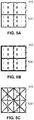
- FIGS. 5A, 5B and 5C showing exemplary compartmental digital material structures where a liquid material is surrounded by the rubber like material.
- a digital material unit cell is defined as compartment; a liquid or gel volume surrounded by a stiffer material.
- Different compartmental unit cells can be defined to produce different mechanical behaviors.
- a very soft gel e.g. having a compressive modulus below 0.1 MPa, liquid, and/or non-solidifying materials 510 is used to simulate soft tissues, connective tissues, blood vessels and other body organs that contain a high fraction of liquids. The present inventors have found that leakage of liquid materials can occur during or after the 3D object fabrication.
- leakage is avoided by fabricating millimeter or sub-millimeter compartmental structures, where each portion of the liquid or soft gel material is surrounded or encapsulated by other solid material, rubber-like building material or digital material, e.g. polyethylene glycol 400 (PEG400), surrounded by a TangoPlus rubber-like material.
- PEG400 polyethylene glycol 400
- the stiffness of a compartmental digital material structure is controlled by controlling overall rubber/liquid ratio, compartment size, wall thickness, stiffness of the rubber-like material, introduction of additional rubber-like filaments or partitions to "reinforce" the liquid region.
- increased stiffness is achieved by increasing thickness of rubber-like building material 520 ( FIG. 5B as compared to FIG. 5A ).
- increased stiffness is achieved by decreasing the defined size of the compartment and/or by changing shape of the compartments ( FIG. 5C ).
- triangular shaped compartments as shown in FIG. 5C are more durable than square shaped compartments shown in FIGS. 5A and 5B .
- the compartments structure may mimic the structure of living body cells.
- FIGS. 6A and 6B showing exemplary graphs of calibration curves for digital materials composed with one soft material (TangoBlackPlusTM) and one rigid material (RGD525TM) that can be used in accordance with some embodiments of the present invention.
- FIG. 6A is an exemplary graph showing a SHORE-A value of a digital material as a function of volume fraction of the soft material in a digital material.
- FIG. 6B is an exemplary graph showing a Young's modulus of a digital material as a function of volume fraction of the rigid material in a digital material.
- the triangular points on the graph represent experimental data and the curve represents an exemplary analytical fit.
- an analytic fit can be used to define one or more equations relating a physical property of a body part in a defined location as determined from imaging and constituents of a digital material to mimic the physical property.
- user input is additionally used to define a physical property of an identified element of a body part.
- FIG. 7A shows reconstruction of a hand using two modeling materials, black material and a clear material, by a known AM technique using STL files, where black material indicates bone and clear material indicates non-bone tissue.
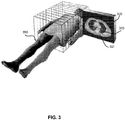
- FIG. 7B shows an exemplary physical reconstruction of a hand using a system and method in accordance with some embodiments of the present invention.
- a hand has been reconstructed with varying combinations of two modeling materials, black material and a clear material. Black was used for the most rigid areas and clear for the most compliant areas, and varying spatial combinations of differing ratios of the two materials are used to replicate varying properties in or within different areas.
- variations in the properties of the bone for example in the joint area have been reconstructed and the joint area has been differentiated.
- a model of a body part can be fabricated using a combination of building materials have various different mechanical and/or physical properties to mimic the properties of the body part.
- compositions, method or structure may include additional ingredients, steps and/or parts, but only if the additional ingredients, steps and/or parts do not materially alter the basic and novel characteristics of the claimed composition, method or structure.
- method refers to manners, means, techniques and procedures for accomplishing a given task including, but not limited to, those manners, means, techniques and procedures either known to, or readily developed from known manners, means, techniques and procedures by practitioners of the chemical, pharmacological, biological, biochemical and medical arts.
Description
- The present invention, in some embodiments thereof, relates to multi-material Additive Manufacturing (AM) and, more particularly, but not exclusively, to tomographic based physical reconstruction of an object such as a body part with multi-material AM.
- AM methods are known to be used to fabricate models of three-dimensional objects, including biological organs. AM or Solid Freeform Fabrication (SFF) is a technology enabling fabrication of arbitrarily shaped structures directly from computer data via additive formation steps. The basic operation of any SFF system consists of slicing a three-dimensional computer model into thin cross sections, translating the result into two-dimensional position data and feeding the data to control equipment which fabricates a three-dimensional structure in a layerwise manner.
- Methods for using tomography data, e.g. data provided by a Computer Tomography (CT) scanner or Magnetic Resonance Image (MRI) machine to physically reconstruct a biological organ by AM are also known. The tomography data typically includes grayscale image data of cross sections of the scanned biological organ. Typically, the tomography data is provided in a Digital Imaging and Communications in Medicine (DICOM) file format.
- In known physical reconstructing methods, a Computer Aided Design (CAD) system is used to convert and/or translate the DICOM file to a three-dimensional computer model in the form of a StereoLithography (STL) file that can be read by AM devices. STL files only describe surface geometry of a three dimensional object without any representation of possible variations in color, texture and/or mechanical properties within the volume of the three dimensional object. Since variations within the volume cannot be represented with an STL file, much of the information included in the DICOM file is lost during the translation.
-
US Patent No. 5,768,134 entitled "Method for making a perfected medical model on the basis of digital image information of a part of the body" describes a method for adding an artificial function element to a model of a body part based on digital image information, e.g. in a CT image prior to segmentation. As described therein, the artificial function element that is added is a function of the digital image information in the form in which all medical data are visible, before segmenting image data pertaining to the body part from the rest of the image. It is described by way of example that a function element, such as an opening indicating the place and direction for boring, can be added as a function of the image information showing additional elements surrounding the body part. It is also described that external information coming from the medical user may be added to the image information and the artificial functional element may also be a function of this additional external information. -
US Patent Publication No. 20100191360 entitled "Solid freeform fabrication using a plurality of modeling materials," assigned to the common assignee, describes inter alia a system and method for fabricating objects using two or more modeling materials in different predetermined combinations, wherein the combinations are produced by dispensing different modeling materials from different dispensing heads. The different modeling materials may be dispensed in different locations within a layer or may be dispensed in same location or adjacent locations so as to allow formation of a composite material. - There is also described a method for defining composite material structures without the need for standard CAD software in order to design the full three-dimensional structure. The method described includes performing a Boolean comparison between bitmaps representing the desired composite material structure and bitmaps produced by STL files representing the three-dimensional object. It is stated that by eliminating the need for standard CAD software for creating a bitmap representation of the desired composite material structure, the time that would be required for the design process is saved as well as computer memory resources which would usually be required in order to design three-dimensional structures and for the analysis of such three-dimensional structure during the building process.
- It is further described that the two or more building and/or modeling materials can include a non-solidifiable material that remains in liquid, gel, paste or other non-solid or semi-solid form. Optionally, a second solidifiable material can fully surround or contain the non-solidifiable material during fabrication so that the non-solidifiable material can remain within the object, or alternatively be drained, burnt-out or otherwise removed once the process is complete. In this way it is described that a hollow or porous model can be provided.
WO 2005/057436 A1 discloses a method and an apparatus for computer-aided tissue engineering for modeling, design and freeform fabrication of tissue scaffolds, constructs and devices. "Tunable Digital Material Properties for 3D voxel printers", by J. Hiller and H. Lipson, 10-09-2003, explores the material properties attainable using voxel-based freeform fabrication process. - According to an aspect of some embodiments of the present disclosure there is provided a system and method for translating tomography data of a body part into a printable bitmap image representing combinations of modeling materials that can be used to physically reconstruct the body part by multi-material AM. According to some embodiments of the present disclosure, a relationship between the tomography data and mechanical properties of tissue making up the body part is defined. In some exemplary embodiments, the combinations of modeling materials for reconstructing the body part are defined to mimic the different mechanical properties as represented by the tomography data. Optionally, the combination of modeling materials include one or more predefined structures designed to enhance representation of one or more of a physical and/or mechanical properties of the body part.
- According to the present invention there is provided a method for physically reconstructing a body part using multi-material additive manufacturing, manner, according to claim 1. According to the present invention, the method includes defining a relationship between voxel values in the array of voxels and target physical properties for reconstructing the body part; defining a relationship between combinations of modeling materials and their physical properties; and defining a relationship between the voxel values and the material combination responsive to the relationship defined between the voxel values and the target physical properties and the relationship defined between the combinations of modeling materials and their physical properties.
- Optionally, the relationship is defined by one or more lookup tables.
- Optionally, the combinations of modeling materials are selected to mimic mechanical properties of the body part on a per voxel basis.
- Optionally, the image data in the arrays of voxels is translated into an array of digital materials, each digital material formed with a combination of at least two modeling materials, the combination defined by a ratio between the at least two modeling materials.
- Optionally, the image data in the arrays of voxels is translated into an array of digital materials, each digital material defined as a pattern of modeling material voxels, the pattern formed with at least two different modeling materials.
- Optionally, each of the digital materials in the array of digital materials is defined with a pre-defined number of modeling material voxels.
- Optionally, the pre-defined number is selected from a range between 10-1000 modeling material voxels.
- Optionally, different digital materials in the array of digital material are defined to have different mechanical properties.
- Optionally, different digital materials are defined to have different elastic properties.
- Optionally, the different digital materials are defined to have a modulus elasticity ranging between 0.01MPa to 3GPa.
- Optionally, the digital material is formed from a liquid or gel volume surrounded by a stiffer material.
- Optionally, the image data is received from one or more of a CT scanner, MRI and ultrasound device.
- Optionally, the image data is received from a CT scanner and wherein the combinations of modeling materials is defined to simulate an array of densities represented by CT numbers obtained from the CT scanner.
- Optionally, the method uses one or more additive materials to alter a physical appearance of a portion of the modeling materials in the array.
- Optionally, the additive material is selected from a group including: dyes metals, ions, ceramics and bio-molecules.
- Optionally, the additive material is applied responsive to user input.
- Optionally, the method includes receiving input from a user; and adjusting the combinations of the modeling materials for reconstructing the body part based on the input from the user.
- According to the present invention, there is provided a system for physically reconstructing a body part using multi-material additive manufacturing according to claim 12. According to the invention, the processor is operative to define a relationship between voxel values in the array of voxels and target physical properties for reconstructing the body part, to define a relationship between combinations of modeling materials and their physical properties, and to define a relationship between the voxel values and the material combination responsive to the relationship defined between the voxel values and the target physical properties and the relationship defined between the combinations of modeling materials and their physical properties.
- Optionally, the system comprises a memory unit for storing at least one lookup table, database or equation operative to define a relationship between voxel values in the array of voxels and mechanical properties of the body part.
- Optionally, the system comprises a memory unit for storing at least one lookup table, database or equation operative to define a relationship between voxel values in the array of voxels and combinations of modeling material that mimic a mechanical property of the body part.
- Optionally, the processing unit is operative to select combinations of modeling materials that mimic mechanical properties of the body part on a per voxel basis.
- Optionally, the processing unit is operative to translate the image data in the arrays of voxels into an array of digital materials, each digital material formed with a combination of at least two modeling materials, the combination defined by a ratio between the at least two modeling materials.
- Optionally, each of the digital materials in the array is defined with a pre-defined number of modeling material voxels.
- Optionally, the pre-defined number is selected from a range between 10-1000 modeling material voxels.
- Optionally, different digital materials in the array are defined to have different mechanical properties.
- Optionally, the digital material is formed from a liquid or gel volume surrounded by a stiffer material.
- Optionally, the digital material is defined to have a unit size of sub-millimeter macro voxel.
- Optionally, the image data is received from one more imaging devices selected from a group including a CT scanner, MRI and ultrasound device.
- Optionally, the printable bitmap images include data for adding one or more additional materials to the combinations of modeling materials.
- Optionally, the additional material is selected from a group including: dyes metals, ions, ceramics and bio-molecules.
- Unless otherwise defined, all technical and/or scientific terms used herein have the same meaning as commonly understood by one of ordinary skill in the art to which the invention pertains. Although methods and materials similar or equivalent to those described herein can be used in the practice or testing of embodiments of the invention, exemplary methods and/or materials are described below. In case of conflict, the patent specification, including definitions, will control. In addition, the materials, methods, and examples are illustrative only and are not intended to be necessarily limiting.
- Some embodiments of the invention are herein described, by way of example only, with reference to the accompanying drawings. With specific reference now to the drawings in detail, it is stressed that the particulars shown are by way of example and for purposes of illustrative discussion of embodiments of the invention. In this regard, the description taken with the drawings makes apparent to those skilled in the art how embodiments of the invention may be practiced.
- In the drawings:
-
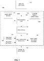
FIG. 1 is a simplified block diagram of an exemplary system for fabricating a body part using multi-material AM in accordance with some embodiments of the present invention; -
FIG. 2 is a simplified flow chart of an exemplary method for fabricating a body part using multi-material AM in accordance with some embodiments of the present invention; -
FIG. 3 is an exemplary slice of image data obtained with a CT scanner that can be used to fabricate a body part model of a spine with multi-material AM in accordance with some embodiments of the present invention; -
FIGs. 4A, 4B, 4C, 4D and 4E are exemplary illustrative representations of different digital material patterns in accordance with some embodiments of the present invention; -
FIGs. 5A, 5B and 5C are exemplary compartmental digital material structures where a liquid material is surrounded by the rubber like material; -
FIGs. 6A and 6B are exemplary graphs of calibration curves for producing a digital material with one soft material and one rigid material in accordance with some embodiments of the present invention; and -
FIGs. 7A and 7B show an exemplary reconstruction of a hand using a known AM method (FIG. 7A ) and using a method in accordance in accordance with some embodiments of the present invention (FIG.7B ). - The present invention, in some embodiments thereof, relates to multi-material AM and, more particularly, but not exclusively, tomographic based physical reconstruction of an object such as a body part with multi-material AM.
- In known methods for making a physical model of a body organ based on tomography and/or image data, a threshold approach is typically used on the image data to identify and/or differentiate between different tissues, e.g. muscle tissue and bone tissue that are imaged. Once identified, contours of each of the identified tissues are defined and used to construct a three dimensional computerized model of each of the tissues to be modeled using a polygon based file and/or an STL file. During this process, image data showing variations within the tissues and/or gradual changes at the interface between tissues are lost and/or discarded. The STL file is typically used to produce the model as an assembly of the identified tissues. Although based on this approach each of the different tissues can be constructed with a different material composition, there is no available information for mimicking variations in properties, e.g. within a single tissue and/or at an interface between tissues.
- The present inventors have found that the mechanical feel and appearance of body part models can be better replicated or reconstructed by applying more of the tomography data to additional reconstruct and/or replicate gradual transitions and variations that naturally occur in the body. The present inventors have also found that mechanical properties of a body part can be replicated in a model by correlating tomography data, e.g. CT numbers with known mechanical properties of the body part and then defining combinations of different materials at the voxel level that can replicate the designated mechanical properties.
- According to an aspect of some embodiments of the present invention, there is provided a system and method for physically reconstructing a body part with multi-material AM where a material composition and/or physical appearance of a body part model is determined and can be altered on a per voxel basis. Typically, three-dimensional image data e.g. tomography data, e.g. obtained from a medical imaging device such as CT scanner, Magnetic Resonance Imager (MRI), Ultrasound and Optical scanning is constructed from a matrix of voxels or a plurality of slices, each slice including a two dimensional array of voxels. The type of information provided by voxel data depends on the imaging device from which it is obtained, e.g. CT scanners provide density information and MRI provides information on H atom concentration. According to some embodiments of the present invention, the voxel information obtained from one or more imaging devices is related to and/or associated with mechanical properties of the tissues. In some exemplary embodiment, voxel information is related to a rigidity and/or compliancy of a tissue. Typically, a relationship between tomography voxel data and mechanical property is determined based on experimental data and/or known mechanical properties of tissues, e.g. known mechanical properties of bones and ligaments.
- According to some embodiments of the present invention, tomography voxel data is used by the multi-material AM device without requiring a CAD system to first construct a computerized model of the body part, for example an STL file. In some exemplary embodiments a raster file is created for each slice of image data and used as input to the multi-material AM device in place of the STL file(s). According to some embodiments of the present invention, the different voxel values within a slice of the tomography data are translated into different material compositions during the AM process. Typically, each voxel of image data is translated into a macrovoxel composed of a plurality of printing voxels, e.g. 10-1000 voxels or 300 voxels of building material. The present inventors have found that by varying the material composition based on changes in tomography voxel values, a more natural physical representation of the different tissues can be replicated including smooth transitions between different types of tissues.
- The present inventors have also found that a raster-raster translation is faster, more computationally efficient and requires less software tools, because there is no need to go from raster to mesh and then back to raster, as is done with the STL approach.
- According to some embodiments of the present invention, additional information can be added to produce an AM file in the form of a raster file, to include color information, organ type and/or other manually inserted information, e.g. provided by a doctor and/or other user. Optionally, color and transparency levels of different body part regions may be controlled independently to provide accurate optical simulation of the living organ's appearance. Optionally, image data from one or more imaging devices may be combined to create the raster files used as input to the multi-material AM device.
- Optionally an automatic or human-aided algorithm can be used to add data for reconstructing one or more features that may be missing in the tomography data, for example due to insufficient resolution of the scan. For example, the epithelium and endothelium are usually absent in CT scans due to their small dimensions. However, their locations may be defined as an outer and/or inner boundary of the organ and data for reconstructing the epithelium and endothelium can be added. Optionally an automatic or human-aided algorithm can be used to add additional data that may improve the appearance and/or mechanical feel and/or stability of the model. Optionally, additional data may define a color for a specific tissue, organ or region. In another example connective tissues can be automatically identified, specifically in regions where different tissues connect (e.g. bone and soft tissue). Optionally, such regions can be fabricated using gel or gel-like material e.g. support material to allow better separation between the tissues, for example when serving as a device for surgery training or other education purposes.
- According to some embodiments of the present invention, the multi-material AM device operates with at least two materials, e.g. a compliant material and a stiff material. Optionally, one or more lookup tables are used to relate the image data to data in the raster files that defines the material makeup based on the image data. Optionally a relationship between image data and material composition is defined with one or more look-up tables and/or one or more defined functions, e.g. based on experimental data or based on literature. Optionally, a relationship between image data and material composition is defined manually after experimentally relating one or more image data values, e.g. CT numbers to material properties.
- Optionally, the multi-material AM device may use additional materials, including materials which remain in liquid state during the entire AM process, said liquid material permitting correct reproduction of extremely soft tissue and/or body fluids, such as blood or lymph. The materials employed may be opaque or transparent, and/or have specific coloring depending on the desired application. Moreover, the AM device can make use of additional colored and/or transparent materials for adjusting the appearance of the different regions of synthetic organ.
- According to some embodiments of the present invention, a multi-material AM printer, e.g. the Connex™ system by Objet Ltd., Israel, is used to fabricate a model of a body part using two materials having different mechanical properties and different appearances, e.g. a rigid material that is opaque and a compliant material that is transparent. In some exemplary embodiments, a body part model is fabricated with a rigid opaque material used to represent dense material such as found in bone and a compliant transparent material for representing soft and/or fluidic tissues. Typically, two or more modeling materials can be used to design a variety of digital materials with a spectrum of properties, e.g. ranging between rigid bone and soft fluidic tissues.
- Reference is now made to
FIG. 1 showing a simplified block diagram of an exemplary system and toFIG. 2 showing a simplified flow chart of an exemplary method, both for fabricating a body part using multi-material AM device in accordance with some embodiments of the present invention. According to some embodiments of the present invention, asystem 100 receives three dimensional image data of the body part fromimaging device 110, e.g. a CT scanner, MRI, ultrasound, or optical scanner (block 210,Fig. 2 ). Typically, the image data is formed from a plurality of two dimensional images each image representing a slice of the body part. Typically, each slice of image data is a two dimensional array of voxels having values related to a structural and/or material characteristic of the body tissue, e.g. density of the tissue. Typically, the different voxel values provide contrast for imaging different tissues of the body but the voxels can also be used to determine material and/or physical properties of the body part at each three dimensional voxel location. - Optionally, processing
unit 125 ofsystem 100 segments image data pertaining to the body part to be modeled from the images captured (block 215,Fig. 2 ). Typically, processingunit 125 is associated with and/or part of acontroller 1250 ofsystem 100. Alternatively, segmentation can be performed byimaging device 110. Optionally, processingunit 125 performs image post processing to further enhance one or more features of the image, e.g. three dimensional image and/or individual image slices. Optionally, image data is obtained from a plurality ofdifferent imaging devices 110 andprocessing unit 125 combines the image data from the different imaging devices. Optionally, input from a plurality of different imaging devices is used to further enhance contrast between different soft tissues of the body. Optionally, post processing is performed for smoothing out differences in image data along a seam between different image slices. - Optionally, in addition to image data received by the processing unit, a user may provide additional information with
user input device 115. Optionally, a user selects a color and/or transparency level for an identified tissue and/or organ of the body part. Optionally, a user can add a distinguishing feature to differentiate between tissues having similar image voxel values. Optionally, a user selectively employs 3D capable software for viewing and/or providing input. Optionally, a user provides input by marking images displayed by the processing unit and the image data received by the processing unit incorporates the user input. - According to some embodiments of the present invention, one or more lookup tables and/or equations or
functions 120 are used by processingunit 125 to convert the original voxel values, e.g. grayscale values of the image data into material data for printing the model of the body part (block 225,Fig. 2 ). In some exemplary embodiments of the present invention, each voxel of image data is fabricated in the model of the body part with a plurality of voxels of building material/s, e.g. 10-1000 voxels of building material, and/or 300 voxels of building materials. As used herein, digital material is a material formed from a predefined number of voxels of different building materials that are deposited in a contiguous manner and optionally solidified during the AM building process to form a third material (i.e. a digital material). The different properties of each material provide for obtaining multi-material combinations having a range of properties between the properties of each of the parent materials as a result of their spatial combination and ratio of their combination. Optionally, the digital material is formed over a plurality of printing layers. Optionally, pre-defined digital material combinations are used rather than pseudo-random mixes. In such case each region having a same image voxel value is replaced by a bitmap from a predefined composition that is linked to that voxel value in a lookup table. Optionally, when the resolution of the image voxel data is higher than the building material voxel, a different approach can be used, for example error propagation dithering method can be used. - Optionally a support material may take part in the digital material composition. Digital material is described in further detail herein below, e.g. in reference to
FIG. 4A-4E . Optionally, properties of the digital material are defined to closely resemble a material and/or physical properties of the tissue that is imaged. Typically, variations in the material properties of the model can be varied on a per voxel basis by altering the constituents and/or the proportions of the constituents of the digital material. Typically, one or more lookup tables and/orequations 120 are stored in amemory unit 1200 ofsystem 100. Optionally the lookup table is a database, e.g. a building material database. Optionally, when the image data is in the form of a gray scale, the lookup table provides a relationship between gray scale values and material composition. For example, a gray level of 128 may optionally correspond to 30% compliant material and 70% stiff material. - According to some embodiments of the present invention, a raster file (130) including a bitmap of the digital material data is created for each slice of image data and transmitted to multi-material AM device 140 (block 230,
Fig. 2 ) based on which the model is printed one layer at a time (block 240,Fig. 2 ). Typically, one slice of image data is replicated with a plurality of printed layers, e.g. 5-20 printing layers. Typically, a plurality of raster files, e.g. one for each image data slice is transmitted to the multi-material AM device for printing full model of thebody part 150. - According to some embodiment of the present invention,
multi-material AM device 140 is equipped with at least two building materials, each with different mechanical properties,e.g. building material 142 andbuilding material 144 that can be dispensed in different proportions and/or patterns to simulate a spectrum of mechanical properties that can be used to replicate variations in properties of the body part. Optionally,multi-material AM device 140 is equipped with additional material,e.g. material 146 that can be used independently frombuilding material - Reference is now made to
FIG. 3 showing an exemplary slice of image data obtained with a CT scanner that can be used to fabricate a body part model of a spine with multi-material AM in accordance with some embodiments of the present invention. According to some embodiments of the present invention, a model of a spine (or a portion of a spine) is formed from images obtained from one or more CT image slices 320 captured from a person. Typically, CT images includebrighter regions 321 reflected from hyper-dense material anddarker regions 323 reflected from hypo-dense structures, e.g. soft tissues or liquid material defined by a two dimensional array of CT numbers. - Optionally, the CT number may be correlated to the Young's modulus of the corresponding region of the scanned tissue and a model of the spine as imaged may be fabricated by combining a rigid and/or a stiff building material and a compliant, e.g. flexible and/or elastic building material in different proportions. Optionally,
brighter regions 321 are modeled with a high percentage of rigid and/or stiff building material whiledarker regions 323 are modeled with a high percentage of compliant and/or elastic building material. Typically, a proportion between the two or more building materials used to model each voxel is defined by the CT number of a voxel and by known mechanical properties of the stiffest and most compliant material imaged. Optionally, the stiffness of the stiff material is chosen to be similar or greater than the stiffness of the stiffest tissue to be simulated and the stiffness of the compliant building material is chosen to be close to or less than the stiffness of the most compliant material. By varying the proportions between the two or more building materials a broad spectrum of mechanical properties can be simulated. - Optionally, additional materials which remain in liquid state during the entire AM process may be used to simulate the darkest regions. Optionally, the liquid material is used to simulate very soft tissue and/or body fluids, such as blood or lymph. The building materials used may be opaque or transparent, and/or have specific coloring depending on the desired application. Moreover, the AM system can make use of additional colored and/or transparent materials for adjusting the appearance of the different regions of the model.
- Optionally, gel regions can be formed within a mode to simulate properties of soft tissues or properties of endothelial surfaces, e.g. epithelial tissue that covers organ surfaces. Optionally a hydrophilic UV curable resin can be used to form hydrophilic material. Optionally, upon immersion in aqueous solution, the material will absorb water and swell to form smooth and soft gel that may mimic some of the body's natural soft tissues, e.g. epithelium tissue.
- Reference is now made to
FIGS. 4A, 4B, 4C, 4D and 4E showing exemplary illustrative representations of different material patterns in accordance with some embodiments of the present invention. According to some embodiments of the present invention, a digital material is a material that is formed with small volumes, e.g. drops ofdifferent building materials - Typically, the different building materials have different mechanical properties, e.g. stiffness, flexibility, density, color, transparency, water absorption (%), solvent absorption (%), non-polymerized liquid fraction, nano-particles fraction. Optionally and/or additionally, a digital material is formed by dispensing different building materials over a plurality of different layers. In some exemplary embodiments, the mechanical properties of a digital material are set by defining a ratio between different building materials used to form the digital material. In some exemplary embodiments, a digital material is defined to have a unit size of a millimeter or sub-millimeter macro voxel and each macro voxel contains tens or hundreds of dispensed drops of building material, e.g. 10-1000 micro voxels.
- In some exemplary embodiments, the geometrical and/or spatial pattern in which the constituents are dispensed may vary according to the desired mechanical and/or physical properties desired. Typically, the spatial pattern of such deposition can be random or pseudo random (
FIG. 4D ), but in some cases a structured pattern may be desired (FIG. 4C and 4E ). Optionally, a single building material, e.g. single building material 410 (FIG. 4A ) or single building material 420 (FIG. 4B ) may be used alone to replicate a high or highest level of a given property. - In some exemplary embodiments, a body part model is formed with one stiff and/or rigid material RGD535™, RGD525™, FullCure®720, all available by Objet Ltd., Israel and/or compliant material Objet TangoPlus™, TangoBlackPlus™, TangoBlack™, TangoGrey™, all available by Objet Ltd., Israel. Optionally, the stiffness of the stiff material is chosen as a material that has a stiffness that is similar to or greater than a stiffness of the stiffest tissue to be simulated and the stiffness of the compliant or flexible material is chosen as a material that is similar to or less than that of the least stiff tissue to be simulated. Typically, the modulus of elasticity of body tissues varies between about 0.01MPa to about 3GPa. The present inventors have found that the mechanical behavior or characteristics of most organs and/or body parts can be simulated when fabricating the model with one material have a modulus of elasticity of body tissues of about 0.01MPa and another material with a modulus of elasticity of body tissues varies between about 3 GPa.
- Optionally, the digital material is not required to be formed using a pre-defined pattern of modeling material. Rather, the digital material can be defined by a ratio between two or more modeling materials, e.g. parent materials to be pseudo-randomly mixed on the print voxel level. This case typically requires significantly smaller computational resources since the printing voxels can be assigned on-the-fly by randomly dispensing the voxels according to the required mix ratio. Another advantage of pseudo-random mixing is that dispensing can take place on a per slice basis without requiring a Z-buffer to reference pattern on alternate slices.
- Reference is now made to
FIGS. 5A, 5B and 5C showing exemplary compartmental digital material structures where a liquid material is surrounded by the rubber like material. In some embodiments a digital material unit cell is defined as compartment; a liquid or gel volume surrounded by a stiffer material. Different compartmental unit cells can be defined to produce different mechanical behaviors. In some exemplary embodiments, a very soft gel e.g. having a compressive modulus below 0.1 MPa, liquid, and/ornon-solidifying materials 510 is used to simulate soft tissues, connective tissues, blood vessels and other body organs that contain a high fraction of liquids. The present inventors have found that leakage of liquid materials can occur during or after the 3D object fabrication. In some exemplary embodiments, leakage is avoided by fabricating millimeter or sub-millimeter compartmental structures, where each portion of the liquid or soft gel material is surrounded or encapsulated by other solid material, rubber-like building material or digital material, e.g. polyethylene glycol 400 (PEG400), surrounded by a TangoPlus rubber-like material. - In some exemplary embodiments, the stiffness of a compartmental digital material structure is controlled by controlling overall rubber/liquid ratio, compartment size, wall thickness, stiffness of the rubber-like material, introduction of additional rubber-like filaments or partitions to "reinforce" the liquid region. Optionally, increased stiffness is achieved by increasing thickness of rubber-like building material 520 (
FIG. 5B as compared toFIG. 5A ). Optionally, increased stiffness is achieved by decreasing the defined size of the compartment and/or by changing shape of the compartments (FIG. 5C ). Optionally, triangular shaped compartments as shown inFIG. 5C are more durable than square shaped compartments shown inFIGS. 5A and 5B . Optionally, the compartments structure may mimic the structure of living body cells. - Reference is now made to
FIGS. 6A and 6B showing exemplary graphs of calibration curves for digital materials composed with one soft material (TangoBlackPlus™) and one rigid material (RGD525™) that can be used in accordance with some embodiments of the present invention.FIG. 6A is an exemplary graph showing a SHORE-A value of a digital material as a function of volume fraction of the soft material in a digital material.FIG. 6B is an exemplary graph showing a Young's modulus of a digital material as a function of volume fraction of the rigid material in a digital material. The triangular points on the graph represent experimental data and the curve represents an exemplary analytical fit. Optionally, an analytic fit can be used to define one or more equations relating a physical property of a body part in a defined location as determined from imaging and constituents of a digital material to mimic the physical property. Optionally, user input is additionally used to define a physical property of an identified element of a body part. - Reference is now made to
FIGS. 7A and 7B showing exemplary reconstructions of a hand.FIG. 7A shows reconstruction of a hand using two modeling materials, black material and a clear material, by a known AM technique using STL files, where black material indicates bone and clear material indicates non-bone tissue. In comparison,FIG. 7B shows an exemplary physical reconstruction of a hand using a system and method in accordance with some embodiments of the present invention. As can be seen inFIG. 7B , a hand has been reconstructed with varying combinations of two modeling materials, black material and a clear material. Black was used for the most rigid areas and clear for the most compliant areas, and varying spatial combinations of differing ratios of the two materials are used to replicate varying properties in or within different areas. Thus, by using the system and method in accordance with some embodiments of the present invention, variations in the properties of the bone for example in the joint area have been reconstructed and the joint area has been differentiated. - It is noted that although most of the embodiments have been described in reference to fabricating a model of a body part, the embodiments of the present invention are not limited in that respect and that the same system and methods can be used for fabricating models of other objects formed from a plurality of different materials.
- It is further noted that although most of the embodiments have been described in reference to fabricating a model of a body part using a combination of stiff and compliant material, the embodiments of the present invention are not limited in that respect. In other embodiments of the present invention, a model of a body part can be fabricated using a combination of building materials have various different mechanical and/or physical properties to mimic the properties of the body part.
- The terms "comprises", "comprising", "includes", "including", "having" and their conjugates mean "including but not limited to".
- The term "consisting of means "including and limited to".
- The term "consisting essentially of" means that the composition, method or structure may include additional ingredients, steps and/or parts, but only if the additional ingredients, steps and/or parts do not materially alter the basic and novel characteristics of the claimed composition, method or structure.
- As used herein the term "method" refers to manners, means, techniques and procedures for accomplishing a given task including, but not limited to, those manners, means, techniques and procedures either known to, or readily developed from known manners, means, techniques and procedures by practitioners of the chemical, pharmacological, biological, biochemical and medical arts.
- It is appreciated that certain features of the invention, which are, for clarity, described in the context of separate embodiments, may also be provided in combination in a single embodiment. Conversely, various features of the invention, which are, for brevity, described in the context of a single embodiment, may also be provided separately or in any suitable sub-combination or as suitable in any other described embodiment of the invention. Certain features described in the context of various embodiments are not to be considered essential features of those embodiments, unless the embodiment is inoperative without those elements.
Claims (15)
- A method for physically reconstructing a body part using multi-material additive manufacturing, the method comprising:receiving image data of the body part in the form of arrays of voxels, each array of voxels representing image data pertaining to cross-section of the body part;defining a relationship between voxel values in the array of voxels and target physical properties for reconstructing the part;defining a relationship between combinations of modeling materials and their physical properties; anddefining a relationship between the voxel values and the material combination responsive to the relationship defined between the voxel values and the target physical properties and the relationship defined between the combinations of modeling materials and their physical properties;translating the image data in the arrays of voxels to printable bitmap images representing combinations of modeling materials for reconstructing the body part; anddispensing the combinations of modeling materials responsive to the bitmap images in a layerwise manner.
- The method according to claim 1, wherein the relationship is defined by one or more lookup tables.
- The method according to claim 1 or claim 2, wherein the combinations of modeling materials are selected to mimic mechanical properties of the body part on a per voxel basis.
- The method according to any one of claims 1-3, wherein the image data in the arrays of voxels is translated into an array of digital materials, each digital material formed with a combination of at least two modeling materials, the combination defined by a ratio between the at least two modeling materials, and a pattern of modeling material voxels formed with at least two different modeling materials.
- The method according to claim 4, wherein each of the digital materials in the array of digital materials is defined with a pre-defined number of modeling material voxels
- The method according to claim 4 or claim 5, wherein different digital materials in the array of digital material are defined to have different mechanical properties.
- The method according to claim 6, wherein different digital materials are defined to have different elastic properties
- The method according to any one of claims 4-7, wherein the digital material is formed from a liquid or gel volume surrounded by a stiffer material.
- The method of any one of claims 1-8, wherein the image data is received from one or more of a CT scanner, MRI and ultrasound device and wherein the combinations of modeling materials is defined to simulate an array of densities represented by CT numbers obtained from the CT scanner when the image data is received from a CT scanner.
- The method of any one of claims 1-9, using one or more additional materials to alter a physical appearance of a portion of the body part that is reconstructed.
- The method of any one of claims 1-10, comprising:receiving input from a user; andadjusting the combinations of the modeling materials for reconstructing the body part based on the input from the user.
- A system for physically reconstructing a body part using multi-material additive manufacturing comprising:a controller operative to receive image data of the body part in the form of arrays of voxels, each array of voxels representing image data pertaining to cross-section of the body part;a processing unit operative to:define a relationship between voxel values in the array of voxels and target physical properties for reconstructing the body part;define a relationship between combinations of modeling materials and their physical properties;define a relationship between the voxel values and the material combination responsive to the relationship defined between the voxel values and the target physical properties and the relationship defined between the combinations of modeling materials and their physical properties; andtranslate the image data in the arrays of voxels to printable bitmap images representing combinations of modeling materials for reconstructing the body part; anda multi-material additive manufacturing device for dispensing the combinations of modeling materials responsive to the bitmap images in a layerwise manner.
- The system according to claim 12, wherein the processing unit is operative to translate the image data in the arrays of voxels into an array of digital materials, wherein the digital material is defined to have a unit size of sub-millimeter macro voxel.
- The system according to claim 12 or claim 13, wherein the image data is received from one more imaging devices selected from a group including a CT scanner, MRI and ultrasound device.
- The system of any one of claims 12-14, wherein the printable bitmap images includes data for adding one or more additional materials to the combinations of modeling materials.
Priority Applications (1)
| Application Number | Priority Date | Filing Date | Title |
|---|---|---|---|
| EP18155660.6A EP3342581A1 (en) | 2011-11-17 | 2012-11-15 | Body part model fabricated using multi-material additive manufacturing |
Applications Claiming Priority (2)
| Application Number | Priority Date | Filing Date | Title |
|---|---|---|---|
| US201161560822P | 2011-11-17 | 2011-11-17 | |
| PCT/IB2012/056462 WO2013072874A1 (en) | 2011-11-17 | 2012-11-15 | System and method for fabricating a body part model using multi-material additive manufacturing |
Related Child Applications (3)
| Application Number | Title | Priority Date | Filing Date |
|---|---|---|---|
| EP18155660.6A Division-Into EP3342581A1 (en) | 2011-11-17 | 2012-11-15 | Body part model fabricated using multi-material additive manufacturing |
| EP18155660.6A Addition EP3342581A1 (en) | 2011-11-17 | 2012-11-15 | Body part model fabricated using multi-material additive manufacturing |
| EP18155660.6A Division EP3342581A1 (en) | 2011-11-17 | 2012-11-15 | Body part model fabricated using multi-material additive manufacturing |
Publications (2)
| Publication Number | Publication Date |
|---|---|
| EP2780154A1 EP2780154A1 (en) | 2014-09-24 |
| EP2780154B1 true EP2780154B1 (en) | 2018-03-28 |
Family
ID=47553279
Family Applications (2)
| Application Number | Title | Priority Date | Filing Date |
|---|---|---|---|
| EP12813472.3A Active EP2780154B1 (en) | 2011-11-17 | 2012-11-15 | System and method for fabricating a body part model using multi-material additive manufacturing |
| EP18155660.6A Pending EP3342581A1 (en) | 2011-11-17 | 2012-11-15 | Body part model fabricated using multi-material additive manufacturing |
Family Applications After (1)
| Application Number | Title | Priority Date | Filing Date |
|---|---|---|---|
| EP18155660.6A Pending EP3342581A1 (en) | 2011-11-17 | 2012-11-15 | Body part model fabricated using multi-material additive manufacturing |
Country Status (10)
| Country | Link |
|---|---|
| US (2) | US9999509B2 (en) |
| EP (2) | EP2780154B1 (en) |
| JP (3) | JP6188708B2 (en) |
| KR (2) | KR102176893B1 (en) |
| CN (2) | CN106626423A (en) |
| DK (1) | DK2780154T3 (en) |
| ES (1) | ES2671252T3 (en) |
| HK (1) | HK1203172A1 (en) |
| IL (3) | IL234456B (en) |
| WO (1) | WO2013072874A1 (en) |
Cited By (1)
| Publication number | Priority date | Publication date | Assignee | Title |
|---|---|---|---|---|
| EP3658352B1 (en) * | 2017-07-28 | 2023-09-27 | Stratasys Ltd. | Additive manufacturing processes employing a material featuring properties of a soft bodily tissue |
Families Citing this family (75)
| Publication number | Priority date | Publication date | Assignee | Title |
|---|---|---|---|---|
| CN106626423A (en) | 2011-11-17 | 2017-05-10 | 斯特拉塔西斯公司 | System using composite material lamination to manufacture body part model and manufacturing method |
| CN103393486B (en) * | 2013-08-13 | 2015-09-02 | 华中科技大学同济医学院附属同济医院 | 3D is utilized to print the method for preparation cranial bone flap to be repaired |
| AU2014331799B2 (en) * | 2013-10-11 | 2018-05-17 | Advanced Solutions Life Sciences, Llc | System and workstation for the design, fabrication and assembly of bio-material constructs |
| US10292670B2 (en) * | 2013-12-04 | 2019-05-21 | Elekta Ltd. | Method and system for dose calculation based on continuous material indexing |
| DE102014200402A1 (en) * | 2014-01-13 | 2015-07-16 | Bayerische Motoren Werke Aktiengesellschaft | A method of manufacturing a component comprising at least one material layer having at least two different materials and components with regard to a material property |
| DE102014220760A1 (en) * | 2014-10-14 | 2016-04-14 | Siemens Aktiengesellschaft | Method of making a phantom for medical imaging |
| CN107107462A (en) | 2014-10-21 | 2017-08-29 | 斯特拉塔西斯公司 | Use the three-dimensional ink-jet printing method of ring-opening metathesis polymerization |
| CN107005621B (en) * | 2014-10-29 | 2019-06-21 | 惠普发展公司,有限责任合伙企业 | The method that at least part of 3D object is converted into the format suitable for printing |
| EP3023229B1 (en) * | 2014-11-24 | 2021-09-29 | Fraunhofer-Gesellschaft zur Förderung der angewandten Forschung e.V. | A method for three-dimensional color printing and a three-dimensional color printing device |
| CN105719545A (en) * | 2014-12-02 | 2016-06-29 | 天津市医学堂科技有限公司 | Puncture module for medical teaching |
| DE102014226445A1 (en) * | 2014-12-18 | 2016-06-23 | Siemens Healthcare Gmbh | Method for producing a 3D facsimile of an object and system for producing a 3D facsimile of an object |
| CN105984146A (en) * | 2015-01-30 | 2016-10-05 | 深圳市亿思达科技集团有限公司 | Manufacturing method of 3D object and 3D printing device |
| US10688727B2 (en) | 2015-01-30 | 2020-06-23 | Hewlett-Packard Development Company, L.P. | Control data based on sub-regions with non-variable object properties |
| GB2536062A (en) * | 2015-03-06 | 2016-09-07 | Sony Computer Entertainment Inc | System, device and method of 3D printing |
| DE102015204237A1 (en) * | 2015-03-10 | 2016-09-15 | Siemens Healthcare Gmbh | Method and device for producing a model finding object |
| JP6306532B2 (en) | 2015-03-25 | 2018-04-04 | 富士フイルム株式会社 | Three-dimensional data processing system, method, program, three-dimensional model, and three-dimensional model shaping apparatus |
| US10678217B2 (en) | 2015-04-20 | 2020-06-09 | Hewlett-Packard Development Company, L.P. | Creating a voxel representation of a three dimensional (3-D) object |
| EP3292487B1 (en) * | 2015-04-24 | 2022-10-05 | Hewlett-Packard Development Company, L.P. | Three dimensional object data |
| CN107209958B (en) * | 2015-04-24 | 2021-06-25 | 惠普发展公司,有限责任合伙企业 | Three-dimensional object representation |
| US10338568B2 (en) * | 2015-04-24 | 2019-07-02 | Hewlett-Packard Development Company, L.P. | Determining halftone schemes |
| KR101652482B1 (en) * | 2015-05-12 | 2016-08-30 | 메디컬아이피 주식회사 | Transparent product manufacturing method and transparent product by the method |
| EP3296085B1 (en) | 2015-05-12 | 2021-12-22 | Medicalip Co., Ltd. | Method for producing transparent three-dimensional object, and transparent three-dimensional object produced by same |
| CN107961073A (en) * | 2015-07-15 | 2018-04-27 | 福建师范大学 | A kind of orthopaedics inside-fixture forming method for reducing stress shielding |
| US10343335B2 (en) | 2015-07-15 | 2019-07-09 | Hewlett-Packard Development Company, L.P. | Three dimensional material distribution using octrees |
| KR20170014617A (en) * | 2015-07-30 | 2017-02-08 | 삼성에스디에스 주식회사 | Method for generating bitmap of 3-dimensional model, apparatus and system for executing the method |
| DE202015104282U1 (en) | 2015-08-13 | 2015-08-26 | Paul Jahnke | Model and system for use in an imaging process |
| US10751943B2 (en) * | 2015-08-24 | 2020-08-25 | Siemens Healthcare Gmbh | Personalized creation from medical imaging |
| US10733911B2 (en) * | 2015-10-14 | 2020-08-04 | Humanetics Innovative Solutions, Inc. | Three-dimensional ribs and method of three-dimensional printing of ribs for crash test dummy |
| US10395561B2 (en) | 2015-12-07 | 2019-08-27 | Humanetics Innovative Solutions, Inc. | Three-dimensionally printed internal organs for crash test dummy |
| JP6868019B2 (en) * | 2015-10-29 | 2021-05-12 | ストラタシス リミテッド | Material consumption in additive manufacturing |
| WO2017099790A1 (en) * | 2015-12-11 | 2017-06-15 | Hewlett-Packard Development Company, L.P. | Print material selection |
| JP6572142B2 (en) * | 2016-01-26 | 2019-09-04 | キヤノン株式会社 | Information processing apparatus, control method, and program |
| WO2017132582A1 (en) * | 2016-01-29 | 2017-08-03 | Massachusetts Institute Of Technology | Techniques for color contoning in additive fabrication and related systems and methods |
| KR102482062B1 (en) * | 2016-02-05 | 2022-12-28 | 주식회사바텍 | Dental three-dimensional scanner using color pattern |
| EP3411424B1 (en) | 2016-02-05 | 2024-01-10 | Stratasys Ltd. | Three-dimensional inkjet printing using polyamide-forming materials |
| WO2017134674A1 (en) | 2016-02-05 | 2017-08-10 | Stratasys Ltd. | Three-dimensional inkjet printing using ring-opening metathesis polymerization |
| US11179879B2 (en) | 2016-02-07 | 2021-11-23 | Stratasys Ltd. | Three-dimensional printing combining ring-opening metathesis polymerization and free radical polymerization |
| WO2017147412A1 (en) * | 2016-02-25 | 2017-08-31 | Stratasys Ltd. | Gpu material assignment for 3d printing using 3d distance fields |
| JP6461846B2 (en) * | 2016-03-24 | 2019-01-30 | 株式会社東芝 | Additive manufacturing apparatus and program |
| WO2017187434A1 (en) | 2016-04-26 | 2017-11-02 | Stratasys Ltd. | Three-dimensional inkjet printing using ring-opening metathesis polymerization |
| US10926000B2 (en) | 2016-05-13 | 2021-02-23 | Colorado School Of Mines | Deposition-conversion method for tunable calcium phosphate coatings on substrates and apparatus prepared thereof |
| US10259164B2 (en) | 2016-06-22 | 2019-04-16 | Massachusetts Institute Of Technology | Methods and apparatus for 3D printing of point cloud data |
| US11169504B2 (en) | 2016-09-19 | 2021-11-09 | Biomodex, S.A.S. | Method for fabricating a physical simulation device, simulation device and simulation system |
| US10906234B2 (en) * | 2016-10-26 | 2021-02-02 | Canon Kabushiki Kaisha | Method of producing three-dimensionally shaped object and three-dimensional shaping apparatus |
| US10885407B2 (en) * | 2016-11-23 | 2021-01-05 | Simbionix Ltd. | Method and system for three-dimensional print oriented image segmentation |
| US10596757B2 (en) * | 2016-12-06 | 2020-03-24 | Northeastern University | Three dimensional mineralization printer |
| TWI674977B (en) * | 2017-04-07 | 2019-10-21 | 三緯國際立體列印科技股份有限公司 | Color three-dimensional printing method and three-dimensional printing equipment |
| CN110461576B (en) | 2017-04-27 | 2023-02-03 | 惠普发展公司,有限责任合伙企业 | Color representation of 3D object characteristics |
| KR102294050B1 (en) * | 2017-06-13 | 2021-08-25 | 가톨릭대학교 산학협력단 | Artificial tooth structure manufacturing method by 3D printing and Artificial tooth structure manufactured by the method |
| BR112020000368B1 (en) | 2017-07-10 | 2023-02-07 | Hewlett-Packard Development Company, L.P | METHOD, APPARATUS, AND MACHINE READABLE MEDIUM FOR ADDITIVE MANUFACTURING USING IMBRICED SEGMENTS IN OBJECT MODELS |
| US11526150B2 (en) | 2017-07-10 | 2022-12-13 | Hewlett-Packard Development Company, L.P. | Inferring object attributes |
| IL272316B2 (en) | 2017-07-28 | 2023-04-01 | Stratasys Ltd | Formulations usable in additive manufacturing of a three-dimensional object made of a soft material |
| US11801630B2 (en) | 2017-07-28 | 2023-10-31 | Stratasys Ltd. | Method and system for fabricating object featuring properties of a blood vessel |
| CN115157683A (en) * | 2017-07-28 | 2022-10-11 | 斯特拉塔西斯公司 | Method for additive manufacturing of an object and printed skeleton object |
| WO2019063105A1 (en) | 2017-09-29 | 2019-04-04 | Wacker Chemie Ag | Anatomical silicone models and additive manufacturing thereof |
| JP7140513B2 (en) * | 2018-03-05 | 2022-09-21 | キヤノンメディカルシステムズ株式会社 | Image processing device and 3D molding device |
| CN112368760A (en) * | 2018-05-21 | 2021-02-12 | 拜奥莫德克斯公司 | Echogenic organ replica and method of manufacture using an additive manufacturing system |
| KR102041524B1 (en) * | 2018-06-20 | 2019-11-06 | 이규식 | Manufacturing process of 3D Custom-made Implant |
| JP2020032561A (en) * | 2018-08-28 | 2020-03-05 | 富士ゼロックス株式会社 | Device for generating three-dimensional shape data, three-dimensional shaping device, and program for generating three-dimensional shape data |
| JP7206705B2 (en) * | 2018-08-30 | 2023-01-18 | 富士フイルムビジネスイノベーション株式会社 | 3D shape data generation device, 3D modeling device, and 3D shape data generation program |
| JP2020040219A (en) | 2018-09-06 | 2020-03-19 | 富士ゼロックス株式会社 | Generating device of three-dimensional shape data, three-dimensional molding device, and generating program of three-dimensional shape data |
| IL281855B (en) | 2018-09-28 | 2022-07-01 | Stratasys Ltd | Method for additive manufacturing with partial curing |
| US11235511B2 (en) | 2018-09-28 | 2022-02-01 | Stratasys Ltd. | Three-dimensional inkjet printing of a thermally stable object |
| JP7247531B2 (en) * | 2018-11-16 | 2023-03-29 | 富士フイルムビジネスイノベーション株式会社 | Information processing device and program |
| JP7247530B2 (en) * | 2018-11-16 | 2023-03-29 | 富士フイルムビジネスイノベーション株式会社 | Information processing device and program |
| JP7271911B2 (en) * | 2018-11-16 | 2023-05-12 | 富士フイルムビジネスイノベーション株式会社 | Information processing device and program |
| WO2020133310A1 (en) * | 2018-12-29 | 2020-07-02 | 北京工业大学 | 3d printing method employing adaptive internal support structure |
| JP7318231B2 (en) * | 2019-02-26 | 2023-08-01 | 富士フイルムビジネスイノベーション株式会社 | 3D shape data generation device, 3D modeling device, and 3D shape data generation program |
| JP7279434B2 (en) | 2019-03-15 | 2023-05-23 | 富士フイルムビジネスイノベーション株式会社 | 3D shape data generation device, 3D modeling device, and 3D shape data generation program |
| US20200316868A1 (en) * | 2019-04-04 | 2020-10-08 | The Regents Of The University Of Colorado, A Body Corporate | Ultra-high resolution 3d printed anatomical and structural models |
| US10922811B2 (en) | 2019-05-06 | 2021-02-16 | Ford Global Technologies, Llc | Object differentiation and identification |
| KR102084570B1 (en) * | 2019-09-19 | 2020-03-04 | 주식회사 큐브세븐틴 | Method of producing dentures and dentures produced thereby |
| KR102318713B1 (en) * | 2020-02-28 | 2021-10-27 | 김현삼 | Artificial tooth color reproduction device using Deep Learning |
| CN111300816B (en) * | 2020-03-20 | 2022-04-22 | 济宁学院 | Smooth printing method based on photocuring 3D printing |
| KR102432724B1 (en) * | 2020-08-27 | 2022-08-17 | 주식회사 쓰리디코리아 | 3D printing method of a dummy for simulation with skeletons similar to the skeleton human body |
Family Cites Families (23)
| Publication number | Priority date | Publication date | Assignee | Title |
|---|---|---|---|---|
| FR2597227B1 (en) * | 1986-04-14 | 1992-09-11 | Pixar | METHOD FOR PRODUCING A TWO-DIMENSIONAL DISPLAY REPRESENTING A THREE-DIMENSIONAL DATA SET |
| US5454069A (en) * | 1992-08-25 | 1995-09-26 | University Of Kentucky Research Foundation | Process for converting serial image to the sterolithography apparatus (SLA) slice file with automatic base and support generation |
| BE1008372A3 (en) | 1994-04-19 | 1996-04-02 | Materialise Nv | METHOD FOR MANUFACTURING A perfected MEDICAL MODEL BASED ON DIGITAL IMAGE INFORMATION OF A BODY. |
| GB9504995D0 (en) * | 1995-03-11 | 1995-04-26 | Zeneca Ltd | Compositions |
| JP2000280357A (en) * | 1999-03-29 | 2000-10-10 | Minolta Co Ltd | Apparatus and method for three-dimensional shaping |
| US7300619B2 (en) * | 2000-03-13 | 2007-11-27 | Objet Geometries Ltd. | Compositions and methods for use in three dimensional model printing |
| JP2003103527A (en) * | 2001-09-28 | 2003-04-09 | Hitachi Ltd | Method for providing female mold |
| CN1215819C (en) * | 2003-06-23 | 2005-08-24 | 中国人民解放军第四军医大学 | Laser stereo shaping method for preparing buccal metal prosthesis |
| US8639484B2 (en) | 2003-11-14 | 2014-01-28 | Drexel University | Method and apparatus for computer-aided tissue engineering for modeling, design and freeform fabrication of tissue scaffolds, constructs, and devices |
| JP3746779B2 (en) * | 2003-11-18 | 2006-02-15 | 独立行政法人産業技術総合研究所 | 3D model and method for manufacturing 3D model |
| WO2005057165A2 (en) * | 2003-12-05 | 2005-06-23 | The Regents Of The University Of Michigan | Biodegradable/bioresorbable tissue augmentation/reconstruction device |
| JP2006119435A (en) * | 2004-10-22 | 2006-05-11 | Toin Gakuen | Manufacturing method for human body affected part entity model |
| EP2664444B1 (en) | 2007-07-25 | 2018-03-28 | Stratasys Ltd. | Solid freeform fabrication using a plurality of modeling materials |
| CN101981608B (en) * | 2008-03-28 | 2014-08-27 | 泰尔茂株式会社 | Three-dimensional model of body tissue and method of producing the same |
| EP2358295A2 (en) * | 2008-11-18 | 2011-08-24 | Ibur, Llc | Dental device and method for linking physical and digital data for diagnostic, treatment planning, patient education, communication, manufacturing, and data transfer purposes |
| US20100140852A1 (en) | 2008-12-04 | 2010-06-10 | Objet Geometries Ltd. | Preparation of building material for solid freeform fabrication |
| JP5290077B2 (en) * | 2009-07-21 | 2013-09-18 | テルモ株式会社 | Biological model for training and manufacturing method of biological model for training |
| JP2011203699A (en) * | 2010-03-26 | 2011-10-13 | Terumo Corp | Skeleton model and human body model |
| CN111098491A (en) * | 2010-04-25 | 2020-05-05 | 斯特塔西有限公司 | Solid freeform fabrication of objects with shells |
| US20120065755A1 (en) | 2010-08-13 | 2012-03-15 | Sensable Technologies, Inc. | Fabrication of non-homogeneous articles via additive manufacturing using three-dimensional voxel-based models |
| US8579620B2 (en) | 2011-03-02 | 2013-11-12 | Andy Wu | Single-action three-dimensional model printing methods |
| CN106626423A (en) | 2011-11-17 | 2017-05-10 | 斯特拉塔西斯公司 | System using composite material lamination to manufacture body part model and manufacturing method |
| US9481134B2 (en) * | 2012-06-08 | 2016-11-01 | Makerbot Industries, Llc | Build platform leveling with tactile feedback |
-
2012
- 2012-11-15 CN CN201610982025.5A patent/CN106626423A/en active Pending
- 2012-11-15 EP EP12813472.3A patent/EP2780154B1/en active Active
- 2012-11-15 JP JP2014541799A patent/JP6188708B2/en active Active
- 2012-11-15 KR KR1020197036857A patent/KR102176893B1/en active IP Right Grant
- 2012-11-15 US US14/358,092 patent/US9999509B2/en active Active
- 2012-11-15 KR KR1020147016385A patent/KR102058955B1/en active IP Right Grant
- 2012-11-15 CN CN201280065938.0A patent/CN104136199B/en active Active
- 2012-11-15 EP EP18155660.6A patent/EP3342581A1/en active Pending
- 2012-11-15 ES ES12813472.3T patent/ES2671252T3/en active Active
- 2012-11-15 WO PCT/IB2012/056462 patent/WO2013072874A1/en active Application Filing
- 2012-11-15 DK DK12813472.3T patent/DK2780154T3/en active
-
2014
- 2014-09-03 IL IL234456A patent/IL234456B/en active IP Right Grant
-
2015
- 2015-04-15 HK HK15103654.4A patent/HK1203172A1/en unknown
-
2017
- 2017-08-01 JP JP2017149200A patent/JP6549191B2/en active Active
-
2018
- 2018-05-20 US US15/984,363 patent/US20180263783A1/en active Pending
- 2018-10-31 IL IL262692A patent/IL262692B/en active IP Right Grant
-
2019
- 2019-06-26 JP JP2019118655A patent/JP6835912B2/en active Active
-
2021
- 2021-03-15 IL IL281499A patent/IL281499B/en unknown
Cited By (1)
| Publication number | Priority date | Publication date | Assignee | Title |
|---|---|---|---|---|
| EP3658352B1 (en) * | 2017-07-28 | 2023-09-27 | Stratasys Ltd. | Additive manufacturing processes employing a material featuring properties of a soft bodily tissue |
Also Published As
| Publication number | Publication date |
|---|---|
| JP6835912B2 (en) | 2021-02-24 |
| US20180263783A1 (en) | 2018-09-20 |
| CN104136199B (en) | 2016-12-07 |
| HK1203172A1 (en) | 2015-10-23 |
| KR20190142784A (en) | 2019-12-27 |
| EP2780154A1 (en) | 2014-09-24 |
| KR102058955B1 (en) | 2019-12-26 |
| IL234456B (en) | 2018-11-29 |
| ES2671252T3 (en) | 2018-06-05 |
| US20140312535A1 (en) | 2014-10-23 |
| EP3342581A1 (en) | 2018-07-04 |
| CN104136199A (en) | 2014-11-05 |
| IL281499A (en) | 2021-04-29 |
| JP6188708B2 (en) | 2017-08-30 |
| JP6549191B2 (en) | 2019-07-24 |
| JP2017222176A (en) | 2017-12-21 |
| JP2014533613A (en) | 2014-12-15 |
| IL262692B (en) | 2021-04-29 |
| CN106626423A (en) | 2017-05-10 |
| KR102176893B1 (en) | 2020-11-12 |
| DK2780154T3 (en) | 2018-07-16 |
| IL262692A (en) | 2018-12-31 |
| WO2013072874A1 (en) | 2013-05-23 |
| US9999509B2 (en) | 2018-06-19 |
| IL281499B (en) | 2021-12-01 |
| KR20140097378A (en) | 2014-08-06 |
| JP2019194028A (en) | 2019-11-07 |
Similar Documents
| Publication | Publication Date | Title |
|---|---|---|
| EP2780154B1 (en) | System and method for fabricating a body part model using multi-material additive manufacturing | |
| Bliznakova | The advent of anthropomorphic three-dimensional breast phantoms for X-ray imaging | |
| Sun et al. | Bio-CAD modeling and its applications in computer-aided tissue engineering | |
| US20140031967A1 (en) | Method and system for rapid prototyping of complex structures | |
| Hosny et al. | From improved diagnostics to presurgical planning: high-resolution functionally graded multimaterial 3D printing of biomedical tomographic data sets | |
| CN106863785B (en) | The preparation method and device of bone model | |
| Zachow et al. | 3D reconstruction of individual anatomy from medical image data: Segmentation and geometry processing | |
| US20190355280A1 (en) | Echogenic organ replica and method of manufacture using an additive manufacturing system | |
| JP2020535043A (en) | Anatomical silicone model and its additional manufacturing | |
| Sarno et al. | Physical and digital phantoms for 2D and 3D x-ray breast imaging: Review on the state-of-the-art and future prospects | |
| Bibb et al. | Identification of bird taxa species in ancient Egyptian mummies: Part 2, a qualitative evaluation of the utility of CT scanning and 3D printing | |
| Bertolini et al. | Additive manufacturing of a compliant multimaterial heart model | |
| Guy et al. | Toward Emulating Human Movement: Adopting a Data-Driven Bitmap-Based “Voxel” Multimaterial Workflow to Create a Flexible 3D Printed Neonatal Lower Limb | |
| Allard | The role of 3D printing in biological anthropology | |
| US20230059287A1 (en) | Design and Manufacturing Process to Create Modular Surgical Simulators for Training | |
| Pirozzi et al. | 3D-printed anatomical phantoms | |
| Bertolini et al. | Segmentation Strategy and 3D Printing of a Patient-specific Heart Model | |
| Øistad | 3D printing patient-specific organ models | |
| Baglanis | Additive Manufacturing (AM) and Reverse Engineering (RE) in Orthopedic Applications: A Case Study in Total Elbow Arthroplasty (TEA) | |
| Ursani et al. | Tissue Realistic Anthropomorphic Abdominal Phantom for Radiography–3D Printing | |
| Pirozzi et al. | State of the art in 3D printing | |
| Werner et al. | 3D Physical and Virtual Models in Fetal Medicine | |
| Gatto | Investigation of 3DP technology for fabrication of surgical simulation phantoms | |
| Wettergreen | SkS SkS Rice University | |
| Bibb et al. | An Evaluation of the Utility of Ct Scanning and 3d Printing for the Identification of Bird Taxa Species in Ancient Egyptian Mummies |
Legal Events
| Date | Code | Title | Description |
|---|---|---|---|
| PUAI | Public reference made under article 153(3) epc to a published international application that has entered the european phase |
Free format text: ORIGINAL CODE: 0009012 |
|
| 17P | Request for examination filed |
Effective date: 20140612 |
|
| AK | Designated contracting states |
Kind code of ref document: A1 Designated state(s): AL AT BE BG CH CY CZ DE DK EE ES FI FR GB GR HR HU IE IS IT LI LT LU LV MC MK MT NL NO PL PT RO RS SE SI SK SM TR |
|
| RIN1 | Information on inventor provided before grant (corrected) |
Inventor name: SHTILERMAN, STANISLAV Inventor name: DIKOVSKY, DANIEL |
|
| DAX | Request for extension of the european patent (deleted) | ||
| REG | Reference to a national code |
Ref country code: DE Ref legal event code: R079 Ref document number: 602012044554 Country of ref document: DE Free format text: PREVIOUS MAIN CLASS: B29C0067000000 Ipc: B29C0064112000 |
|
| GRAP | Despatch of communication of intention to grant a patent |
Free format text: ORIGINAL CODE: EPIDOSNIGR1 |
|
| RIC1 | Information provided on ipc code assigned before grant |
Ipc: A61F 2/30 20060101ALI20170922BHEP Ipc: B33Y 80/00 20150101ALN20170922BHEP Ipc: B29C 64/112 20170101AFI20170922BHEP Ipc: A61B 5/055 20060101ALI20170922BHEP Ipc: G06F 17/50 20060101ALI20170922BHEP Ipc: A61C 13/00 20060101ALI20170922BHEP Ipc: A61F 2/02 20060101ALI20170922BHEP Ipc: B33Y 50/00 20150101ALN20170922BHEP Ipc: B29L 31/00 20060101ALN20170922BHEP |
|
| INTG | Intention to grant announced |
Effective date: 20171011 |
|
| RIC1 | Information provided on ipc code assigned before grant |
Ipc: B29C 64/112 20170101AFI20171002BHEP Ipc: A61C 13/00 20060101ALI20171002BHEP Ipc: B33Y 80/00 20150101ALN20171002BHEP Ipc: A61F 2/02 20060101ALI20171002BHEP Ipc: B33Y 50/00 20150101ALN20171002BHEP Ipc: B29L 31/00 20060101ALN20171002BHEP Ipc: G06F 17/50 20060101ALI20171002BHEP Ipc: A61B 5/055 20060101ALI20171002BHEP Ipc: A61F 2/30 20060101ALI20171002BHEP |
|
| GRAS | Grant fee paid |
Free format text: ORIGINAL CODE: EPIDOSNIGR3 |
|
| GRAA | (expected) grant |
Free format text: ORIGINAL CODE: 0009210 |
|
| RAP1 | Party data changed (applicant data changed or rights of an application transferred) |
Owner name: STRATASYS LTD. |
|
| AK | Designated contracting states |
Kind code of ref document: B1 Designated state(s): AL AT BE BG CH CY CZ DE DK EE ES FI FR GB GR HR HU IE IS IT LI LT LU LV MC MK MT NL NO PL PT RO RS SE SI SK SM TR |
|
| REG | Reference to a national code |
Ref country code: GB Ref legal event code: FG4D |
|
| REG | Reference to a national code |
Ref country code: CH Ref legal event code: EP |
|
| REG | Reference to a national code |
Ref country code: AT Ref legal event code: REF Ref document number: 983001 Country of ref document: AT Kind code of ref document: T Effective date: 20180415 |
|
| REG | Reference to a national code |
Ref country code: IE Ref legal event code: FG4D |
|
| REG | Reference to a national code |
Ref country code: DE Ref legal event code: R096 Ref document number: 602012044554 Country of ref document: DE |
|
| REG | Reference to a national code |
Ref country code: ES Ref legal event code: FG2A Ref document number: 2671252 Country of ref document: ES Kind code of ref document: T3 Effective date: 20180605 |
|
| REG | Reference to a national code |
Ref country code: DK Ref legal event code: T3 Effective date: 20180709 |
|
| REG | Reference to a national code |
Ref country code: SE Ref legal event code: TRGR |
|
| REG | Reference to a national code |
Ref country code: NL Ref legal event code: FP |
|
| PG25 | Lapsed in a contracting state [announced via postgrant information from national office to epo] |
Ref country code: NO Free format text: LAPSE BECAUSE OF FAILURE TO SUBMIT A TRANSLATION OF THE DESCRIPTION OR TO PAY THE FEE WITHIN THE PRESCRIBED TIME-LIMIT Effective date: 20180628 Ref country code: LT Free format text: LAPSE BECAUSE OF FAILURE TO SUBMIT A TRANSLATION OF THE DESCRIPTION OR TO PAY THE FEE WITHIN THE PRESCRIBED TIME-LIMIT Effective date: 20180328 Ref country code: HR Free format text: LAPSE BECAUSE OF FAILURE TO SUBMIT A TRANSLATION OF THE DESCRIPTION OR TO PAY THE FEE WITHIN THE PRESCRIBED TIME-LIMIT Effective date: 20180328 |
|
| REG | Reference to a national code |
Ref country code: LT Ref legal event code: MG4D |
|
| PG25 | Lapsed in a contracting state [announced via postgrant information from national office to epo] |
Ref country code: BG Free format text: LAPSE BECAUSE OF FAILURE TO SUBMIT A TRANSLATION OF THE DESCRIPTION OR TO PAY THE FEE WITHIN THE PRESCRIBED TIME-LIMIT Effective date: 20180628 Ref country code: RS Free format text: LAPSE BECAUSE OF FAILURE TO SUBMIT A TRANSLATION OF THE DESCRIPTION OR TO PAY THE FEE WITHIN THE PRESCRIBED TIME-LIMIT Effective date: 20180328 Ref country code: LV Free format text: LAPSE BECAUSE OF FAILURE TO SUBMIT A TRANSLATION OF THE DESCRIPTION OR TO PAY THE FEE WITHIN THE PRESCRIBED TIME-LIMIT Effective date: 20180328 Ref country code: GR Free format text: LAPSE BECAUSE OF FAILURE TO SUBMIT A TRANSLATION OF THE DESCRIPTION OR TO PAY THE FEE WITHIN THE PRESCRIBED TIME-LIMIT Effective date: 20180629 |
|
| REG | Reference to a national code |
Ref country code: FR Ref legal event code: PLFP Year of fee payment: 7 |
|
| PG25 | Lapsed in a contracting state [announced via postgrant information from national office to epo] |
Ref country code: PL Free format text: LAPSE BECAUSE OF FAILURE TO SUBMIT A TRANSLATION OF THE DESCRIPTION OR TO PAY THE FEE WITHIN THE PRESCRIBED TIME-LIMIT Effective date: 20180328 Ref country code: EE Free format text: LAPSE BECAUSE OF FAILURE TO SUBMIT A TRANSLATION OF THE DESCRIPTION OR TO PAY THE FEE WITHIN THE PRESCRIBED TIME-LIMIT Effective date: 20180328 Ref country code: RO Free format text: LAPSE BECAUSE OF FAILURE TO SUBMIT A TRANSLATION OF THE DESCRIPTION OR TO PAY THE FEE WITHIN THE PRESCRIBED TIME-LIMIT Effective date: 20180328 Ref country code: AL Free format text: LAPSE BECAUSE OF FAILURE TO SUBMIT A TRANSLATION OF THE DESCRIPTION OR TO PAY THE FEE WITHIN THE PRESCRIBED TIME-LIMIT Effective date: 20180328 |
|
| PG25 | Lapsed in a contracting state [announced via postgrant information from national office to epo] |
Ref country code: CZ Free format text: LAPSE BECAUSE OF FAILURE TO SUBMIT A TRANSLATION OF THE DESCRIPTION OR TO PAY THE FEE WITHIN THE PRESCRIBED TIME-LIMIT Effective date: 20180328 Ref country code: SK Free format text: LAPSE BECAUSE OF FAILURE TO SUBMIT A TRANSLATION OF THE DESCRIPTION OR TO PAY THE FEE WITHIN THE PRESCRIBED TIME-LIMIT Effective date: 20180328 Ref country code: SM Free format text: LAPSE BECAUSE OF FAILURE TO SUBMIT A TRANSLATION OF THE DESCRIPTION OR TO PAY THE FEE WITHIN THE PRESCRIBED TIME-LIMIT Effective date: 20180328 |
|
| REG | Reference to a national code |
Ref country code: CH Ref legal event code: PK Free format text: BERICHTIGUNGEN |
|
| PG25 | Lapsed in a contracting state [announced via postgrant information from national office to epo] |
Ref country code: PT Free format text: LAPSE BECAUSE OF FAILURE TO SUBMIT A TRANSLATION OF THE DESCRIPTION OR TO PAY THE FEE WITHIN THE PRESCRIBED TIME-LIMIT Effective date: 20180730 |
|
| RIC2 | Information provided on ipc code assigned after grant |
Ipc: B29C 64/112 20170101AFI20171002BHEP Ipc: A61C 13/00 20060101ALI20171002BHEP Ipc: A61F 2/02 20060101ALI20171002BHEP Ipc: A61B 5/055 20060101ALI20171002BHEP Ipc: G06F 17/50 20060101ALI20171002BHEP Ipc: B29L 31/00 20060101ALN20171002BHEP Ipc: B33Y 80/00 20150101ALN20171002BHEP Ipc: B33Y 50/00 20150101ALN20171002BHEP Ipc: A61F 2/30 20060101ALI20171002BHEP |
|
| REG | Reference to a national code |
Ref country code: DE Ref legal event code: R097 Ref document number: 602012044554 Country of ref document: DE |
|
| REG | Reference to a national code |
Ref country code: CH Ref legal event code: PK Free format text: BERICHTIGUNGEN |
|
| PLBE | No opposition filed within time limit |
Free format text: ORIGINAL CODE: 0009261 |
|
| STAA | Information on the status of an ep patent application or granted ep patent |
Free format text: STATUS: NO OPPOSITION FILED WITHIN TIME LIMIT |
|
| RIC2 | Information provided on ipc code assigned after grant |
Ipc: B33Y 50/00 20150101ALN20171002BHEP Ipc: A61F 2/30 20060101ALI20171002BHEP Ipc: B33Y 80/00 20150101ALN20171002BHEP Ipc: B29L 31/00 20060101ALN20171002BHEP Ipc: G06F 17/50 20060101ALI20171002BHEP Ipc: A61B 5/055 20060101ALI20171002BHEP Ipc: A61F 2/02 20060101ALI20171002BHEP Ipc: B29C 64/112 20170101AFI20171002BHEP Ipc: A61C 13/00 20060101ALI20171002BHEP |
|
| 26N | No opposition filed |
Effective date: 20190103 |
|
| PG25 | Lapsed in a contracting state [announced via postgrant information from national office to epo] |
Ref country code: SI Free format text: LAPSE BECAUSE OF FAILURE TO SUBMIT A TRANSLATION OF THE DESCRIPTION OR TO PAY THE FEE WITHIN THE PRESCRIBED TIME-LIMIT Effective date: 20180328 |
|
| PG25 | Lapsed in a contracting state [announced via postgrant information from national office to epo] |
Ref country code: MC Free format text: LAPSE BECAUSE OF FAILURE TO SUBMIT A TRANSLATION OF THE DESCRIPTION OR TO PAY THE FEE WITHIN THE PRESCRIBED TIME-LIMIT Effective date: 20180328 |
|
| PG25 | Lapsed in a contracting state [announced via postgrant information from national office to epo] |
Ref country code: MT Free format text: LAPSE BECAUSE OF NON-PAYMENT OF DUE FEES Effective date: 20181115 |
|
| PG25 | Lapsed in a contracting state [announced via postgrant information from national office to epo] |
Ref country code: TR Free format text: LAPSE BECAUSE OF FAILURE TO SUBMIT A TRANSLATION OF THE DESCRIPTION OR TO PAY THE FEE WITHIN THE PRESCRIBED TIME-LIMIT Effective date: 20180328 |
|
| PG25 | Lapsed in a contracting state [announced via postgrant information from national office to epo] |
Ref country code: CY Free format text: LAPSE BECAUSE OF FAILURE TO SUBMIT A TRANSLATION OF THE DESCRIPTION OR TO PAY THE FEE WITHIN THE PRESCRIBED TIME-LIMIT Effective date: 20180328 Ref country code: HU Free format text: LAPSE BECAUSE OF FAILURE TO SUBMIT A TRANSLATION OF THE DESCRIPTION OR TO PAY THE FEE WITHIN THE PRESCRIBED TIME-LIMIT; INVALID AB INITIO Effective date: 20121115 Ref country code: MK Free format text: LAPSE BECAUSE OF NON-PAYMENT OF DUE FEES Effective date: 20180328 |
|
| PG25 | Lapsed in a contracting state [announced via postgrant information from national office to epo] |
Ref country code: IS Free format text: LAPSE BECAUSE OF FAILURE TO SUBMIT A TRANSLATION OF THE DESCRIPTION OR TO PAY THE FEE WITHIN THE PRESCRIBED TIME-LIMIT Effective date: 20180728 |
|
| REG | Reference to a national code |
Ref country code: AT Ref legal event code: UEP Ref document number: 983001 Country of ref document: AT Kind code of ref document: T Effective date: 20180328 |
|
| PGFP | Annual fee paid to national office [announced via postgrant information from national office to epo] |
Ref country code: BE Payment date: 20221020 Year of fee payment: 11 |
|
| P01 | Opt-out of the competence of the unified patent court (upc) registered |
Effective date: 20230719 |
|
| PGFP | Annual fee paid to national office [announced via postgrant information from national office to epo] |
Ref country code: NL Payment date: 20231020 Year of fee payment: 12 |
|
| PGFP | Annual fee paid to national office [announced via postgrant information from national office to epo] |
Ref country code: LU Payment date: 20231019 Year of fee payment: 12 |
|
| PGFP | Annual fee paid to national office [announced via postgrant information from national office to epo] |
Ref country code: GB Payment date: 20231019 Year of fee payment: 12 |
|
| PGFP | Annual fee paid to national office [announced via postgrant information from national office to epo] |
Ref country code: ES Payment date: 20231201 Year of fee payment: 12 |
|
| PGFP | Annual fee paid to national office [announced via postgrant information from national office to epo] |
Ref country code: SE Payment date: 20231020 Year of fee payment: 12 Ref country code: IT Payment date: 20231019 Year of fee payment: 12 Ref country code: IE Payment date: 20231023 Year of fee payment: 12 Ref country code: FR Payment date: 20231019 Year of fee payment: 12 Ref country code: FI Payment date: 20231019 Year of fee payment: 12 Ref country code: DK Payment date: 20231019 Year of fee payment: 12 Ref country code: DE Payment date: 20231019 Year of fee payment: 12 Ref country code: CH Payment date: 20231201 Year of fee payment: 12 Ref country code: AT Payment date: 20231023 Year of fee payment: 12 |
|
| PGFP | Annual fee paid to national office [announced via postgrant information from national office to epo] |
Ref country code: BE Payment date: 20231019 Year of fee payment: 12 |