EP2780061B1 - Delivery system for injection through zone of body - Google Patents
Delivery system for injection through zone of body Download PDFInfo
- Publication number
- EP2780061B1 EP2780061B1 EP12849893.8A EP12849893A EP2780061B1 EP 2780061 B1 EP2780061 B1 EP 2780061B1 EP 12849893 A EP12849893 A EP 12849893A EP 2780061 B1 EP2780061 B1 EP 2780061B1
- Authority
- EP
- European Patent Office
- Prior art keywords
- needle
- reservoir
- therapeutic agent
- receiving member
- fluid
- Prior art date
- Legal status (The legal status is an assumption and is not a legal conclusion. Google has not performed a legal analysis and makes no representation as to the accuracy of the status listed.)
- Not-in-force
Links
- 238000002347 injection Methods 0.000 title claims description 25
- 239000007924 injection Substances 0.000 title claims description 25
- 239000003814 drug Substances 0.000 claims description 83
- 229940124597 therapeutic agent Drugs 0.000 claims description 80
- 239000012530 fluid Substances 0.000 claims description 45
- 238000006073 displacement reaction Methods 0.000 claims description 17
- 230000008901 benefit Effects 0.000 description 6
- 230000002285 radioactive effect Effects 0.000 description 6
- 238000002955 isolation Methods 0.000 description 4
- 238000000034 method Methods 0.000 description 4
- 230000001225 therapeutic effect Effects 0.000 description 4
- 206010028980 Neoplasm Diseases 0.000 description 3
- 230000009471 action Effects 0.000 description 3
- 239000000243 solution Substances 0.000 description 3
- 230000004888 barrier function Effects 0.000 description 2
- 239000003795 chemical substances by application Substances 0.000 description 2
- 230000006378 damage Effects 0.000 description 2
- 238000009434 installation Methods 0.000 description 2
- 239000000463 material Substances 0.000 description 2
- 230000000149 penetrating effect Effects 0.000 description 2
- 238000011144 upstream manufacturing Methods 0.000 description 2
- 206010073306 Exposure to radiation Diseases 0.000 description 1
- FAPWRFPIFSIZLT-UHFFFAOYSA-M Sodium chloride Chemical compound [Na+].[Cl-] FAPWRFPIFSIZLT-UHFFFAOYSA-M 0.000 description 1
- 208000027418 Wounds and injury Diseases 0.000 description 1
- 230000005540 biological transmission Effects 0.000 description 1
- 239000008280 blood Substances 0.000 description 1
- 210000004369 blood Anatomy 0.000 description 1
- 230000017531 blood circulation Effects 0.000 description 1
- 230000015271 coagulation Effects 0.000 description 1
- 238000005345 coagulation Methods 0.000 description 1
- 230000003111 delayed effect Effects 0.000 description 1
- 230000008021 deposition Effects 0.000 description 1
- 230000000881 depressing effect Effects 0.000 description 1
- 230000000994 depressogenic effect Effects 0.000 description 1
- 230000000694 effects Effects 0.000 description 1
- 230000006872 improvement Effects 0.000 description 1
- 208000014674 injury Diseases 0.000 description 1
- 239000007788 liquid Substances 0.000 description 1
- 230000035515 penetration Effects 0.000 description 1
- 230000005855 radiation Effects 0.000 description 1
- 239000011780 sodium chloride Substances 0.000 description 1
- 210000003813 thumb Anatomy 0.000 description 1
- WFKWXMTUELFFGS-UHFFFAOYSA-N tungsten Chemical compound [W] WFKWXMTUELFFGS-UHFFFAOYSA-N 0.000 description 1
- 229910052721 tungsten Inorganic materials 0.000 description 1
- 239000010937 tungsten Substances 0.000 description 1
Images


Classifications
-
- A—HUMAN NECESSITIES
- A61—MEDICAL OR VETERINARY SCIENCE; HYGIENE
- A61M—DEVICES FOR INTRODUCING MEDIA INTO, OR ONTO, THE BODY; DEVICES FOR TRANSDUCING BODY MEDIA OR FOR TAKING MEDIA FROM THE BODY; DEVICES FOR PRODUCING OR ENDING SLEEP OR STUPOR
- A61M5/00—Devices for bringing media into the body in a subcutaneous, intra-vascular or intramuscular way; Accessories therefor, e.g. filling or cleaning devices, arm-rests
- A61M5/178—Syringes
- A61M5/1785—Syringes comprising radioactive shield means
-
- A—HUMAN NECESSITIES
- A61—MEDICAL OR VETERINARY SCIENCE; HYGIENE
- A61M—DEVICES FOR INTRODUCING MEDIA INTO, OR ONTO, THE BODY; DEVICES FOR TRANSDUCING BODY MEDIA OR FOR TAKING MEDIA FROM THE BODY; DEVICES FOR PRODUCING OR ENDING SLEEP OR STUPOR
- A61M5/00—Devices for bringing media into the body in a subcutaneous, intra-vascular or intramuscular way; Accessories therefor, e.g. filling or cleaning devices, arm-rests
- A61M5/14—Infusion devices, e.g. infusing by gravity; Blood infusion; Accessories therefor
- A61M5/168—Means for controlling media flow to the body or for metering media to the body, e.g. drip meters, counters ; Monitoring media flow to the body
- A61M5/172—Means for controlling media flow to the body or for metering media to the body, e.g. drip meters, counters ; Monitoring media flow to the body electrical or electronic
-
- A—HUMAN NECESSITIES
- A61—MEDICAL OR VETERINARY SCIENCE; HYGIENE
- A61M—DEVICES FOR INTRODUCING MEDIA INTO, OR ONTO, THE BODY; DEVICES FOR TRANSDUCING BODY MEDIA OR FOR TAKING MEDIA FROM THE BODY; DEVICES FOR PRODUCING OR ENDING SLEEP OR STUPOR
- A61M5/00—Devices for bringing media into the body in a subcutaneous, intra-vascular or intramuscular way; Accessories therefor, e.g. filling or cleaning devices, arm-rests
- A61M5/178—Syringes
- A61M5/20—Automatic syringes, e.g. with automatically actuated piston rod, with automatic needle injection, filling automatically
- A61M5/2053—Media being expelled from injector by pressurised fluid or vacuum
-
- A—HUMAN NECESSITIES
- A61—MEDICAL OR VETERINARY SCIENCE; HYGIENE
- A61M—DEVICES FOR INTRODUCING MEDIA INTO, OR ONTO, THE BODY; DEVICES FOR TRANSDUCING BODY MEDIA OR FOR TAKING MEDIA FROM THE BODY; DEVICES FOR PRODUCING OR ENDING SLEEP OR STUPOR
- A61M5/00—Devices for bringing media into the body in a subcutaneous, intra-vascular or intramuscular way; Accessories therefor, e.g. filling or cleaning devices, arm-rests
- A61M5/178—Syringes
- A61M5/31—Details
- A61M5/32—Needles; Details of needles pertaining to their connection with syringe or hub; Accessories for bringing the needle into, or holding the needle on, the body; Devices for protection of needles
-
- A—HUMAN NECESSITIES
- A61—MEDICAL OR VETERINARY SCIENCE; HYGIENE
- A61M—DEVICES FOR INTRODUCING MEDIA INTO, OR ONTO, THE BODY; DEVICES FOR TRANSDUCING BODY MEDIA OR FOR TAKING MEDIA FROM THE BODY; DEVICES FOR PRODUCING OR ENDING SLEEP OR STUPOR
- A61M5/00—Devices for bringing media into the body in a subcutaneous, intra-vascular or intramuscular way; Accessories therefor, e.g. filling or cleaning devices, arm-rests
- A61M5/46—Devices for bringing media into the body in a subcutaneous, intra-vascular or intramuscular way; Accessories therefor, e.g. filling or cleaning devices, arm-rests having means for controlling depth of insertion
-
- A—HUMAN NECESSITIES
- A61—MEDICAL OR VETERINARY SCIENCE; HYGIENE
- A61M—DEVICES FOR INTRODUCING MEDIA INTO, OR ONTO, THE BODY; DEVICES FOR TRANSDUCING BODY MEDIA OR FOR TAKING MEDIA FROM THE BODY; DEVICES FOR PRODUCING OR ENDING SLEEP OR STUPOR
- A61M5/00—Devices for bringing media into the body in a subcutaneous, intra-vascular or intramuscular way; Accessories therefor, e.g. filling or cleaning devices, arm-rests
- A61M5/48—Devices for bringing media into the body in a subcutaneous, intra-vascular or intramuscular way; Accessories therefor, e.g. filling or cleaning devices, arm-rests having means for varying, regulating, indicating or limiting injection pressure
- A61M5/484—Regulating injection pressure
-
- A—HUMAN NECESSITIES
- A61—MEDICAL OR VETERINARY SCIENCE; HYGIENE
- A61M—DEVICES FOR INTRODUCING MEDIA INTO, OR ONTO, THE BODY; DEVICES FOR TRANSDUCING BODY MEDIA OR FOR TAKING MEDIA FROM THE BODY; DEVICES FOR PRODUCING OR ENDING SLEEP OR STUPOR
- A61M2202/00—Special media to be introduced, removed or treated
- A61M2202/04—Liquids
- A61M2202/0468—Liquids non-physiological
- A61M2202/049—Toxic
-
- A—HUMAN NECESSITIES
- A61—MEDICAL OR VETERINARY SCIENCE; HYGIENE
- A61M—DEVICES FOR INTRODUCING MEDIA INTO, OR ONTO, THE BODY; DEVICES FOR TRANSDUCING BODY MEDIA OR FOR TAKING MEDIA FROM THE BODY; DEVICES FOR PRODUCING OR ENDING SLEEP OR STUPOR
- A61M2205/00—General characteristics of the apparatus
- A61M2205/33—Controlling, regulating or measuring
- A61M2205/3331—Pressure; Flow
- A61M2205/3334—Measuring or controlling the flow rate
-
- A—HUMAN NECESSITIES
- A61—MEDICAL OR VETERINARY SCIENCE; HYGIENE
- A61M—DEVICES FOR INTRODUCING MEDIA INTO, OR ONTO, THE BODY; DEVICES FOR TRANSDUCING BODY MEDIA OR FOR TAKING MEDIA FROM THE BODY; DEVICES FOR PRODUCING OR ENDING SLEEP OR STUPOR
- A61M2206/00—Characteristics of a physical parameter; associated device therefor
- A61M2206/10—Flow characteristics
- A61M2206/20—Flow characteristics having means for promoting or enhancing the flow, actively or passively
-
- A—HUMAN NECESSITIES
- A61—MEDICAL OR VETERINARY SCIENCE; HYGIENE
- A61M—DEVICES FOR INTRODUCING MEDIA INTO, OR ONTO, THE BODY; DEVICES FOR TRANSDUCING BODY MEDIA OR FOR TAKING MEDIA FROM THE BODY; DEVICES FOR PRODUCING OR ENDING SLEEP OR STUPOR
- A61M5/00—Devices for bringing media into the body in a subcutaneous, intra-vascular or intramuscular way; Accessories therefor, e.g. filling or cleaning devices, arm-rests
- A61M5/14—Infusion devices, e.g. infusing by gravity; Blood infusion; Accessories therefor
- A61M5/168—Means for controlling media flow to the body or for metering media to the body, e.g. drip meters, counters ; Monitoring media flow to the body
- A61M5/16886—Means for controlling media flow to the body or for metering media to the body, e.g. drip meters, counters ; Monitoring media flow to the body for measuring fluid flow rate, i.e. flowmeters
Definitions
- the present invention relates to an apparatus for delivery of medical treatment through a zone of a body. More particularly, the invention relates to automated devices and systems for the delivery and injection of therapeutic agents, solutions or injectates throughout a portion of bodily tissue. Additionally, the invention relates to methods of delivering and injecting a solution across a target site within the body for the treatment of that target site.
- hypodermic syringes are widely used in the medical field for administering medicaments.
- hypodermic syringes include a needle having a sharpened distal point for penetrating vial stoppers or patient's body.
- the needle is attached either fixedly or removably to a syringe barrel.
- these syringes provide the means to deliver medicaments to a single specific location in the body.
- the plunger is depressed into the barrel and the medicament thus discharged.
- This system largely unchanged since the invention of the syringe, contemplates delivery of the therapeutic agent at a single location wherein the effect of the therapeutic agent is transmitted through adjacent cells.
- delivery systems have been constructed to provide delivery of a therapeutic agent with an automated system.
- these systems either suffer the same shortcomings as conventional syringes or suffer from the necessity to provide the therapeutic agent into a dynamic system, such as blood flow, which results in the undesirable distribution of therapeutic agents throughout the body instead of localized distribution.
- the therapeutic agent poses a danger to care providers, such as in the case radioactive agents
- US 2002/068907 describes a safety syringe with a syringe barrel and an exterior retraction trunk.
- the trunk is formed outside of the barrel, forming an exterior chamber fixed to the barrel.
- a needle cannula carriage is held within the distal end of the retraction trunk.
- a needle cannula module is fixed to the distal end of the needle cannula carriage, wherein a cannula provides fluid communication from the needle cannula module, through the needle cannula carriage, through the retraction trunk and into the syringe barrel.
- a plunger is provided in the inner surfaces of the syringe barrel and the outer surface of the retraction trunk.
- a button may be pushed causing the latching means to release the needle cannula carriage, allowing the biasing means to thrust said carriage with the needle cannula into the exterior retraction trunk, thereby preventing the needle cannula from accidentally pricking others or being reused.
- US 2010/0049140 describes a method and apparatus for injecting fluid into areas having high density tissue that creates a high backpressure resistance on the injection device is disclosed. The high backpressure resistance is overcome through a mechanical advantage achieved by using a secondary reservoir having a cross-sectional area smaller than the cross-sectional area of a primary reservoir.
- Exemplary injection device reservoir housings may comprise a primary reservoir, a secondary reservoir, a check valve, a septum penetrating cannula, travel limits, a pen needle connecting portion, sliding seal guide ribs, a sliding seal, a pen needle assembly, a needle stop, and a patient needle.
- a principle object of the present invention to provide a delivery system which disburses a therapeutic agent along the path of a collection of cells in a body based on limited action by the operator.
- a principal object of the present invention is to provide a system utilizing a delivery device which retracts the needle as fluid is dispensed into the body, wherein the fluid is stored in a reservoir and delivered via a pump or separate syringe coordinated with the movement of the retracting needle in a manner wherein the necessary therapeutic agent is delivered and wherein none remains in the system at the end of use.
- the needle moves in such a fashion as to introduce the fluid with a zero pressure differential while the therapeutic agent is pushed forward, preferably with another fluid,
- the unit may be hand-held or robotic.
- fluid is not "squirted" from the needle, but rather deposited along a path during retraction of the needle.
- the needle may be introducing a radioactive therapeutic agent, the needle is ideally encapsulated by a shielding needle-receiving member.
- a device which includes a needle which is, during use, encapsulated within a tubular needle-receiving member, a therapeutic agent reservoir in fluid communication with the needle, positioned within said housing, and in communication with the needle, a second reservoir, a reservoir-connecting conduit in communication with the therapeutic agent reservoir, a fluid drive in communication with the fluid in the second reservoir and in communication with said reservoir-connecting conduit, and a linear drive attached to said needle or to said needle-receiving member.
- the linear drive provides a linear displacement of either the needle or the needle-receiving member at a constant rate so the product of said linear displacement and internal cross-sectional area of said needle determines a volume of displacement and a flow rate and the fluid drive impel fluid from said second reservoir to said a reservoir-connecting conduit, which may be non-therapeutic at the flow rate during said linear displacement and which pushes the therapeutic agent fluid from the therapeutic agent reservoir and into the needle during its retraction from the body.
- a needle having an internal cross-sectional area is driven into the body and then retracted at a fixed velocity by a linear drive into a housing including a needle receiving member so that the needle is encapsulated during retraction.
- the product of the velocity of retraction and the cross sectional area of the needle provide a flow rate.
- fluid from a second reservoir is impelled by a pump through a reservoir-connecting conduit to a therapeutic agent reservoir, preferably a coil of tubing, containing said therapeutic agent at the determined flow rate.
- the therapeutic agent is displaced without mixing with the fluid and is ejected from the needle at predetermined flow rate, resulting in a zero pressure differential during injection, while the needle is being retracted.
- the present invention involves an improvement of delivery of an injection through a zone of a body. More particularly, the invention involves a syringe for the delivery and injection of therapeutic agents, solutions or injectates over a portion of bodily tissue rather than in a single location, which apparently functioning as a conventional syringe.
- the injection end 106 of the needle 102 may be sharpened to a prong to aid in penetration or may be flat if directed into a preexisting entry.
- the needle 102 is affixed at its attachment end 104 to a slide member 134 at the slide member's first end 146 to reduce the length of needle needed for operation.
- a needle-receiving member 108 Constructed to ultimately surround the needle 102 after retraction and to provide shielding during retraction is a needle-receiving member 108.
- the needle-receiving member 108 is tubular and has an open first end 124 to communicate with the needle 102.
- the needle-receiving member 108 has a needle-receiving member inner diameter 136 greater than the needle outer diameter 138.
- the needle-receiving member 108 has a needle-receiving member longitudinal axis 148 generally parallel to the needle longitudinal axis and circumscribed within the needle-receiving member.
- the therapeutic agent reservoir 110 is adapted to contain a therapeutic agent 116 for delivery to the needle.
- the therapeutic agent reservoir 110 is in fluid communication with the needle 102 to facilitate the flow of the therapeutic agent 116 from the therapeutic agent reservoir 110 to the needle 102 and thereafter for injection in the body.
- the therapeutic agent reservoir 110 is positioned within the housing 118 which is constructed to provide a safe barrier to the contents of the therapeutic agent 116, particularly where the therapeutic agent 116 may be radioactive.
- the therapeutic agent reservoir 110 is created by a length of narrow tubing, preferably of cross-sectional area equivalent to the cross sectional area of the needle 102.
- the needle-receiving member 108 has a needle-receiving member longitudinal axis 140 generally parallel to the needle longitudinal axis and circumscribed within the needle-receiving member.
- the therapeutic agent reservoir 110 is adapted to contain a therapeutic agent 116 for delivery to the needle,
- the therapeutic agent reservoir 110 is in fluid communication with the needle 102 to facilitate the flow of the therapeutic agent 116 from the therapeutic agent reservoir 110 to the needle 102 and thereafter for injection in the body.
- the therapeutic agent reservoir 110 is positioned within the housing 118 which is constructed to provide a safe barrier to the contents of the therapeutic agent 116, particularly where the therapeutic agent 116 may be radioactive.
- the therapeutic agent reservoir 110 is created by a length of narrow tubing, preferably of cross-sectional area equivalent to the cross sectional area of the needle 102.
- the surface tension associated with the interior walls of the therapeutic agent reservoir 110 and its small cross-sectional area is ideally selected to ensure the therapeutic agent 116 exhibits near-capillary action.
- the therapeutic agent 116 can flow through the therapeutic agent reservoir 110 but maintains itself as a cohesive flow without mixing with any upstream flow.
- a second reservoir 140 is adapted to contain a fluid 144, which is preferably chemically distinct from the therapeutic agent 116, particularly not intended as a therapeutic agent, e.g. saline, and does not create the dangers associated with therapeutic agent 116.
- a reservoir-connecting conduit 142 preferably having an interior diameter equivalent to that of the therapeutic agent reservoir 110, is provided on the upstream side of the therapeutic agent reservoir 110 and is in communication with the therapeutic agent reservoir 110.
- a fluid drive 114 such as a pump, in communication with the fluid 144 in the second reservoir 140 and in communication with the reservoir-connecting conduit 142.
- the fluid drive 114 draws or directs fluid 144 from the second reservoir 140 and through the reservoir-connecting conduit 142.
- the fluid 144 from the second reservoir pushes the therapeutic agent 116 through therapeutic agent reservoir 110 without mixing, Moreover, due to the small cross-sectional area and the surface tension within the reservoir-connecting conduit 142 and the therapeutic agent reservoir 110, a bubble of air, if desired as a separator, may be introduced intermediate the fluid 144 and the therapeutic agent 116.
- the device includes a linear drive 120 associated with the needle 102 or the needle-receiving member 108.
- a linear drive 120 associated with the needle 102 or the needle-receiving member 108.
- the needle 102 is retracted from the body at a fixed rate.
- the product of the displacement 304 of the needle 102 from the linear drive 120 and the internal cross-sectional area of the needle 102 provides the volume of displacement 302, and, in connection with the displacement per unit time, provides a flow rate.
- the linear drive 120 may be affixed to the needle 102, or may be affixed to a slide member 134 sized to slideably fit within the needle-receiving member 108, to provide a fitting for the needle 102 to ensure its rigid operation.
- the slide member 134 may include an internal passage 135 sized for the tubing 112 to pass through and connect directly to the needle 102 or may include an internal passage 135 having fittings at each end to connect to the needle 102 and the tubing 112 and thereby provide a conduit.
- the linear drive 120 may thereafter be fixed to housing 118 or the needle-receiving member 108 or other fixed components to ensure retraction of the needle 102 during operation, ultimately resulting in the repositioning of the needle 102 as depicted in Figs, 4 and 5 .
- the linear drive 120 may be affixed to the needle receiving member 108 to drive the needle-receiving member 108 towards the needle 102, resulting in encapsulating of the needle 102 while simultaneously repositioning the device 100 relative to the body, equivalent to the retraction of the needle 102, particularly helpful in providing immediate assessment of the extent of retraction of needle 102,
- the slide member 134 may also provide for a location for positioning of tubing 112 between the needle 102 and the reservoir 110,
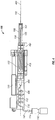
- the rod-style grip, the distributed injection device 100 provides the needle 102, the needle receiving member 108, the therapeutic agent reservoir 110, and the linear drive 120 associated with the housing 118, and the second reservoir 140, and fluid drive 114 external the housing 118 and connected via the reservoir-connecting conduit 142.
- Fig. 4 depicts the rod-style grip of the distributed injection device 100 prior to and at the time of injection, whereby the needle 102 is at its most extended position.
- the alternative embodiment depicted in Figs. 4 and 5 provides for the linear drive 120 to contract, thus repositioning the needle 102 into the needle receiving member 108 best described as retraction of the needle 102.
- Fig. 5 depicts the rod-style grip version of the distributed injection device 100 at then end of use, when the liner drive 120 is fully engaged (retracted) and the needle 102 is fully encapsulated.
- the needle 102 is affixed at its attachment end 104 to a slide member 134 which is repositioned within the needle-receiving member 108. All components in the rod-style grip are aligned with the longitudinal axis 400 of the distributed injection device 100.
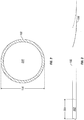
- the therapeutic agent reservoir 110 may be created by a length of narrow tubing as provided above, coiled about a portion of the slide member 134.
- the needle 102 is positioned at one end of the injection device 100 and is connected, preferably by the detachable fitting known in the art, to a slide member 134 having an internal passage 135 therethrough and which is connected to the therapeutic agent reservoir 110, the substantial length of which is coiled about the upper portion of the slide member 134.
- the receiving member 108 may be associated with a guide arm 402 extending from the upper portion 404 of the housing 118 to maintain position and alignment during operation.
- the guide arm 402 may extend a length equal to the stroke of the linear drive 120 to provide the retraction of the needle 102 while maintaining contact with the patient.
- the guide arm 402 may telescope from a passage 406 and may, if desired, be loaded via a spring.
- the linear drive 120 which may be a piston-cylinder assembly, may be positioned opposite the slide member 134 from the guide arm 402 and may extend to drive the receiving member 108 forward and thus retract the needle 102.
- the linear drive 120 moves relative to the needle 102 and therefore apparently in opposition.
- the needle 102 and the therapeutic agent reservoir 110 may be incorporated into a single cartridge unit 600 for ease of installation and removal.
- the tubing 142 from the second reservoir 140 to the therapeutic agent reservoir 110 may include a coiled portion above the slide member 134, constructed to flex during operation of the linear drive 120 when the therapeutic agent reservoir 110, together with the slide member 134 travels downward.
- the cartridge 600 is mounted in a telescoping tube receiver 408 which expands during initial operation of the linear drive 120 incident to retraction of the needle 102 from a body due to the advance of the needle-receiving member 108.
- the telescoping tube receiver 408 houses the end of a conduit 412 which is coiled to absorb the travel of the telescoping tube receiver 408.
- the telescoping tube receiver 408 is secured to the linear actuator via a mount block 410 which advances the telescoping tube receiver 408, causing it to telescopically extend.
- the coiled conduit 412 exits from the top of the telescoping tube receiver 408 and is connected to the conduit 142 from the second reservoir 140.
- a cartridge 600 By locating the non-therapeutic units (second reservoir 140, fluid drive 114 and reservoir-connecting conduit 142) external of the housing 118, which is not necessarily required, these units do not need to be discarded or placed in isolation and can therefore be immediately used thereafter. This may be particularly helpful if the volume of therapeutic reservoir 110 provides less volume of therapeutic agent 116 than needed during an operating session.
- all components can be located within the housing 118 to provide a self-contained device. However, all components will thereafter be subject to post-use restrictions and potential isolation, requiring disposal of the fluid 114 consistent with more stringent requirements.
- the housing 118 and the receiving member 108 may be constructed of or coated with a shielding material to protect the operator from radiation emitted from the needle 102 where the fluid 116 is radioactive.
- receiving member 108 is constructed of tungsten
- the reservoir 110 may also be constructed of or coated with a shielding material to protect the operator in such an instance.
- the components may include a plastic layer or may be composed of plastic.
- a flow meter 126 may be positioned intermediate the second reservoir 110 and the needle 102 and may provide data to a computer 128 to compare with data from a linear positioning sensor 130 to ensure the flow rate from the reservoir 110 is equal to the flow rate associated with the retraction of the needle 102 through the body.
- the housing 118 may include an operating switch 132 which permits the operator to simultaneously activate the linear drive 120 and the fluid drive 114 to ensure the deposition of fluid 116 at the injection end 106 of the needle 102 along the path of needle 102 during retraction.
- the needle 102, the reservoir 110 and any tubing 112 may be removed from the housing 118 for disposal in compliance with safety regulations and the balance of the components not contacting the fluid 116 used again.
- the present invention provides significant advantages over the prior art.
- high pH radioisotopes When high pH radioisotopes are used in treating illness, it is undesirable for the radioisotope to mix with the blood. Rather, it is desirable to deposit the radioisotope along a line in the tissue, particularly along the path of the needle 102 through the body tissue. It appears the high pH radioisotope typically reacts with the tissue, causing coagulation of the microcapillaries and precluding entry of the radioisotope into the bloodstream. Injection of the total volume of the liquid, however, does cause undesirable loss of the radioisotope into the bloodsteam.
- a plurality of injection lines are utilized, as the range of the radioisotope is quite small, often in the range of six (6) millimeters (mm) on each side of the injection line,
- a plurality of injection lines, each corresponding to the needle path therefore, blankets the tumor, with a substantial portion, potentially nearing ninety percent (90%) of the radioisotope remaining in the tumor and being effective there, with only a de minimus portion entering the remainder of the body, in quantities sufficiently low to pose a substantially lower risk of injury that current methods.
Landscapes
- Health & Medical Sciences (AREA)
- Vascular Medicine (AREA)
- Engineering & Computer Science (AREA)
- Anesthesiology (AREA)
- Biomedical Technology (AREA)
- Heart & Thoracic Surgery (AREA)
- Hematology (AREA)
- Life Sciences & Earth Sciences (AREA)
- Animal Behavior & Ethology (AREA)
- General Health & Medical Sciences (AREA)
- Public Health (AREA)
- Veterinary Medicine (AREA)
- Infusion, Injection, And Reservoir Apparatuses (AREA)
Applications Claiming Priority (2)
| Application Number | Priority Date | Filing Date | Title |
|---|---|---|---|
| US13/298,742 US9022987B2 (en) | 2008-07-07 | 2011-11-17 | Delivery system for injection through zone of body |
| PCT/US2012/060818 WO2013074244A1 (en) | 2011-11-17 | 2012-10-18 | Delivery system for injection through zone of body |
Publications (3)
| Publication Number | Publication Date |
|---|---|
| EP2780061A1 EP2780061A1 (en) | 2014-09-24 |
| EP2780061A4 EP2780061A4 (en) | 2015-07-08 |
| EP2780061B1 true EP2780061B1 (en) | 2018-02-21 |
Family
ID=48430033
Family Applications (1)
| Application Number | Title | Priority Date | Filing Date |
|---|---|---|---|
| EP12849893.8A Not-in-force EP2780061B1 (en) | 2011-11-17 | 2012-10-18 | Delivery system for injection through zone of body |
Country Status (6)
| Country | Link |
|---|---|
| US (1) | US9022987B2 (enExample) |
| EP (1) | EP2780061B1 (enExample) |
| JP (1) | JP6057482B2 (enExample) |
| CN (1) | CN104093434B (enExample) |
| CA (1) | CA2856628C (enExample) |
| WO (1) | WO2013074244A1 (enExample) |
Families Citing this family (9)
| Publication number | Priority date | Publication date | Assignee | Title |
|---|---|---|---|---|
| US9808578B2 (en) | 2008-07-07 | 2017-11-07 | Gabriel Institute, Inc. | Delivery system for injections throughout zone of body |
| EP4144390A3 (en) | 2013-06-18 | 2023-07-12 | Enable Injections, Inc. | Vial transfer and injection apparatus and method |
| DE102014005338A1 (de) * | 2014-04-11 | 2015-10-15 | Andreas Gerzen | Injektionsvorrichtung zum kontinuierlichen und gleichmäßigen Applizieren einer Injektionssubstanz |
| US20200023128A1 (en) * | 2016-12-22 | 2020-01-23 | Intervet Inc. | Needleless injector |
| DE102018107100A1 (de) | 2018-03-26 | 2019-09-26 | Henke-Sass, Wolf Gmbh | Vorrichtung zum Applizieren eines Fluids |
| CN110339429A (zh) * | 2019-06-26 | 2019-10-18 | 吴威 | 一种自体胶原脸部填充美容设备及控制方法 |
| CN115955982A (zh) * | 2020-04-21 | 2023-04-11 | 迪帕克.简 | 用于输送治疗药剂的装置和系统 |
| JP7619555B2 (ja) * | 2020-10-02 | 2025-01-22 | 富士フイルム株式会社 | 投与キット |
| US12475987B2 (en) * | 2022-09-20 | 2025-11-18 | Medtronic Navigation, Inc. | Robotically-assisted drug delivery |
Family Cites Families (16)
| Publication number | Priority date | Publication date | Assignee | Title |
|---|---|---|---|---|
| US984037A (en) | 1909-05-11 | 1911-02-14 | John H Sheets | Syringe. |
| GB2080689B (en) | 1980-07-29 | 1984-10-31 | Dent Hugh Robert | Sterilising fitments for injection devices |
| US6056716A (en) | 1987-06-08 | 2000-05-02 | D'antonio Consultants International Inc. | Hypodermic fluid dispenser |
| US5125414A (en) | 1990-01-16 | 1992-06-30 | Dysarz Edward D | Trap in barrel one handed retracted blood sampling device |
| US5338311A (en) | 1993-08-23 | 1994-08-16 | Mahurkar Sakharam D | Hypodermic needle assembly |
| US6478771B1 (en) * | 1998-11-13 | 2002-11-12 | Elan Pharma International Limited | Drug delivery systems and methods |
| US20020068907A1 (en) * | 2000-09-05 | 2002-06-06 | Dysarz Edward D. | Safety syringe with retraction trunk |
| FR2818963B1 (fr) | 2001-01-04 | 2003-04-11 | Valois Sa | Dispositif de distribution de produit fluide du type combidose |
| EP1769811A1 (en) * | 2004-06-21 | 2007-04-04 | Nemoto Kyorindo Co., Ltd. | Medicinal liquid injection system |
| JP2010511414A (ja) | 2005-02-14 | 2010-04-15 | ノボ・ノルデイスク・エー/エス | 医療器具における注入動作 |
| US7645264B2 (en) | 2005-04-11 | 2010-01-12 | Becton, Dickinson And Company | Injection device with secondary reservoir |
| US7462169B2 (en) * | 2007-01-23 | 2008-12-09 | Becton, Dickinson And Company | Safety shield system for an injection pen needle |
| US8529516B2 (en) * | 2008-07-07 | 2013-09-10 | Gabriel Institute, Inc. | Syringe for injection through zone of body |
| AR076719A1 (es) * | 2009-06-02 | 2011-06-29 | Sanofi Aventis Deutschland | Modulo medicinal con derivacion y protector de aguja |
| EP2389969A1 (en) | 2010-05-26 | 2011-11-30 | Omrix Biopharmaceuticals Ltd. | A device for injecting a substance |
| US9579470B2 (en) * | 2010-03-26 | 2017-02-28 | Sanofi-Aventis Deutschland Gmbh | Dedicated needle assembly |
-
2011
- 2011-11-17 US US13/298,742 patent/US9022987B2/en active Active
-
2012
- 2012-10-18 EP EP12849893.8A patent/EP2780061B1/en not_active Not-in-force
- 2012-10-18 WO PCT/US2012/060818 patent/WO2013074244A1/en not_active Ceased
- 2012-10-18 JP JP2014542315A patent/JP6057482B2/ja not_active Expired - Fee Related
- 2012-10-18 CA CA2856628A patent/CA2856628C/en not_active Expired - Fee Related
- 2012-10-18 CN CN201280056482.1A patent/CN104093434B/zh not_active Expired - Fee Related
Non-Patent Citations (1)
| Title |
|---|
| None * |
Also Published As
| Publication number | Publication date |
|---|---|
| CA2856628A1 (en) | 2013-05-23 |
| CN104093434B (zh) | 2016-01-27 |
| US20120065618A1 (en) | 2012-03-15 |
| US9022987B2 (en) | 2015-05-05 |
| WO2013074244A1 (en) | 2013-05-23 |
| JP2014533552A (ja) | 2014-12-15 |
| CN104093434A (zh) | 2014-10-08 |
| EP2780061A1 (en) | 2014-09-24 |
| JP6057482B2 (ja) | 2017-01-11 |
| EP2780061A4 (en) | 2015-07-08 |
| CA2856628C (en) | 2016-07-26 |
Similar Documents
| Publication | Publication Date | Title |
|---|---|---|
| EP2780061B1 (en) | Delivery system for injection through zone of body | |
| EP1385560B1 (en) | Prefillable intradermal delivery device with hidden needle and passive shielding | |
| EP2324875B1 (en) | Hub assembly having a hidden needle for a drug delivery pen | |
| JP3816842B2 (ja) | 別個の薬物リザーバを有する無針ジェット式注入システム | |
| EP2853277B1 (en) | Prefilled safety pen needle | |
| CN100551455C (zh) | 皮内注射器和针头组件 | |
| EP2836257B1 (en) | Injection mechanism utilizing a vial | |
| US10398840B2 (en) | Delivery system for injections throughout zone of body | |
| US8771236B2 (en) | Systems and methods for a medical syringe | |
| US8529516B2 (en) | Syringe for injection through zone of body | |
| EP2777719A2 (en) | Preparation Patch and Safety Syringe System | |
| JP7432096B2 (ja) | 予め充填された安全針と注射器システム | |
| JPH1080487A (ja) | 針収納式使い捨て注射器 |
Legal Events
| Date | Code | Title | Description |
|---|---|---|---|
| PUAI | Public reference made under article 153(3) epc to a published international application that has entered the european phase |
Free format text: ORIGINAL CODE: 0009012 |
|
| 17P | Request for examination filed |
Effective date: 20140429 |
|
| AK | Designated contracting states |
Kind code of ref document: A1 Designated state(s): AL AT BE BG CH CY CZ DE DK EE ES FI FR GB GR HR HU IE IS IT LI LT LU LV MC MK MT NL NO PL PT RO RS SE SI SK SM TR |
|
| DAX | Request for extension of the european patent (deleted) | ||
| RA4 | Supplementary search report drawn up and despatched (corrected) |
Effective date: 20150608 |
|
| RIC1 | Information provided on ipc code assigned before grant |
Ipc: A61M 5/46 20060101ALI20150601BHEP Ipc: A61M 5/32 20060101ALI20150601BHEP Ipc: A61M 5/20 20060101AFI20150601BHEP Ipc: A61M 5/178 20060101ALI20150601BHEP Ipc: A61M 5/48 20060101ALI20150601BHEP Ipc: A61M 5/172 20060101ALI20150601BHEP Ipc: A61M 5/168 20060101ALI20150601BHEP |
|
| GRAP | Despatch of communication of intention to grant a patent |
Free format text: ORIGINAL CODE: EPIDOSNIGR1 |
|
| INTG | Intention to grant announced |
Effective date: 20170906 |
|
| GRAS | Grant fee paid |
Free format text: ORIGINAL CODE: EPIDOSNIGR3 |
|
| GRAA | (expected) grant |
Free format text: ORIGINAL CODE: 0009210 |
|
| AK | Designated contracting states |
Kind code of ref document: B1 Designated state(s): AL AT BE BG CH CY CZ DE DK EE ES FI FR GB GR HR HU IE IS IT LI LT LU LV MC MK MT NL NO PL PT RO RS SE SI SK SM TR |
|
| REG | Reference to a national code |
Ref country code: GB Ref legal event code: FG4D |
|
| REG | Reference to a national code |
Ref country code: CH Ref legal event code: EP |
|
| REG | Reference to a national code |
Ref country code: DE Ref legal event code: R096 Ref document number: 602012043193 Country of ref document: DE Ref country code: AT Ref legal event code: REF Ref document number: 971030 Country of ref document: AT Kind code of ref document: T Effective date: 20180315 |
|
| REG | Reference to a national code |
Ref country code: IE Ref legal event code: FG4D |
|
| REG | Reference to a national code |
Ref country code: NL Ref legal event code: FP |
|
| REG | Reference to a national code |
Ref country code: CH Ref legal event code: NV Representative=s name: MICHELI AND CIE SA, CH |
|
| REG | Reference to a national code |
Ref country code: LT Ref legal event code: MG4D |
|
| REG | Reference to a national code |
Ref country code: AT Ref legal event code: MK05 Ref document number: 971030 Country of ref document: AT Kind code of ref document: T Effective date: 20180221 |
|
| PG25 | Lapsed in a contracting state [announced via postgrant information from national office to epo] |
Ref country code: ES Free format text: LAPSE BECAUSE OF FAILURE TO SUBMIT A TRANSLATION OF THE DESCRIPTION OR TO PAY THE FEE WITHIN THE PRESCRIBED TIME-LIMIT Effective date: 20180221 Ref country code: LT Free format text: LAPSE BECAUSE OF FAILURE TO SUBMIT A TRANSLATION OF THE DESCRIPTION OR TO PAY THE FEE WITHIN THE PRESCRIBED TIME-LIMIT Effective date: 20180221 Ref country code: CY Free format text: LAPSE BECAUSE OF FAILURE TO SUBMIT A TRANSLATION OF THE DESCRIPTION OR TO PAY THE FEE WITHIN THE PRESCRIBED TIME-LIMIT Effective date: 20180221 Ref country code: HR Free format text: LAPSE BECAUSE OF FAILURE TO SUBMIT A TRANSLATION OF THE DESCRIPTION OR TO PAY THE FEE WITHIN THE PRESCRIBED TIME-LIMIT Effective date: 20180221 Ref country code: NO Free format text: LAPSE BECAUSE OF FAILURE TO SUBMIT A TRANSLATION OF THE DESCRIPTION OR TO PAY THE FEE WITHIN THE PRESCRIBED TIME-LIMIT Effective date: 20180521 Ref country code: FI Free format text: LAPSE BECAUSE OF FAILURE TO SUBMIT A TRANSLATION OF THE DESCRIPTION OR TO PAY THE FEE WITHIN THE PRESCRIBED TIME-LIMIT Effective date: 20180221 |
|
| PG25 | Lapsed in a contracting state [announced via postgrant information from national office to epo] |
Ref country code: RS Free format text: LAPSE BECAUSE OF FAILURE TO SUBMIT A TRANSLATION OF THE DESCRIPTION OR TO PAY THE FEE WITHIN THE PRESCRIBED TIME-LIMIT Effective date: 20180221 Ref country code: AT Free format text: LAPSE BECAUSE OF FAILURE TO SUBMIT A TRANSLATION OF THE DESCRIPTION OR TO PAY THE FEE WITHIN THE PRESCRIBED TIME-LIMIT Effective date: 20180221 Ref country code: GR Free format text: LAPSE BECAUSE OF FAILURE TO SUBMIT A TRANSLATION OF THE DESCRIPTION OR TO PAY THE FEE WITHIN THE PRESCRIBED TIME-LIMIT Effective date: 20180522 Ref country code: BG Free format text: LAPSE BECAUSE OF FAILURE TO SUBMIT A TRANSLATION OF THE DESCRIPTION OR TO PAY THE FEE WITHIN THE PRESCRIBED TIME-LIMIT Effective date: 20180521 Ref country code: LV Free format text: LAPSE BECAUSE OF FAILURE TO SUBMIT A TRANSLATION OF THE DESCRIPTION OR TO PAY THE FEE WITHIN THE PRESCRIBED TIME-LIMIT Effective date: 20180221 Ref country code: SE Free format text: LAPSE BECAUSE OF FAILURE TO SUBMIT A TRANSLATION OF THE DESCRIPTION OR TO PAY THE FEE WITHIN THE PRESCRIBED TIME-LIMIT Effective date: 20180221 |
|
| REG | Reference to a national code |
Ref country code: FR Ref legal event code: PLFP Year of fee payment: 7 |
|
| PG25 | Lapsed in a contracting state [announced via postgrant information from national office to epo] |
Ref country code: RO Free format text: LAPSE BECAUSE OF FAILURE TO SUBMIT A TRANSLATION OF THE DESCRIPTION OR TO PAY THE FEE WITHIN THE PRESCRIBED TIME-LIMIT Effective date: 20180221 Ref country code: PL Free format text: LAPSE BECAUSE OF FAILURE TO SUBMIT A TRANSLATION OF THE DESCRIPTION OR TO PAY THE FEE WITHIN THE PRESCRIBED TIME-LIMIT Effective date: 20180221 Ref country code: AL Free format text: LAPSE BECAUSE OF FAILURE TO SUBMIT A TRANSLATION OF THE DESCRIPTION OR TO PAY THE FEE WITHIN THE PRESCRIBED TIME-LIMIT Effective date: 20180221 Ref country code: EE Free format text: LAPSE BECAUSE OF FAILURE TO SUBMIT A TRANSLATION OF THE DESCRIPTION OR TO PAY THE FEE WITHIN THE PRESCRIBED TIME-LIMIT Effective date: 20180221 Ref country code: IT Free format text: LAPSE BECAUSE OF FAILURE TO SUBMIT A TRANSLATION OF THE DESCRIPTION OR TO PAY THE FEE WITHIN THE PRESCRIBED TIME-LIMIT Effective date: 20180221 |
|
| REG | Reference to a national code |
Ref country code: DE Ref legal event code: R097 Ref document number: 602012043193 Country of ref document: DE |
|
| PG25 | Lapsed in a contracting state [announced via postgrant information from national office to epo] |
Ref country code: DK Free format text: LAPSE BECAUSE OF FAILURE TO SUBMIT A TRANSLATION OF THE DESCRIPTION OR TO PAY THE FEE WITHIN THE PRESCRIBED TIME-LIMIT Effective date: 20180221 Ref country code: SM Free format text: LAPSE BECAUSE OF FAILURE TO SUBMIT A TRANSLATION OF THE DESCRIPTION OR TO PAY THE FEE WITHIN THE PRESCRIBED TIME-LIMIT Effective date: 20180221 Ref country code: SK Free format text: LAPSE BECAUSE OF FAILURE TO SUBMIT A TRANSLATION OF THE DESCRIPTION OR TO PAY THE FEE WITHIN THE PRESCRIBED TIME-LIMIT Effective date: 20180221 Ref country code: CZ Free format text: LAPSE BECAUSE OF FAILURE TO SUBMIT A TRANSLATION OF THE DESCRIPTION OR TO PAY THE FEE WITHIN THE PRESCRIBED TIME-LIMIT Effective date: 20180221 |
|
| PLBE | No opposition filed within time limit |
Free format text: ORIGINAL CODE: 0009261 |
|
| STAA | Information on the status of an ep patent application or granted ep patent |
Free format text: STATUS: NO OPPOSITION FILED WITHIN TIME LIMIT |
|
| 26N | No opposition filed |
Effective date: 20181122 |
|
| PG25 | Lapsed in a contracting state [announced via postgrant information from national office to epo] |
Ref country code: SI Free format text: LAPSE BECAUSE OF FAILURE TO SUBMIT A TRANSLATION OF THE DESCRIPTION OR TO PAY THE FEE WITHIN THE PRESCRIBED TIME-LIMIT Effective date: 20180221 |
|
| REG | Reference to a national code |
Ref country code: BE Ref legal event code: MM Effective date: 20181031 |
|
| PG25 | Lapsed in a contracting state [announced via postgrant information from national office to epo] |
Ref country code: MC Free format text: LAPSE BECAUSE OF FAILURE TO SUBMIT A TRANSLATION OF THE DESCRIPTION OR TO PAY THE FEE WITHIN THE PRESCRIBED TIME-LIMIT Effective date: 20180221 Ref country code: LU Free format text: LAPSE BECAUSE OF NON-PAYMENT OF DUE FEES Effective date: 20181018 |
|
| PG25 | Lapsed in a contracting state [announced via postgrant information from national office to epo] |
Ref country code: BE Free format text: LAPSE BECAUSE OF NON-PAYMENT OF DUE FEES Effective date: 20181031 |
|
| PG25 | Lapsed in a contracting state [announced via postgrant information from national office to epo] |
Ref country code: MT Free format text: LAPSE BECAUSE OF NON-PAYMENT OF DUE FEES Effective date: 20181018 |
|
| PGFP | Annual fee paid to national office [announced via postgrant information from national office to epo] |
Ref country code: IE Payment date: 20191015 Year of fee payment: 8 Ref country code: DE Payment date: 20191021 Year of fee payment: 8 Ref country code: NL Payment date: 20191015 Year of fee payment: 8 |
|
| PGFP | Annual fee paid to national office [announced via postgrant information from national office to epo] |
Ref country code: FR Payment date: 20191015 Year of fee payment: 8 |
|
| PG25 | Lapsed in a contracting state [announced via postgrant information from national office to epo] |
Ref country code: TR Free format text: LAPSE BECAUSE OF FAILURE TO SUBMIT A TRANSLATION OF THE DESCRIPTION OR TO PAY THE FEE WITHIN THE PRESCRIBED TIME-LIMIT Effective date: 20180221 |
|
| PGFP | Annual fee paid to national office [announced via postgrant information from national office to epo] |
Ref country code: CH Payment date: 20191031 Year of fee payment: 8 |
|
| PGFP | Annual fee paid to national office [announced via postgrant information from national office to epo] |
Ref country code: GB Payment date: 20191016 Year of fee payment: 8 |
|
| PG25 | Lapsed in a contracting state [announced via postgrant information from national office to epo] |
Ref country code: PT Free format text: LAPSE BECAUSE OF FAILURE TO SUBMIT A TRANSLATION OF THE DESCRIPTION OR TO PAY THE FEE WITHIN THE PRESCRIBED TIME-LIMIT Effective date: 20180221 |
|
| PG25 | Lapsed in a contracting state [announced via postgrant information from national office to epo] |
Ref country code: HU Free format text: LAPSE BECAUSE OF FAILURE TO SUBMIT A TRANSLATION OF THE DESCRIPTION OR TO PAY THE FEE WITHIN THE PRESCRIBED TIME-LIMIT; INVALID AB INITIO Effective date: 20121018 Ref country code: MK Free format text: LAPSE BECAUSE OF NON-PAYMENT OF DUE FEES Effective date: 20180221 |
|
| PG25 | Lapsed in a contracting state [announced via postgrant information from national office to epo] |
Ref country code: IS Free format text: LAPSE BECAUSE OF FAILURE TO SUBMIT A TRANSLATION OF THE DESCRIPTION OR TO PAY THE FEE WITHIN THE PRESCRIBED TIME-LIMIT Effective date: 20180621 |
|
| REG | Reference to a national code |
Ref country code: DE Ref legal event code: R119 Ref document number: 602012043193 Country of ref document: DE |
|
| REG | Reference to a national code |
Ref country code: CH Ref legal event code: PL |
|
| REG | Reference to a national code |
Ref country code: NL Ref legal event code: MM Effective date: 20201101 |
|
| GBPC | Gb: european patent ceased through non-payment of renewal fee |
Effective date: 20201018 |
|
| PG25 | Lapsed in a contracting state [announced via postgrant information from national office to epo] |
Ref country code: NL Free format text: LAPSE BECAUSE OF NON-PAYMENT OF DUE FEES Effective date: 20201101 Ref country code: DE Free format text: LAPSE BECAUSE OF NON-PAYMENT OF DUE FEES Effective date: 20210501 Ref country code: FR Free format text: LAPSE BECAUSE OF NON-PAYMENT OF DUE FEES Effective date: 20201031 |
|
| PG25 | Lapsed in a contracting state [announced via postgrant information from national office to epo] |
Ref country code: LI Free format text: LAPSE BECAUSE OF NON-PAYMENT OF DUE FEES Effective date: 20201031 Ref country code: GB Free format text: LAPSE BECAUSE OF NON-PAYMENT OF DUE FEES Effective date: 20201018 Ref country code: CH Free format text: LAPSE BECAUSE OF NON-PAYMENT OF DUE FEES Effective date: 20201031 |
|
| PG25 | Lapsed in a contracting state [announced via postgrant information from national office to epo] |
Ref country code: IE Free format text: LAPSE BECAUSE OF NON-PAYMENT OF DUE FEES Effective date: 20201018 |