EP2779907B1 - Medical measuring system and method - Google Patents
Medical measuring system and method Download PDFInfo
- Publication number
- EP2779907B1 EP2779907B1 EP12849119.8A EP12849119A EP2779907B1 EP 2779907 B1 EP2779907 B1 EP 2779907B1 EP 12849119 A EP12849119 A EP 12849119A EP 2779907 B1 EP2779907 B1 EP 2779907B1
- Authority
- EP
- European Patent Office
- Prior art keywords
- medical
- bedside controller
- measurement
- touch
- user
- Prior art date
- Legal status (The legal status is an assumption and is not a legal conclusion. Google has not performed a legal analysis and makes no representation as to the accuracy of the status listed.)
- Active
Links
Images




Classifications
-
- A—HUMAN NECESSITIES
- A61—MEDICAL OR VETERINARY SCIENCE; HYGIENE
- A61B—DIAGNOSIS; SURGERY; IDENTIFICATION
- A61B5/00—Measuring for diagnostic purposes; Identification of persons
- A61B5/0059—Measuring for diagnostic purposes; Identification of persons using light, e.g. diagnosis by transillumination, diascopy, fluorescence
- A61B5/0082—Measuring for diagnostic purposes; Identification of persons using light, e.g. diagnosis by transillumination, diascopy, fluorescence adapted for particular medical purposes
- A61B5/0084—Measuring for diagnostic purposes; Identification of persons using light, e.g. diagnosis by transillumination, diascopy, fluorescence adapted for particular medical purposes for introduction into the body, e.g. by catheters
-
- A—HUMAN NECESSITIES
- A61—MEDICAL OR VETERINARY SCIENCE; HYGIENE
- A61B—DIAGNOSIS; SURGERY; IDENTIFICATION
- A61B5/00—Measuring for diagnostic purposes; Identification of persons
- A61B5/0059—Measuring for diagnostic purposes; Identification of persons using light, e.g. diagnosis by transillumination, diascopy, fluorescence
-
- A—HUMAN NECESSITIES
- A61—MEDICAL OR VETERINARY SCIENCE; HYGIENE
- A61B—DIAGNOSIS; SURGERY; IDENTIFICATION
- A61B5/00—Measuring for diagnostic purposes; Identification of persons
- A61B5/0059—Measuring for diagnostic purposes; Identification of persons using light, e.g. diagnosis by transillumination, diascopy, fluorescence
- A61B5/0062—Arrangements for scanning
- A61B5/0066—Optical coherence imaging
-
- A—HUMAN NECESSITIES
- A61—MEDICAL OR VETERINARY SCIENCE; HYGIENE
- A61B—DIAGNOSIS; SURGERY; IDENTIFICATION
- A61B5/00—Measuring for diagnostic purposes; Identification of persons
- A61B5/0059—Measuring for diagnostic purposes; Identification of persons using light, e.g. diagnosis by transillumination, diascopy, fluorescence
- A61B5/0077—Devices for viewing the surface of the body, e.g. camera, magnifying lens
-
- A—HUMAN NECESSITIES
- A61—MEDICAL OR VETERINARY SCIENCE; HYGIENE
- A61B—DIAGNOSIS; SURGERY; IDENTIFICATION
- A61B5/00—Measuring for diagnostic purposes; Identification of persons
- A61B5/74—Details of notification to user or communication with user or patient; User input means
- A61B5/742—Details of notification to user or communication with user or patient; User input means using visual displays
- A61B5/7435—Displaying user selection data, e.g. icons in a graphical user interface
-
- A—HUMAN NECESSITIES
- A61—MEDICAL OR VETERINARY SCIENCE; HYGIENE
- A61B—DIAGNOSIS; SURGERY; IDENTIFICATION
- A61B5/00—Measuring for diagnostic purposes; Identification of persons
- A61B5/74—Details of notification to user or communication with user or patient; User input means
- A61B5/742—Details of notification to user or communication with user or patient; User input means using visual displays
- A61B5/7445—Display arrangements, e.g. multiple display units
-
- A—HUMAN NECESSITIES
- A61—MEDICAL OR VETERINARY SCIENCE; HYGIENE
- A61B—DIAGNOSIS; SURGERY; IDENTIFICATION
- A61B6/00—Apparatus or devices for radiation diagnosis; Apparatus or devices for radiation diagnosis combined with radiation therapy equipment
- A61B6/50—Apparatus or devices for radiation diagnosis; Apparatus or devices for radiation diagnosis combined with radiation therapy equipment specially adapted for specific body parts; specially adapted for specific clinical applications
- A61B6/504—Apparatus or devices for radiation diagnosis; Apparatus or devices for radiation diagnosis combined with radiation therapy equipment specially adapted for specific body parts; specially adapted for specific clinical applications for diagnosis of blood vessels, e.g. by angiography
-
- A—HUMAN NECESSITIES
- A61—MEDICAL OR VETERINARY SCIENCE; HYGIENE
- A61B—DIAGNOSIS; SURGERY; IDENTIFICATION
- A61B8/00—Diagnosis using ultrasonic, sonic or infrasonic waves
- A61B8/12—Diagnosis using ultrasonic, sonic or infrasonic waves in body cavities or body tracts, e.g. by using catheters
-
- A—HUMAN NECESSITIES
- A61—MEDICAL OR VETERINARY SCIENCE; HYGIENE
- A61B—DIAGNOSIS; SURGERY; IDENTIFICATION
- A61B8/00—Diagnosis using ultrasonic, sonic or infrasonic waves
- A61B8/44—Constructional features of the ultrasonic, sonic or infrasonic diagnostic device
- A61B8/4416—Constructional features of the ultrasonic, sonic or infrasonic diagnostic device related to combined acquisition of different diagnostic modalities, e.g. combination of ultrasound and X-ray acquisitions
-
- A—HUMAN NECESSITIES
- A61—MEDICAL OR VETERINARY SCIENCE; HYGIENE
- A61M—DEVICES FOR INTRODUCING MEDIA INTO, OR ONTO, THE BODY; DEVICES FOR TRANSDUCING BODY MEDIA OR FOR TAKING MEDIA FROM THE BODY; DEVICES FOR PRODUCING OR ENDING SLEEP OR STUPOR
- A61M5/00—Devices for bringing media into the body in a subcutaneous, intra-vascular or intramuscular way; Accessories therefor, e.g. filling or cleaning devices, arm-rests
- A61M5/007—Devices for bringing media into the body in a subcutaneous, intra-vascular or intramuscular way; Accessories therefor, e.g. filling or cleaning devices, arm-rests for contrast media
-
- G—PHYSICS
- G06—COMPUTING OR CALCULATING; COUNTING
- G06F—ELECTRIC DIGITAL DATA PROCESSING
- G06F3/00—Input arrangements for transferring data to be processed into a form capable of being handled by the computer; Output arrangements for transferring data from processing unit to output unit, e.g. interface arrangements
- G06F3/01—Input arrangements or combined input and output arrangements for interaction between user and computer
-
- G—PHYSICS
- G06—COMPUTING OR CALCULATING; COUNTING
- G06F—ELECTRIC DIGITAL DATA PROCESSING
- G06F3/00—Input arrangements for transferring data to be processed into a form capable of being handled by the computer; Output arrangements for transferring data from processing unit to output unit, e.g. interface arrangements
- G06F3/01—Input arrangements or combined input and output arrangements for interaction between user and computer
- G06F3/03—Arrangements for converting the position or the displacement of a member into a coded form
- G06F3/041—Digitisers, e.g. for touch screens or touch pads, characterised by the transducing means
-
- G—PHYSICS
- G06—COMPUTING OR CALCULATING; COUNTING
- G06F—ELECTRIC DIGITAL DATA PROCESSING
- G06F3/00—Input arrangements for transferring data to be processed into a form capable of being handled by the computer; Output arrangements for transferring data from processing unit to output unit, e.g. interface arrangements
- G06F3/01—Input arrangements or combined input and output arrangements for interaction between user and computer
- G06F3/048—Interaction techniques based on graphical user interfaces [GUI]
- G06F3/0487—Interaction techniques based on graphical user interfaces [GUI] using specific features provided by the input device, e.g. functions controlled by the rotation of a mouse with dual sensing arrangements, or of the nature of the input device, e.g. tap gestures based on pressure sensed by a digitiser
- G06F3/0488—Interaction techniques based on graphical user interfaces [GUI] using specific features provided by the input device, e.g. functions controlled by the rotation of a mouse with dual sensing arrangements, or of the nature of the input device, e.g. tap gestures based on pressure sensed by a digitiser using a touch-screen or digitiser, e.g. input of commands through traced gestures
- G06F3/04883—Interaction techniques based on graphical user interfaces [GUI] using specific features provided by the input device, e.g. functions controlled by the rotation of a mouse with dual sensing arrangements, or of the nature of the input device, e.g. tap gestures based on pressure sensed by a digitiser using a touch-screen or digitiser, e.g. input of commands through traced gestures for inputting data by handwriting, e.g. gesture or text
-
- G—PHYSICS
- G16—INFORMATION AND COMMUNICATION TECHNOLOGY [ICT] SPECIALLY ADAPTED FOR SPECIFIC APPLICATION FIELDS
- G16H—HEALTHCARE INFORMATICS, i.e. INFORMATION AND COMMUNICATION TECHNOLOGY [ICT] SPECIALLY ADAPTED FOR THE HANDLING OR PROCESSING OF MEDICAL OR HEALTHCARE DATA
- G16H40/00—ICT specially adapted for the management or administration of healthcare resources or facilities; ICT specially adapted for the management or operation of medical equipment or devices
- G16H40/60—ICT specially adapted for the management or administration of healthcare resources or facilities; ICT specially adapted for the management or operation of medical equipment or devices for the operation of medical equipment or devices
- G16H40/63—ICT specially adapted for the management or administration of healthcare resources or facilities; ICT specially adapted for the management or operation of medical equipment or devices for the operation of medical equipment or devices for local operation
-
- A—HUMAN NECESSITIES
- A61—MEDICAL OR VETERINARY SCIENCE; HYGIENE
- A61B—DIAGNOSIS; SURGERY; IDENTIFICATION
- A61B2560/00—Constructional details of operational features of apparatus; Accessories for medical measuring apparatus
- A61B2560/04—Constructional details of apparatus
- A61B2560/0437—Trolley or cart-type apparatus
-
- A—HUMAN NECESSITIES
- A61—MEDICAL OR VETERINARY SCIENCE; HYGIENE
- A61B—DIAGNOSIS; SURGERY; IDENTIFICATION
- A61B2560/00—Constructional details of operational features of apparatus; Accessories for medical measuring apparatus
- A61B2560/04—Constructional details of apparatus
- A61B2560/0487—Special user inputs or interfaces
-
- A—HUMAN NECESSITIES
- A61—MEDICAL OR VETERINARY SCIENCE; HYGIENE
- A61B—DIAGNOSIS; SURGERY; IDENTIFICATION
- A61B5/00—Measuring for diagnostic purposes; Identification of persons
- A61B5/0002—Remote monitoring of patients using telemetry, e.g. transmission of vital signals via a communication network
- A61B5/0004—Remote monitoring of patients using telemetry, e.g. transmission of vital signals via a communication network characterised by the type of physiological signal transmitted
- A61B5/0013—Medical image data
-
- A—HUMAN NECESSITIES
- A61—MEDICAL OR VETERINARY SCIENCE; HYGIENE
- A61B—DIAGNOSIS; SURGERY; IDENTIFICATION
- A61B5/00—Measuring for diagnostic purposes; Identification of persons
- A61B5/0093—Detecting, measuring or recording by applying one single type of energy and measuring its conversion into another type of energy
- A61B5/0095—Detecting, measuring or recording by applying one single type of energy and measuring its conversion into another type of energy by applying light and detecting acoustic waves, i.e. photoacoustic measurements
-
- A—HUMAN NECESSITIES
- A61—MEDICAL OR VETERINARY SCIENCE; HYGIENE
- A61B—DIAGNOSIS; SURGERY; IDENTIFICATION
- A61B5/00—Measuring for diagnostic purposes; Identification of persons
- A61B5/103—Measuring devices for testing the shape, pattern, colour, size or movement of the body or parts thereof, for diagnostic purposes
- A61B5/107—Measuring physical dimensions, e.g. size of the entire body or parts thereof
- A61B5/1076—Measuring physical dimensions, e.g. size of the entire body or parts thereof for measuring dimensions inside body cavities, e.g. using catheters
-
- A—HUMAN NECESSITIES
- A61—MEDICAL OR VETERINARY SCIENCE; HYGIENE
- A61B—DIAGNOSIS; SURGERY; IDENTIFICATION
- A61B6/00—Apparatus or devices for radiation diagnosis; Apparatus or devices for radiation diagnosis combined with radiation therapy equipment
- A61B6/56—Details of data transmission or power supply, e.g. use of slip rings
-
- A—HUMAN NECESSITIES
- A61—MEDICAL OR VETERINARY SCIENCE; HYGIENE
- A61B—DIAGNOSIS; SURGERY; IDENTIFICATION
- A61B8/00—Diagnosis using ultrasonic, sonic or infrasonic waves
- A61B8/46—Ultrasonic, sonic or infrasonic diagnostic devices with special arrangements for interfacing with the operator or the patient
- A61B8/467—Ultrasonic, sonic or infrasonic diagnostic devices with special arrangements for interfacing with the operator or the patient characterised by special input means
-
- A—HUMAN NECESSITIES
- A61—MEDICAL OR VETERINARY SCIENCE; HYGIENE
- A61B—DIAGNOSIS; SURGERY; IDENTIFICATION
- A61B8/00—Diagnosis using ultrasonic, sonic or infrasonic waves
- A61B8/56—Details of data transmission or power supply
-
- A—HUMAN NECESSITIES
- A61—MEDICAL OR VETERINARY SCIENCE; HYGIENE
- A61B—DIAGNOSIS; SURGERY; IDENTIFICATION
- A61B8/00—Diagnosis using ultrasonic, sonic or infrasonic waves
- A61B8/56—Details of data transmission or power supply
- A61B8/565—Details of data transmission or power supply involving data transmission via a network
Definitions
- Embodiments of the present disclosure relate generally to the field of medical devices and, more particularly, to a medical measuring system and associated methods of use.
- IVUS intravascular ultrasound
- FL-IVUS forward looking IVUS
- FFR fractional flow reserve
- CFR coronary flow reserve
- OCT optical coherence tomography
- trans-esophageal echocardiography and image-guided therapy.
- image-guided therapy many of these procedures are carried out by a multitude of physicians and clinicians, where each performs an assigned task. For example, a physician may stand next to a patient in the sterile field and guide the insertion and pull back of an imaging catheter. A clinician near the physician may control the procedure workflow with a controller, for example by starting and stopping the capture of images.
- a second clinician in an adjacent control room working at a desktop computer may select the images of interest and make measurements on them.
- the physician in the catheter lab must instruct the clinician in the control room on how to make such measurements. This may lengthen the time of the procedure, increase the cost of the procedure, and may lead to measurement errors due to miscommunication or clinician inexperience.
- a clinician may typically have to select a measurement mode prior to making any measurements, reducing the efficiency of the medical sensing workflow.
- US 2005/049509 is directed to a minimally invasive system and method for monitoring changes in a cervix opening during labor, including changes in its diameter.
- the system having a probe and a monitoring unit serve to monitor periodically the cervix opening during labor and obtain measurements of the diameter of the cervix opening.
- the probe primarily includes a camera for imaging the cervix opening, a lens to provide an optimal field of view for the camera at close range to the cervix opening, a light source to illuminate the cervix and a balloon to expand the vagina around the probe and position the probe to allow unobstructed imaging of the cervix.
- the monitoring unit which controls the probe to acquire images of the cervix and receives and processes image data from the probe includes a processor which uses image segmentation techniques to identify and measure the opening of the cervix and generates data signals.
- the monitoring unit also includes an image display which displays information based on the data signals for viewing by health care providers and/or the patient, including graphic images of the cervix opening and other text information relating to the cervix opening as an indicator of the progress of labor.
- the processor implements segmentation techniques and/or blob analysis algorithms to analyze the images of the cervix to identify the opening and measure its diameter. Other algorithms may also be implemented to correct for any spatial distortion, particularly barrel distortion.
- EP 1 381 315 describes a method for analyzing tubular structures in a patient, including steps of: selecting a region of interest and a location within the region of interest from a displayed tube-shaped tree representative of a tubular structure in a patient; identifying a centerline of a structure within the tube-shaped tree within the region of interest; and displaying one or more views of the region of interest.
- the view or views are selected from at least a segmented 3-D view having the region of interest identified, a curved view of the selected branch , a reformatted view dependent upon the identified centerline, and a 3-D view dependent upon the identified centerline.
- EP 1 229 822 describes a parameter evaluation system comprising a boundary input device for setting boundaries in a variation range of one or more parameters, thereby to define regions within said variation range, a label input device for associating labels with said regions, a rule input device for setting rules to associate at least one of a plurality of output recommendations with each of said regions and with combinations thereof and an output device to present a user with an output recommendation associated with a region or combination thereof corresponding to at least one measured parameter input to said system.
- the input device is a parameter value region selection and categorization input device for setting boundaries in the variation range of the parameter, defining regions therebetween and categorizing the regions.
- the device comprises a visual representation of the variation range as a linear continuum, a continuum divider for visually dividing the continuum at user selectable points therealong, the points corresponding to values of the parameter, thereby to define regions therebetween and a category definer for defining categories for association with the regions.
- the device has an application in a patient monitoring kit under remote supervision of a physician.
- the uni-stroke shapes are recognized by support vector machines (SVM).
- SVM support vector machines
- an intermediate feature recognizer is used to recognize shapes of intermediate complexity such as a dashed line, which improves sketch recognition performance in the COA domain.
- the system uses the LADDER shape definition language to represent the geometric properties of shapes, and is capable of recognizing common COA symbols of multi-stroke sketches and gesture commands with a recognition accuracy of more than 98%.
- US 2006/227140 describes methods to provide methods for beautifying sketches. Methods are disclosed for determining segments of drawings that represent geometric primitives and implied geometric constraints. Beautification methods provide for replacement of sketched primitives and over- and under-sketched drawings. After beautification methods provide for checking the initial segmentation of the sketch to determine whether false segmentation points were identified. Methods are also disclosed to provide for searching of drawings based upon a beautified sketch. User interactivity is provided to further refine search results.
- US 2004/040091 describes a holding device for medical instruments at a patient's bed, which are accommodated in suspension components.
- Holding devices for various medical instruments such as respirators and accessories, infusion and secretion bags, measuring instruments and disposable articles, are used at patients' beds in many areas.
- a frequent drawback of prior-art holding devices is that the support at the patient's bed is unstable because the holding devices are suspended only loosely in a rail or handle.
- the holding device according to the present invention guarantees stable fastening at the patient's bed. It comprises a horizontal crossbeam, which is fixed on the sides of a peripheral strap at the foot end of the patient's bed via, e.g., fixing means designed as metal claws.
- Two vertical suspension carriers with openings for receiving suspension components have suspension sections at their upper ends for suspension on the straps. It would also be possible to suspend the suspension sections on a wall rail or cabinet rail.
- the present application describes a method of performing measurements on medical images with a bedside controller.
- the method includes receiving, through a touch-sensitive display on the bedside controller, a user measurement input on an image displayed on the display, the user measurement input including a start point defined by a point of initial contact with the touch-sensitive display and an end point defined by a point of last contact with the touch-sensitive display.
- the method also includes selecting a measurement mode based on a shape of the user measurement input and calculating a measurement value associated with the user measurement input based on the measurement mode.
- the method of performing measurements may include selecting one of a diameter measurement mode and an area measurement mode based on the shape of the user measurement input.
- the present application describes a bedside controller.
- the bedside controller includes a housing, the housing including self-contained mounting structure, a touch-sensitive display disposed within a surface of the housing and configured to display images and receive user input on the surface, a processor disposed within the housing, and a communication module disposed within the housing, communicatively coupled to the processor, and configured to transmit and receive medical data from a processing system.
- the bedside controller also includes a non-transitory computer readable storage module disposed within the housing, communicatively coupled to the processor, and including a plurality of instructions stored therein and executable by the processor.
- the plurality of instructions include instructions for receiving, through the touch-sensitive display, a user measurement input on an image displayed on the display, instructions for selecting a measurement mode based on a shape of the user measurement input, and instructions for calculating a measurement value associated with the user measurement input based on the measurement mode.
- the present disclosure is directed to a medical measuring system.
- the medical procedure workflow system includes a medical sensor device configured to gather medical data from a patient and a processing system communicatively coupled to the medical sensor device and operable to receive the medical data from the medical sensor device, the processing system being further operable to transform the medical data into medical images representative of the patient.
- the system also includes a bedside controller communicatively coupled to the processing system and operable to receive the medical images from the processing system and display the medical images on a touch-sensitive display, the bedside controller being further configured to receive, through the touch-sensitive display, a user measurement input on a medical image displayed on the display, select a measurement mode based on a shape of the user measurement input, and calculate a measurement value associated with the user measurement input based on the measurement mode.
- a bedside controller communicatively coupled to the processing system and operable to receive the medical images from the processing system and display the medical images on a touch-sensitive display, the bedside controller being further configured to receive, through the touch-sensitive display, a user measurement input on a medical image displayed on the display, select a measurement mode based on a shape of the user measurement input, and calculate a measurement value associated with the user measurement input based on the measurement mode.
- the bedside controller may be configured to receive the user measurement input while in a sterile field surrounding the patient. Additionally, the bedside controller may be configured to select one of a diameter measurement mode and an area measurement mode based on the shape of the user measurement input.
- the present application describes a method of conducting a medical workflow with a touch-sensitive bedside controller.
- the method includes initiating a medical workflow using a graphical user interface on the bedside controller, positioning an imaging tool within a patient's body based on images captured by the imaging tools and displayed on the bedside controller, controlling the commencement and termination of a recordation of images captured by the imaging tool using the graphical user interface on the bedside controller, navigating through the recorded images to identify an image of interest using the graphical user interface on the bedside controller, and performing measurements on the image of interest using the graphical user interface on the bedside controller.
- the performing measurements may include touching and releasing portions of the image of interest as it is displayed on the bedside controller to make one of an area measurement and a diameter measurement.
- the present application describes a bedside controller.
- the bedside controller include a housing, a touch-sensitive display disposed within a surface of the housing and configured to display images and receive user input on the surface, and a processor disposed within the housing.
- the bedside controller also includes a communication module disposed within the housing, communicatively coupled to the processor, and configured to transmit and receive medical data and a non-transitory computer readable storage module disposed within the housing, communicatively coupled to the processor, and including a plurality of instructions stored therein and executable by the processor.
- the plurality of instructions include instructions for rendering a graphical user interface (GUI) on the touch-sensitive display, instructions for displaying images of a patient as they are being captured by an imaging tool disposed within the patient's body, and instructions for initiating and terminating a recordation of the images based on user input to the GUI.
- the plurality of instructions also include instructions for displaying the recorded images within the GUI so that a user may identify an image of interest and instructions for making a measurement on the image of interest based on a user measurement input to the GUI.
- the present application describes a bedside controller.
- the bedside controller includes an integrally formed housing and self-contained mounting structure disposed on the housing.
- the mounting structure includes a mounting channel defined in the housing and a retaining clamp disposed above the mounting channel and configured to releasably secure a mounting platform within the mounting channel such that the bedside controller is mounted to the mounting platform.
- the bedside controller also includes a touch-sensitive display disposed within a surface of the housing and configured to display images and receive user input on the surface, a processor disposed within the housing, a communication module disposed within the housing, communicatively coupled to the processor, and configured to transmit and receive medical data, and a battery disposed within the integrally formed housing and electrically coupled to the touch-sensitive display, the processor, and the communication module.
- the self-contained mounting structure may be configured to releasably secure the bedside controller to the bed rail in such a manner that the display of the bedside controller is generally parallel with a top surface of a table associated with the bed rail.
- the present application describes a method of releasably mounting a bedside controller to a mounting platform associated with a patient undergoing an intravascular workflow.
- the method includes pivoting a retaining clamp to an open position, the retaining clamp being disposed on the bedside controller such that it extends over a mounting channel defined in a housing of the bedside controller, positioning the bedside controller such that the mounting platform extends through the mounting channel, and releasing the retaining clamp such that it engages the mounting platform to releasably secure the mounting platform within the mounting channel, thereby mounting the bedside controller to the mounting platform.
- the method also includes viewing intravascular medical information associated with the patient displayed on a touch-sensitive display of the bedside controller and inputting user inputs on the touch-sensitive display to manipulate the medical information displayed on the touch-sensitive display.
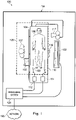
- FIG. 1 is a schematic drawing depicting a medical sensing system 100 including a bedside controller 102 according to one embodiment of the present disclosure.
- the medical sensing system 100 provides for coherent integration and consolidation of multiple forms of acquisition and processing elements designed to be sensitive to a variety of methods used to acquire and interpret human biological physiology and morphological information.
- the bedside controller 102 is a touch-enabled, integrated computing device for the acquisition, control, interpretation, measurement, and display of multi-modality medical sensing data.
- the bedside controller 102 is a tablet-style touch-sensitive computer that provides user controls and diagnostic images on a single surface.
- the bedside controller 102 is operable to present workflow control options and patient image data via graphical user interfaces (GUIs) corresponding to a plurality of medical sensing modalities.
- GUIs graphical user interfaces
- the bedside controller 102 will be described in greater detail in association with Figures 3A , 3B , and 4 .
- the medical sensing system 100 is deployed in a catheter lab 104.
- the catheter lab 104 may be used to perform on a patient 106 any number of medical sensing procedures alone or in combination such as, by way of example and not limitation, angiography, intravascular ultrasound (IVUS), virtual histology (VH), forward looking IVUS (FL-IVUS), intravascular photoacoustic (IVPA) imaging, fractional flow reserve (FFR) determination, coronary flow reserve (CFR) determination, optical coherence tomography (OCT), computed tomography, intracardiac echocardiography (ICE), forward-looking ICE (FLICE), intravascular palpography, transesophageal ultrasound, or any other medical sensing modalities known in the art.
- IVUS intravascular ultrasound
- VH virtual histology
- FL-IVUS forward looking IVUS
- IVPA intravascular photoacoustic
- FFR fractional flow reserve
- CFR coronary flow reserve
- OCT optical coherence tomography
- computed tomography intra
- the bedside controller may be used to cooperate with and control medical treatment systems such as, for example but without limitation, those used for stent placement, coil embolism, ablation therapy, kidney stone treatments, basket placement in a cystoscopy, tumor removal, and chemical therapies.
- the catheter lab 104 further includes a sterile field 105 that encompasses the portions of the catheter lab surrounding the patient 106 on a procedure table 109 and a clinician 107, who may perform any number of medical sensing procedures or treatments.
- the bedside controller 102 may be positioned within the sterile field 105 and may be utilized by the clinician 107 to control a workflow of a medical sensing procedure or treatment being performed on the patient 106.
- the clinician 107 may initiate the procedure workflow, watch real-time IVUS images captured during the procedure, and make measurements on the IVUS images all using the bedside controller 102 inside of the sterile field 105.
- the bedside controller 102 may be utilized outside of the sterile field 105, for instance, in other locations within the catheter lab 104 or in a control room adjacent to the catheter lab. A method of utilizing the bedside controller 102 to control a medical sensing workflow or treatment workflow will be discussed in greater detail in association with Figures 7 and 8 .
- the medical sensing system 100 additionally includes a number of interconnected medical sensing-related tools in the catheter lab 104 to facilitate a multi-modality workflow procedure, such as an IVUS catheter 108, an IVUS patient isolation module (PIM) 112, an OCT catheter 110, and OCT PIM 114, an electrocardiogram (ECG) device 116, an angiogram system 117, a boom display 122, and a multi-modality processing system 124.
- the bedside controller 102, PIMs 112 and 114, ECG device 116, angiography system 117, and boom display 122 are communicatively coupled to the processing system 124.
- the processing system 124 is a computer workstation with the hardware and software to acquire, process, and display multi-modality medical sensing data, but in other embodiments, the processing system may be any other type of computing system operable to process medical sensing data.
- the processing system 124 is operable to accept raw IVUS data from the IVUS PIM 112, transform it into IVUS images, and make the images available to the bedside controller 124, so that they may be displayed to the clinician 107 for analysis.
- the processing system 124 is a computer workstation
- the system includes at least a processor such as a microcontroller or a dedicated central processing unit (CPU), a non-transitory computer-readable storage medium such as a hard drive, random access memory (RAM), and/or compact disk read only memory (CD-ROM), a video controller such as a graphics processing unit (GPU), and a network communication device such as an Ethernet controller.
- the multi-modality processing system 124 is communicatively coupled to a data network 125.
- the data network 125 is a TCP/IP-based local area network (LAN), however in other embodiments, it may utilize a different protocol such as Synchronous Optical Networking (SONET), or may be a wide area network (WAN).
- SONET Synchronous Optical Networking
- the processing system 124 may connect to various resources via the network 125, such as a Digital Imaging and Communications in Medicine (DICOM) system, a Picture Archiving and Communication System (PACS), and a Hospital Information System.
- DICOM Digital Imaging and Communications in Medicine
- PES Picture Archiving and Communication System
- Hospital Information System U.S. Patent Application No. 61/473,570, entitled “MULTI-MODALITY MEDICAL SENSING SYSTEM AND METHOD” and filed on April 8, 2011 , discloses a multi-modality processing system that processes medical sensing data.
- the IVUS PIM 112 and OCT PIM 114 are operable to respectively receive medical sensing data collected from the patient 106 by the IVUS catheter 108 and OCT catheter 110 and are operable to transmit the received data to the processing system 124.
- the IVUS PIM 112 and OCT PIM 114 transmit the medical sensing data over a Peripheral Component Interconnect Express (PCIe) data bus connection, but, in other embodiments, they may transmit data over a USB connection, a Thunderbolt connection, a FireWire connection, or some other high-speed data bus connection.
- the ECG device 116 is operable to transmit electrocardiogram signals or other hemodynamic data from patient 106 to the processing system 124.
- the bedside controller 102 is operable to display the ECG data along side medical sensing data.
- the processing system 124 may be operable to synchronize data collection with the catheters 108 and 110 using ECG signals from the ECG 116.
- the angiogram system 117 is operable to collect x-ray, computed tomography (CT), or magnetic resonance images (MRI) of the patient 106 and transmit them to the processing system 124. After the x-ray, CT, or MRI data has been processed into human-readable images by the processing system 124, the clinician 107 may navigate the GUI on the bedside controller 124 to retrieve the images from the processing system 124 and display them on the controller.
- CT computed tomography
- MRI magnetic resonance images
- the processing system 124 may coregister image data from angiogram system 117 (e.g. x-ray data, MRI data, CT data, etc.) with sensing data from the IVUS and OCT catheters 108 and 110. As one aspect of this, the co-registration may be performed to generate three-dimensional images with the sensing data. Such co-registered 3-D images data may be viewable on the bedside controller 124. In one embodiment, a clinician may rotate, zoom, and otherwise manipulate such 3-D images on the bedside controller 102 using simultaneous touch inputs (i.e. multitouch) and gestures.
- angiogram system 117 e.g. x-ray data, MRI data, CT data, etc.
- sensing data from the IVUS and OCT catheters 108 and 110.
- the co-registration may be performed to generate three-dimensional images with the sensing data.
- Such co-registered 3-D images data may be viewable on the bedside controller 124.
- a clinician may rotate, zoom, and otherwise manipulate such
- medical sensing tools in system 100 are communicatively coupled to the processing system 124 via a wired connection such as a standard copper link or a fiber optic link.
- the bedside controller 124 may be communicatively and/or electrically coupled to the processing system 124 via a Universal Serial Bus (USB) connection, a Power-over-Ethernet connection, a Thunderbolt connection, a FireWire connection, or some other high-speed data bus connection.
- USB Universal Serial Bus
- Figure 2 is a schematic drawing depicting a medical sensing system 200 including a wireless bedside controller 202 according to another embodiment of the present disclosure.
- the medical sensing system 200 is similar to the system 100 of Figure 1 but the medical sensing tools including the wireless bedside controller 202, a wireless IVUS PIM 204, and a wireless OCT PIM 206 communicate with a wireless network 208 via wireless networking protocols.
- the bedside controller 202 may send and receive workflow control parameters, medical sensing images, and measurement data to and from a remote processing system via IEEE 802.11 Wi-Fi standards, Ultra Wide-Band (UWB) standards, wireless FireWire, wireless USB, Bluetooth, or another high-speed wireless networking standard.
- IEEE 802.11 Wi-Fi standards Ultra Wide-Band (UWB) standards
- wireless FireWire wireless USB
- Bluetooth or another high-speed wireless networking standard.
- wireless capability allows the clinician 107 to more freely position the bedside controller 202 inside or outside of the sterile field 105 for better workflow management.
- Figure 3A is a diagrammatic perspective view of a bedside controller 300
- Figure 3B is a diagrammatic rear perspective view of the bedside controller
- Figure 3C is a diagrammatic perspective view of the bedside controller mounted to a bed rail
- Figure 4 is a functional block diagram of the bedside controller 300 according to aspects of the present disclosure.
- the bedside controller 300 is similar to the bedside controllers 102 and 202 in medical sensing systems 100 and 200, and is operable to, among other things, initiate a medical sensing or treatment procedure workflow, display real-time images captured during the procedure, and accept measurement input on the images from a clinician.
- the bedside controller 300 generally improves system control available to a clinician working at a patient table. For instance, giving a clinician both workflow control and measurement capability within the sterile field reduces errors and improves workflow efficiency.
- the bedside controller 300 includes an integrally formed housing 302 that is easy to grasp and move around a catheter lab or other medical setting.
- the integrally formed housing 302 may be seamlessly molded from materials such as thermoplastic or thermosetting plastic or moldable metal.
- the integrally formed housing 302 may comprise a plurality of housing portions fixedly bonded in a substantially permanent manner to form an integral housing.
- the housing 302 is resistant to fluids, and, in one embodiment, may have a rating of IPX4 against fluid ingress as defined by the International Electrotechnical Commission (IEC) standard 60529.
- the hub may have a different fluid ingress rating.
- the housing 302 is about 10.5 inches in width, about 8.25 inches in height, and has as thickness of about 2.75 inches.
- the housing may have a different width, height, or thickness that is similarly conducive to portability.
- the housing 302 further includes self-contained mounting structure 303 disposed on the housing.
- the mounting structure is disposed near an outer edge of the housing.
- the mounting structure 303 allows the bedside controller 300 to be releasably mounted in a variety of places in and out of a catheter lab in a self-contained manner. That is, the bedside controller 300 may be directly secured to another object without the use of a separate external mount.
- the mounting structure 303 includes a mounting channel 304 and a retaining clamp 305 that pivots over the mounting channel to secure a mounting platform therewithin.
- the mounting channel 304 is defined by a longer front wall 350, a top wall 352, and a shorter back wall 354, and the retaining clamp includes a slot 356 that extends through the clamp in a manner generally parallel to the mounting channel.
- the front wall 350 and the back wall 354 are generally perpendicular to a touch-sensitive display 307 in the housing 302, and the top wall 352 is generally parallel to the display 307.
- the retaining clamp is spring-loaded and releasably exerts pressure on objects situated in the mounting channel.
- the retaining clamp may be configured differently and exert force via mechanisms other than springs.
- the bedside controller 300 may be releasably secured to a mounting platform, for example a bed rail 306, by pivoting the mounting clamp 305 to an open position, positioning the controller such that the rail extends through the length of the channel 304, and releasing the clamp such that it secures the rail within the channel.
- a mounting platform for example a bed rail 306
- the mounting clamp 305 pivots the mounting clamp 305 to an open position, positioning the controller such that the rail extends through the length of the channel 304, and releasing the clamp such that it secures the rail within the channel.
- three surfaces of the rail are respectively engaged by the front wall 350, the top wall 352, and the back wall 354, and a fourth surface of the rail extends through the slot 356 in the clamp 305.
- the mounting structure 303 may maintain the bedside controller 300 in a position generally parallel to a procedure table 350 associated with the bed rail 306, as shown in Figure 3B .
- the mounting structure 303 is a cantilevered mounting structure in that it secures one end of the controller to an object while the majority of the controller extends away from the object in an unsupported manner. Such a cantilevered position allows for a display of the controller to be both readable and at a comfortable input angle for an operator.
- the self-contained mounting structure 303 allows the bedside controller 300 to be quickly released from the bed rail 306 and reattached to an IV pole, a cart on which a processing system is deployed, or other location in or out of the sterile field to allow for convenient workflow control and image analysis.
- the mounting structure 303 of the bedside controller may vary from the design illustrated in Figures 3A and 3B and include additional and/or different components to allow for self-contained mounting.
- the touch-sensitive display 307 Embedded into the front of the housing 302 is the touch-sensitive display 307 that comprises both a touch panel 308 and a flat panel display 309.
- the touch panel 308 overlays the flat panel display 308 and accepts user input via human touch, stylus touch, or some other analogous input method.
- the touch-sensitive display 307 displays images and accepts user input on the same surface.
- the touch panel 308 is a resistive-type panel, but in alternative embodiments it may be a capacitive-type panel, projective-type panel, or some other suitable type of touch enabled input panel.
- the touch panel 308 is operable to accept multiple inputs simultaneously (multitouch), for instance, to enable rotation of a three-dimensional rendering of a vessel along multiple axes.
- the touch panel 308 is capable of receiving input when a sterile drape 301 is covering the bedside controller 300 and also when a user is gloved.
- the touch panel 308 is controlled by a touch controller 310 disposed within the housing 302. Further, when a clinician makes contact with the touch panel 308, the touch panel is operable to provide haptic feedback via a haptics controller 312 and haptics drivers 314. This haptic technology is operable to simulate a plurality of sensations on the touch panel 308 by varying the intensity and frequency of vibrations generated when a user contacts the touch panel.
- the housing 302 may include a sheath configured to store a stylus therein. Thus, a clinician may remove the stylus from the sheath in the housing to make measurements on the bedside controller and store it when the measurements have been completed.
- the flat panel display 309 that presents a graphical user interface (GUI) 316 to a user.
- GUI graphical user interface
- the flat panel display 309 is a LCD display but in alternative embodiments, it may be a different type of display such an LED display or an AMOLED display.
- the flat panel display 309 is illuminated by a LED backlight power inverter 318.
- the GUI 316 not only allows a clinician to control a medical sensing workflow but also make measurements on images captured from a patient in the sterile field. A method of interacting with the GUI 316 to make vessel measurements will be discussed in greater detail in association with Figures 8-11 .
- the bedside controller 300 includes a single board processing platform 320 within the housing 302 that is operable to render the GUI 316 and process user input.
- the processing platform has a pico form factor and includes integrated processing components such as a processor 321, system memory 322, graphics processing unit (GPU), communications module 323, and I/O bus controller.
- the processor 321 may be a low power processor such as an Intel Atom ® processor or a ARM-based processor
- the communications module 323 may be a 10/100/1Gb Ethernet module.
- the I/O bus controller may be a Universal Serial Bus (USB) controller.
- the bedside controller 300 further includes a storage module 324 that is a non-transitory computer readable storage medium operable to store an operating system (i.e. software to render and control the GUI), image manipulation software, medical sensing data and images received from a processing system, and other medical sensing-related software.
- the processor 321 is configured to execute software and instructions stored on the storage module 324.
- the storage module 324 is a solid state drive (SSD) hard drive communicatively coupled to the processing platform 320 via a SATA connection, but, in alternative embodiments, it may be any other type of non-volatile or temporary storage module.
- the bedside controller 300 further includes a wireless communications module 326 communicatively coupled to the processing platform 320.
- the wireless communications module is a IEEE 802.11 Wi-Fi module, but in other may be a Ultra Wide-Band (UWB) wireless module, a wireless FireWire module, a wireless USB module, a Bluetooth module, or another high-speed wireless networking module.
- UWB Ultra Wide-Band
- the bedside controller 300 is powered via both a wired 12VDC power-over-Ethernet (PoE) connection 328 and a battery 330 disposed within the housing 302.
- the battery 330 may be sealed within the integrally formed housing 302 and may be recharged through electrical contacts disposed on the exterior of the housing and electrically coupled to the battery.
- the front wall 350 may include one or more electrical contacts 358 through which the battery 330 may be charged when the controller is mounted to objects with compatible charging structure.
- the housing 302 may include a battery compartment with a removable cover to permit battery replacement. Such a battery compartment cover may be resistant to fluid ingress (e.g., with an IPX4 rating).
- the bedside controller 300 may be coupled to a processing system in the catheter lab via the PoE connection 328, over which it receives medical sensing images that have been captured from the patient and rendered on the processing system. In operation, when the bedside controller is coupled to the PoE connection 328, it receives power and communications over the same physical wire. When the bedside controller 300 is disconnected from the PoE connection 328, it runs on battery power and receives data wirelessly via the wireless communications module 326. When used wirelessly in a catheter lab, the bedside controller may directly communicate with a processing system (i.e. in an ad-hoc wireless mode), or, alternatively, it may communicate with a wireless network that serves a plurality of wireless devices.
- a processing system i.e. in an ad-hoc wireless mode
- the bedside controller 300 may receive power and data through different wired connections, or receive data communications through a wired data connection and power from the battery 330, or receive data communications through the wireless module 326 and power from a wired electrical connection.
- the bedside controller 300 may be used in a semi-wireless configuration, in which the battery 330 provides backup power to the controller when the controller is temporarily disconnected from a wired power source. For example, if at the beginning of a procedure, the bedside controller 300 is connected to a PoE connection (or other type of wired connection) and during the procedure the controller must be disconnected from the PoE connection to allow for a cabling adjustment, the battery 330 may keep the controller alive until a PoE connection can be reestablished. In this manner, a full power-off and reboot of the controller 300 is avoided during a procedure.
- a DC-DC power converter 332 converts input voltage to a voltage usable by the processing platform 320.
- the bedside controller 300 in the illustrated embodiments of Figures 3 and 4 includes specific components described herein, the bedside controller may include any number of additional components, for example a charge regulator interposed between the electrical contacts and the battery, and may be configured in any number of alternative arrangements in alternative embodiments.
- FIG. 5 is a diagrammatic perspective view of a multi-modality mobile processing system 500.
- the processing system 500 is disposed on a cart 502 that enables the processing system to be easily moved between different locations such as different catheter labs.
- the bedside controller 300 is mounted to the cart 502 so that it may be transported to catheter labs with the processing system.
- the bedside controller 300 is releasably secured to the cart via the self-contained mounting structure 303 that is built into the housing 302.
- the cart 502 may include a dock for the bedside controller 300 such that when the controller is docked on the cart its battery is recharged through the electrical contacts 358 disposed on the housing 302.
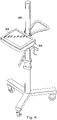
- the bedside controller 300 may also releasably attach to an IV pole 600 via the self-contained mounting structure 303. When so attached, the bedside controller 300 may be rolled next to a patient in the sterile field and thus within reach of a clinician who may operate the controller with a single hand.
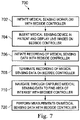
- FIG. 7 is a high-level flowchart illustrating a method 700 of conducting a medical sensing workflow with the bedside controller 300 of Figures 3-4 according to various aspects of the present disclosure.
- the method 700 will be described in the context of an IVUS procedure but may equally apply to any number of medical sensing or treatment procedures, such as an OCT procedure, a FLIVUS procedure, an ICE procedure, etc.
- the method 700 begins at block 702 where a medical sensing workflow is initiated with the bedside controller 300.
- a clinician in the sterile field and adjacent a patient may select the "IVUS" option out of a plurality of modes (e.g., OCT, Chromaflow, FLIVUS, etc) on the bedside controller's GUI to begin the IVUS workflow.
- a plurality of modes e.g., OCT, Chromaflow, FLIVUS, etc
- the clinician may select a 'Live Images' option on the bedside controller's GUI to receive live images from the catheter.
- the clinician may guide the catheter within the patient to a desired position.
- a processing system may collect raw IVUS data from the catheter and process the data to render IVUS images.
- the bedside controller retrieves the IVUS images from the processing system and displays them to a user in real-time. Then, in block 706, after the IVUS catheter has been appropriately positioned in the patient using the live images, the clinician selects a 'Record' option on the bedside controller GUI and begins the catheter pull back. The processing system responds to the record command and begins rendering and storing IVUS images. The method 700 proceeds to block 708 where, after the IVUS catheter pull back has been completed, the clinician terminates the recording of IVUS images via the bedside controller's GUI. Then, in block 710, the clinician at the bedside recalls the captured IVUS images on the bedside controller and finds the IVUS images associated with the area of interest.
- the bedside controller may present a condensed view of all captured images and the clinician may navigate through them using gestures on the bedside controller's touch panel to find the target area.
- the clinician performs measurements on the IVUS images directly on the bedside controller.
- the user of the bedside controller creates measurements by interacting with an image through a series of presses, moves and releases using a finger or stylus on the controller's touch-sensitive display. These actions are interpreted by the bedside controller's internal processor and converted to measurements on the display.
- the clinician may annotate the images using a stylus or another tool compatible with the bedside controller's touch panel.
- the clinician may save the images to the processing system by selecting the appropriate options in the bedside controller GUI. A method of performing measurements on the bedside controller will be described below.
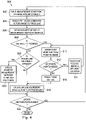
- Figure 8 is high-level flowchart of a method 800 that describes a measurement workflow on the bedside controller 300 of Figures 3A-4 .
- the method 800 may be carried out during block 720 of the method 700 in Figure 7 as part of a medical sensing workflow on intravascular images.
- the method 800 of making measurements on the bedside controller 300 is implemented in measurement software stored in the storage module 324 in the bedside controller.
- a clinician when measuring images, such as intravascular images, a clinician has the option of making different types of measurements such as diameter measurements and area measurements.
- a clinician may either denote the edges of an object by drawings a series of discrete points that are connected in subsequent processing or by drawing a continuous line around the object to the measured.
- the method 800 of performing measurements on images is "smart" in that it does not require a user to select a particular measurement mode prior to interacting with an image on the bedside controller. For instance, when a user performs a series of measurement inputs on the bedside controller, the GUI software interprets the nature (e.g. shape) of a user's measurement inputs, automatically enters either diameter mode, area-point mode or area-draw mode, and outputs the desired measurement on the controller's display.
- the nature e.g. shape
- the method 800 begins at block 802 where an image to be measured is displayed on the bedside controller and a user inputs a measurement start point on the image with an input device.
- the user may use a finger or stylus to indicate a point on a vessel border from which a measurement will commence. Note that prior to selecting the measurement start point, the measurement software did not require the user to select a measurement mode.
- the user without removing the input device from the image after indicating the start point, drags the input device across the image a distance to trace a line. Then, in block 806, the user withdraws the input device from the image at a measurement end point.
- the method 800 proceeds to decision block 808 where the measurement software determines whether the distance between the start point and the end point is less than a threshold value.
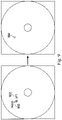
- the threshold value is equivalent to 10 pixels, but, in alternative embodiments, the threshold value may be smaller or larger or measured in different units. Further, in some embodiments, the threshold value is adjustable either manually by a user or automatically based on detected error rates. If the distance is less than the threshold value, the method proceeds to block 810 where the measurement software enters area-point mode and draws a point on the image corresponding to the end point (i.e. where the user lifted the input device from the touch-enabled display). This sequence is illustrated in Figure 9 . Specifically, when a user presses (900) an input device on an image and immediately lifts (902) the input device, the input will be interpreted as a point entry and a point 904 will be drawn on the image.
- the method 800 then proceeds to decision block 812 where it is decided whether additional points are needed to make a measurement on the image. If additional points are needed, the method proceeds to block 814 where a user touches and releases the displayed image at a different location. Note that in this branch of method 800, the measurement software is in area-point mode so that all entries will be interpreted as points and, when an input is detected, a point will be drawn on the image in block 810 regardless of the distance between a start point and end point of the input. If no additional points are needed to make a measurement in decision block 812, the method 800 proceeds to block 816, where a user selects a 'Done' button in the bedside controller GUI to exit area-point mode.
- the measurement software creates an area measurement using the entered points. For example, in an embodiment directed toward vessel measurement, the measurement software connects the entered points to create a bounding circle at the vessel's outer edge. In one embodiment, the measurement software uses the entered points as seed points to assist edge detection algorithms.
- the method 800 proceeds to decision block 820 where the measurement software determines whether the drawn line is "relatively straight". That is, it determines whether the user desires to measure a diameter with a line or an area with a enclosed shape. As shown in Figure 10 , to make such a determination, the measurement software compares intervening points on the traced line between a start point 1000 and an end point 1002 against a boundary threshold 1004. If all intervening points are within the boundary threshold 1004, the measurement software determines that the user desires to make a diameter measurement and transforms the traced line into a straight line 1006 extending from the start point to the end point.
- the diameter measurement is thus based on the length of the straight line 1006.
- the measurement software may employ different methods for determining whether the user desires to make a diameter measurement or an area measurement, such as detecting whether intervening points between start and end points increase in distance from the start point before decreasing in distance from the start point or detecting whether the traced line extending through the start point, at least one intervening point, and the end point is arcuate past a threshold degree.
- the method proceeds to block 822 where the measurement software enters diameter mode and outputs a measurement of the straight line 1006 created between the start and end points.
- the method 800 proceeds to 818 where the measurement software enters area-draw mode. As shown in Figure 11 , the traced line 1100 between start point 1102 and end point 1104 extends outside of a boundary threshold (not shown) and is thus not relatively straight, prompting the measurement software to enter area-draw mode. Once this determination is made, the software connects the start and ends points to create a unbroken bounding line 1006 from which an area may be calculated. After an area measurement has been made in block 818 (either in area-point mode or area-draw mode), the method proceeds to decision block 824 where it is determined if another measurement needs to be done. If so, the method proceeds back to block 802 where a user selects another start point on the image without first selecting a measurement mode. If all measurements have been completed, the method 800 ends.
- workflows for some medical sensing procedure may allow for additional measurement modes, such as volumetric measurements.
- additional measurement modes such as volumetric measurements.
- a user may initiate any such additional measurement modes without first selecting a measurement mode, thus simplifying the workflow.
- the steps in methods 700 and 800 described above may be completed over the course of more than one patient visit to a catheter lab.
- the touch-enabled integrated bedside controllers 102 and 300 may be used to control and measure non-cardiovascular diagnostic data such as data from cranial or peripheral arteries, as well as data from non-vascular body portions. Further, the controllers 102 and 300 may be used to control an MRI workflow and measure MRI image data, or may be utilized in computer assisted surgery (CAS) applications. Further, the modules described above in association with the bedside controller 300 may be implemented in hardware, software, or a combination of both.
- the bedside controller may be designed to enable user control in many different network settings such as ad-hoc networks, local area networks, client-server networks, wide area networks, internets, and the controller may have a number of form factors such as a tablet, a smartphone, a laptop, or any other similar device. It is understood that such variations may be made in the foregoing without departing from the scope of the present disclosure. Accordingly, it is appropriate that the appended claims be construed broadly and in a manner consistent with the scope of the present disclosure.
Landscapes
- Health & Medical Sciences (AREA)
- Life Sciences & Earth Sciences (AREA)
- Engineering & Computer Science (AREA)
- Biomedical Technology (AREA)
- Physics & Mathematics (AREA)
- Public Health (AREA)
- General Health & Medical Sciences (AREA)
- Medical Informatics (AREA)
- Heart & Thoracic Surgery (AREA)
- Animal Behavior & Ethology (AREA)
- Veterinary Medicine (AREA)
- Biophysics (AREA)
- Pathology (AREA)
- Molecular Biology (AREA)
- Surgery (AREA)
- General Engineering & Computer Science (AREA)
- Theoretical Computer Science (AREA)
- Radiology & Medical Imaging (AREA)
- Nuclear Medicine, Radiotherapy & Molecular Imaging (AREA)
- Human Computer Interaction (AREA)
- General Physics & Mathematics (AREA)
- Vascular Medicine (AREA)
- Anesthesiology (AREA)
- Hematology (AREA)
- High Energy & Nuclear Physics (AREA)
- Oral & Maxillofacial Surgery (AREA)
- Dentistry (AREA)
- Optics & Photonics (AREA)
- Business, Economics & Management (AREA)
- General Business, Economics & Management (AREA)
- Epidemiology (AREA)
- Primary Health Care (AREA)
- Measuring And Recording Apparatus For Diagnosis (AREA)
- Ultra Sonic Daignosis Equipment (AREA)
- Acoustics & Sound (AREA)
Description
- Embodiments of the present disclosure relate generally to the field of medical devices and, more particularly, to a medical measuring system and associated methods of use.
- Innovations in diagnosing and verifying the level of success of treatment of disease have progressed from solely external imaging processes to include internal diagnostic processes. In addition to traditional external image techniques such as X-ray, MRI, CT scans, fluoroscopy, and angiography, small sensors may now be placed directly in the body. For example, diagnostic equipment and processes have been developed for diagnosing vasculature blockages and other vasculature disease by means of ultra-miniature sensors placed upon the distal end of a flexible elongate member such as a catheter, or a guide wire used for catheterization procedures. For example, known medical sensing techniques include intravascular ultrasound (IVUS), forward looking IVUS (FL-IVUS), fractional flow reserve (FFR) determination, a coronary flow reserve (CFR) determination, optical coherence tomography (OCT), trans-esophageal echocardiography, and image-guided therapy. Traditionally, many of these procedures are carried out by a multitude of physicians and clinicians, where each performs an assigned task. For example, a physician may stand next to a patient in the sterile field and guide the insertion and pull back of an imaging catheter. A clinician near the physician may control the procedure workflow with a controller, for example by starting and stopping the capture of images. Further, after images have been captured, a second clinician in an adjacent control room working at a desktop computer may select the images of interest and make measurements on them. Typically, the physician in the catheter lab must instruct the clinician in the control room on how to make such measurements. This may lengthen the time of the procedure, increase the cost of the procedure, and may lead to measurement errors due to miscommunication or clinician inexperience. Further, when making measurements on medical sensing images, a clinician may typically have to select a measurement mode prior to making any measurements, reducing the efficiency of the medical sensing workflow.
- Accordingly, while the existing devices and methods for conducting medical sensing workflows have been generally adequate for their intended purposes, they have not been entirely satisfactory in all respects.
-
US 2005/049509 is directed to a minimally invasive system and method for monitoring changes in a cervix opening during labor, including changes in its diameter. The system having a probe and a monitoring unit serve to monitor periodically the cervix opening during labor and obtain measurements of the diameter of the cervix opening. The probe primarily includes a camera for imaging the cervix opening, a lens to provide an optimal field of view for the camera at close range to the cervix opening, a light source to illuminate the cervix and a balloon to expand the vagina around the probe and position the probe to allow unobstructed imaging of the cervix. The monitoring unit which controls the probe to acquire images of the cervix and receives and processes image data from the probe includes a processor which uses image segmentation techniques to identify and measure the opening of the cervix and generates data signals. The monitoring unit also includes an image display which displays information based on the data signals for viewing by health care providers and/or the patient, including graphic images of the cervix opening and other text information relating to the cervix opening as an indicator of the progress of labor. In one embodiment, the processor implements segmentation techniques and/or blob analysis algorithms to analyze the images of the cervix to identify the opening and measure its diameter. Other algorithms may also be implemented to correct for any spatial distortion, particularly barrel distortion. -
EP 1 381 315 describes a method for analyzing tubular structures in a patient, including steps of: selecting a region of interest and a location within the region of interest from a displayed tube-shaped tree representative of a tubular structure in a patient; identifying a centerline of a structure within the tube-shaped tree within the region of interest; and displaying one or more views of the region of interest. The view or views are selected from at least a segmented 3-D view having the region of interest identified, a curved view of the selected branch , a reformatted view dependent upon the identified centerline, and a 3-D view dependent upon the identified centerline. -
EP 1 229 822 describes a parameter evaluation system comprising a boundary input device for setting boundaries in a variation range of one or more parameters, thereby to define regions within said variation range, a label input device for associating labels with said regions, a rule input device for setting rules to associate at least one of a plurality of output recommendations with each of said regions and with combinations thereof and an output device to present a user with an output recommendation associated with a region or combination thereof corresponding to at least one measured parameter input to said system. The input device is a parameter value region selection and categorization input device for setting boundaries in the variation range of the parameter, defining regions therebetween and categorizing the regions.; The device comprises a visual representation of the variation range as a linear continuum, a continuum divider for visually dividing the continuum at user selectable points therealong, the points corresponding to values of the parameter, thereby to define regions therebetween and a category definer for defining categories for association with the regions. The device has an application in a patient monitoring kit under remote supervision of a physician. A parameter evaluation system for a patient in a network with doctor. - In Xinyu Wang et al: "On-line sketch recognition for course of action diagrams", Mechatronics and Automation (ICMA), 4 August 2010, pages 465-459, a robust method of sketch recognition for course of action (COA) diagrams is presented. User input is through free-hand sketching. COA symbols are recognized incrementally and the informal sketching input is replaced with formal vector graphs or images of the symbols. Multi-stroke COA symbols are divided into temporally continuous uni-stroke shapes. Firstly, it removes over-crossed end part of the uni-stroke shapes. Then, it extracts invariant geometric features of convex hull, largest-area inscribed and smallest-area enclosing polygons, perimeter and area ratios, and distinctive features of the concave and the open ended. Thirdly, the uni-stroke shapes are recognized by support vector machines (SVM). Fourthly, an intermediate feature recognizer is used to recognize shapes of intermediate complexity such as a dashed line, which improves sketch recognition performance in the COA domain. Finally, the system uses the LADDER shape definition language to represent the geometric properties of shapes, and is capable of recognizing common COA symbols of multi-stroke sketches and gesture commands with a recognition accuracy of more than 98%.
-
US 2006/227140 describes methods to provide methods for beautifying sketches. Methods are disclosed for determining segments of drawings that represent geometric primitives and implied geometric constraints. Beautification methods provide for replacement of sketched primitives and over- and under-sketched drawings. After beautification methods provide for checking the initial segmentation of the sketch to determine whether false segmentation points were identified. Methods are also disclosed to provide for searching of drawings based upon a beautified sketch. User interactivity is provided to further refine search results. - In Jenkins D L etal: "Applying constraints to enforce users' intentions in free-hand 2-d sketches", Intelligent Systems Engineering, Institution of Electrical Engineers, vol. 1, no. 1, 21 September 1992, pages 31-49, Easel, a smart CAD package which attempts to analyse and tidy up sketches as a designer draws them, is described. This paper presents an overview of the system, details of its user interface and the curve-fitting approach. The main part of the paper is concerned with automatic methods to infer and enforce geometric relations intended by the user. The authors also discuss their conclusions as regards performance.
-
US 2004/040091 describes a holding device for medical instruments at a patient's bed, which are accommodated in suspension components. Holding devices for various medical instruments, such as respirators and accessories, infusion and secretion bags, measuring instruments and disposable articles, are used at patients' beds in many areas. A frequent drawback of prior-art holding devices is that the support at the patient's bed is unstable because the holding devices are suspended only loosely in a rail or handle. The holding device according to the present invention guarantees stable fastening at the patient's bed. It comprises a horizontal crossbeam, which is fixed on the sides of a peripheral strap at the foot end of the patient's bed via, e.g., fixing means designed as metal claws. Two vertical suspension carriers with openings for receiving suspension components have suspension sections at their upper ends for suspension on the straps. It would also be possible to suspend the suspension sections on a wall rail or cabinet rail. - In one example not necessarily covered by the claims, the present application describes a method of performing measurements on medical images with a bedside controller. The method includes receiving, through a touch-sensitive display on the bedside controller, a user measurement input on an image displayed on the display, the user measurement input including a start point defined by a point of initial contact with the touch-sensitive display and an end point defined by a point of last contact with the touch-sensitive display. The method also includes selecting a measurement mode based on a shape of the user measurement input and calculating a measurement value associated with the user measurement input based on the measurement mode.
- In some instances, the method of performing measurements may include selecting one of a diameter measurement mode and an area measurement mode based on the shape of the user measurement input.
- In another example not necessarily covered by the claims, the present application describes a bedside controller. The bedside controller includes a housing, the housing including self-contained mounting structure, a touch-sensitive display disposed within a surface of the housing and configured to display images and receive user input on the surface, a processor disposed within the housing, and a communication module disposed within the housing, communicatively coupled to the processor, and configured to transmit and receive medical data from a processing system. The bedside controller also includes a non-transitory computer readable storage module disposed within the housing, communicatively coupled to the processor, and including a plurality of instructions stored therein and executable by the processor. The plurality of instructions include instructions for receiving, through the touch-sensitive display, a user measurement input on an image displayed on the display, instructions for selecting a measurement mode based on a shape of the user measurement input, and instructions for calculating a measurement value associated with the user measurement input based on the measurement mode.
- In another exemplary aspect, the present disclosure is directed to a medical measuring system. The medical procedure workflow system includes a medical sensor device configured to gather medical data from a patient and a processing system communicatively coupled to the medical sensor device and operable to receive the medical data from the medical sensor device, the processing system being further operable to transform the medical data into medical images representative of the patient. The system also includes a bedside controller communicatively coupled to the processing system and operable to receive the medical images from the processing system and display the medical images on a touch-sensitive display, the bedside controller being further configured to receive, through the touch-sensitive display, a user measurement input on a medical image displayed on the display, select a measurement mode based on a shape of the user measurement input, and calculate a measurement value associated with the user measurement input based on the measurement mode.
- In some instances, the bedside controller may be configured to receive the user measurement input while in a sterile field surrounding the patient. Additionally, the bedside controller may be configured to select one of a diameter measurement mode and an area measurement mode based on the shape of the user measurement input.
- In yet another example not necessarily covered by the claims, the present application describes a method of conducting a medical workflow with a touch-sensitive bedside controller. The method includes initiating a medical workflow using a graphical user interface on the bedside controller, positioning an imaging tool within a patient's body based on images captured by the imaging tools and displayed on the bedside controller, controlling the commencement and termination of a recordation of images captured by the imaging tool using the graphical user interface on the bedside controller, navigating through the recorded images to identify an image of interest using the graphical user interface on the bedside controller, and performing measurements on the image of interest using the graphical user interface on the bedside controller.
- In some instances, the performing measurements may include touching and releasing portions of the image of interest as it is displayed on the bedside controller to make one of an area measurement and a diameter measurement.
- In a further example not necessarily covered by the claims, the present application describes a bedside controller. The bedside controller include a housing, a touch-sensitive display disposed within a surface of the housing and configured to display images and receive user input on the surface, and a processor disposed within the housing. The bedside controller also includes a communication module disposed within the housing, communicatively coupled to the processor, and configured to transmit and receive medical data and a non-transitory computer readable storage module disposed within the housing, communicatively coupled to the processor, and including a plurality of instructions stored therein and executable by the processor. The plurality of instructions include instructions for rendering a graphical user interface (GUI) on the touch-sensitive display, instructions for displaying images of a patient as they are being captured by an imaging tool disposed within the patient's body, and instructions for initiating and terminating a recordation of the images based on user input to the GUI. The plurality of instructions also include instructions for displaying the recorded images within the GUI so that a user may identify an image of interest and instructions for making a measurement on the image of interest based on a user measurement input to the GUI.
- In another example not necessarily covered by the claims, the present application describes a bedside controller. The bedside controller includes an integrally formed housing and self-contained mounting structure disposed on the housing. The mounting structure includes a mounting channel defined in the housing and a retaining clamp disposed above the mounting channel and configured to releasably secure a mounting platform within the mounting channel such that the bedside controller is mounted to the mounting platform. The bedside controller also includes a touch-sensitive display disposed within a surface of the housing and configured to display images and receive user input on the surface, a processor disposed within the housing, a communication module disposed within the housing, communicatively coupled to the processor, and configured to transmit and receive medical data, and a battery disposed within the integrally formed housing and electrically coupled to the touch-sensitive display, the processor, and the communication module.
- In some instances, the self-contained mounting structure may be configured to releasably secure the bedside controller to the bed rail in such a manner that the display of the bedside controller is generally parallel with a top surface of a table associated with the bed rail.
- In yet another example not necessarily covered by the claims, the present application describes a method of releasably mounting a bedside controller to a mounting platform associated with a patient undergoing an intravascular workflow. The method includes pivoting a retaining clamp to an open position, the retaining clamp being disposed on the bedside controller such that it extends over a mounting channel defined in a housing of the bedside controller, positioning the bedside controller such that the mounting platform extends through the mounting channel, and releasing the retaining clamp such that it engages the mounting platform to releasably secure the mounting platform within the mounting channel, thereby mounting the bedside controller to the mounting platform. The method also includes viewing intravascular medical information associated with the patient displayed on a touch-sensitive display of the bedside controller and inputting user inputs on the touch-sensitive display to manipulate the medical information displayed on the touch-sensitive display.
-
-
Figure 1 is a schematic drawing depicting a medical sensing system including a bedside controller according to one embodiment of the present disclosure. -
Figure 2 is a schematic drawing depicting a medical sensing system including a wireless bedside controller according to another embodiment of the present disclosure. -
Figure 3A is a diagrammatic perspective view of a bedside controller. -
Figure 3B is a diagrammatic rear perspective view of the bedside controller ofFigure 3A . -
Figure 3C is a diagrammatic perspective view of the bedside controller ofFigure 3A mounted to a bed rail. -
Figure 4 is a functional block diagram of the bedside controller ofFigures 3A and3B according to aspects of the present disclosure. -
Figure 5 is a diagrammatic perspective view of a multi-modality mobile processing system with the bedside controller ofFigures 3A and3B attached thereto. -
Figure 6 is a diagrammatic perspective view of the bedside controller ofFigures 3A and3B releasably mounted on an IV pole. -
Figure 7 is a high-level flowchart illustrating a method of conducting a medical sensing workflow with a bedside controller according to various aspects of the present disclosure. -
Figure 8 is high-level flowchart of a method that describes a measurement workflow conducted on a bedside controller according to various aspects of the present disclosure. -
Figures 9-11 are partial screen images illustrating various aspects of the method ofFigure 8 . - For the purposes of promoting an understanding of the principles of the present disclosure, reference will now be made to the embodiments illustrated in the drawings, and specific language will be used to describe the same. It will nevertheless be understood that no limitation of the scope of the disclosure is intended. Any alterations and further modifications in the described devices, instruments, methods, and any further application of the principles of the disclosure as described herein are contemplated as would normally occur to one skilled in the art to which the disclosure relates. In particular, it is fully contemplated that the features, components, and/or steps described with respect to one embodiment may be combined with the features, components, and/or steps described with respect to other embodiments of the present disclosure.
-
Figure 1 is a schematic drawing depicting amedical sensing system 100 including abedside controller 102 according to one embodiment of the present disclosure. In general, themedical sensing system 100 provides for coherent integration and consolidation of multiple forms of acquisition and processing elements designed to be sensitive to a variety of methods used to acquire and interpret human biological physiology and morphological information. More specifically, insystem 100, thebedside controller 102 is a touch-enabled, integrated computing device for the acquisition, control, interpretation, measurement, and display of multi-modality medical sensing data. In the illustrated embodiment, thebedside controller 102 is a tablet-style touch-sensitive computer that provides user controls and diagnostic images on a single surface. In themedical sensing system 100, thebedside controller 102 is operable to present workflow control options and patient image data via graphical user interfaces (GUIs) corresponding to a plurality of medical sensing modalities. Thebedside controller 102 will be described in greater detail in association withFigures 3A ,3B , and4 . - In the illustrated embodiment, the
medical sensing system 100 is deployed in acatheter lab 104. Thecatheter lab 104 may be used to perform on apatient 106 any number of medical sensing procedures alone or in combination such as, by way of example and not limitation, angiography, intravascular ultrasound (IVUS), virtual histology (VH), forward looking IVUS (FL-IVUS), intravascular photoacoustic (IVPA) imaging, fractional flow reserve (FFR) determination, coronary flow reserve (CFR) determination, optical coherence tomography (OCT), computed tomography, intracardiac echocardiography (ICE), forward-looking ICE (FLICE), intravascular palpography, transesophageal ultrasound, or any other medical sensing modalities known in the art. In addition to controlling medical sensing systems, the bedside controller may be used to cooperate with and control medical treatment systems such as, for example but without limitation, those used for stent placement, coil embolism, ablation therapy, kidney stone treatments, basket placement in a cystoscopy, tumor removal, and chemical therapies. Thecatheter lab 104 further includes asterile field 105 that encompasses the portions of the catheter lab surrounding thepatient 106 on a procedure table 109 and aclinician 107, who may perform any number of medical sensing procedures or treatments. As shown inFigure 1 , thebedside controller 102 may be positioned within thesterile field 105 and may be utilized by theclinician 107 to control a workflow of a medical sensing procedure or treatment being performed on thepatient 106. For example, theclinician 107 may initiate the procedure workflow, watch real-time IVUS images captured during the procedure, and make measurements on the IVUS images all using thebedside controller 102 inside of thesterile field 105. In alternative embodiments, thebedside controller 102 may be utilized outside of thesterile field 105, for instance, in other locations within thecatheter lab 104 or in a control room adjacent to the catheter lab. A method of utilizing thebedside controller 102 to control a medical sensing workflow or treatment workflow will be discussed in greater detail in association withFigures 7 and8 . - In the embodiment illustrated in
Figure 1 , themedical sensing system 100 additionally includes a number of interconnected medical sensing-related tools in thecatheter lab 104 to facilitate a multi-modality workflow procedure, such as anIVUS catheter 108, an IVUS patient isolation module (PIM) 112, anOCT catheter 110, andOCT PIM 114, an electrocardiogram (ECG)device 116, anangiogram system 117, aboom display 122, and amulti-modality processing system 124. Thebedside controller 102,PIMs ECG device 116,angiography system 117, andboom display 122 are communicatively coupled to theprocessing system 124. In one embodiment, theprocessing system 124 is a computer workstation with the hardware and software to acquire, process, and display multi-modality medical sensing data, but in other embodiments, the processing system may be any other type of computing system operable to process medical sensing data. For example, during an IVUS workflow, theprocessing system 124 is operable to accept raw IVUS data from theIVUS PIM 112, transform it into IVUS images, and make the images available to thebedside controller 124, so that they may be displayed to theclinician 107 for analysis. In the embodiments in which theprocessing system 124 is a computer workstation, the system includes at least a processor such as a microcontroller or a dedicated central processing unit (CPU), a non-transitory computer-readable storage medium such as a hard drive, random access memory (RAM), and/or compact disk read only memory (CD-ROM), a video controller such as a graphics processing unit (GPU), and a network communication device such as an Ethernet controller. Further, themulti-modality processing system 124 is communicatively coupled to adata network 125. In the illustrated embodiment, thedata network 125 is a TCP/IP-based local area network (LAN), however in other embodiments, it may utilize a different protocol such as Synchronous Optical Networking (SONET), or may be a wide area network (WAN). Theprocessing system 124 may connect to various resources via thenetwork 125, such as a Digital Imaging and Communications in Medicine (DICOM) system, a Picture Archiving and Communication System (PACS), and a Hospital Information System.U.S. Patent Application No. 61/473,570, entitled "MULTI-MODALITY MEDICAL SENSING SYSTEM AND METHOD" and filed on April 8, 2011 - In the
medical sensing system 100, theIVUS PIM 112 andOCT PIM 114 are operable to respectively receive medical sensing data collected from thepatient 106 by theIVUS catheter 108 andOCT catheter 110 and are operable to transmit the received data to theprocessing system 124. In one embodiment, theIVUS PIM 112 andOCT PIM 114 transmit the medical sensing data over a Peripheral Component Interconnect Express (PCIe) data bus connection, but, in other embodiments, they may transmit data over a USB connection, a Thunderbolt connection, a FireWire connection, or some other high-speed data bus connection. Additionally, theECG device 116 is operable to transmit electrocardiogram signals or other hemodynamic data frompatient 106 to theprocessing system 124. To aid the clinician in data capture, thebedside controller 102 is operable to display the ECG data along side medical sensing data. Further, in some embodiments, theprocessing system 124 may be operable to synchronize data collection with thecatheters ECG 116. Further, theangiogram system 117 is operable to collect x-ray, computed tomography (CT), or magnetic resonance images (MRI) of thepatient 106 and transmit them to theprocessing system 124. After the x-ray, CT, or MRI data has been processed into human-readable images by theprocessing system 124, theclinician 107 may navigate the GUI on thebedside controller 124 to retrieve the images from theprocessing system 124 and display them on the controller. In some embodiments, theprocessing system 124 may coregister image data from angiogram system 117 (e.g. x-ray data, MRI data, CT data, etc.) with sensing data from the IVUS andOCT catheters bedside controller 124. In one embodiment, a clinician may rotate, zoom, and otherwise manipulate such 3-D images on thebedside controller 102 using simultaneous touch inputs (i.e. multitouch) and gestures. - Additionally, in the illustrated embodiment of
Figure 1 , medical sensing tools insystem 100, are communicatively coupled to theprocessing system 124 via a wired connection such as a standard copper link or a fiber optic link. Specifically, thebedside controller 124 may be communicatively and/or electrically coupled to theprocessing system 124 via a Universal Serial Bus (USB) connection, a Power-over-Ethernet connection, a Thunderbolt connection, a FireWire connection, or some other high-speed data bus connection. - However, in an alternative embodiment, such as that shown in
Figure 2 , the medical sensing tools may communicate wirelessly. In that regard,Figure 2 is a schematic drawing depicting amedical sensing system 200 including awireless bedside controller 202 according to another embodiment of the present disclosure. Themedical sensing system 200 is similar to thesystem 100 ofFigure 1 but the medical sensing tools including thewireless bedside controller 202, awireless IVUS PIM 204, and awireless OCT PIM 206 communicate with awireless network 208 via wireless networking protocols. For example, thebedside controller 202 may send and receive workflow control parameters, medical sensing images, and measurement data to and from a remote processing system via IEEE 802.11 Wi-Fi standards, Ultra Wide-Band (UWB) standards, wireless FireWire, wireless USB, Bluetooth, or another high-speed wireless networking standard. Such wireless capability allows theclinician 107 to more freely position thebedside controller 202 inside or outside of thesterile field 105 for better workflow management. - With reference now to
Figures 3A ,3B ,3C and4 ,Figure 3A is a diagrammatic perspective view of abedside controller 300,Figure 3B is a diagrammatic rear perspective view of the bedside controller,Figure 3C is a diagrammatic perspective view of the bedside controller mounted to a bed rail, andFigure 4 is a functional block diagram of thebedside controller 300 according to aspects of the present disclosure. Thebedside controller 300 is similar to thebedside controllers medical sensing systems bedside controller 300 generally improves system control available to a clinician working at a patient table. For instance, giving a clinician both workflow control and measurement capability within the sterile field reduces errors and improves workflow efficiency. - As show in
Figure 3A , thebedside controller 300 includes an integrally formedhousing 302 that is easy to grasp and move around a catheter lab or other medical setting. In one embodiment, the integrally formedhousing 302 may be seamlessly molded from materials such as thermoplastic or thermosetting plastic or moldable metal. In other embodiments, the integrally formedhousing 302 may comprise a plurality of housing portions fixedly bonded in a substantially permanent manner to form an integral housing. Thehousing 302 is resistant to fluids, and, in one embodiment, may have a rating of IPX4 against fluid ingress as defined by the International Electrotechnical Commission (IEC) standard 60529. In other embodiments in which thehousing 302 may be used in different environments, the hub may have a different fluid ingress rating. In the illustrated embodiment, thehousing 302 is about 10.5 inches in width, about 8.25 inches in height, and has as thickness of about 2.75 inches. In alternative embodiments, the housing may have a different width, height, or thickness that is similarly conducive to portability. - As shown in
Figure 3B , thehousing 302 further includes self-containedmounting structure 303 disposed on the housing. In the illustrated embodiment, the mounting structure is disposed near an outer edge of the housing. The mountingstructure 303 allows thebedside controller 300 to be releasably mounted in a variety of places in and out of a catheter lab in a self-contained manner. That is, thebedside controller 300 may be directly secured to another object without the use of a separate external mount. In the illustrated embodiment, the mountingstructure 303 includes a mountingchannel 304 and a retainingclamp 305 that pivots over the mounting channel to secure a mounting platform therewithin. The mountingchannel 304 is defined by a longerfront wall 350, atop wall 352, and ashorter back wall 354, and the retaining clamp includes aslot 356 that extends through the clamp in a manner generally parallel to the mounting channel. Thefront wall 350 and theback wall 354 are generally perpendicular to a touch-sensitive display 307 in thehousing 302, and thetop wall 352 is generally parallel to thedisplay 307. In the illustrated embodiment, the retaining clamp is spring-loaded and releasably exerts pressure on objects situated in the mounting channel. In alternative embodiments, the retaining clamp may be configured differently and exert force via mechanisms other than springs. - As shown in
Figure 3C , in operation, thebedside controller 300 may be releasably secured to a mounting platform, for example abed rail 306, by pivoting the mountingclamp 305 to an open position, positioning the controller such that the rail extends through the length of thechannel 304, and releasing the clamp such that it secures the rail within the channel. When therail 306 is positioned in the mountingchannel 304 and theclamp 305 is holding it therein, three surfaces of the rail are respectively engaged by thefront wall 350, thetop wall 352, and theback wall 354, and a fourth surface of the rail extends through theslot 356 in theclamp 305. In this manner, the mountingstructure 303 may maintain thebedside controller 300 in a position generally parallel to a procedure table 350 associated with thebed rail 306, as shown inFigure 3B . Described differently, the mountingstructure 303 is a cantilevered mounting structure in that it secures one end of the controller to an object while the majority of the controller extends away from the object in an unsupported manner. Such a cantilevered position allows for a display of the controller to be both readable and at a comfortable input angle for an operator. Further, the self-containedmounting structure 303 allows thebedside controller 300 to be quickly released from thebed rail 306 and reattached to an IV pole, a cart on which a processing system is deployed, or other location in or out of the sterile field to allow for convenient workflow control and image analysis. In alternative embodiments the mountingstructure 303 of the bedside controller may vary from the design illustrated inFigures 3A and3B and include additional and/or different components to allow for self-contained mounting. - Embedded into the front of the
housing 302 is the touch-sensitive display 307 that comprises both atouch panel 308 and aflat panel display 309. Thetouch panel 308 overlays theflat panel display 308 and accepts user input via human touch, stylus touch, or some other analogous input method. In other words, the touch-sensitive display 307 displays images and accepts user input on the same surface. In the current embodiment, thetouch panel 308 is a resistive-type panel, but in alternative embodiments it may be a capacitive-type panel, projective-type panel, or some other suitable type of touch enabled input panel. Further, thetouch panel 308 is operable to accept multiple inputs simultaneously (multitouch), for instance, to enable rotation of a three-dimensional rendering of a vessel along multiple axes. Additionally, thetouch panel 308 is capable of receiving input when asterile drape 301 is covering thebedside controller 300 and also when a user is gloved. Thetouch panel 308 is controlled by atouch controller 310 disposed within thehousing 302. Further, when a clinician makes contact with thetouch panel 308, the touch panel is operable to provide haptic feedback via ahaptics controller 312 andhaptics drivers 314. This haptic technology is operable to simulate a plurality of sensations on thetouch panel 308 by varying the intensity and frequency of vibrations generated when a user contacts the touch panel. In some embodiments, thehousing 302 may include a sheath configured to store a stylus therein. Thus, a clinician may remove the stylus from the sheath in the housing to make measurements on the bedside controller and store it when the measurements have been completed. - Beneath the
touch panel 308 is theflat panel display 309 that presents a graphical user interface (GUI) 316 to a user. In the illustrated embodiment, theflat panel display 309 is a LCD display but in alternative embodiments, it may be a different type of display such an LED display or an AMOLED display. In the illustrated embodiment, theflat panel display 309 is illuminated by a LEDbacklight power inverter 318. As mentioned above, theGUI 316 not only allows a clinician to control a medical sensing workflow but also make measurements on images captured from a patient in the sterile field. A method of interacting with theGUI 316 to make vessel measurements will be discussed in greater detail in association withFigures 8-11 . - The
bedside controller 300 includes a singleboard processing platform 320 within thehousing 302 that is operable to render theGUI 316 and process user input. In the illustrated embodiment, the processing platform has a pico form factor and includes integrated processing components such as aprocessor 321,system memory 322, graphics processing unit (GPU),communications module 323, and I/O bus controller. In some embodiments, theprocessor 321 may be a low power processor such as an Intel Atom® processor or a ARM-based processor, and thecommunications module 323 may be a 10/100/1Gb Ethernet module. And, the I/O bus controller may be a Universal Serial Bus (USB) controller. Thebedside controller 300 further includes astorage module 324 that is a non-transitory computer readable storage medium operable to store an operating system (i.e. software to render and control the GUI), image manipulation software, medical sensing data and images received from a processing system, and other medical sensing-related software. Theprocessor 321 is configured to execute software and instructions stored on thestorage module 324. In the illustrated embodiment, thestorage module 324 is a solid state drive (SSD) hard drive communicatively coupled to theprocessing platform 320 via a SATA connection, but, in alternative embodiments, it may be any other type of non-volatile or temporary storage module. Thebedside controller 300 further includes awireless communications module 326 communicatively coupled to theprocessing platform 320. In some embodiments, the wireless communications module is a IEEE 802.11 Wi-Fi module, but in other may be a Ultra Wide-Band (UWB) wireless module, a wireless FireWire module, a wireless USB module, a Bluetooth module, or another high-speed wireless networking module. - In the illustrated embodiment, the
bedside controller 300 is powered via both a wired 12VDC power-over-Ethernet (PoE)connection 328 and abattery 330 disposed within thehousing 302. In one embodiment, thebattery 330 may be sealed within the integrally formedhousing 302 and may be recharged through electrical contacts disposed on the exterior of the housing and electrically coupled to the battery. As shown in the embodiment ofFigure 3B , thefront wall 350 may include one or moreelectrical contacts 358 through which thebattery 330 may be charged when the controller is mounted to objects with compatible charging structure. In other embodiments, thehousing 302 may include a battery compartment with a removable cover to permit battery replacement. Such a battery compartment cover may be resistant to fluid ingress (e.g., with an IPX4 rating). Thebedside controller 300 may be coupled to a processing system in the catheter lab via thePoE connection 328, over which it receives medical sensing images that have been captured from the patient and rendered on the processing system. In operation, when the bedside controller is coupled to thePoE connection 328, it receives power and communications over the same physical wire. When thebedside controller 300 is disconnected from thePoE connection 328, it runs on battery power and receives data wirelessly via thewireless communications module 326. When used wirelessly in a catheter lab, the bedside controller may directly communicate with a processing system (i.e. in an ad-hoc wireless mode), or, alternatively, it may communicate with a wireless network that serves a plurality of wireless devices. In alternative embodiments, thebedside controller 300 may receive power and data through different wired connections, or receive data communications through a wired data connection and power from thebattery 330, or receive data communications through thewireless module 326 and power from a wired electrical connection. In some embodiments, thebedside controller 300 may be used in a semi-wireless configuration, in which thebattery 330 provides backup power to the controller when the controller is temporarily disconnected from a wired power source. For example, if at the beginning of a procedure, thebedside controller 300 is connected to a PoE connection (or other type of wired connection) and during the procedure the controller must be disconnected from the PoE connection to allow for a cabling adjustment, thebattery 330 may keep the controller alive until a PoE connection can be reestablished. In this manner, a full power-off and reboot of thecontroller 300 is avoided during a procedure. As shown inFigure 4 , a DC-DC power converter 332 converts input voltage to a voltage usable by theprocessing platform 320. - It is understood that although the
bedside controller 300 in the illustrated embodiments ofFigures 3 and4 includes specific components described herein, the bedside controller may include any number of additional components, for example a charge regulator interposed between the electrical contacts and the battery, and may be configured in any number of alternative arrangements in alternative embodiments. - With reference now to
Figures 5 and6 , illustrated are examples of locations in which thebedside controller 300 may be mounted.Figure 5 is a diagrammatic perspective view of a multi-modalitymobile processing system 500. Theprocessing system 500 is disposed on acart 502 that enables the processing system to be easily moved between different locations such as different catheter labs. As shown inFigure 5 , thebedside controller 300 is mounted to thecart 502 so that it may be transported to catheter labs with the processing system. Thebedside controller 300 is releasably secured to the cart via the self-containedmounting structure 303 that is built into thehousing 302. Further, in some embodiments, thecart 502 may include a dock for thebedside controller 300 such that when the controller is docked on the cart its battery is recharged through theelectrical contacts 358 disposed on thehousing 302. As shown inFigure 6 , thebedside controller 300 may also releasably attach to anIV pole 600 via the self-containedmounting structure 303. When so attached, thebedside controller 300 may be rolled next to a patient in the sterile field and thus within reach of a clinician who may operate the controller with a single hand. -
Figure 7 is a high-level flowchart illustrating amethod 700 of conducting a medical sensing workflow with thebedside controller 300 ofFigures 3-4 according to various aspects of the present disclosure. Themethod 700 will be described in the context of an IVUS procedure but may equally apply to any number of medical sensing or treatment procedures, such as an OCT procedure, a FLIVUS procedure, an ICE procedure, etc. Themethod 700 begins atblock 702 where a medical sensing workflow is initiated with thebedside controller 300. Using an IVUS procedure as an example, a clinician in the sterile field and adjacent a patient may select the "IVUS" option out of a plurality of modes (e.g., OCT, Chromaflow, FLIVUS, etc) on the bedside controller's GUI to begin the IVUS workflow. Next, inblock 704, after an IVUS imaging catheter has been inserted into the patient, the clinician may select a 'Live Images' option on the bedside controller's GUI to receive live images from the catheter. Using the real-time images, the clinician may guide the catheter within the patient to a desired position. In typical embodiments, a processing system may collect raw IVUS data from the catheter and process the data to render IVUS images. The bedside controller retrieves the IVUS images from the processing system and displays them to a user in real-time. Then, inblock 706, after the IVUS catheter has been appropriately positioned in the patient using the live images, the clinician selects a 'Record' option on the bedside controller GUI and begins the catheter pull back. The processing system responds to the record command and begins rendering and storing IVUS images. Themethod 700 proceeds to block 708 where, after the IVUS catheter pull back has been completed, the clinician terminates the recording of IVUS images via the bedside controller's GUI. Then, inblock 710, the clinician at the bedside recalls the captured IVUS images on the bedside controller and finds the IVUS images associated with the area of interest. Specifically, the bedside controller may present a condensed view of all captured images and the clinician may navigate through them using gestures on the bedside controller's touch panel to find the target area. Finally, inblock 720, the clinician performs measurements on the IVUS images directly on the bedside controller. The user of the bedside controller creates measurements by interacting with an image through a series of presses, moves and releases using a finger or stylus on the controller's touch-sensitive display. These actions are interpreted by the bedside controller's internal processor and converted to measurements on the display. For precise measurements, the clinician may annotate the images using a stylus or another tool compatible with the bedside controller's touch panel. After the appropriate measurements have been completed, the clinician may save the images to the processing system by selecting the appropriate options in the bedside controller GUI. A method of performing measurements on the bedside controller will be described below. -
Figure 8 is high-level flowchart of amethod 800 that describes a measurement workflow on thebedside controller 300 ofFigures 3A-4 . In one embodiment, themethod 800 may be carried out duringblock 720 of themethod 700 inFigure 7 as part of a medical sensing workflow on intravascular images. Further, in the illustrated embodiment, themethod 800 of making measurements on thebedside controller 300 is implemented in measurement software stored in thestorage module 324 in the bedside controller. In general, when measuring images, such as intravascular images, a clinician has the option of making different types of measurements such as diameter measurements and area measurements. Typically, when making area measurements, a clinician may either denote the edges of an object by drawings a series of discrete points that are connected in subsequent processing or by drawing a continuous line around the object to the measured. In this regard, themethod 800 of performing measurements on images is "smart" in that it does not require a user to select a particular measurement mode prior to interacting with an image on the bedside controller. For instance, when a user performs a series of measurement inputs on the bedside controller, the GUI software interprets the nature (e.g. shape) of a user's measurement inputs, automatically enters either diameter mode, area-point mode or area-draw mode, and outputs the desired measurement on the controller's display. - In more detail, the
method 800 begins atblock 802 where an image to be measured is displayed on the bedside controller and a user inputs a measurement start point on the image with an input device. For example, the user may use a finger or stylus to indicate a point on a vessel border from which a measurement will commence. Note that prior to selecting the measurement start point, the measurement software did not require the user to select a measurement mode. Next, inblock 804, the user, without removing the input device from the image after indicating the start point, drags the input device across the image a distance to trace a line. Then, inblock 806, the user withdraws the input device from the image at a measurement end point. Themethod 800 proceeds to decision block 808 where the measurement software determines whether the distance between the start point and the end point is less than a threshold value. In one embodiment, the threshold value is equivalent to 10 pixels, but, in alternative embodiments, the threshold value may be smaller or larger or measured in different units. Further, in some embodiments, the threshold value is adjustable either manually by a user or automatically based on detected error rates. If the distance is less than the threshold value, the method proceeds to block 810 where the measurement software enters area-point mode and draws a point on the image corresponding to the end point (i.e. where the user lifted the input device from the touch-enabled display). This sequence is illustrated inFigure 9 . Specifically, when a user presses (900) an input device on an image and immediately lifts (902) the input device, the input will be interpreted as a point entry and apoint 904 will be drawn on the image. - The
method 800 then proceeds to decision block 812 where it is decided whether additional points are needed to make a measurement on the image. If additional points are needed, the method proceeds to block 814 where a user touches and releases the displayed image at a different location. Note that in this branch ofmethod 800, the measurement software is in area-point mode so that all entries will be interpreted as points and, when an input is detected, a point will be drawn on the image inblock 810 regardless of the distance between a start point and end point of the input. If no additional points are needed to make a measurement indecision block 812, themethod 800 proceeds to block 816, where a user selects a 'Done' button in the bedside controller GUI to exit area-point mode. Inblock 818, the measurement software creates an area measurement using the entered points. For example, in an embodiment directed toward vessel measurement, the measurement software connects the entered points to create a bounding circle at the vessel's outer edge. In one embodiment, the measurement software uses the entered points as seed points to assist edge detection algorithms. - With reference back to decision block 808, if the distance between the start point and the end point is greater than or equal to the threshold, the
method 800 proceeds to decision block 820 where the measurement software determines whether the drawn line is "relatively straight". That is, it determines whether the user desires to measure a diameter with a line or an area with a enclosed shape. As shown inFigure 10 , to make such a determination, the measurement software compares intervening points on the traced line between astart point 1000 and anend point 1002 against aboundary threshold 1004. If all intervening points are within theboundary threshold 1004, the measurement software determines that the user desires to make a diameter measurement and transforms the traced line into astraight line 1006 extending from the start point to the end point. The diameter measurement is thus based on the length of thestraight line 1006. In alternative examples, however, the measurement software may employ different methods for determining whether the user desires to make a diameter measurement or an area measurement, such as detecting whether intervening points between start and end points increase in distance from the start point before decreasing in distance from the start point or detecting whether the traced line extending through the start point, at least one intervening point, and the end point is arcuate past a threshold degree. Atdecision block 820, if the user's traced line is relatively straight, the method proceeds to block 822 where the measurement software enters diameter mode and outputs a measurement of thestraight line 1006 created between the start and end points. If, however, the traced line is not relatively straight, themethod 800 proceeds to 818 where the measurement software enters area-draw mode. As shown inFigure 11 , the tracedline 1100 betweenstart point 1102 andend point 1104 extends outside of a boundary threshold (not shown) and is thus not relatively straight, prompting the measurement software to enter area-draw mode. Once this determination is made, the software connects the start and ends points to create aunbroken bounding line 1006 from which an area may be calculated. After an area measurement has been made in block 818 (either in area-point mode or area-draw mode), the method proceeds to decision block 824 where it is determined if another measurement needs to be done. If so, the method proceeds back to block 802 where a user selects another start point on the image without first selecting a measurement mode. If all measurements have been completed, themethod 800 ends. - It is understood that the
methods Figures 7 and8 may, in alternative examples, be performed in a different order and may include different and/or additional blocks in some examples. For example, workflows for some medical sensing procedure may allow for additional measurement modes, such as volumetric measurements. According to the described aspects of the present disclosure, a user may initiate any such additional measurement modes without first selecting a measurement mode, thus simplifying the workflow. Further, the steps inmethods - Although illustrative embodiments have been shown and described, a wide range of modification, change, and substitution is contemplated in the foregoing disclosure and in some instances, some features of the present disclosure may be employed without a corresponding use of the other features. For example, in some embodiments, the touch-enabled
integrated bedside controllers controllers bedside controller 300 may be implemented in hardware, software, or a combination of both. And the bedside controller may be designed to enable user control in many different network settings such as ad-hoc networks, local area networks, client-server networks, wide area networks, internets, and the controller may have a number of form factors such as a tablet, a smartphone, a laptop, or any other similar device. It is understood that such variations may be made in the foregoing without departing from the scope of the present disclosure. Accordingly, it is appropriate that the appended claims be construed broadly and in a manner consistent with the scope of the present disclosure.
Claims (15)
- A medical measuring system (100), comprising:a medical sensor device configured to gather intravascular medical data from a patient;a processing system (124) communicatively coupled to the medical sensor device and operable to receive the intravascular medical data from the medical sensor device, the processing system being further operable to transform the intravascular medical data into intravascular medical images representative of the patient;a touch-sensitive display (307); anda bedside controller (102) communicatively coupled to the processing system and operable to receive the intravascular medical images from the processing system and display the intravascular medical images on the touch-sensitive display, the bedside controller being further configured to:receive, through the touch-sensitive display, a user measurement input on an intravascular medical image displayed on the display, the user measurement input including a start point (1000; 1102) on the intravascular medical image defined by a point of initial contact with the touch-sensitive display and an end point (1002; 1104) on the intravascular medical image defined by a point of last contact with the touch-sensitive display;select a measurement mode from a group of measurement modes consisting of a diameter measurement mode and an area measurement mode based on the user measurement input, wherein selecting the measurement mode includes:determining whether any of intervening points along the user measurement input between the start point and the end point fall outside of a boundary threshold (1004);selecting the diameter measurement mode if none of the intervening points fall outside of the boundary threshold; andselecting the area measurement mode if at least one intervening point falls outside of the boundary threshold; andcalculate a measurement value associated with the user measurement input based on the selected measurement mode.
- The medical measuring system of claim 1, wherein the bedside controller is configured to control the commencement and termination of a recordation of medical data captured by the medical sensor device.
- The medical measuring system of claim 1, wherein the bedside controller is configured to automatically select the measurement mode without requiring a user to select the measurement mode prior to making the user measurement input on the touch-sensitive display.
- The medical measuring system of claim 1, wherein the intravascular medical data is associated with at least one of associated with one of intravascular ultrasound (IVUS), intravascular photoacoustic (IVPA), optical coherence tomography (OCT), forward looking IVUS (FL-IVUS), fractional flow reserve (FFR), coronary flow reserve (CFR), and angiography.
- The medical measuring system of claim 1, wherein, after selecting the diameter measurement mode, the bedside controller is configured to:transform a traced line defined by the user measurement input into a straight line (1006) extending from the start point (1000) to the end point (1002); andcalculate (822) the measurement value by calculating the length of the straight line.
- The medical measuring system of claim 1, wherein, after selecting the area measurement mode, the bedside controller is configured to:connect the start point (1100) and the end point (1102) to create an unbroken bounding line (1106); andcalculate (818) the measurement value by calculating the area bounded by the unbroken bounding line.
- The medical measuring system of claim 1, wherein the bedside controller is configured to:calculate a distance between the start point and the end point of the user measurement input on the image;compare (808) the distance to a threshold; andselect (810) an area-point measurement mode if the distance is less than the threshold.
- The medical measuring system of claim 7, wherein, after selecting the area-point measurement mode, the bedside controller is configured to determine (812) whether additional points are needed to calculate an area measurement value on the intravascular medical image.
- The medical measuring system of claim 7 or claim 8, wherein, after selecting the area-point measurement mode, the bedside controller is further configured to:interpret subsequent user measurement inputs as points;connect the points to create a bounded object; andcalculate the measurement value by calculating the area of the bounded object.
- The medical measuring system of claim 1, wherein the bedside controller is configured to receive a user measurement input by at least one of:detecting contact on the touch-sensitive display from one of a stylus and a body part; anddetecting contact on the touch-sensitive display through one of a sterile drape and a glove.
- The medical measuring system of claim 1, wherein the bedside controller comprises:an integrally formed housing (302); anda self-contained mounting structure (303) disposed on the housing, the mounting structure including:a mounting channel (304) defined in the housing; anda retaining clamp (305) disposed above the mounting channel and configured to releasably secure a mounting platform (306) within the mounting channel such that the bedside controller is mounted to the mounting platform;a communication module disposed within the housing, communicatively coupled to the processing system, and configured to transmit and receive medical data; anda battery (330) disposed within the integrally formed housing and electrically coupled to the touch-sensitive display, the processing system, and the communication module;wherein the touch-sensitive display is disposed within a surface of the housing; andwherein the processing system is disposed within the housing.
- The medical measuring system of claim 11, wherein the housing is fluid resistant.
- The medical measuring system of claim 1, wherein the touch-sensitive display is configured to provide haptic feedback to a user.
- The medical measuring system of claim 11 or claim 12, wherein the battery is a rechargeable battery.
- The medical measuring system of claim 14, wherein the bedside controller is configured to dock to the processing system and draw power therefrom to recharge the battery.
Applications Claiming Priority (2)
| Application Number | Priority Date | Filing Date | Title |
|---|---|---|---|
| US201161560677P | 2011-11-16 | 2011-11-16 | |
| PCT/US2012/065293 WO2013074800A1 (en) | 2011-11-16 | 2012-11-15 | Medical measuring system and method |
Publications (3)
| Publication Number | Publication Date |
|---|---|
| EP2779907A1 EP2779907A1 (en) | 2014-09-24 |
| EP2779907A4 EP2779907A4 (en) | 2015-11-11 |
| EP2779907B1 true EP2779907B1 (en) | 2022-06-15 |
Family
ID=48280119
Family Applications (1)
| Application Number | Title | Priority Date | Filing Date |
|---|---|---|---|
| EP12849119.8A Active EP2779907B1 (en) | 2011-11-16 | 2012-11-15 | Medical measuring system and method |
Country Status (5)
| Country | Link |
|---|---|
| US (3) | US8681116B2 (en) |
| EP (1) | EP2779907B1 (en) |
| JP (1) | JP6373758B2 (en) |
| CA (1) | CA2855830A1 (en) |
| WO (1) | WO2013074800A1 (en) |
Cited By (10)
| Publication number | Priority date | Publication date | Assignee | Title |
|---|---|---|---|---|
| US11648424B2 (en) | 2018-11-28 | 2023-05-16 | Histosonics Inc. | Histotripsy systems and methods |
| US11813485B2 (en) | 2020-01-28 | 2023-11-14 | The Regents Of The University Of Michigan | Systems and methods for histotripsy immunosensitization |
| US11819712B2 (en) | 2013-08-22 | 2023-11-21 | The Regents Of The University Of Michigan | Histotripsy using very short ultrasound pulses |
| US12220602B2 (en) | 2015-06-24 | 2025-02-11 | The Regents Of The University Of Michigan | Histotripsy therapy systems and methods for the treatment of brain tissue |
| US12318636B2 (en) | 2022-10-28 | 2025-06-03 | Histosonics, Inc. | Histotripsy systems and methods |
| US12343568B2 (en) | 2020-08-27 | 2025-07-01 | The Regents Of The University Of Michigan | Ultrasound transducer with transmit-receive capability for histotripsy |
| US12446905B2 (en) | 2023-04-20 | 2025-10-21 | Histosonics, Inc. | Histotripsy systems and associated methods including user interfaces and workflows for treatment planning and therapy |
| US12527976B2 (en) | 2020-06-18 | 2026-01-20 | Histosonics, Inc. | Histotripsy acoustic and patient coupling systems and methods |
| US12582848B2 (en) | 2021-06-07 | 2026-03-24 | The Regents Of The University Of Michigan | Minimally invasive histotripsy systems and methods |
| US12599787B2 (en) | 2021-06-07 | 2026-04-14 | The Regents Of The University Of Michigan | All-in-one ultrasound systems and methods including histotripsy |
Families Citing this family (129)
| Publication number | Priority date | Publication date | Assignee | Title |
|---|---|---|---|---|
| US6850788B2 (en) | 2002-03-25 | 2005-02-01 | Masimo Corporation | Physiological measurement communications adapter |
| US8840549B2 (en) | 2006-09-22 | 2014-09-23 | Masimo Corporation | Modular patient monitor |
| US9375164B2 (en) | 2007-03-08 | 2016-06-28 | Sync-Rx, Ltd. | Co-use of endoluminal data and extraluminal imaging |
| WO2010058398A2 (en) | 2007-03-08 | 2010-05-27 | Sync-Rx, Ltd. | Image processing and tool actuation for medical procedures |
| JP5639764B2 (en) | 2007-03-08 | 2014-12-10 | シンク−アールエックス,リミティド | Imaging and tools for use with moving organs |
| US9629571B2 (en) | 2007-03-08 | 2017-04-25 | Sync-Rx, Ltd. | Co-use of endoluminal data and extraluminal imaging |
| US11064964B2 (en) | 2007-03-08 | 2021-07-20 | Sync-Rx, Ltd | Determining a characteristic of a lumen by measuring velocity of a contrast agent |
| US10716528B2 (en) | 2007-03-08 | 2020-07-21 | Sync-Rx, Ltd. | Automatic display of previously-acquired endoluminal images |
| US9968256B2 (en) | 2007-03-08 | 2018-05-15 | Sync-Rx Ltd. | Automatic identification of a tool |
| US11197651B2 (en) | 2007-03-08 | 2021-12-14 | Sync-Rx, Ltd. | Identification and presentation of device-to-vessel relative motion |
| ES2557084T3 (en) | 2007-11-26 | 2016-01-21 | C. R. Bard, Inc. | Integrated system for intravascular catheter placement |
| US8781555B2 (en) | 2007-11-26 | 2014-07-15 | C. R. Bard, Inc. | System for placement of a catheter including a signal-generating stylet |
| US9521961B2 (en) | 2007-11-26 | 2016-12-20 | C. R. Bard, Inc. | Systems and methods for guiding a medical instrument |
| EP2303385B1 (en) | 2008-06-19 | 2013-12-11 | Sync-RX, Ltd. | Stepwise advancement of a medical tool |
| US10362962B2 (en) | 2008-11-18 | 2019-07-30 | Synx-Rx, Ltd. | Accounting for skipped imaging locations during movement of an endoluminal imaging probe |
| US11064903B2 (en) | 2008-11-18 | 2021-07-20 | Sync-Rx, Ltd | Apparatus and methods for mapping a sequence of images to a roadmap image |
| US9095313B2 (en) | 2008-11-18 | 2015-08-04 | Sync-Rx, Ltd. | Accounting for non-uniform longitudinal motion during movement of an endoluminal imaging probe |
| US9101286B2 (en) | 2008-11-18 | 2015-08-11 | Sync-Rx, Ltd. | Apparatus and methods for determining a dimension of a portion of a stack of endoluminal data points |
| US9974509B2 (en) | 2008-11-18 | 2018-05-22 | Sync-Rx Ltd. | Image super enhancement |
| US9144394B2 (en) | 2008-11-18 | 2015-09-29 | Sync-Rx, Ltd. | Apparatus and methods for determining a plurality of local calibration factors for an image |
| US8855744B2 (en) | 2008-11-18 | 2014-10-07 | Sync-Rx, Ltd. | Displaying a device within an endoluminal image stack |
| US9532724B2 (en) | 2009-06-12 | 2017-01-03 | Bard Access Systems, Inc. | Apparatus and method for catheter navigation using endovascular energy mapping |
| US20110208015A1 (en) | 2009-07-20 | 2011-08-25 | Masimo Corporation | Wireless patient monitoring system |
| US9153112B1 (en) | 2009-12-21 | 2015-10-06 | Masimo Corporation | Modular patient monitor |
| EP2912999B1 (en) | 2010-05-28 | 2022-06-29 | C. R. Bard, Inc. | Apparatus for use with needle insertion guidance system |
| CA2836790C (en) | 2011-05-31 | 2019-04-23 | Desmond Adler | Multimodal imaging system, apparatus, and methods |
| JP6099640B2 (en) | 2011-06-23 | 2017-03-22 | シンク−アールエックス,リミティド | Lumen background sharpening |
| US9943269B2 (en) | 2011-10-13 | 2018-04-17 | Masimo Corporation | System for displaying medical monitoring data |
| EP3584799B1 (en) | 2011-10-13 | 2022-11-09 | Masimo Corporation | Medical monitoring hub |
| US10149616B2 (en) | 2012-02-09 | 2018-12-11 | Masimo Corporation | Wireless patient monitoring device |
| CA2875346A1 (en) | 2012-06-26 | 2014-01-03 | Sync-Rx, Ltd. | Flow-related image processing in luminal organs |
| US9749232B2 (en) | 2012-09-20 | 2017-08-29 | Masimo Corporation | Intelligent medical network edge router |
| US9943233B2 (en) | 2012-10-24 | 2018-04-17 | Cathworks Ltd. | Automated measurement system and method for coronary artery disease scoring |
| US10210956B2 (en) | 2012-10-24 | 2019-02-19 | Cathworks Ltd. | Diagnostically useful results in real time |
| US9486143B2 (en) * | 2012-12-21 | 2016-11-08 | Volcano Corporation | Intravascular forward imaging device |
| US10799209B2 (en) * | 2012-12-26 | 2020-10-13 | Philips Image Guided Therapy Corporation | Measurement navigation in a multi-modality medical imaging system |
| US10368836B2 (en) * | 2012-12-26 | 2019-08-06 | Volcano Corporation | Gesture-based interface for a multi-modality medical imaging system |
| US10409951B2 (en) * | 2012-12-28 | 2019-09-10 | Volcano Corporation | Multi-modality case management system and method |
| US9351698B2 (en) | 2013-03-12 | 2016-05-31 | Lightlab Imaging, Inc. | Vascular data processing and image registration systems, methods, and apparatuses |
| JP6212938B2 (en) * | 2013-05-10 | 2017-10-18 | 富士通株式会社 | Display processing apparatus, system, and display processing program |
| DE102013210230A1 (en) * | 2013-06-03 | 2014-10-16 | Siemens Aktiengesellschaft | Medical diagnostic and / or therapeutic device |
| CN203829052U (en) | 2013-06-19 | 2014-09-17 | 迈柯唯医疗设备(苏州)有限公司 | Medical tower crane system |
| US9275349B2 (en) * | 2013-07-19 | 2016-03-01 | Ricoh Company Ltd. | Healthcare system integration |
| US11631496B2 (en) | 2013-09-12 | 2023-04-18 | Johnson & Johnson Surgical Vision, Inc. | Computer-based operating room support system |
| US11715560B2 (en) | 2013-09-12 | 2023-08-01 | Johnson & Johnson Surgical Vision, Inc. | Computer-based operating room support system |
| US10832818B2 (en) | 2013-10-11 | 2020-11-10 | Masimo Corporation | Alarm notification system |
| EP3061015A2 (en) | 2013-10-24 | 2016-08-31 | Cathworks Ltd. | Vascular characteristic determination with correspondence modeling of a vascular tree |
| US9244590B1 (en) * | 2013-12-13 | 2016-01-26 | Amazon Technologies, Inc. | Three-dimensional navigation using a two-dimensional surface |
| DE102013226342B4 (en) * | 2013-12-18 | 2022-10-13 | Siemens Healthcare Gmbh | medical equipment |
| US11076301B1 (en) * | 2014-02-13 | 2021-07-27 | Marvell Asia Pte, Ltd. | Multi-mode network access device |
| EP3108390A1 (en) * | 2014-02-20 | 2016-12-28 | Fresenius Vial SAS | Medical communication system and communication method |
| CN107148239B (en) | 2014-09-11 | 2020-03-31 | 皇家飞利浦有限公司 | Bedside controllers for vascular assessment and associated devices, systems, and methods |
| US10499813B2 (en) | 2014-09-12 | 2019-12-10 | Lightlab Imaging, Inc. | Methods, systems and apparatus for temporal calibration of an intravascular imaging system |
| JP6122410B2 (en) * | 2014-09-22 | 2017-04-26 | 富士フイルム株式会社 | Portable console, portable console control method, portable console program, and radiation imaging system |
| JP2016059739A (en) * | 2014-09-22 | 2016-04-25 | 富士フイルム株式会社 | Portable console, control method for portable console, program for portable console, and radiographic system |
| CN106999053B (en) * | 2014-12-08 | 2020-10-16 | 皇家飞利浦有限公司 | Patient education for percutaneous coronary intervention |
| JP6835719B2 (en) | 2014-12-08 | 2021-02-24 | コーニンクレッカ フィリップス エヌ ヴェKoninklijke Philips N.V. | Bedside interface for percutaneous coronary intervention treatment planning |
| US10105107B2 (en) | 2015-01-08 | 2018-10-23 | St. Jude Medical International Holding S.À R.L. | Medical system having combined and synergized data output from multiple independent inputs |
| US10222956B2 (en) | 2015-05-17 | 2019-03-05 | Lightlab Imaging, Inc. | Intravascular imaging user interface systems and methods |
| US9996921B2 (en) | 2015-05-17 | 2018-06-12 | LIGHTLAB IMAGING, lNC. | Detection of metal stent struts |
| US10646198B2 (en) | 2015-05-17 | 2020-05-12 | Lightlab Imaging, Inc. | Intravascular imaging and guide catheter detection methods and systems |
| US10109058B2 (en) | 2015-05-17 | 2018-10-23 | Lightlab Imaging, Inc. | Intravascular imaging system interfaces and stent detection methods |
| CN104866564B (en) * | 2015-05-21 | 2019-03-15 | 百度在线网络技术(北京)有限公司 | Image searching method and device |
| AU2016297930B2 (en) | 2015-07-25 | 2021-02-18 | Lightlab Imaging, Inc. | Intravascular data visualization method |
| EP3979189A1 (en) | 2015-11-18 | 2022-04-06 | Lightlab Imaging, Inc. | X-ray image feature detection and registration systems and methods |
| JP6898927B2 (en) | 2015-11-23 | 2021-07-07 | ライトラボ・イメージング・インコーポレーテッド | Detection and verification of shadows in intravascular images |
| JP6681740B2 (en) * | 2016-02-25 | 2020-04-15 | ゼネラル・エレクトリック・カンパニイ | Ultrasonic diagnostic device and its control program |
| US10593037B2 (en) | 2016-04-14 | 2020-03-17 | Lightlab Imaging, Inc. | Method, apparatus, and system to identify branches of a blood vessel |
| EP4300419A3 (en) | 2016-05-16 | 2024-04-03 | Cathworks Ltd. | System for vascular assessment |
| IL263066B2 (en) | 2016-05-16 | 2023-09-01 | Cathworks Ltd | Vascular selection from images |
| WO2017201026A1 (en) | 2016-05-16 | 2017-11-23 | Lightlab Imaging, Inc. | Intravascular absorbable stent detection and diagnostic methods and systems |
| US11058388B2 (en) * | 2016-05-20 | 2021-07-13 | Perimeter Medical Imaging, Inc. | Method and system for combining microscopic imaging with X-Ray imaging |
| US10617302B2 (en) | 2016-07-07 | 2020-04-14 | Masimo Corporation | Wearable pulse oximeter and respiration monitor |
| US11020563B2 (en) | 2016-07-14 | 2021-06-01 | C. R. Bard, Inc. | Automated catheter-to-vessel size comparison tool and related methods |
| CN117398183A (en) | 2016-09-28 | 2024-01-16 | 光学实验室成像公司 | Stent planning system and method using vascular manifestations |
| JP7155146B2 (en) * | 2017-03-30 | 2022-10-18 | コーニンクレッカ フィリップス エヌ ヴェ | Functional Measurement Patient Interface Module (PIM) for Distributed Wireless Intraluminal Imaging Systems |
| CA3078623A1 (en) | 2017-10-06 | 2019-04-11 | Emory University | Methods and systems for determining hemodynamic information for one or more arterial segments |
| US20190220185A1 (en) * | 2018-01-12 | 2019-07-18 | Mitutoyo Corporation | Image measurement apparatus and computer readable medium |
| WO2019204368A1 (en) | 2018-04-19 | 2019-10-24 | Masimo Corporation | Mobile patient alarm display |
| KR102524586B1 (en) * | 2018-04-30 | 2023-04-21 | 삼성전자주식회사 | Image display device and operating method for the same |
| JP7075371B2 (en) | 2018-05-03 | 2022-05-25 | キヤノン ユーエスエイ,インコーポレイテッド | Devices, systems, and methods for highlighting areas of interest across multiple imaging modality |
| US12495968B2 (en) | 2018-10-12 | 2025-12-16 | Masimo Corporation | System for transmission of sensor data using dual communication protocol |
| CN113170298B (en) | 2018-10-12 | 2024-12-27 | 迈心诺公司 | A system that transmits sensor data using a dual communication scheme |
| EP3852622B1 (en) | 2018-10-16 | 2025-04-02 | Bard Access Systems, Inc. | Safety-equipped connection systems and methods thereof for establishing electrical connections |
| US11246488B2 (en) * | 2018-11-27 | 2022-02-15 | Shimadzu Corporation | Medical imaging device |
| CN113473916A (en) | 2019-01-30 | 2021-10-01 | 巴德阿克塞斯系统股份有限公司 | System and method for tracking medical devices |
| IL286814B2 (en) | 2019-04-01 | 2026-03-01 | Cathworks Ltd | Methods and apparatus for angiographic image selection |
| US11759166B2 (en) | 2019-09-20 | 2023-09-19 | Bard Access Systems, Inc. | Automatic vessel detection tools and methods |
| EP4555935A3 (en) | 2019-09-23 | 2025-07-30 | Cathworks Ltd. | Methods, apparatus, and system for synchronization between a three-dimensional vascular model and an imaging device |
| US11341569B2 (en) * | 2019-10-25 | 2022-05-24 | 7-Eleven, Inc. | System and method for populating a virtual shopping cart based on video of a customer's shopping session at a physical store |
| US12383373B2 (en) * | 2019-11-13 | 2025-08-12 | Stryker Corporation | Surgical sponges and instrument detection during a surgical procedure |
| US11877810B2 (en) | 2020-07-21 | 2024-01-23 | Bard Access Systems, Inc. | System, method and apparatus for magnetic tracking of ultrasound probe and generation of 3D visualization thereof |
| CN217310576U (en) | 2020-08-04 | 2022-08-30 | 巴德阿克塞斯系统股份有限公司 | Guidance system for assisting the advancement of a medical component within a patient |
| CN217907826U (en) | 2020-08-10 | 2022-11-29 | 巴德阿克塞斯系统股份有限公司 | Medical analysis system |
| CN215839160U (en) | 2020-09-03 | 2022-02-18 | 巴德阿克塞斯系统股份有限公司 | Portable Ultrasound Detectors and Systems |
| CN216135922U (en) | 2020-09-08 | 2022-03-29 | 巴德阿克塞斯系统股份有限公司 | Dynamically adjusting an ultrasound imaging system |
| CN216257185U (en) | 2020-09-10 | 2022-04-12 | 巴德阿克塞斯系统股份有限公司 | Ultrasound Probes and Ultrasound Systems |
| US12492953B2 (en) | 2020-09-18 | 2025-12-09 | Bard Access Systems, Inc. | Ultrasound probe with pointer remote control capability |
| US11925505B2 (en) | 2020-09-25 | 2024-03-12 | Bard Access Systems, Inc. | Minimum catheter length tool |
| EP4216825B1 (en) | 2020-10-02 | 2025-08-20 | Bard Access Systems, Inc. | Ultrasound systems for sustained spatial attention |
| CN121221162A (en) | 2020-10-15 | 2025-12-30 | 巴德阿克塞斯系统股份有限公司 | Ultrasound imaging system and method for creating three-dimensional ultrasound images of a target region using the system |
| US12618955B1 (en) | 2020-11-05 | 2026-05-05 | yoR Labs, Inc. | Adaptive retrospective transmit beamforming (RTB) for a lowpower handheld ultrasound scanner |
| US12213746B2 (en) | 2020-11-24 | 2025-02-04 | Bard Access Systems, Inc. | Ultrasound system with target and medical instrument awareness |
| WO2022119853A1 (en) | 2020-12-01 | 2022-06-09 | Bard Access Systems, Inc. | Ultrasound probe with target tracking capability |
| WO2022119856A1 (en) | 2020-12-01 | 2022-06-09 | Bard Access Systems, Inc. | Ultrasound system with pressure and flow determination capability |
| US12324704B2 (en) | 2020-12-14 | 2025-06-10 | Bard Access Systems, Inc. | Securement of hands-free ultrasound probe |
| US20240046341A1 (en) * | 2021-02-06 | 2024-02-08 | Sociograph Solutions Private Limited | System and method to provide a virtual store-front |
| CN115281723A (en) | 2021-04-15 | 2022-11-04 | 巴德阿克塞斯系统股份有限公司 | Ultrasound imaging system and related method |
| US12539170B2 (en) | 2021-08-17 | 2026-02-03 | yoR Labs, Inc. | Orthogonally oriented steering controls for ICE catheter |
| US12315076B1 (en) | 2021-09-22 | 2025-05-27 | Cathworks Ltd. | Four-dimensional motion analysis of a patient's coronary arteries and myocardial wall |
| CN116058873A (en) | 2021-11-03 | 2023-05-05 | 巴德阿克塞斯系统股份有限公司 | Interoperation optimization function through Doppler and image-based vessel discrimination |
| EP4432919A1 (en) | 2022-01-05 | 2024-09-25 | Masimo Corporation | Wrist and finger worn pulse oximetry system |
| EP4645221A3 (en) | 2022-02-10 | 2025-12-31 | Cathworks Ltd. | SYSTEM AND METHOD FOR MACHINE LEARNING-BASED SENSOR ANALYSIS AND VASCULAR TREE SEGMENTATION |
| US12514532B2 (en) | 2022-03-01 | 2026-01-06 | Bard Access Systems, Inc. | Ultrasound imaging system |
| US12514533B2 (en) | 2022-03-01 | 2026-01-06 | Bard Access Systems, Inc. | Ultrasound imaging system |
| EP4489661B1 (en) | 2022-03-16 | 2025-10-29 | Bard Access Systems, Inc. | Ultrasound imaging system |
| US12102481B2 (en) | 2022-06-03 | 2024-10-01 | Bard Access Systems, Inc. | Ultrasound probe with smart accessory |
| US12137989B2 (en) | 2022-07-08 | 2024-11-12 | Bard Access Systems, Inc. | Systems and methods for intelligent ultrasound probe guidance |
| US12564373B2 (en) | 2022-08-15 | 2026-03-03 | Bard Access Systems, Inc. | Spatially aware medical device configured for performance of insertion pathway approximation |
| WO2024054935A1 (en) * | 2022-09-09 | 2024-03-14 | yoR Labs, Inc. | Wired / wireless multiple-modality systems for multiple catheters in interventional cardiology |
| JP2025538908A (en) * | 2022-11-11 | 2025-12-03 | ライトラボ・イメージング・インコーポレーテッド | Remote medical imaging system processing |
| US12542212B2 (en) | 2023-02-02 | 2026-02-03 | yoR Labs, Inc. | Ice ultrasound remote control |
| CN118866291A (en) * | 2023-04-28 | 2024-10-29 | 上海联影医疗科技股份有限公司 | A control method for medical equipment |
| KR20260052078A (en) | 2023-08-09 | 2026-04-17 | 캐스웍스 엘티디. | Enhanced user interface and crosstalk analysis for vascular index measurement |
| KR20260048313A (en) | 2023-08-09 | 2026-04-09 | 캐스웍스 엘티디. | Coronary artery analysis after PCI |
| US12156761B1 (en) | 2024-03-05 | 2024-12-03 | yoR Labs, Inc. | Bayesian anatomically-driven, artificial-intelligence based intracardiac echocardiography object detection and prediction |
| US12567489B2 (en) | 2024-06-12 | 2026-03-03 | Cathworks Ltd. | Systems and methods for displaying distal fractional flow reserve values in vascular analysis |
| USD1115033S1 (en) | 2024-09-11 | 2026-02-24 | yoR Labs, Inc. | Intracardiac echocardiography box |
| USD1118921S1 (en) | 2024-09-11 | 2026-03-17 | yoR Labs, Inc. | Catheter handle |
Family Cites Families (33)
| Publication number | Priority date | Publication date | Assignee | Title |
|---|---|---|---|---|
| US5056865A (en) * | 1989-08-15 | 1991-10-15 | 501 Century Products Co. | Shopping cart locking means |
| US5583946A (en) * | 1993-09-30 | 1996-12-10 | Apple Computer, Inc. | Method and apparatus for recognizing gestures on a computer system |
| US5583742A (en) * | 1993-12-15 | 1996-12-10 | Alps Electric Co., Ltd. | Computer with protective cover having outwardly projecting cushioning portions |
| US5812188A (en) * | 1996-07-12 | 1998-09-22 | Adair; Edwin L. | Sterile encapsulated endoscopic video monitor |
| US6429846B2 (en) * | 1998-06-23 | 2002-08-06 | Immersion Corporation | Haptic feedback for touchpads and other touch controls |
| GB2345543A (en) * | 1999-01-06 | 2000-07-12 | Intravascular Res Ltd | Ultrasonic visualisation system with remote components |
| US6273857B1 (en) | 1999-07-27 | 2001-08-14 | Siemens Medical Systems, Inc | Method and system for correlating exam worksheet values to supporting measurements |
| WO2001030231A2 (en) | 1999-10-27 | 2001-05-03 | Home-Medicine (Usa), Inc. | Parameter sensing and evaluation system |
| US6597808B1 (en) * | 1999-12-06 | 2003-07-22 | Matsushita Electric Industrial Co., Ltd. | User drawn circled region extraction from scanned documents |
| JP2003534079A (en) * | 2000-05-24 | 2003-11-18 | コーニンクレッカ フィリップス エレクトロニクス エヌ ヴィ | Direct mouse control of measurement functions for medical images |
| JP2001353125A (en) * | 2000-06-14 | 2001-12-25 | Olympus Optical Co Ltd | Endoscopic system |
| US6829379B1 (en) | 2000-11-27 | 2004-12-07 | Ge Medical Systems Global Technology Company, Llc | Methods and apparatus to assist and facilitate vessel analysis |
| US20020165005A1 (en) * | 2001-05-03 | 2002-11-07 | Interactive Imaging Systems, Inc. | Portable computing device |
| DE10239467B4 (en) | 2002-08-28 | 2006-01-19 | Dräger Medical AG & Co. KGaA | Holding device for utensils on a patient bed |
| US20050049509A1 (en) * | 2003-08-28 | 2005-03-03 | Mansour Hebah Noshy | Cervix monitoring system and related devices and methods |
| US7166987B2 (en) * | 2003-10-10 | 2007-01-23 | R. F. Tech Co., Ltd | Portable charger for mobile phone |
| JP2005312552A (en) * | 2004-04-27 | 2005-11-10 | Olympus Corp | Observation apparatus |
| US7713210B2 (en) | 2004-11-23 | 2010-05-11 | St. Jude Medical, Atrial Fibrillation Division, Inc. | Method and apparatus for localizing an ultrasound catheter |
| US20060227140A1 (en) * | 2005-03-21 | 2006-10-12 | Karthik Ramani | Sketch beautification |
| AU2006254689B2 (en) * | 2005-06-02 | 2012-03-08 | Salient Imaging, Inc. | System and method of computer-aided detection |
| EP1747757B8 (en) * | 2005-07-27 | 2012-02-29 | Samsung Medison Co., Ltd. | Ultrasound system for displaying an elastic image |
| KR100791377B1 (en) * | 2005-12-28 | 2008-01-07 | 삼성전자주식회사 | A mobile device providing a user interface and a method of executing a function using the user interface |
| US8452371B2 (en) | 2006-03-01 | 2013-05-28 | The Brigham And Women's Hospital, Inc. | Artery imaging system |
| TW200743993A (en) * | 2006-05-26 | 2007-12-01 | Uniwill Comp Corp | Input apparatus and input method thereof |
| US20080033404A1 (en) * | 2006-08-03 | 2008-02-07 | Romoda Laszlo O | Surgical machine with removable display |
| WO2009021179A1 (en) * | 2007-08-09 | 2009-02-12 | Volcano Corporation | Controller user interface for a catheter lab intravascular ultrasound system |
| US20090051671A1 (en) * | 2007-08-22 | 2009-02-26 | Jason Antony Konstas | Recognizing the motion of two or more touches on a touch-sensing surface |
| JP5202916B2 (en) * | 2007-09-28 | 2013-06-05 | 株式会社東芝 | Ultrasound image diagnostic apparatus and control program thereof |
| JP2011519689A (en) | 2008-05-07 | 2011-07-14 | インフラレデックス, インコーポレイテッド | Multimodal catheter system for intravascular analysis |
| JP2010240198A (en) * | 2009-04-07 | 2010-10-28 | Toshiba Corp | Ultrasonic diagnostic equipment |
| CN102458217A (en) * | 2009-04-20 | 2012-05-16 | 展望者医疗科技股份有限公司 | Imaging system |
| US20110009725A1 (en) * | 2009-07-09 | 2011-01-13 | Medtronic Minimed, Inc. | Providing contextually relevant advertisements and e-commerce features in a personal medical device system |
| JP2011118554A (en) * | 2009-12-01 | 2011-06-16 | Keyence Corp | Image processing apparatus, image processing method and computer program |
-
2012
- 2012-11-15 EP EP12849119.8A patent/EP2779907B1/en active Active
- 2012-11-15 CA CA2855830A patent/CA2855830A1/en not_active Abandoned
- 2012-11-15 WO PCT/US2012/065293 patent/WO2013074800A1/en not_active Ceased
- 2012-11-15 JP JP2014542464A patent/JP6373758B2/en active Active
- 2012-11-16 US US13/679,752 patent/US8681116B2/en active Active
- 2012-11-16 US US13/679,795 patent/US20130123616A1/en not_active Abandoned
- 2012-11-16 US US13/679,776 patent/US8754865B2/en active Active
Cited By (19)
| Publication number | Priority date | Publication date | Assignee | Title |
|---|---|---|---|---|
| US11819712B2 (en) | 2013-08-22 | 2023-11-21 | The Regents Of The University Of Michigan | Histotripsy using very short ultrasound pulses |
| US12350525B2 (en) | 2013-08-22 | 2025-07-08 | The Regents Of The University Of Michigan | Histotripsy using very short ultrasound pulses |
| US12220602B2 (en) | 2015-06-24 | 2025-02-11 | The Regents Of The University Of Michigan | Histotripsy therapy systems and methods for the treatment of brain tissue |
| US11980778B2 (en) | 2018-11-28 | 2024-05-14 | Histosonics, Inc. | Histotripsy systems and methods |
| US12491382B2 (en) | 2018-11-28 | 2025-12-09 | Histosonics, Inc. | Histotripsy systems and methods |
| US12599784B2 (en) | 2018-11-28 | 2026-04-14 | Histosonics, Inc. | Histotripsy systems and methods |
| US12589261B2 (en) | 2018-11-28 | 2026-03-31 | Histosonics, Inc. | Histotripsy systems and methods |
| US11648424B2 (en) | 2018-11-28 | 2023-05-16 | Histosonics Inc. | Histotripsy systems and methods |
| US11813484B2 (en) | 2018-11-28 | 2023-11-14 | Histosonics, Inc. | Histotripsy systems and methods |
| US12491384B2 (en) | 2018-11-28 | 2025-12-09 | Histosonics, Inc. | Histotripsy systems and methods |
| US12420118B2 (en) | 2018-11-28 | 2025-09-23 | Histosonics, Inc. | Histotripsy systems and methods |
| US11813485B2 (en) | 2020-01-28 | 2023-11-14 | The Regents Of The University Of Michigan | Systems and methods for histotripsy immunosensitization |
| US12527976B2 (en) | 2020-06-18 | 2026-01-20 | Histosonics, Inc. | Histotripsy acoustic and patient coupling systems and methods |
| US12343568B2 (en) | 2020-08-27 | 2025-07-01 | The Regents Of The University Of Michigan | Ultrasound transducer with transmit-receive capability for histotripsy |
| US12582848B2 (en) | 2021-06-07 | 2026-03-24 | The Regents Of The University Of Michigan | Minimally invasive histotripsy systems and methods |
| US12599787B2 (en) | 2021-06-07 | 2026-04-14 | The Regents Of The University Of Michigan | All-in-one ultrasound systems and methods including histotripsy |
| US12390665B1 (en) | 2022-10-28 | 2025-08-19 | Histosonics, Inc. | Histotripsy systems and methods |
| US12318636B2 (en) | 2022-10-28 | 2025-06-03 | Histosonics, Inc. | Histotripsy systems and methods |
| US12446905B2 (en) | 2023-04-20 | 2025-10-21 | Histosonics, Inc. | Histotripsy systems and associated methods including user interfaces and workflows for treatment planning and therapy |
Also Published As
| Publication number | Publication date |
|---|---|
| JP2015502206A (en) | 2015-01-22 |
| CA2855830A1 (en) | 2013-05-23 |
| US20130120297A1 (en) | 2013-05-16 |
| EP2779907A4 (en) | 2015-11-11 |
| US8754865B2 (en) | 2014-06-17 |
| US20130123616A1 (en) | 2013-05-16 |
| WO2013074800A1 (en) | 2013-05-23 |
| US8681116B2 (en) | 2014-03-25 |
| EP2779907A1 (en) | 2014-09-24 |
| US20130120296A1 (en) | 2013-05-16 |
| JP6373758B2 (en) | 2018-08-15 |
Similar Documents
| Publication | Publication Date | Title |
|---|---|---|
| US8754865B2 (en) | Medical measuring system and method | |
| US12539088B2 (en) | Bedside controller for assessment of vessels and associated devices, systems, and methods | |
| US12555675B2 (en) | Bedside interface for percutaneous coronary intervention planning | |
| US12471865B2 (en) | Patient education for percutaneous coronary intervention treatments | |
| US20230301519A1 (en) | Multi-modality medical system and associated devices and methods | |
| JP6235610B2 (en) | Measurement and enhancement in multi-modality medical imaging systems | |
| CN112435746A (en) | Health detection method and apparatus, controller, computer device, and storage medium |
Legal Events
| Date | Code | Title | Description |
|---|---|---|---|
| PUAI | Public reference made under article 153(3) epc to a published international application that has entered the european phase |
Free format text: ORIGINAL CODE: 0009012 |
|
| 17P | Request for examination filed |
Effective date: 20140522 |
|
| AK | Designated contracting states |
Kind code of ref document: A1 Designated state(s): AL AT BE BG CH CY CZ DE DK EE ES FI FR GB GR HR HU IE IS IT LI LT LU LV MC MK MT NL NO PL PT RO RS SE SI SK SM TR |
|
| DAX | Request for extension of the european patent (deleted) | ||
| RA4 | Supplementary search report drawn up and despatched (corrected) |
Effective date: 20151014 |
|
| RIC1 | Information provided on ipc code assigned before grant |
Ipc: A61B 5/00 20060101ALI20151008BHEP Ipc: G06F 3/041 20060101ALI20151008BHEP Ipc: G06F 3/048 20130101ALI20151008BHEP Ipc: A61B 8/12 20060101AFI20151008BHEP Ipc: G06F 19/00 20110101ALI20151008BHEP |
|
| STAA | Information on the status of an ep patent application or granted ep patent |
Free format text: STATUS: EXAMINATION IS IN PROGRESS |
|
| 17Q | First examination report despatched |
Effective date: 20180713 |
|
| RAP1 | Party data changed (applicant data changed or rights of an application transferred) |
Owner name: PHILIPS IMAGE GUIDED THERAPY CORPORATION |
|
| GRAP | Despatch of communication of intention to grant a patent |
Free format text: ORIGINAL CODE: EPIDOSNIGR1 |
|
| STAA | Information on the status of an ep patent application or granted ep patent |
Free format text: STATUS: GRANT OF PATENT IS INTENDED |
|
| RIC1 | Information provided on ipc code assigned before grant |
Ipc: G16H 10/00 20180101ALI20220106BHEP Ipc: A61B 5/00 20060101ALI20220106BHEP Ipc: G06F 3/041 20060101ALI20220106BHEP Ipc: G06F 3/048 20130101ALI20220106BHEP Ipc: A61B 8/12 20060101AFI20220106BHEP |
|
| INTG | Intention to grant announced |
Effective date: 20220126 |
|
| GRAS | Grant fee paid |
Free format text: ORIGINAL CODE: EPIDOSNIGR3 |
|
| GRAA | (expected) grant |
Free format text: ORIGINAL CODE: 0009210 |
|
| STAA | Information on the status of an ep patent application or granted ep patent |
Free format text: STATUS: THE PATENT HAS BEEN GRANTED |
|
| AK | Designated contracting states |
Kind code of ref document: B1 Designated state(s): AL AT BE BG CH CY CZ DE DK EE ES FI FR GB GR HR HU IE IS IT LI LT LU LV MC MK MT NL NO PL PT RO RS SE SI SK SM TR |
|
| REG | Reference to a national code |
Ref country code: CH Ref legal event code: EP Ref country code: GB Ref legal event code: FG4D |
|
| REG | Reference to a national code |
Ref country code: IE Ref legal event code: FG4D |
|
| REG | Reference to a national code |
Ref country code: DE Ref legal event code: R096 Ref document number: 602012078379 Country of ref document: DE |
|
| REG | Reference to a national code |
Ref country code: AT Ref legal event code: REF Ref document number: 1497900 Country of ref document: AT Kind code of ref document: T Effective date: 20220715 |
|
| REG | Reference to a national code |
Ref country code: LT Ref legal event code: MG9D |
|
| REG | Reference to a national code |
Ref country code: NL Ref legal event code: MP Effective date: 20220615 |
|
| PG25 | Lapsed in a contracting state [announced via postgrant information from national office to epo] |
Ref country code: SE Free format text: LAPSE BECAUSE OF FAILURE TO SUBMIT A TRANSLATION OF THE DESCRIPTION OR TO PAY THE FEE WITHIN THE PRESCRIBED TIME-LIMIT Effective date: 20220615 Ref country code: NO Free format text: LAPSE BECAUSE OF FAILURE TO SUBMIT A TRANSLATION OF THE DESCRIPTION OR TO PAY THE FEE WITHIN THE PRESCRIBED TIME-LIMIT Effective date: 20220915 Ref country code: LT Free format text: LAPSE BECAUSE OF FAILURE TO SUBMIT A TRANSLATION OF THE DESCRIPTION OR TO PAY THE FEE WITHIN THE PRESCRIBED TIME-LIMIT Effective date: 20220615 Ref country code: HR Free format text: LAPSE BECAUSE OF FAILURE TO SUBMIT A TRANSLATION OF THE DESCRIPTION OR TO PAY THE FEE WITHIN THE PRESCRIBED TIME-LIMIT Effective date: 20220615 Ref country code: GR Free format text: LAPSE BECAUSE OF FAILURE TO SUBMIT A TRANSLATION OF THE DESCRIPTION OR TO PAY THE FEE WITHIN THE PRESCRIBED TIME-LIMIT Effective date: 20220916 Ref country code: FI Free format text: LAPSE BECAUSE OF FAILURE TO SUBMIT A TRANSLATION OF THE DESCRIPTION OR TO PAY THE FEE WITHIN THE PRESCRIBED TIME-LIMIT Effective date: 20220615 Ref country code: BG Free format text: LAPSE BECAUSE OF FAILURE TO SUBMIT A TRANSLATION OF THE DESCRIPTION OR TO PAY THE FEE WITHIN THE PRESCRIBED TIME-LIMIT Effective date: 20220915 |
|
| REG | Reference to a national code |
Ref country code: AT Ref legal event code: MK05 Ref document number: 1497900 Country of ref document: AT Kind code of ref document: T Effective date: 20220615 |
|
| PG25 | Lapsed in a contracting state [announced via postgrant information from national office to epo] |
Ref country code: RS Free format text: LAPSE BECAUSE OF FAILURE TO SUBMIT A TRANSLATION OF THE DESCRIPTION OR TO PAY THE FEE WITHIN THE PRESCRIBED TIME-LIMIT Effective date: 20220615 Ref country code: LV Free format text: LAPSE BECAUSE OF FAILURE TO SUBMIT A TRANSLATION OF THE DESCRIPTION OR TO PAY THE FEE WITHIN THE PRESCRIBED TIME-LIMIT Effective date: 20220615 |
|
| PG25 | Lapsed in a contracting state [announced via postgrant information from national office to epo] |
Ref country code: NL Free format text: LAPSE BECAUSE OF FAILURE TO SUBMIT A TRANSLATION OF THE DESCRIPTION OR TO PAY THE FEE WITHIN THE PRESCRIBED TIME-LIMIT Effective date: 20220615 |
|
| PG25 | Lapsed in a contracting state [announced via postgrant information from national office to epo] |
Ref country code: SM Free format text: LAPSE BECAUSE OF FAILURE TO SUBMIT A TRANSLATION OF THE DESCRIPTION OR TO PAY THE FEE WITHIN THE PRESCRIBED TIME-LIMIT Effective date: 20220615 Ref country code: SK Free format text: LAPSE BECAUSE OF FAILURE TO SUBMIT A TRANSLATION OF THE DESCRIPTION OR TO PAY THE FEE WITHIN THE PRESCRIBED TIME-LIMIT Effective date: 20220615 Ref country code: RO Free format text: LAPSE BECAUSE OF FAILURE TO SUBMIT A TRANSLATION OF THE DESCRIPTION OR TO PAY THE FEE WITHIN THE PRESCRIBED TIME-LIMIT Effective date: 20220615 Ref country code: PT Free format text: LAPSE BECAUSE OF FAILURE TO SUBMIT A TRANSLATION OF THE DESCRIPTION OR TO PAY THE FEE WITHIN THE PRESCRIBED TIME-LIMIT Effective date: 20221017 Ref country code: ES Free format text: LAPSE BECAUSE OF FAILURE TO SUBMIT A TRANSLATION OF THE DESCRIPTION OR TO PAY THE FEE WITHIN THE PRESCRIBED TIME-LIMIT Effective date: 20220615 Ref country code: EE Free format text: LAPSE BECAUSE OF FAILURE TO SUBMIT A TRANSLATION OF THE DESCRIPTION OR TO PAY THE FEE WITHIN THE PRESCRIBED TIME-LIMIT Effective date: 20220615 Ref country code: CZ Free format text: LAPSE BECAUSE OF FAILURE TO SUBMIT A TRANSLATION OF THE DESCRIPTION OR TO PAY THE FEE WITHIN THE PRESCRIBED TIME-LIMIT Effective date: 20220615 Ref country code: AT Free format text: LAPSE BECAUSE OF FAILURE TO SUBMIT A TRANSLATION OF THE DESCRIPTION OR TO PAY THE FEE WITHIN THE PRESCRIBED TIME-LIMIT Effective date: 20220615 |
|
| PG25 | Lapsed in a contracting state [announced via postgrant information from national office to epo] |
Ref country code: PL Free format text: LAPSE BECAUSE OF FAILURE TO SUBMIT A TRANSLATION OF THE DESCRIPTION OR TO PAY THE FEE WITHIN THE PRESCRIBED TIME-LIMIT Effective date: 20220615 Ref country code: IS Free format text: LAPSE BECAUSE OF FAILURE TO SUBMIT A TRANSLATION OF THE DESCRIPTION OR TO PAY THE FEE WITHIN THE PRESCRIBED TIME-LIMIT Effective date: 20221015 |
|
| REG | Reference to a national code |
Ref country code: DE Ref legal event code: R097 Ref document number: 602012078379 Country of ref document: DE |
|
| PG25 | Lapsed in a contracting state [announced via postgrant information from national office to epo] |
Ref country code: AL Free format text: LAPSE BECAUSE OF FAILURE TO SUBMIT A TRANSLATION OF THE DESCRIPTION OR TO PAY THE FEE WITHIN THE PRESCRIBED TIME-LIMIT Effective date: 20220615 |
|
| PLBE | No opposition filed within time limit |
Free format text: ORIGINAL CODE: 0009261 |
|
| STAA | Information on the status of an ep patent application or granted ep patent |
Free format text: STATUS: NO OPPOSITION FILED WITHIN TIME LIMIT |
|
| PG25 | Lapsed in a contracting state [announced via postgrant information from national office to epo] |
Ref country code: DK Free format text: LAPSE BECAUSE OF FAILURE TO SUBMIT A TRANSLATION OF THE DESCRIPTION OR TO PAY THE FEE WITHIN THE PRESCRIBED TIME-LIMIT Effective date: 20220615 |
|
| 26N | No opposition filed |
Effective date: 20230316 |
|
| PG25 | Lapsed in a contracting state [announced via postgrant information from national office to epo] |
Ref country code: SI Free format text: LAPSE BECAUSE OF FAILURE TO SUBMIT A TRANSLATION OF THE DESCRIPTION OR TO PAY THE FEE WITHIN THE PRESCRIBED TIME-LIMIT Effective date: 20220615 |
|
| PG25 | Lapsed in a contracting state [announced via postgrant information from national office to epo] |
Ref country code: MC Free format text: LAPSE BECAUSE OF FAILURE TO SUBMIT A TRANSLATION OF THE DESCRIPTION OR TO PAY THE FEE WITHIN THE PRESCRIBED TIME-LIMIT Effective date: 20220615 |
|
| REG | Reference to a national code |
Ref country code: CH Ref legal event code: PL |
|
| REG | Reference to a national code |
Ref country code: BE Ref legal event code: MM Effective date: 20221130 |
|
| PG25 | Lapsed in a contracting state [announced via postgrant information from national office to epo] |
Ref country code: LI Free format text: LAPSE BECAUSE OF NON-PAYMENT OF DUE FEES Effective date: 20221130 Ref country code: CH Free format text: LAPSE BECAUSE OF NON-PAYMENT OF DUE FEES Effective date: 20221130 |
|
| PG25 | Lapsed in a contracting state [announced via postgrant information from national office to epo] |
Ref country code: LU Free format text: LAPSE BECAUSE OF NON-PAYMENT OF DUE FEES Effective date: 20221115 |
|
| PG25 | Lapsed in a contracting state [announced via postgrant information from national office to epo] |
Ref country code: IE Free format text: LAPSE BECAUSE OF NON-PAYMENT OF DUE FEES Effective date: 20221115 |
|
| PG25 | Lapsed in a contracting state [announced via postgrant information from national office to epo] |
Ref country code: FR Free format text: LAPSE BECAUSE OF NON-PAYMENT OF DUE FEES Effective date: 20221130 Ref country code: BE Free format text: LAPSE BECAUSE OF NON-PAYMENT OF DUE FEES Effective date: 20221130 |
|
| PG25 | Lapsed in a contracting state [announced via postgrant information from national office to epo] |
Ref country code: IT Free format text: LAPSE BECAUSE OF FAILURE TO SUBMIT A TRANSLATION OF THE DESCRIPTION OR TO PAY THE FEE WITHIN THE PRESCRIBED TIME-LIMIT Effective date: 20220615 |
|
| PG25 | Lapsed in a contracting state [announced via postgrant information from national office to epo] |
Ref country code: HU Free format text: LAPSE BECAUSE OF FAILURE TO SUBMIT A TRANSLATION OF THE DESCRIPTION OR TO PAY THE FEE WITHIN THE PRESCRIBED TIME-LIMIT; INVALID AB INITIO Effective date: 20121115 |
|
| PG25 | Lapsed in a contracting state [announced via postgrant information from national office to epo] |
Ref country code: CY Free format text: LAPSE BECAUSE OF FAILURE TO SUBMIT A TRANSLATION OF THE DESCRIPTION OR TO PAY THE FEE WITHIN THE PRESCRIBED TIME-LIMIT Effective date: 20220615 |
|
| PG25 | Lapsed in a contracting state [announced via postgrant information from national office to epo] |
Ref country code: MK Free format text: LAPSE BECAUSE OF FAILURE TO SUBMIT A TRANSLATION OF THE DESCRIPTION OR TO PAY THE FEE WITHIN THE PRESCRIBED TIME-LIMIT Effective date: 20220615 |
|
| PG25 | Lapsed in a contracting state [announced via postgrant information from national office to epo] |
Ref country code: TR Free format text: LAPSE BECAUSE OF FAILURE TO SUBMIT A TRANSLATION OF THE DESCRIPTION OR TO PAY THE FEE WITHIN THE PRESCRIBED TIME-LIMIT Effective date: 20220615 |
|
| PG25 | Lapsed in a contracting state [announced via postgrant information from national office to epo] |
Ref country code: MT Free format text: LAPSE BECAUSE OF FAILURE TO SUBMIT A TRANSLATION OF THE DESCRIPTION OR TO PAY THE FEE WITHIN THE PRESCRIBED TIME-LIMIT Effective date: 20220615 |
|
| PG25 | Lapsed in a contracting state [announced via postgrant information from national office to epo] |
Ref country code: BG Free format text: LAPSE BECAUSE OF FAILURE TO SUBMIT A TRANSLATION OF THE DESCRIPTION OR TO PAY THE FEE WITHIN THE PRESCRIBED TIME-LIMIT Effective date: 20220615 |
|
| PG25 | Lapsed in a contracting state [announced via postgrant information from national office to epo] |
Ref country code: BG Free format text: LAPSE BECAUSE OF FAILURE TO SUBMIT A TRANSLATION OF THE DESCRIPTION OR TO PAY THE FEE WITHIN THE PRESCRIBED TIME-LIMIT Effective date: 20220615 |
|
| PGFP | Annual fee paid to national office [announced via postgrant information from national office to epo] |
Ref country code: DE Payment date: 20251126 Year of fee payment: 14 |
|
| PGFP | Annual fee paid to national office [announced via postgrant information from national office to epo] |
Ref country code: GB Payment date: 20251125 Year of fee payment: 14 |