EP2779693B1 - Waterproof sound transmitting member - Google Patents
Waterproof sound transmitting member Download PDFInfo
- Publication number
- EP2779693B1 EP2779693B1 EP14158832.7A EP14158832A EP2779693B1 EP 2779693 B1 EP2779693 B1 EP 2779693B1 EP 14158832 A EP14158832 A EP 14158832A EP 2779693 B1 EP2779693 B1 EP 2779693B1
- Authority
- EP
- European Patent Office
- Prior art keywords
- adhesive sheet
- waterproof sound
- sound transmitting
- membrane
- transmitting member
- Prior art date
- Legal status (The legal status is an assumption and is not a legal conclusion. Google has not performed a legal analysis and makes no representation as to the accuracy of the status listed.)
- Not-in-force
Links
Images


Classifications
-
- H—ELECTRICITY
- H04—ELECTRIC COMMUNICATION TECHNIQUE
- H04R—LOUDSPEAKERS, MICROPHONES, GRAMOPHONE PICK-UPS OR LIKE ACOUSTIC ELECTROMECHANICAL TRANSDUCERS; ELECTRIC HEARING AIDS; PUBLIC ADDRESS SYSTEMS
- H04R1/00—Details of transducers, loudspeakers or microphones
- H04R1/44—Special adaptations for subaqueous use, e.g. for hydrophone
-
- H—ELECTRICITY
- H04—ELECTRIC COMMUNICATION TECHNIQUE
- H04R—LOUDSPEAKERS, MICROPHONES, GRAMOPHONE PICK-UPS OR LIKE ACOUSTIC ELECTROMECHANICAL TRANSDUCERS; ELECTRIC HEARING AIDS; PUBLIC ADDRESS SYSTEMS
- H04R1/00—Details of transducers, loudspeakers or microphones
- H04R1/08—Mouthpieces; Microphones; Attachments therefor
- H04R1/083—Special constructions of mouthpieces
- H04R1/086—Protective screens, e.g. all weather or wind screens
-
- H—ELECTRICITY
- H04—ELECTRIC COMMUNICATION TECHNIQUE
- H04M—TELEPHONIC COMMUNICATION
- H04M1/00—Substation equipment, e.g. for use by subscribers
- H04M1/02—Constructional features of telephone sets
- H04M1/03—Constructional features of telephone transmitters or receivers, e.g. telephone hand-sets
-
- H—ELECTRICITY
- H04—ELECTRIC COMMUNICATION TECHNIQUE
- H04M—TELEPHONIC COMMUNICATION
- H04M1/00—Substation equipment, e.g. for use by subscribers
- H04M1/02—Constructional features of telephone sets
- H04M1/18—Telephone sets specially adapted for use in ships, mines, or other places exposed to adverse environment
-
- H—ELECTRICITY
- H04—ELECTRIC COMMUNICATION TECHNIQUE
- H04R—LOUDSPEAKERS, MICROPHONES, GRAMOPHONE PICK-UPS OR LIKE ACOUSTIC ELECTROMECHANICAL TRANSDUCERS; ELECTRIC HEARING AIDS; PUBLIC ADDRESS SYSTEMS
- H04R2499/00—Aspects covered by H04R or H04S not otherwise provided for in their subgroups
- H04R2499/10—General applications
- H04R2499/11—Transducers incorporated or for use in hand-held devices, e.g. mobile phones, PDA's, camera's
-
- H—ELECTRICITY
- H04—ELECTRIC COMMUNICATION TECHNIQUE
- H04R—LOUDSPEAKERS, MICROPHONES, GRAMOPHONE PICK-UPS OR LIKE ACOUSTIC ELECTROMECHANICAL TRANSDUCERS; ELECTRIC HEARING AIDS; PUBLIC ADDRESS SYSTEMS
- H04R7/00—Diaphragms for electromechanical transducers; Cones
- H04R7/02—Diaphragms for electromechanical transducers; Cones characterised by the construction
- H04R7/04—Plane diaphragms
- H04R7/06—Plane diaphragms comprising a plurality of sections or layers
- H04R7/10—Plane diaphragms comprising a plurality of sections or layers comprising superposed layers in contact
Definitions
- the present invention relates to a waterproof sound transmitting member suitable for providing waterproof function to electronic devices equipped with acoustic components such as microphones and speakers, and in particular, to a waterproof sound transmitting member including a waterproof sound transmitting membrane.
- Portable electronic devices such as cellular phones, cordless phones, smartphones, notebook computers, tablet computers, electronic notebooks, digital cameras, and portable game machines, are required to be waterproof because the devices are often used outdoors.
- acoustic components specifically, transducers serving as sound transmitters or sound receivers, such as speakers, microphones, and buzzers, need to transmit sound to the outside of the devices and to receive sound from the outside thereof. Therefore, various studies have been conducted to achieve both sound transmission and waterproofness.
- One of the known ways to provide both waterproofness and sound transmission (waterproof sound transmission function) to an electronic device is to attach a waterproof sound transmitting membrane to a housing of the electronic device to cover an opening formed in the housing.
- Nonwoven fabrics or porous polymer membranes and films are used as waterproof sound transmitting membranes.
- Waterproof sound transmitting members each including a waterproof sound transmitting membrane and a fixing member for fixing the waterproof sound transmitting membrane are disclosed in JP 2001-148897 A , JP 2004-083811 A , and JP 2012-165353 A , for example.
- JP 2012-165353 A discloses a waterproof sound transmitting member including a waterproof sound transmitting membrane in which two sheets having different stiffnesses are laminated together to reduce chattering noise.
- U.S. Patent 5,828,012 discloses a sound-transmissive cover assembly comprising a protective membrane layer which is selectively bonded to a layer of porous support material.
- the fixing member for fixing the waterproof sound transmitting membrane an adhesive sheet or an adhesive disposed or applied between the edge of the opening to be protected from water and the outer edge of the waterproof sound transmitting membrane is known.
- the waterproof sound transmitting membrane is usually attached to the inner surface of the housing. Therefore, the waterproof sound transmitting membrane sagging under its own weight may come into contact with the transducer and other components around the transducer, resulting in distortion of sound. Since electronic devices have recently become smaller and lighter, the risk that sagging of a waterproof sound transmitting membrane may cause deterioration in sound quality has increased. In particular, a waterproof sound transmitting membrane having a large diameter is more likely to come into contact with the surrounding components.
- the present invention provides a waterproof sound transmitting member which is disclosed in appended claim 1 and includes: a waterproof sound transmitting membrane that allows sound to pass therethrough and prevents water from passing therethrough, the waterproof sound transmitting membrane having a first surface and a second surface opposite to the first surface; and a first adhesive sheet and a second adhesive sheet that are disposed on the first surface.
- the first adhesive sheet When viewed in a direction perpendicular to the first surface, the first adhesive sheet has a closed frame shape, and the second adhesive sheet is disposed within the frame formed by the first adhesive sheet and is spaced from the first adhesive sheet.
- the waterproof sound transmitting membrane has a maximum diameter of 7 mm to 20 mm.
- an area of the second adhesive sheet is at least one tenth and not more than one half an area of a region surrounded by an inner edge of the frame formed by the first adhesive sheet.
- the waterproof sound transmitting membrane and the first adhesive sheet block the passage of water through the opening to be protected from water.
- the second adhesive sheet also is disposed on the waterproof sound transmitting membrane so that the first and second adhesive sheets are placed on the same surface. The second adhesive sheet allows to ensure good sound transmission while preventing sagging of the waterproof sound transmitting membrane.
- a "principal surface" in this specification refers to the surface extending in a direction perpendicular to the thickness direction of a membrane or a sheet.
- FIG. 1 is a view of a waterproof sound transmitting member 100 according to an embodiment of the present invention, as seen from above in a direction perpendicular to the principal surface of a waterproof sound transmitting membrane 10.
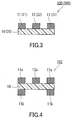
- FIG. 3 is a cross-sectional view of the waterproof sound transmitting member 100, taken along the line X-X.
- the waterproof sound transmitting member 100 includes the waterproof sound transmitting membrane 10 that allows sound to pass therethrough and prevents liquid from passing therethrough, and a first adhesive sheet 11 and a second adhesive sheet 12 that are disposed on a first surface of the waterproof sound transmitting membrane 10.
- the first surface is one principal surface of the waterproof sound transmitting membrane 10 selected from two principal surfaces thereof. No adhesive sheet is disposed on a second surface of the waterproof sound transmitting membrane 10.
- the second surface is the other principal surface of the waterproof sound transmitting membrane 10.
- the first adhesive sheet 11 and the second adhesive sheet 12 are adhesive sheets, both sides of which have adhesive properties. That is, they are double-sided adhesive tapes.
- the waterproof sound transmitting membrane 10 is a membrane member whose principal surface has a circular outline.
- the first adhesive sheet 11 is a closed frame having a disk-shaped window formed in the center of a disk-shaped sheet. More specifically, the first adhesive sheet 11 is a ring-shaped member disposed on the waterproof sound transmitting membrane 10 such that the outer edge of the first adhesive sheet 11 and the outer edge of the waterproof sound transmitting membrane 10 coincide with each other.
- the second adhesive sheet 12 is disposed within the frame formed by the first adhesive sheet 11, that is, in a region surrounded by the inner edge 15 of the first adhesive sheet 11, and is spaced from the first adhesive sheet 11, when viewed in a direction perpendicular to the first surface of the waterproof sound transmitting membrane 10.
- the second adhesive sheet 12 has a circular shape smaller than a circular region surrounded by the inner edge 15, when viewed in the direction perpendicular to the first surface.
- the first surface of the waterproof sound transmitting membrane 10 is divided into a ring-shaped region covered by the first adhesive sheet 11, a ring-shaped region to which the waterproof sound transmitting membrane 10 is exposed between the first adhesive sheet 11 and the second adhesive sheet 12, and a circular region covered by the second adhesive sheet 12, in order from the outer edge side.
- the area of the principal surface of the waterproof sound transmitting membrane 10 is larger than the total of the area of the principal surface of the first adhesive sheet 11 and the area of the principal surface of the second adhesive sheet 12.
- FIG. 2 is a top view showing a waterproof sound transmitting member 200 according to another embodiment of the present invention.
- the waterproof sound transmitting member 200 is the same as the waterproof sound transmitting member 100 shown in FIG. 1 , except for the shape of a waterproof sound transmitting membrane 20, the shape of a first adhesive sheet 21, and the shape of a second adhesive sheet 22, as seen from above in the direction perpendicular to the first principal surface of the waterproof sound transmitting membrane 20.
- FIG. 3 shows the cross-sectional view of the waterproof sound transmitting member 200, taken along the line X-X in FIG. 2 .
- the waterproof sound transmitting membrane 20 is a membrane member whose principal surface has a rectangular outline.
- the first adhesive sheet 21 has a closed frame shape having a rectangular window formed in the center of a rectangular sheet.
- the first adhesive sheet 21 is a rectangular frame-shaped member disposed on the waterproof sound transmitting membrane 20 such that the outer edge of the first adhesive sheet 21 and the outer edge of the waterproof sound transmitting membrane 20 coincide with each other.
- the second adhesive sheet 22 is disposed within the frame formed by the first adhesive sheet 21, that is, in a region surrounded by the inner edge 25 of the first adhesive sheet 21, and is spaced from the first adhesive sheet 21, when viewed in the direction perpendicular to the first surface of the waterproof sound transmitting membrane 20.
- the second adhesive sheet 22 has a rectangular shape smaller than a rectangular region surrounded by the inner edge 25 of the first adhesive sheet 21, when viewed in the direction perpendicular to the first surface.
- the first surface of the waterproof sound transmitting membrane 20 is divided into a rectangular frame-shaped region covered by the first adhesive sheet 21, a rectangular frame-shaped region to which the waterproof sound transmitting membrane 20 is exposed between the first adhesive sheet 21 and the second adhesive sheet 22, and a rectangular region covered by the second adhesive sheet 22, in order from the outer edge side.
- the area of the principal surface of the waterproof sound transmitting membrane 20 is larger than the total of the area of the principal surface of the first adhesive sheet 21 and the area of the principal surface of the second adhesive sheet 22.
- the area of the second adhesive sheet 12 (22) is not more than one half the area of a region surrounded by the inner edge 15 (25) of the frame formed by the first adhesive sheet 11 (21), when viewed in the direction perpendicular to the first surface of the waterproof sound transmitting member 10 (20).
- the area of the second adhesive sheet 12 (22) satisfies the above condition, it is easier to ensure good sound transmission of the waterproof sound transmitting member 100 (200) while preventing sagging of the waterproof sound transmitting membrane 10 (20).
- the lower limit of the area of the second adhesive sheet 12 (22) is not particularly limited, but it is, for example, at least one tenth the area of the region surrounded by the inner edge 15 (25) of the frame formed by the first adhesive sheet 11 (21), when viewed in the direction perpendicular to the first surface of the waterproof sound transmitting member 10 (20).
- FIG. 5 is a top view showing an embodiment of an acoustic component 300 including the waterproof sound transmitting member 100.
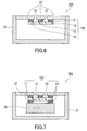
- FIG. 6 is a cross-sectional view of the acoustic component 300, taken along the line X-X in FIG. 5 .
- a housing is formed of a storage case 31 and a perforated plate 32 covering an opening of the storage case 31.
- a transducer for example, a speaker, a microphone, or a buzzer
- the perforated plate 32 has formed therein holes 33 for allowing passage of sound between the interior and exterior of the housing.
- a broken line 34 indicates the position of the outer edge of the first adhesive sheet 11 and that of the waterproof sound transmitting membrane 11
- a broken line 35 indicates the position of the inner edge of the first adhesive sheet 11
- a broken line 36 indicates the position of the outer edge of the second adhesive sheet 12.
- the waterproof sound transmitting member 100 is fixed to the inner surface of the perforated plate 32 by the first adhesive sheet 11 and the second adhesive sheet 12 so as to cover the holes 33.
- the holes 33 are located in a ring-shaped region inside the line 35 of the inner edge of the first adhesive sheet 11 and outside the line 36 of the outer edge of the second adhesive sheet 12.
- the first adhesive sheet 11 fixes the waterproof sound transmitting membrane 10 and the housing together and prevents water from entering the housing together with the waterproof sound transmitting membrane 10.
- the first adhesive sheet 11 serves to provide waterproof function to the acoustic component 300.
- the second adhesive sheet 12 fixes the waterproof sound transmitting membrane 10 and the housing together in the region surrounded by the first adhesive sheet 11.
- the second adhesive sheet 12 serves to prevent sagging of the waterproof sound transmitting membrane 10. Preventing sagging of the waterproof sound transmitting membrane 10 makes it possible to avoid a contact of the waterproof sound transmitting membrane 10 with the surrounding components and sound distortion. Since the second adhesive sheet 12 is spaced from the first adhesive sheet 11, the region to which the waterproof sound transmitting membrane 10 is exposed forms a single continuous region.
- the membrane When the membrane is divided into regions, the sound energy passing through a smaller area region does not sufficiently contribute to increase the total sound energy passing through the membrane. Therefore, a configuration in which the waterproof sound transmitting membrane is exposed to a single continuous region is advantageous in reducing the loss of sound energy.
- the shapes of the waterproof sound transmitting membrane 10, the first adhesive sheet 11, and the second adhesive sheet 12 may be determined as appropriate depending on the position, shape, size, etc. of the holes 33 of the perforated plate 32.
- the shape of the first adhesive sheet 11 may be determined so that the holes 33 to be protected from water can be located inside the inner edge 35 of the first adhesive sheet 11.
- the shape of the first adhesive sheet 11 may be determined so that the outer edge 34 of the first adhesive sheet 11 and the outer edge of the waterproof sound transmitting membrane 10 coincide with each other.
- the second adhesive sheet 12 is disposed inside the inner edge 35 of the first adhesive sheet 11 and is spaced from the first adhesive sheet 11.
- the shape of the second adhesive sheet 12 may be determined so that the second adhesive sheet 12 does not extend into the region in which the holes 33 are formed.
- the center of gravity of the second adhesive sheet 12 (22) coincide with that of the region surrounded by the inner edge 15 (35) of the first adhesive sheet 11 (21), when viewed in the direction perpendicular to the first surface of the waterproof sound transmitting membrane 10 (20), as in the waterproof sound transmitting member 100 (200) shown in FIG. 1 (FIG.2 ). It is more preferable that the center of gravity of the second adhesive sheet 12 (22) also coincide with that of the waterproof sound transmitting membrane 10 (20).
- the adhesive sheets 11 (21) and 12 (22) are disposed on only one of the two principal surfaces (i.e., the first surface) of the waterproof sound transmitting membrane 10 (20), as shown in FIG. 3 .
- the arrangement of adhesive sheets is not limited to this.
- adhesive sheets may be arranged so that a first adhesive sheet 11a and a second adhesive sheet 12a are disposed on the first surface of the waterproof sound transmitting membrane 10 and a third adhesive sheet 11b having a closed frame shape is disposed on the principal surface (second surface) opposite to the first surface. No other adhesive sheet than the third adhesive sheet 11b is disposed on the second surface.
- the third adhesive sheet 11b has the same shape as the first adhesive sheet 11a.
- an acoustic component 301 having a cross-sectional structure shown in FIG. 7 can be obtained.
- the acoustic component 301 includes a transducer 38 inside the housing formed of the storage case 31 and the perforated plate 32.
- the waterproof sound transmitting member 102 is fixed to the perforated plate 32 by the first adhesive sheet 11 and the second adhesive sheet 12 that are disposed on one of the principal surfaces of the waterproof sound transmitting membrane 10, and is fixed to the transducer 38 by the adhesive sheet (third adhesive sheet) disposed on the other principal surface of the waterproof sound transmitting membrane 10.
- the waterproof sound transmitting membrane 10 includes the third adhesive sheet, it is preferable that, as shown in FIG. 4 , the first adhesive sheet 11a and the third adhesive sheet 11b not only have the same shape but also be located at the same position when viewed in the direction perpendicular to the principal surface of the waterproof sound transmitting membrane 10. That is, it is preferable that the outer edge and the inner edge of the frame-shaped first adhesive sheet 11a coincide with those of the frame-shaped third adhesive sheet 11b in the thickness direction of the waterproof sound transmitting membrane 10.
- the thickness of the waterproof sound transmitting membrane 10 can be adjusted as appropriate depending on the waterproofness, strength and sound transmission required, the configuration of the acoustic component 300, etc.
- the thickness of the waterproof sound transmitting membrane 10 is, for example, 5 to 100 ⁇ m.
- the unwrinkled and unsagged waterproof sound transmitting membrane 10 having a flat principal surface is attached to the housing with the first adhesive sheet 11 and the second adhesive sheet 12 interposed therebetween.
- the first adhesive sheet 11 and the second adhesive sheet 12 have the same thickness.
- the thinner first and second adhesive sheets 11 and 12 are preferred in terms of miniaturization of the acoustic component 300.
- the waterproof sound transmitting membrane 10 vibrated by sound waves may come into contact with other components such as the perforated plate 32, or the waterproof sound transmitting membrane 10 may be more susceptible to damage from outside foreign substances passing through the holes 33, depending on the structure of the acoustic component 300.
- the thickness of the first adhesive sheet 11 and the second adhesive sheet 12 may be, for example, 30 ⁇ m to 200 ⁇ m.
- the width of the frame formed by the first adhesive sheet 11, that is, the distance between the outer edge 34 and the inner edge 35 of the first adhesive sheet 11 is suitably 0.5 mm to 5 mm, for example, for ensuring waterproofness, although the suitable width may vary depending on the structure of the acoustic component 300 to which the waterproof sound transmitting member 100 is to be attached.
- the materials that can be used for the waterproof sound transmitting membrane 10 are, for example, polymer films made of polymers, such as polyethylene, polypropylene, polyimide, polyethylene terephthalate, and polytetrafluoroethylene (PTFE), and porous membranes made from the polymer films, water-repellent nonwoven fabrics, and nanofiber membranes.
- the waterproof sound transmitting membrane 10 is a single layer sheet, but it may be a layered product of sheets.
- the waterproof sound transmitting membrane 10 includes a porous PTFE membrane because of its high water repellency and high sound transmission.
- double-sided adhesive tapes in particular, sheets including a base material layer and an acrylic or silicone adhesive layers disposed on both sides of the base material layer are suitably used.
- the present invention is particularly effective when it is applied to a waterproof sound transmitting member including a large-diameter waterproof sound transmitting membrane, because such a large-diameter waterproof sound transmitting membrane is likely to sag under its own weight and thus to come into contact with the surrounding components, causing sound distortion. Therefore, it is preferable to apply the present invention to a waterproof sound transmitting member including a waterproof sound transmitting membrane with a maximum diameter of 3 mm or more, in particular, 5 mm or more, for example, 7 mm to 20 mm. As used herein, the maximum diameter refers to the longest length of a line passing through the center of gravity of the principal surface of the waterproof sound transmitting membrane.
- the waterproof sound transmitting member of the present invention can be used as a member attachable to acoustic components in various acoustic devices.
- the waterproof sound transmitting member of the present invention has a structure suitable for preventing sagging of a waterproof sound transmitting membrane, while ensuring sound transmission.
- the waterproof sound transmitting member of the present invention is also suitable for reducing a space in a housing required for attachment of a waterproof sound transmitting member.
- the waterproof sound transmitting member of the present invention can be suitably used particularly for acoustic devices in small electronic devices, such as microphones in cellular phones.
Landscapes
- Physics & Mathematics (AREA)
- Engineering & Computer Science (AREA)
- Acoustics & Sound (AREA)
- Signal Processing (AREA)
- Details Of Audible-Bandwidth Transducers (AREA)
- Telephone Set Structure (AREA)
Description
- The present invention relates to a waterproof sound transmitting member suitable for providing waterproof function to electronic devices equipped with acoustic components such as microphones and speakers, and in particular, to a waterproof sound transmitting member including a waterproof sound transmitting membrane.
- Portable electronic devices, such as cellular phones, cordless phones, smartphones, notebook computers, tablet computers, electronic notebooks, digital cameras, and portable game machines, are required to be waterproof because the devices are often used outdoors. In these electronic devices, acoustic components, specifically, transducers serving as sound transmitters or sound receivers, such as speakers, microphones, and buzzers, need to transmit sound to the outside of the devices and to receive sound from the outside thereof. Therefore, various studies have been conducted to achieve both sound transmission and waterproofness.
- One of the known ways to provide both waterproofness and sound transmission (waterproof sound transmission function) to an electronic device is to attach a waterproof sound transmitting membrane to a housing of the electronic device to cover an opening formed in the housing. Nonwoven fabrics or porous polymer membranes and films are used as waterproof sound transmitting membranes. Waterproof sound transmitting members each including a waterproof sound transmitting membrane and a fixing member for fixing the waterproof sound transmitting membrane are disclosed in
JP 2001-148897 A JP 2004-083811 A JP 2012-165353 A JP 2012-165353 A U.S. Patent 5,828,012 discloses a sound-transmissive cover assembly comprising a protective membrane layer which is selectively bonded to a layer of porous support material. - As the fixing member for fixing the waterproof sound transmitting membrane, an adhesive sheet or an adhesive disposed or applied between the edge of the opening to be protected from water and the outer edge of the waterproof sound transmitting membrane is known. However, when an adhesive sheet or an adhesive is used as the fixing member, the waterproof sound transmitting membrane is usually attached to the inner surface of the housing. Therefore, the waterproof sound transmitting membrane sagging under its own weight may come into contact with the transducer and other components around the transducer, resulting in distortion of sound. Since electronic devices have recently become smaller and lighter, the risk that sagging of a waterproof sound transmitting membrane may cause deterioration in sound quality has increased. In particular, a waterproof sound transmitting membrane having a large diameter is more likely to come into contact with the surrounding components.
- In view of the above, it is an object of the present invention to provide a waterproof sound transmitting member having a structure suitable for preventing deterioration in sound quality due to sagging of the waterproof sound transmitting membrane.
- The present invention provides a waterproof sound transmitting member which is disclosed in appended claim 1 and includes: a waterproof sound transmitting membrane that allows sound to pass therethrough and prevents water from passing therethrough, the waterproof sound transmitting membrane having a first surface and a second surface opposite to the first surface; and a first adhesive sheet and a second adhesive sheet that are disposed on the first surface. When viewed in a direction perpendicular to the first surface, the first adhesive sheet has a closed frame shape, and the second adhesive sheet is disposed within the frame formed by the first adhesive sheet and is spaced from the first adhesive sheet. The waterproof sound transmitting membrane has a maximum diameter of 7 mm to 20 mm. When viewed in a direction perpendicular to the first surface, an area of the second adhesive sheet is at least one tenth and not more than one half an area of a region surrounded by an inner edge of the frame formed by the first adhesive sheet.
- In the waterproof sound transmitting member of the present invention, the waterproof sound transmitting membrane and the first adhesive sheet block the passage of water through the opening to be protected from water. The second adhesive sheet also is disposed on the waterproof sound transmitting membrane so that the first and second adhesive sheets are placed on the same surface. The second adhesive sheet allows to ensure good sound transmission while preventing sagging of the waterproof sound transmitting membrane.
-
FIG. 1 is a top view showing an embodiment of a waterproof sound transmitting member of the present invention. -
FIG. 2 is a top view showing another embodiment of the waterproof sound transmitting member of the present invention. -
FIG. 3 is an example of a cross-sectional view of the waterproof sound transmitting member, taken along the line X-X inFIG. 1 or FIG. 2 . -
FIG. 4 is another example of the cross-sectional view of the waterproof sound transmitting member. -
FIG. 5 is a top view showing an embodiment of an acoustic component including the waterproof sound transmitting member. -
FIG. 6 is a cross-sectional view of the acoustic component, taken along the line X-X inFIG. 5 . -
FIG. 7 is a cross-sectional view of the acoustic component including the waterproof sound transmitting member inFIG. 4 . - Hereinafter, embodiments of the present invention will be described with reference to the drawings, but the present invention is not limited to the following description. As is apparent from the following description and drawings, a "principal surface" in this specification refers to the surface extending in a direction perpendicular to the thickness direction of a membrane or a sheet.
-
FIG. 1 is a view of a waterproofsound transmitting member 100 according to an embodiment of the present invention, as seen from above in a direction perpendicular to the principal surface of a waterproofsound transmitting membrane 10.FIG. 3 is a cross-sectional view of the waterproofsound transmitting member 100, taken along the line X-X. The waterproofsound transmitting member 100 includes the waterproofsound transmitting membrane 10 that allows sound to pass therethrough and prevents liquid from passing therethrough, and a firstadhesive sheet 11 and a secondadhesive sheet 12 that are disposed on a first surface of the waterproofsound transmitting membrane 10. The first surface is one principal surface of the waterproofsound transmitting membrane 10 selected from two principal surfaces thereof. No adhesive sheet is disposed on a second surface of the waterproofsound transmitting membrane 10. The second surface is the other principal surface of the waterproofsound transmitting membrane 10. For example, the firstadhesive sheet 11 and the secondadhesive sheet 12 are adhesive sheets, both sides of which have adhesive properties. That is, they are double-sided adhesive tapes. The waterproofsound transmitting membrane 10 is a membrane member whose principal surface has a circular outline. The firstadhesive sheet 11 is a closed frame having a disk-shaped window formed in the center of a disk-shaped sheet. More specifically, the firstadhesive sheet 11 is a ring-shaped member disposed on the waterproofsound transmitting membrane 10 such that the outer edge of the firstadhesive sheet 11 and the outer edge of the waterproofsound transmitting membrane 10 coincide with each other. The secondadhesive sheet 12 is disposed within the frame formed by the firstadhesive sheet 11, that is, in a region surrounded by theinner edge 15 of the firstadhesive sheet 11, and is spaced from the firstadhesive sheet 11, when viewed in a direction perpendicular to the first surface of the waterproofsound transmitting membrane 10. The secondadhesive sheet 12 has a circular shape smaller than a circular region surrounded by theinner edge 15, when viewed in the direction perpendicular to the first surface. Thus, the first surface of the waterproofsound transmitting membrane 10 is divided into a ring-shaped region covered by the firstadhesive sheet 11, a ring-shaped region to which the waterproofsound transmitting membrane 10 is exposed between the firstadhesive sheet 11 and the secondadhesive sheet 12, and a circular region covered by the secondadhesive sheet 12, in order from the outer edge side. The area of the principal surface of the waterproofsound transmitting membrane 10 is larger than the total of the area of the principal surface of the firstadhesive sheet 11 and the area of the principal surface of the secondadhesive sheet 12. -
FIG. 2 is a top view showing a waterproofsound transmitting member 200 according to another embodiment of the present invention. The waterproofsound transmitting member 200 is the same as the waterproofsound transmitting member 100 shown inFIG. 1 , except for the shape of a waterproofsound transmitting membrane 20, the shape of a firstadhesive sheet 21, and the shape of a secondadhesive sheet 22, as seen from above in the direction perpendicular to the first principal surface of the waterproofsound transmitting membrane 20.FIG. 3 shows the cross-sectional view of the waterproofsound transmitting member 200, taken along the line X-X inFIG. 2 . The waterproofsound transmitting membrane 20 is a membrane member whose principal surface has a rectangular outline. The firstadhesive sheet 21 has a closed frame shape having a rectangular window formed in the center of a rectangular sheet. More specifically, the firstadhesive sheet 21 is a rectangular frame-shaped member disposed on the waterproofsound transmitting membrane 20 such that the outer edge of the firstadhesive sheet 21 and the outer edge of the waterproofsound transmitting membrane 20 coincide with each other. The secondadhesive sheet 22 is disposed within the frame formed by the firstadhesive sheet 21, that is, in a region surrounded by theinner edge 25 of the firstadhesive sheet 21, and is spaced from the firstadhesive sheet 21, when viewed in the direction perpendicular to the first surface of the waterproofsound transmitting membrane 20. The secondadhesive sheet 22 has a rectangular shape smaller than a rectangular region surrounded by theinner edge 25 of the firstadhesive sheet 21, when viewed in the direction perpendicular to the first surface. Thus, the first surface of the waterproofsound transmitting membrane 20 is divided into a rectangular frame-shaped region covered by the firstadhesive sheet 21, a rectangular frame-shaped region to which the waterproofsound transmitting membrane 20 is exposed between the firstadhesive sheet 21 and the secondadhesive sheet 22, and a rectangular region covered by the secondadhesive sheet 22, in order from the outer edge side. The area of the principal surface of the waterproofsound transmitting membrane 20 is larger than the total of the area of the principal surface of the firstadhesive sheet 21 and the area of the principal surface of the secondadhesive sheet 22. - Preferably, the area of the second adhesive sheet 12 (22) is not more than one half the area of a region surrounded by the inner edge 15 (25) of the frame formed by the first adhesive sheet 11 (21), when viewed in the direction perpendicular to the first surface of the waterproof sound transmitting member 10 (20). When the area of the second adhesive sheet 12 (22) satisfies the above condition, it is easier to ensure good sound transmission of the waterproof sound transmitting member 100 (200) while preventing sagging of the waterproof sound transmitting membrane 10 (20). The lower limit of the area of the second adhesive sheet 12 (22) is not particularly limited, but it is, for example, at least one tenth the area of the region surrounded by the inner edge 15 (25) of the frame formed by the first adhesive sheet 11 (21), when viewed in the direction perpendicular to the first surface of the waterproof sound transmitting member 10 (20).
-
FIG. 5 is a top view showing an embodiment of anacoustic component 300 including the waterproofsound transmitting member 100.FIG. 6 is a cross-sectional view of theacoustic component 300, taken along the line X-X inFIG. 5 . In theacoustic component 300, a housing is formed of astorage case 31 and aperforated plate 32 covering an opening of thestorage case 31. A transducer (for example, a speaker, a microphone, or a buzzer) not shown is placed in thestorage case 31. Theperforated plate 32 has formed thereinholes 33 for allowing passage of sound between the interior and exterior of the housing. InFIG. 5 , abroken line 34 indicates the position of the outer edge of the firstadhesive sheet 11 and that of the waterproofsound transmitting membrane 11, abroken line 35 indicates the position of the inner edge of the firstadhesive sheet 11, and abroken line 36 indicates the position of the outer edge of the secondadhesive sheet 12. The waterproofsound transmitting member 100 is fixed to the inner surface of theperforated plate 32 by thefirst adhesive sheet 11 and thesecond adhesive sheet 12 so as to cover theholes 33. When viewed in the direction perpendicular to the first surface of the waterproofsound transmitting membrane 10, theholes 33 are located in a ring-shaped region inside theline 35 of the inner edge of thefirst adhesive sheet 11 and outside theline 36 of the outer edge of thesecond adhesive sheet 12. - The
first adhesive sheet 11 fixes the waterproofsound transmitting membrane 10 and the housing together and prevents water from entering the housing together with the waterproofsound transmitting membrane 10. Thus, thefirst adhesive sheet 11 serves to provide waterproof function to theacoustic component 300. Thesecond adhesive sheet 12 fixes the waterproofsound transmitting membrane 10 and the housing together in the region surrounded by thefirst adhesive sheet 11. Thus, thesecond adhesive sheet 12 serves to prevent sagging of the waterproofsound transmitting membrane 10. Preventing sagging of the waterproofsound transmitting membrane 10 makes it possible to avoid a contact of the waterproofsound transmitting membrane 10 with the surrounding components and sound distortion. Since thesecond adhesive sheet 12 is spaced from thefirst adhesive sheet 11, the region to which the waterproofsound transmitting membrane 10 is exposed forms a single continuous region. When the membrane is divided into regions, the sound energy passing through a smaller area region does not sufficiently contribute to increase the total sound energy passing through the membrane. Therefore, a configuration in which the waterproof sound transmitting membrane is exposed to a single continuous region is advantageous in reducing the loss of sound energy. - The shapes of the waterproof
sound transmitting membrane 10, thefirst adhesive sheet 11, and thesecond adhesive sheet 12 may be determined as appropriate depending on the position, shape, size, etc. of theholes 33 of theperforated plate 32. For example, the shape of thefirst adhesive sheet 11 may be determined so that theholes 33 to be protected from water can be located inside theinner edge 35 of thefirst adhesive sheet 11. The shape of thefirst adhesive sheet 11 may be determined so that theouter edge 34 of thefirst adhesive sheet 11 and the outer edge of the waterproofsound transmitting membrane 10 coincide with each other. - The
second adhesive sheet 12 is disposed inside theinner edge 35 of thefirst adhesive sheet 11 and is spaced from thefirst adhesive sheet 11. The shape of thesecond adhesive sheet 12 may be determined so that thesecond adhesive sheet 12 does not extend into the region in which theholes 33 are formed. In order to cause the waterproofsound transmitting membrane 10 to vibrate uniformly and reduce the loss of sound energy, it is preferable that the center of gravity of the second adhesive sheet 12 (22) coincide with that of the region surrounded by the inner edge 15 (35) of the first adhesive sheet 11 (21), when viewed in the direction perpendicular to the first surface of the waterproof sound transmitting membrane 10 (20), as in the waterproof sound transmitting member 100 (200) shown inFIG. 1 (FIG.2 ). It is more preferable that the center of gravity of the second adhesive sheet 12 (22) also coincide with that of the waterproof sound transmitting membrane 10 (20). - In the waterproof sound transmitting member 100 (200) shown in
FIG. 1 (FIG. 2 ), the adhesive sheets 11 (21) and 12 (22) are disposed on only one of the two principal surfaces (i.e., the first surface) of the waterproof sound transmitting membrane 10 (20), as shown inFIG. 3 . However, the arrangement of adhesive sheets is not limited to this. For example, as in a waterproofsound transmitting member 102 shown inFIG. 4 , adhesive sheets may be arranged so that a firstadhesive sheet 11a and a secondadhesive sheet 12a are disposed on the first surface of the waterproofsound transmitting membrane 10 and a thirdadhesive sheet 11b having a closed frame shape is disposed on the principal surface (second surface) opposite to the first surface. No other adhesive sheet than the thirdadhesive sheet 11b is disposed on the second surface. Preferably, the thirdadhesive sheet 11b has the same shape as the firstadhesive sheet 11a. - In the case where the waterproof
sound transmitting member 102 having a cross-sectional structure shown inFIG. 4 is used, for example, anacoustic component 301 having a cross-sectional structure shown inFIG. 7 can be obtained. Theacoustic component 301 includes atransducer 38 inside the housing formed of thestorage case 31 and theperforated plate 32. The waterproofsound transmitting member 102 is fixed to theperforated plate 32 by thefirst adhesive sheet 11 and thesecond adhesive sheet 12 that are disposed on one of the principal surfaces of the waterproofsound transmitting membrane 10, and is fixed to thetransducer 38 by the adhesive sheet (third adhesive sheet) disposed on the other principal surface of the waterproofsound transmitting membrane 10. - Sound passes through the region to which the waterproof
sound transmitting membrane 10 is exposed, that is, the frame-shaped region between the inner edge of thefirst adhesive sheet 11 and the outer edge of thesecond adhesive sheet 12, and thus is transmitted. The larger the exposure area of the waterproofsound transmitting membrane 10, the smaller the loss of sound energy caused by the passage of sound through the waterproofsound transmitting membrane 10. Therefore, in the case where the waterproofsound transmitting membrane 10 includes the third adhesive sheet, it is preferable that, as shown inFIG. 4 , the firstadhesive sheet 11a and the thirdadhesive sheet 11b not only have the same shape but also be located at the same position when viewed in the direction perpendicular to the principal surface of the waterproofsound transmitting membrane 10. That is, it is preferable that the outer edge and the inner edge of the frame-shaped firstadhesive sheet 11a coincide with those of the frame-shaped thirdadhesive sheet 11b in the thickness direction of the waterproofsound transmitting membrane 10. - The thickness of the waterproof
sound transmitting membrane 10 can be adjusted as appropriate depending on the waterproofness, strength and sound transmission required, the configuration of theacoustic component 300, etc. The thickness of the waterproofsound transmitting membrane 10 is, for example, 5 to 100 µm. - Preferably, the unwrinkled and unsagged waterproof
sound transmitting membrane 10 having a flat principal surface is attached to the housing with thefirst adhesive sheet 11 and thesecond adhesive sheet 12 interposed therebetween. In order to facilitate the attachment of the membrane, it is preferable that thefirst adhesive sheet 11 and thesecond adhesive sheet 12 have the same thickness. The thinner first and secondadhesive sheets acoustic component 300. However, if the thickness of thefirst adhesive sheet 11 and thesecond adhesive sheet 12 is too small, the waterproofsound transmitting membrane 10 vibrated by sound waves may come into contact with other components such as theperforated plate 32, or the waterproofsound transmitting membrane 10 may be more susceptible to damage from outside foreign substances passing through theholes 33, depending on the structure of theacoustic component 300. The thickness of thefirst adhesive sheet 11 and thesecond adhesive sheet 12 may be, for example, 30 µm to 200 µm. - The width of the frame formed by the
first adhesive sheet 11, that is, the distance between theouter edge 34 and theinner edge 35 of thefirst adhesive sheet 11 is suitably 0.5 mm to 5 mm, for example, for ensuring waterproofness, although the suitable width may vary depending on the structure of theacoustic component 300 to which the waterproofsound transmitting member 100 is to be attached. - The materials that can be used for the waterproof
sound transmitting membrane 10 are, for example, polymer films made of polymers, such as polyethylene, polypropylene, polyimide, polyethylene terephthalate, and polytetrafluoroethylene (PTFE), and porous membranes made from the polymer films, water-repellent nonwoven fabrics, and nanofiber membranes. The waterproofsound transmitting membrane 10 is a single layer sheet, but it may be a layered product of sheets. Preferably, the waterproofsound transmitting membrane 10 includes a porous PTFE membrane because of its high water repellency and high sound transmission. - As the adhesive sheets such as the
first adhesive sheet 11 and thesecond adhesive sheet 12, double-sided adhesive tapes, in particular, sheets including a base material layer and an acrylic or silicone adhesive layers disposed on both sides of the base material layer are suitably used. - The present invention is particularly effective when it is applied to a waterproof sound transmitting member including a large-diameter waterproof sound transmitting membrane, because such a large-diameter waterproof sound transmitting membrane is likely to sag under its own weight and thus to come into contact with the surrounding components, causing sound distortion. Therefore, it is preferable to apply the present invention to a waterproof sound transmitting member including a waterproof sound transmitting membrane with a maximum diameter of 3 mm or more, in particular, 5 mm or more, for example, 7 mm to 20 mm. As used herein, the maximum diameter refers to the longest length of a line passing through the center of gravity of the principal surface of the waterproof sound transmitting membrane.
- The waterproof sound transmitting member of the present invention can be used as a member attachable to acoustic components in various acoustic devices. The waterproof sound transmitting member of the present invention has a structure suitable for preventing sagging of a waterproof sound transmitting membrane, while ensuring sound transmission. The waterproof sound transmitting member of the present invention is also suitable for reducing a space in a housing required for attachment of a waterproof sound transmitting member. The waterproof sound transmitting member of the present invention can be suitably used particularly for acoustic devices in small electronic devices, such as microphones in cellular phones.
Claims (9)
- A waterproof sound transmitting member (100) comprising:a waterproof sound transmitting membrane (10) that allows sound to pass therethrough and prevents water from passing therethrough, the waterproof sound transmitting membrane having a first surface and a second surface opposite to the first surface,a first adhesive sheet (11) disposed on the first surface,wherein when viewed in a direction perpendicular to the first surface, the first adhesive sheet has a closed frame shape,a second adhesive sheet (12) disposed on the first surface, the second adhesive sheet being disposed within the frame formed by the first adhesive sheet (11) and being spaced from the first adhesive sheet,the waterproof sound transmitting member (100) being characterized in that the waterproof sound transmitting membrane (10) has a maximum diameter of 7 mm to 20 mm, and in that when viewed in the direction perpendicular to the first surface, an area of the second adhesive sheet (12) is at least one tenth and not more than one half an area of a region surrounded by an inner edge of the frame formed by the first adhesive sheet (11).
- The waterproof sound transmitting member according to claim 1, wherein no adhesive sheet is disposed on the second surface.
- The waterproof sound transmitting member according to claim 1, further comprising a third adhesive sheet disposed on the second surface,
wherein
no other adhesive sheet than the third adhesive sheet is disposed on the second surface, and
the third adhesive sheet has the same closed frame shape as the first adhesive sheet (11). - The waterproof sound transmitting member according to any one of claims 1 to 3, wherein a material of the waterproof sound transmitting membrane (10) is selected from polymer films made of polymers and porous membranes made from the polymer films.
- The waterproof sound transmitting member according to any one of claims 1 to 3, wherein the waterproof sound transmitting membrane (10) comprises a porous polytetrafluoroethylene membrane.
- The waterproof sound transmitting member according to any one of claims 1 to 5, wherein when viewed in the direction perpendicular to the first surface, the center of gravity of the second adhesive sheet (12) coincides with the center of gravity of the region surrounded by an inner edge of the first adhesive sheet (11).
- The waterproof sound transmitting member according to any one of claims 1 to 6, wherein the first adhesive sheet (11) and the second adhesive sheet (12) have the same thickness.
- The waterproof sound transmitting member according to any one of claims 1 to 7, wherein
a region to which the waterproof sound transmitting membrane (10) is exposed is a frame-shaped region between an inner edge of the first adhesive sheet (11) and an outer edge of the second adhesive sheet (12). - The waterproof sound transmitting member according to any one of claims 1 to 8, wherein
the first adhesive sheet (11) is configured to fix the waterproof sound transmitting membrane (10) and a housing (31, 32) together, and
the second adhesive sheet (12) is configured to fix the waterproof sound transmitting membrane and the housing together in the region surrounded by the first adhesive sheet (11).
Applications Claiming Priority (1)
| Application Number | Priority Date | Filing Date | Title |
|---|---|---|---|
| JP2013047799A JP2014175907A (en) | 2013-03-11 | 2013-03-11 | Waterproof sound-transmitting member |
Publications (2)
| Publication Number | Publication Date |
|---|---|
| EP2779693A1 EP2779693A1 (en) | 2014-09-17 |
| EP2779693B1 true EP2779693B1 (en) | 2016-08-31 |
Family
ID=50241194
Family Applications (1)
| Application Number | Title | Priority Date | Filing Date |
|---|---|---|---|
| EP14158832.7A Not-in-force EP2779693B1 (en) | 2013-03-11 | 2014-03-11 | Waterproof sound transmitting member |
Country Status (6)
| Country | Link |
|---|---|
| US (1) | US9271070B2 (en) |
| EP (1) | EP2779693B1 (en) |
| JP (1) | JP2014175907A (en) |
| KR (1) | KR20140111595A (en) |
| CN (1) | CN104053078A (en) |
| TW (1) | TW201503705A (en) |
Families Citing this family (15)
| Publication number | Priority date | Publication date | Assignee | Title |
|---|---|---|---|---|
| CN105594225B (en) | 2013-09-30 | 2019-01-04 | 苹果公司 | Water-proof loudspeaker module |
| US9226076B2 (en) | 2014-04-30 | 2015-12-29 | Apple Inc. | Evacuation of liquid from acoustic space |
| JP6472182B2 (en) * | 2014-07-15 | 2019-02-20 | 日東電工株式会社 | Waterproof member and electronic device provided with the waterproof member |
| US9363589B2 (en) * | 2014-07-31 | 2016-06-07 | Apple Inc. | Liquid resistant acoustic device |
| US9681210B1 (en) | 2014-09-02 | 2017-06-13 | Apple Inc. | Liquid-tolerant acoustic device configurations |
| CN204761633U (en) * | 2015-06-10 | 2015-11-11 | 瑞声光电科技(常州)有限公司 | Sounding device |
| US9811121B2 (en) | 2015-06-23 | 2017-11-07 | Apple Inc. | Liquid-resistant acoustic device gasket and membrane assemblies |
| JP2017152945A (en) * | 2016-02-25 | 2017-08-31 | 京セラ株式会社 | Electronic device |
| KR101886166B1 (en) | 2016-07-07 | 2018-09-10 | 주식회사 아모그린텍 | Waterproof sound-transmitting sheet |
| US10209123B2 (en) | 2016-08-24 | 2019-02-19 | Apple Inc. | Liquid detection for an acoustic module |
| US20190174233A1 (en) * | 2017-04-21 | 2019-06-06 | Temco Japan Co., Ltd. | Bone conduction speaker unit |
| CN107318059A (en) * | 2017-08-02 | 2017-11-03 | 苏州孝义家精密金属有限公司 | A kind of ultra-thin water-proof sound-transmitting is combined module |
| JP7019828B2 (en) | 2018-09-21 | 2022-02-15 | 三菱電機株式会社 | Ventilation mechanism of electronic device housing |
| US10609461B1 (en) * | 2018-10-23 | 2020-03-31 | Getac Technology Corporation | Waterproof speaker device |
| CN110856082B (en) * | 2019-10-10 | 2021-06-15 | 瑞声科技(新加坡)有限公司 | Sound production device |
Family Cites Families (14)
| Publication number | Priority date | Publication date | Assignee | Title |
|---|---|---|---|---|
| US5828012A (en) * | 1996-05-31 | 1998-10-27 | W. L. Gore & Associates, Inc. | Protective cover assembly having enhanced acoustical characteristics |
| US6512834B1 (en) | 1999-07-07 | 2003-01-28 | Gore Enterprise Holdings, Inc. | Acoustic protective cover assembly |
| JP3941031B2 (en) | 1999-11-18 | 2007-07-04 | 五郎 山内 | Waterproof electroacoustic transducer |
| JP3773760B2 (en) * | 2000-06-23 | 2006-05-10 | 三菱電機株式会社 | Speaker device and portable device |
| JP2004083811A (en) | 2002-08-28 | 2004-03-18 | Nitto Denko Corp | Waterproof sound-permeable membrane |
| US6932187B2 (en) * | 2003-10-14 | 2005-08-23 | Gore Enterprise Holdings, Inc. | Protective acoustic cover assembly |
| JP4271668B2 (en) * | 2005-03-18 | 2009-06-03 | 株式会社カシオ日立モバイルコミュニケーションズ | Electroacoustic transducer mounting structure |
| KR101035308B1 (en) * | 2006-10-03 | 2011-05-19 | 후지쯔 가부시끼가이샤 | Mobile device, acoustic component placement method and acoustic component assembly |
| JP5088779B2 (en) * | 2007-08-07 | 2012-12-05 | 日本ゴア株式会社 | Electroacoustic transducer, electronic device, waterproof cover, and ventilation test method for electroacoustic transducer |
| JP2010000464A (en) * | 2008-06-20 | 2010-01-07 | Japan Gore Tex Inc | Vent filter and method for manufacturing thereof |
| JP2012114747A (en) * | 2010-11-25 | 2012-06-14 | Kyocera Corp | Covering unit for opening and electronic apparatus including the covering unit |
| JP2012165353A (en) * | 2011-01-21 | 2012-08-30 | Panasonic Corp | Waterproof structure of electronic apparatus |
| CN103404166B (en) * | 2011-03-03 | 2017-05-31 | 日东电工株式会社 | Waterproof sound passing membrane and electric product |
| JP6075163B2 (en) * | 2013-03-29 | 2017-02-08 | 富士通株式会社 | Portable electronic device and waterproofing method for portable electronic device |
-
2013
- 2013-03-11 JP JP2013047799A patent/JP2014175907A/en active Pending
-
2014
- 2014-02-21 TW TW103105810A patent/TW201503705A/en unknown
- 2014-02-25 US US14/189,667 patent/US9271070B2/en active Active
- 2014-02-28 KR KR1020140024536A patent/KR20140111595A/en not_active Withdrawn
- 2014-03-10 CN CN201410085707.7A patent/CN104053078A/en active Pending
- 2014-03-11 EP EP14158832.7A patent/EP2779693B1/en not_active Not-in-force
Non-Patent Citations (1)
| Title |
|---|
| None * |
Also Published As
| Publication number | Publication date |
|---|---|
| TW201503705A (en) | 2015-01-16 |
| EP2779693A1 (en) | 2014-09-17 |
| JP2014175907A (en) | 2014-09-22 |
| KR20140111595A (en) | 2014-09-19 |
| US9271070B2 (en) | 2016-02-23 |
| CN104053078A (en) | 2014-09-17 |
| US20140254849A1 (en) | 2014-09-11 |
Similar Documents
| Publication | Publication Date | Title |
|---|---|---|
| US9271070B2 (en) | Waterproof sound transmitting member | |
| JP6193621B2 (en) | Protective member for acoustic parts and waterproof case | |
| CN102440000B (en) | Splash proof acoustically resistive cover assembly | |
| JP6472182B2 (en) | Waterproof member and electronic device provided with the waterproof member | |
| CN103597849B (en) | Waterproof and sound-passing components | |
| CN102318367A (en) | Sound-transmitting membrane for microphone, sound-transmitting membrane part for microphone comprising same, microphone and electronic device comprising microphone | |
| US9510097B1 (en) | Electronic device and waterproof sheet thereof | |
| KR20100041839A (en) | Water-proof sound-transmitting membrane, method for production of water-proof sound-transmitting membrane, and electrical appliance using the membrane | |
| JP5155927B2 (en) | Waterproof sound-permeable membrane, waterproof sound-permeable member and electrical product using the same | |
| JP2002502561A (en) | Protective cover assembly with sound transfer characteristics | |
| US10945061B2 (en) | Acoustic protective cover including a curable support layer | |
| JP6758796B2 (en) | Waterproof sound absorbing member | |
| US20260107089A1 (en) | Acoustic devices | |
| US20150104595A1 (en) | Perforated protective film for electronic devices | |
| KR102331665B1 (en) | Waterproof sound transmitting member | |
| CN121605651A (en) | Waterproof assembly of acoustic equipment sound through hole |
Legal Events
| Date | Code | Title | Description |
|---|---|---|---|
| 17P | Request for examination filed |
Effective date: 20140311 |
|
| AK | Designated contracting states |
Kind code of ref document: A1 Designated state(s): AL AT BE BG CH CY CZ DE DK EE ES FI FR GB GR HR HU IE IS IT LI LT LU LV MC MK MT NL NO PL PT RO RS SE SI SK SM TR |
|
| AX | Request for extension of the european patent |
Extension state: BA ME |
|
| PUAI | Public reference made under article 153(3) epc to a published international application that has entered the european phase |
Free format text: ORIGINAL CODE: 0009012 |
|
| R17P | Request for examination filed (corrected) |
Effective date: 20150306 |
|
| RBV | Designated contracting states (corrected) |
Designated state(s): AL AT BE BG CH CY CZ DE DK EE ES FI FR GB GR HR HU IE IS IT LI LT LU LV MC MK MT NL NO PL PT RO RS SE SI SK SM TR |
|
| 17Q | First examination report despatched |
Effective date: 20150728 |
|
| GRAP | Despatch of communication of intention to grant a patent |
Free format text: ORIGINAL CODE: EPIDOSNIGR1 |
|
| RIC1 | Information provided on ipc code assigned before grant |
Ipc: H04R 7/10 20060101ALN20160210BHEP Ipc: H04M 1/18 20060101ALN20160210BHEP Ipc: H04M 1/03 20060101ALN20160210BHEP Ipc: H04R 1/02 20060101ALI20160210BHEP Ipc: H04R 1/08 20060101ALI20160210BHEP Ipc: H04R 1/44 20060101AFI20160210BHEP |
|
| INTG | Intention to grant announced |
Effective date: 20160226 |
|
| GRAJ | Information related to disapproval of communication of intention to grant by the applicant or resumption of examination proceedings by the epo deleted |
Free format text: ORIGINAL CODE: EPIDOSDIGR1 |
|
| GRAR | Information related to intention to grant a patent recorded |
Free format text: ORIGINAL CODE: EPIDOSNIGR71 |
|
| GRAS | Grant fee paid |
Free format text: ORIGINAL CODE: EPIDOSNIGR3 |
|
| GRAA | (expected) grant |
Free format text: ORIGINAL CODE: 0009210 |
|
| INTC | Intention to grant announced (deleted) | ||
| RIC1 | Information provided on ipc code assigned before grant |
Ipc: H04R 1/44 20060101AFI20160707BHEP Ipc: H04R 1/08 20060101ALI20160707BHEP Ipc: H04R 1/02 20060101ALI20160707BHEP Ipc: H04M 1/18 20060101ALN20160707BHEP Ipc: H04R 7/10 20060101ALN20160707BHEP Ipc: H04M 1/03 20060101ALN20160707BHEP |
|
| INTG | Intention to grant announced |
Effective date: 20160714 |
|
| AK | Designated contracting states |
Kind code of ref document: B1 Designated state(s): AL AT BE BG CH CY CZ DE DK EE ES FI FR GB GR HR HU IE IS IT LI LT LU LV MC MK MT NL NO PL PT RO RS SE SI SK SM TR |
|
| REG | Reference to a national code |
Ref country code: CH Ref legal event code: EP Ref country code: GB Ref legal event code: FG4D |
|
| REG | Reference to a national code |
Ref country code: IE Ref legal event code: FG4D |
|
| REG | Reference to a national code |
Ref country code: DE Ref legal event code: R096 Ref document number: 602014003337 Country of ref document: DE |
|
| REG | Reference to a national code |
Ref country code: AT Ref legal event code: REF Ref document number: 825889 Country of ref document: AT Kind code of ref document: T Effective date: 20161015 |
|
| REG | Reference to a national code |
Ref country code: LT Ref legal event code: MG4D |
|
| REG | Reference to a national code |
Ref country code: NL Ref legal event code: MP Effective date: 20160831 |
|
| REG | Reference to a national code |
Ref country code: AT Ref legal event code: MK05 Ref document number: 825889 Country of ref document: AT Kind code of ref document: T Effective date: 20160831 |
|
| PG25 | Lapsed in a contracting state [announced via postgrant information from national office to epo] |
Ref country code: RS Free format text: LAPSE BECAUSE OF FAILURE TO SUBMIT A TRANSLATION OF THE DESCRIPTION OR TO PAY THE FEE WITHIN THE PRESCRIBED TIME-LIMIT Effective date: 20160831 Ref country code: NO Free format text: LAPSE BECAUSE OF FAILURE TO SUBMIT A TRANSLATION OF THE DESCRIPTION OR TO PAY THE FEE WITHIN THE PRESCRIBED TIME-LIMIT Effective date: 20161130 Ref country code: FI Free format text: LAPSE BECAUSE OF FAILURE TO SUBMIT A TRANSLATION OF THE DESCRIPTION OR TO PAY THE FEE WITHIN THE PRESCRIBED TIME-LIMIT Effective date: 20160831 Ref country code: HR Free format text: LAPSE BECAUSE OF FAILURE TO SUBMIT A TRANSLATION OF THE DESCRIPTION OR TO PAY THE FEE WITHIN THE PRESCRIBED TIME-LIMIT Effective date: 20160831 Ref country code: LT Free format text: LAPSE BECAUSE OF FAILURE TO SUBMIT A TRANSLATION OF THE DESCRIPTION OR TO PAY THE FEE WITHIN THE PRESCRIBED TIME-LIMIT Effective date: 20160831 |
|
| PG25 | Lapsed in a contracting state [announced via postgrant information from national office to epo] |
Ref country code: NL Free format text: LAPSE BECAUSE OF FAILURE TO SUBMIT A TRANSLATION OF THE DESCRIPTION OR TO PAY THE FEE WITHIN THE PRESCRIBED TIME-LIMIT Effective date: 20160831 Ref country code: ES Free format text: LAPSE BECAUSE OF FAILURE TO SUBMIT A TRANSLATION OF THE DESCRIPTION OR TO PAY THE FEE WITHIN THE PRESCRIBED TIME-LIMIT Effective date: 20160831 Ref country code: LV Free format text: LAPSE BECAUSE OF FAILURE TO SUBMIT A TRANSLATION OF THE DESCRIPTION OR TO PAY THE FEE WITHIN THE PRESCRIBED TIME-LIMIT Effective date: 20160831 Ref country code: AT Free format text: LAPSE BECAUSE OF FAILURE TO SUBMIT A TRANSLATION OF THE DESCRIPTION OR TO PAY THE FEE WITHIN THE PRESCRIBED TIME-LIMIT Effective date: 20160831 Ref country code: SE Free format text: LAPSE BECAUSE OF FAILURE TO SUBMIT A TRANSLATION OF THE DESCRIPTION OR TO PAY THE FEE WITHIN THE PRESCRIBED TIME-LIMIT Effective date: 20160831 Ref country code: GR Free format text: LAPSE BECAUSE OF FAILURE TO SUBMIT A TRANSLATION OF THE DESCRIPTION OR TO PAY THE FEE WITHIN THE PRESCRIBED TIME-LIMIT Effective date: 20161201 |
|
| PG25 | Lapsed in a contracting state [announced via postgrant information from national office to epo] |
Ref country code: RO Free format text: LAPSE BECAUSE OF FAILURE TO SUBMIT A TRANSLATION OF THE DESCRIPTION OR TO PAY THE FEE WITHIN THE PRESCRIBED TIME-LIMIT Effective date: 20160831 Ref country code: EE Free format text: LAPSE BECAUSE OF FAILURE TO SUBMIT A TRANSLATION OF THE DESCRIPTION OR TO PAY THE FEE WITHIN THE PRESCRIBED TIME-LIMIT Effective date: 20160831 |
|
| PG25 | Lapsed in a contracting state [announced via postgrant information from national office to epo] |
Ref country code: SK Free format text: LAPSE BECAUSE OF FAILURE TO SUBMIT A TRANSLATION OF THE DESCRIPTION OR TO PAY THE FEE WITHIN THE PRESCRIBED TIME-LIMIT Effective date: 20160831 Ref country code: CZ Free format text: LAPSE BECAUSE OF FAILURE TO SUBMIT A TRANSLATION OF THE DESCRIPTION OR TO PAY THE FEE WITHIN THE PRESCRIBED TIME-LIMIT Effective date: 20160831 Ref country code: PT Free format text: LAPSE BECAUSE OF FAILURE TO SUBMIT A TRANSLATION OF THE DESCRIPTION OR TO PAY THE FEE WITHIN THE PRESCRIBED TIME-LIMIT Effective date: 20170102 Ref country code: BE Free format text: LAPSE BECAUSE OF FAILURE TO SUBMIT A TRANSLATION OF THE DESCRIPTION OR TO PAY THE FEE WITHIN THE PRESCRIBED TIME-LIMIT Effective date: 20160831 Ref country code: DK Free format text: LAPSE BECAUSE OF FAILURE TO SUBMIT A TRANSLATION OF THE DESCRIPTION OR TO PAY THE FEE WITHIN THE PRESCRIBED TIME-LIMIT Effective date: 20160831 Ref country code: PL Free format text: LAPSE BECAUSE OF FAILURE TO SUBMIT A TRANSLATION OF THE DESCRIPTION OR TO PAY THE FEE WITHIN THE PRESCRIBED TIME-LIMIT Effective date: 20160831 Ref country code: BG Free format text: LAPSE BECAUSE OF FAILURE TO SUBMIT A TRANSLATION OF THE DESCRIPTION OR TO PAY THE FEE WITHIN THE PRESCRIBED TIME-LIMIT Effective date: 20161130 Ref country code: SM Free format text: LAPSE BECAUSE OF FAILURE TO SUBMIT A TRANSLATION OF THE DESCRIPTION OR TO PAY THE FEE WITHIN THE PRESCRIBED TIME-LIMIT Effective date: 20160831 |
|
| REG | Reference to a national code |
Ref country code: DE Ref legal event code: R097 Ref document number: 602014003337 Country of ref document: DE |
|
| PG25 | Lapsed in a contracting state [announced via postgrant information from national office to epo] |
Ref country code: IT Free format text: LAPSE BECAUSE OF FAILURE TO SUBMIT A TRANSLATION OF THE DESCRIPTION OR TO PAY THE FEE WITHIN THE PRESCRIBED TIME-LIMIT Effective date: 20160831 |
|
| PLBE | No opposition filed within time limit |
Free format text: ORIGINAL CODE: 0009261 |
|
| STAA | Information on the status of an ep patent application or granted ep patent |
Free format text: STATUS: NO OPPOSITION FILED WITHIN TIME LIMIT |
|
| 26N | No opposition filed |
Effective date: 20170601 |
|
| PG25 | Lapsed in a contracting state [announced via postgrant information from national office to epo] |
Ref country code: SI Free format text: LAPSE BECAUSE OF FAILURE TO SUBMIT A TRANSLATION OF THE DESCRIPTION OR TO PAY THE FEE WITHIN THE PRESCRIBED TIME-LIMIT Effective date: 20160831 |
|
| REG | Reference to a national code |
Ref country code: CH Ref legal event code: PL |
|
| PG25 | Lapsed in a contracting state [announced via postgrant information from national office to epo] |
Ref country code: MC Free format text: LAPSE BECAUSE OF FAILURE TO SUBMIT A TRANSLATION OF THE DESCRIPTION OR TO PAY THE FEE WITHIN THE PRESCRIBED TIME-LIMIT Effective date: 20160831 |
|
| REG | Reference to a national code |
Ref country code: IE Ref legal event code: MM4A |
|
| REG | Reference to a national code |
Ref country code: FR Ref legal event code: ST Effective date: 20171130 |
|
| PG25 | Lapsed in a contracting state [announced via postgrant information from national office to epo] |
Ref country code: FR Free format text: LAPSE BECAUSE OF NON-PAYMENT OF DUE FEES Effective date: 20170331 Ref country code: LU Free format text: LAPSE BECAUSE OF NON-PAYMENT OF DUE FEES Effective date: 20170311 |
|
| PG25 | Lapsed in a contracting state [announced via postgrant information from national office to epo] |
Ref country code: CH Free format text: LAPSE BECAUSE OF NON-PAYMENT OF DUE FEES Effective date: 20170331 Ref country code: LI Free format text: LAPSE BECAUSE OF NON-PAYMENT OF DUE FEES Effective date: 20170331 Ref country code: IE Free format text: LAPSE BECAUSE OF NON-PAYMENT OF DUE FEES Effective date: 20170311 |
|
| PGFP | Annual fee paid to national office [announced via postgrant information from national office to epo] |
Ref country code: DE Payment date: 20180227 Year of fee payment: 5 |
|
| PG25 | Lapsed in a contracting state [announced via postgrant information from national office to epo] |
Ref country code: MT Free format text: LAPSE BECAUSE OF NON-PAYMENT OF DUE FEES Effective date: 20170311 |
|
| PG25 | Lapsed in a contracting state [announced via postgrant information from national office to epo] |
Ref country code: AL Free format text: LAPSE BECAUSE OF FAILURE TO SUBMIT A TRANSLATION OF THE DESCRIPTION OR TO PAY THE FEE WITHIN THE PRESCRIBED TIME-LIMIT Effective date: 20160831 |
|
| GBPC | Gb: european patent ceased through non-payment of renewal fee |
Effective date: 20180311 |
|
| PG25 | Lapsed in a contracting state [announced via postgrant information from national office to epo] |
Ref country code: GB Free format text: LAPSE BECAUSE OF NON-PAYMENT OF DUE FEES Effective date: 20180311 |
|
| PG25 | Lapsed in a contracting state [announced via postgrant information from national office to epo] |
Ref country code: HU Free format text: LAPSE BECAUSE OF FAILURE TO SUBMIT A TRANSLATION OF THE DESCRIPTION OR TO PAY THE FEE WITHIN THE PRESCRIBED TIME-LIMIT; INVALID AB INITIO Effective date: 20140311 |
|
| REG | Reference to a national code |
Ref country code: DE Ref legal event code: R119 Ref document number: 602014003337 Country of ref document: DE |
|
| PG25 | Lapsed in a contracting state [announced via postgrant information from national office to epo] |
Ref country code: CY Free format text: LAPSE BECAUSE OF NON-PAYMENT OF DUE FEES Effective date: 20160831 |
|
| PG25 | Lapsed in a contracting state [announced via postgrant information from national office to epo] |
Ref country code: MK Free format text: LAPSE BECAUSE OF FAILURE TO SUBMIT A TRANSLATION OF THE DESCRIPTION OR TO PAY THE FEE WITHIN THE PRESCRIBED TIME-LIMIT Effective date: 20160831 |
|
| PG25 | Lapsed in a contracting state [announced via postgrant information from national office to epo] |
Ref country code: DE Free format text: LAPSE BECAUSE OF NON-PAYMENT OF DUE FEES Effective date: 20191001 |
|
| PG25 | Lapsed in a contracting state [announced via postgrant information from national office to epo] |
Ref country code: TR Free format text: LAPSE BECAUSE OF FAILURE TO SUBMIT A TRANSLATION OF THE DESCRIPTION OR TO PAY THE FEE WITHIN THE PRESCRIBED TIME-LIMIT Effective date: 20160831 |
|
| PG25 | Lapsed in a contracting state [announced via postgrant information from national office to epo] |
Ref country code: IS Free format text: LAPSE BECAUSE OF FAILURE TO SUBMIT A TRANSLATION OF THE DESCRIPTION OR TO PAY THE FEE WITHIN THE PRESCRIBED TIME-LIMIT Effective date: 20161231 |